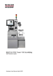
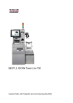
Download BEETLE /iSCAN Scan&Bag
Transcript
BEETLE /iSCAN Scan&Bag Hardware User Manual (May 2006) All product names mentioned in this document are registered trademarks. Copyright © Wincor Nixdorf International GmbH, 2006 All rights including the rights to the translation, reprinting, transmission or copying by any means, in whole or in part, are reserved. Offenders will be liable for damages. All rights including rights resulting from a patent grant or registration of a utility or design are reserved. Contents Introduction .............................................................................................................................................. 1 Safety Instructions ................................................................................................................................... 2 Note on Laser ...................................................................................................................................... 3 BEETLE /iSCAN Scan&Bag - Components ............................................................................................ 4 Pull out the Scanner Carriage ................................................................................................................. 5 Scanner (Scale) ....................................................................................................................................... 6 Scanner Maintenance ...................................................................................................................... 6 Scanner Usage................................................................................................................................. 6 Scanning Items................................................................................................................................. 6 Proper Scanning Technique............................................................................................................. 6 Proper Weighing Technique............................................................................................................. 7 Printer TP07 ............................................................................................................................................ 8 Changing the paper roll...................................................................................................................... 10 Removing the paper roll ................................................................................................................. 10 Setting the paper roll core diameter ............................................................................................... 10 Inserting the paper roll.................................................................................................................... 11 Cash Media Dispenser - Vertical Cash-Out .......................................................................................... 12 Modules and function elements ..................................................................................................... 14 Function elements .......................................................................................................................... 15 Cash-out cassette .......................................................................................................................... 16 Reject / retract cassette.................................................................................................................. 17 Removing the cassette................................................................................................................... 18 Transporting the cassette............................................................................................................... 18 Opening the cassette ..................................................................................................................... 18 Emptying the reject / retract cassette............................................................................................. 19 Filling the cash-out cassette........................................................................................................... 20 Preparing the banknote bundles .................................................................................................... 20 Inserting banknote bundles ............................................................................................................ 21 Possible deformation of banknotes ................................................................................................ 23 Inserting the cassette ..................................................................................................................... 25 Closing the cassette ....................................................................................................................... 25 Inserting the cassette ..................................................................................................................... 26 Cassette initialization...................................................................................................................... 26 Status messages (CMD controller) ................................................................................................ 27 Checking the note paths ................................................................................................................ 29 Coin Change Machine ........................................................................................................................... 34 Controls.............................................................................................................................................. 36 Coin change machine CM-IO-S-6H (L) .......................................................................................... 36 Coin change machine CM-IO-S-6H (R) ......................................................................................... 39 Opening / closing coin change machine CM-IO-S-6H (L).............................................................. 42 Opening / closing coin change machine CM-IO-S-6H (R) ............................................................. 42 Detaching / installing the coin hopper cover ...................................................................................... 43 Detaching / installing the level cover ................................................................................................. 44 Detaching / installing the coinbox ...................................................................................................... 45 Opening / closing the coinbox............................................................................................................ 46 Filling the coin hoppers ...................................................................................................................... 46 Detaching / installing coin hoppers .................................................................................................... 47 Coin chute .......................................................................................................................................... 49 Coin change machine CM-IO-S-6H (L) .......................................................................................... 49 Coin change machine CM-IO-S-6H (R) ......................................................................................... 50 Overview of possible hopper configurations ...................................................................................... 51 Europe (euro) ..................................................................................................................................... 52 Great Britain (GBP) ........................................................................................................................ 53 Description of the coin paths ............................................................................................................. 54 Payment ......................................................................................................................................... 54 Dispensing small change ............................................................................................................... 55 Coin change machine CM-IO-S-6H (R) ......................................................................................... 56 Error messages.................................................................................................................................. 58 Maintenance ...................................................................................................................................... 58 CMD V4-Shutter .................................................................................................................................... 59 Structure............................................................................................................................................. 59 Rear view of frontload version........................................................................................................ 60 Function ............................................................................................................................................. 61 Cash removal ................................................................................................................................. 61 Error code 28.................................................................................................................................. 61 Bank Note Input.................................................................................................................................... 62 Introduction ........................................................................................................................................ 62 Technical Data ................................................................................................................................... 62 Single Banknote Authenticator .............................................................................................................. 63 Controls.............................................................................................................................................. 64 Status LEDs ....................................................................................................................................... 65 Inserting a banknote .......................................................................................................................... 66 Emptying the cassette........................................................................................................................ 67 Description of the banknote path ....................................................................................................... 68 Banknote denominations ................................................................................................................... 68 Removing a banknote jam ................................................................................................................. 70 Banknote jam in the validation unit ................................................................................................ 70 Banknote jam in the transport unit ................................................................................................. 70 Banknote jam at the cassette crossover point ............................................................................... 71 Cleaning and maintenance ................................................................................................................ 72 Validation unit................................................................................................................................. 72 Transport unit ................................................................................................................................. 73 Approved cleaning materials.......................................................................................................... 74 Waiters Lock.......................................................................................................................................... 75 BEETLE /M-II......................................................................................................................................... 76 Front view........................................................................................................................................... 77 Inside view ......................................................................................................................................... 78 Back view ........................................................................................................................................... 78 Appendix................................................................................................................................................ 79 Changing the Safe Code (LG 39E).................................................................................................... 79 Generally ........................................................................................................................................ 80 Programming Manager................................................................................................................... 84 Programming on PC....................................................................................................................... 88 Manual programming ..................................................................................................................... 90 Block Diagram.................................................................................................................................... 92 Environmental Requirements ............................................................................................................ 93 Certifications of the manufacturer ......................................................................................................... 94 Note on Radio Interference Suppression........................................................................................... 94 FCC-Class A Declaration................................................................................................................... 94 Recycling the BEETLE /iSCAN Scan&Bag........................................................................................ 95 BEETLE /iSCAN Scan&Bag Hardware User Manual Introduction The BEETLE /iSCAN is a kiosk terminal which enables the user to carry out a complete purchase transaction without the need of a cashier. At the BEETLE /iSCAN the customer executes the scanning, bagging and paying of the item completely on his own. Each BEETLE /iSCAN kiosk terminal is connected to an attendant station. This is a POS system which controls all connected BEETLE /iSCAN terminals and which is supervised by a human attendant; thus ensuring that the customer will receive human support in case problems should occur at the BEETLE /iSCAN kiosk terminal during transaction. It is possible to connect up to 20 lanes to one attendant station. Prior to the installation of BEETLE /iSCAN, the site has to be prepared carefully and according to specific requirements. These requirements might vary considerably depending on the customers’ requirements as well as on the conditions given at the respective site. In order to avoid deficiencies that may be difficult to detect and/or to correct after the installation the preparatory work is of considerable importance. As BEETLE /iSCAN consists of separate pieces that may be combined in various configurations it is an absolute pre-requisite that you will determine the equipment to be installed at your site. According to this installing information the site preparation can – respectively will have to – proceed. 1 BEETLE /iSCAN Scan&Bag Hardware User Manual Safety Instructions Appliances supplied by Wincor Nixdorf International GmbH comply with the respective safety regulations for data-processing installations and information technology installations, including electrical office equipment for use within an office environment. To disconnect the device from the mains, disconnect the CEE / Nema Type connection or disconnect it by fuse of the building installation. If UPS is installed, you must switch off this too, to separate BEETLE /iSCAN Scan&Bag from power completely! Appliances may only be repaired by authorized technicians. Unauthorized opening of the housing or inexpert repairs can result not only in considerable personal danger, but will also invalidate your warranty and liability protection. Always consult the enclosed documentation before doing any work with this appliance. If this device is brought from a cold environment into a heated place of business, condensation may occur. Before operation, the device must be completely dry. Therefore, an acclimatization period of at least two hours must be adhered to. Exchange damaged cables immediately. Always lay the supply leads and cables in such a way that they cannot be stepped on or tripped over. In order to completely disconnect the device from the power source, turn the device off and use the separator in the fuse box/building installation. Make sure that no objects (such as paper clips) can reach the interior of the device, since electrical shocks or short-circuits could result. To avoid overheating of the power supply unit ensure that the BEETLE /iSCAN receives adequate ventilation. During an electrical storm, data cables should not be plugged in or unplugged. Keep the device away from vibrations, dust, humidity, and heat. The BEETLE /iSCAN is the result of modern technical innovation. Therefore, please also ensure that the BEETLE /iSCAN is operated under modern building and technical conditions in order to ensure flawless and efficient operation. The appliance and other information technology hardware should only be connected to electrical supply networks with a separate protective earth wire (PE). This type of electrical supply network is referred to as a TN-S network. Do not use PEN conductors. Also follow the recommendations set forth in DIN VDE 0100 Part 540, Appendix C2. This will help prevent malfunctions. Always keep the ventilation slots free of obstruction to ensure adequate air circulation and avoid overheating. Transport the appliance only in its original packaging (to protect against knocks and bumps). 2 BEETLE /iSCAN Scan&Bag Hardware User Manual Cleaning Instructions Always turn off the system before cleaning. If liquids were spilled over your System switch off the system and disconnect the power plug. Dry the device with a cloth and leave it switched off for a while. LCD-Displays If the display element is damaged and the liquid crystal solution leaks out onto your hands or clothing, please wash your hands or clothing immediately under running water for at least 15 minutes, using soap or alcohol. If the liquid comes into contact with your eyes, consult a medical doctor immediately. Inside the display, the high voltage needed for backlighting the LCD display is generated by the inverter! High Voltage! Before opening the device, make sure, that the device is disconnected from the main power supply. Opening of the device only by authorized personnel! Note on Laser The PSC 850x Scanner/Scale is not intended for long-term viewing of direct laser light. However, the unit is safe if used as intended. This scanner meets the following laser/LED power requirements. Class IIa Laser—Avoid long-term viewing of direct laser light Class 1 EN60-825 (European Norm) 3 BEETLE /iSCAN Scan&Bag Hardware User Manual BEETLE /iSCAN Scan&Bag - Components 12 10 6 1 4 8 13 13 11 7 9 2 5 9 3 3 1 Screen 2 Scanner/Scale 3 Security Scale 4 Coin input 4 5 6 7 8 Coin Output Note Input Note Output (Shutter) Swipe Card Reader 9 10 11 12 13 Receipt Printer Pole Light Coupon Input Shelf for Baskets EFT BEETLE /iSCAN Scan&Bag Hardware User Manual Pulling out the Scanner Carriage Switch off the system. Unlock the the scanner carriage (arrow). Grab the scanner carriage on both sides and pull it out completely. 1 4 3 2 5 6 7 1 BEETLE /M-II 2 5 Scanner AC Adapter 6 Waiters Lock 3 Shutter 4 Display 7 Key Lock 5 BEETLE /iSCAN Scan&Bag Hardware User Manual Scanner (Scale) Scanner Maintenance Keep scanner windows clean. This will improve productivity and reduce rescans. Replace scanner glass when excessive scratches are evident. Scanner Usage Minimize handling of heavy/bulky products. Leave these items in the cart and use an alternative entry method such as key entry of short PLUs, or handheld scanning. Regularly train cashiers in proper scanning methods and ergonomics principles, such as: Develop a smooth fluid motion during scanning, sharing work equally between hands. Use the entire hand for grasping and lifting items. Since the scanner reads labels on all four sides plus the top and bottom, there is no need to turn a bar code towards either of the scanner windows. Develop efficient scanning motions, not necessarily faster hand movements. Simply slide the item across the scanner’s horizontal window with as little orientation motion as necessary. Leave items in an upright position; do not lift and tilt. Do not favor either the vertical or horizontal window; slide items across the scanner in their natural orientations on the checkstand as much as possible. Scanning Items To scan items, slide or push them through the scan zone. The scanner will work equally well with either a left-to-right or right-to-left motion through the scan zone. There is no need to reorient an item’s bar code since the scanner can “see” the left, right, front and back side, as well as the top and bottom of an item. Proper Scanning Technique The scanner was designed to provide the ultimate in ergonomic enhancements for Point-Of-Sale (POS) scanning. To take advantage of these advancements. Practice the techniques below to improve scanning efficiency: Move the product across the horizontal window. Since the scanner reads labels on all four sides plus the top and bottom, don’t favor either the horizontal or vertical scan windows. Keep items in their natural orientation. Remember to slide or push items rather than picking them up. By avoiding any gripping, twisting and rotation of your hands and wrists, you can prevent repetitive motion injuries. This technique also relieves you from lifting possibly thousands of pounds per day. Develop a smooth fluid motion during scanning, sharing work equally between hands. Use the entire hand for grasping and lifting items. 6 BEETLE /iSCAN Scan&Bag Hardware User Manual Develop efficient scanning motions, not necessarily faster hand movements. Learn typical locations for bar codes on packages; avoid “flipping” or rotating the items during scanning. Proper Weighing Technique The L-shaped All-Weighs™ platter allows you to place items anywhere on its surface, including leaning against its vertical section, to be weighed accurately. The raised “Produce Rail” also provides a convenient way to ensure items do not rest on the counter or other non-weighing surfaces. Once weighed items are in place, enter PLU (price Look-Up) data as described in your POS system instructions. Item weight is displayed on the Remote Display and/or the host display. Remove the item from the weigh platter. It is important that items rest entirely on the platter for their full weight to be accurately recorded. 7 BEETLE /iSCAN Scan&Bag Printer TP07c Turn the key to the right and swing the door open. 8 Hardware User Manual BEETLE /iSCAN Scan&Bag Hardware User Manual The printer is located on the left side (see arrow) Grab the lever (arrow) and pull out the printer completely. 9 BEETLE /iSCAN Scan&Bag Hardware User Manual Changing the paper roll Removing the paper roll Cut off the paper at the paper support. Lift the paper roll with the paper roll holder upwards out of the printer. Use the LINE FEED button to remove the remaining paper. Setting the paper roll core diameter When starting operation of the device or when changing the paper roll diameter check whether the selection switch for the paper near end adjustment is set to the correct position. Core diameter Paper roll diameter 18 mm Pos. A1 25 mm Pos. A2 40 mm Pos. A3 A B A1 A2A3 B3 B2B1 Choose the roll holder which fits to the paper roll core 1 Holder for 18mm core diameter (identifier 1) 2 10 BEETLE /iSCAN Scan&Bag Hardware User Manual Holder for 25mm core diameter (identifier 2) 3 Holder for 40mm core diameter (identifier 3) Inserting the paper roll Push the paper roll holder into the paper roll core. Insert the paper into the printer as shown in the illustration. Mind the direction in which the paper unrolls. Pos. A: For rolls with a diameter of 180 mm Pos.A For correct paper feed or paper transport the front edge of the paper has to be cut with scissors to get a right angled sharp edge. Take the front edge of the paper over the upper axle and feed it into the paper support (see arrow). Keep pushing the paper into the paper support until it is drawn in automatically, cut off and the produced receipt is output via the presenter. If the paper is loaded correctly the following text will be printed on the first receipt: If you can read this print, Autoloading is successful Remove the cut-off receipt. 11 BEETLE /iSCAN Scan&Bag Cash Media Dispenser - Vertical Cash-Out Unlock the door (arrow) and open it. 12 Hardware User Manual BEETLE /iSCAN Scan&Bag Hardware User Manual Enter the pin und turn the wheel to the right (1). Turn the other wheel (2) until you can open the door of the safe. 2 1 Grab the green lever (white arrow) and pull out the Cash Media Dispenser completely. 13 BEETLE /iSCAN Scan&Bag Hardware User Manual Modules and function elements This is not part of BEETLE /iSCAN 1 2 3 4 5 6 7 8 9 10 1 Stacker and output transport facility (SAT) Not in BEETLE /iSCAN Scan&Bag 6 Function key 2 CMD controller 7 Cash-out cassette 1 3 Reject / retract cassette 8 Cash-out cassette 2 4 Status display 9 Cash-out cassette 3 5 Release lever 10 Cash-out cassette 4 (not available) 14 BEETLE /iSCAN Scan&Bag Hardware User Manual Function elements 1 2 1 Status display (two 7-segment displays, first digit on the top) 2 Function key 15 BEETLE /iSCAN Scan&Bag Hardware User Manual Cash-out cassette 15 8 1 9 2 10 3 11 4 12 5 13 6 14 7 16 16 1 Pull-back handle 9 Refill notes 2 Banknote rail 10 Inset for setting the banknote height 3 Slide for low cash sensor (optional) 11 Latching button 4 Pressure carriage 12 Free space for validity identification 5 Tamper indicator blue/green 13 Free space for cassette label 6 Sealing device 14 Cassette handle 7 Locking / unlocking lever (optional lock 15 Dispensing side 8 Cassette lid 16 Side of cassette handle BEETLE /iSCAN Scan&Bag Hardware User Manual Reject / retract cassette 1 2 3 4 5 6 7 1 Cassette lid 5 Tamper indicator blue/green 2 Retract compartment lever 6 Cassette handle 3 Retract compartment 7 Locking / unlocking lever (optional lock) 4 Reject compartment 17 BEETLE /iSCAN Scan&Bag Hardware User Manual Removing the cassette Before cassettes can be removed the BEETLE /iSCAN Scan&Bag Terminal should be shut down. To remove the cassettes from the CMD-V4: Press the green releasing tab on the right side of the cassette (1). The released cassette is automatically pushed out of the dispenser by several centimeters. Raise the cassette handle (2) and pull the cassette out of the CMD-V4 by the handle (2). While pulling the cassette, support it from underneath with your free hand. Transporting the cassette Make sure that the cassette(s) are not damaged or dropped during transport. Opening the cassette The procedure for opening cash-out cassettes and reject/retract cassettes is the same. Remove any seal (1) on a cassette with a sealable lock. Insert the cassette key into the cassette lock, turn the key to the right as far as possible (2) and lift the cassette lid in the direction of the arrow (3). 1 18 BEETLE /iSCAN Scan&Bag Hardware User Manual Emptying the reject / retract cassette The reject / retract cassette is divided into a reject and a retract compartment. Banknotes which are not removed by the customer after the cash dispensing procedure are returned to the retract compartment. Cash which has been incorrectly dispensed or which was dispensed for test purposes is stored in the reject compartment. Remove and open the cassette (see section "Opening the cassette"). Remove the banknotes from the cassette's reject compartment. To empty the retract compartment, push the green lever in the direction indicated as far as possible and hold it down. You can remove the cash from the retract compartment with your other hand (2). 19 BEETLE /iSCAN Scan&Bag Hardware User Manual Filling the cash-out cassette Filling the cash-out cassettes includes the following steps: Preparing the cash-out cassette Preparing the banknote bundles Inserting banknote bundles In general, all banknotes complying with the requirements of the national banks are suitable for use in the cash-out cassette. To ensure error-free dispensing, fill the cash-out cassette only with intact and carefully prepared banknote bundles which only contain notes of the same value. Preparing the banknote bundles Check the banknotes for damages before you put them into the cash-out cassettes. Sort out the damaged banknotes and/or remove clips, needles or other foreign objects The following banknotes should be rejected: torn, glued, folded, creased, stapled or clipped banknotes. If you use new bank notes / bank note bundles, you must separate the bank notes at the cutting edges. Carefully fan the bank note bundles and bend and twist them repeatedly in various directions. 20 BEETLE /iSCAN Scan&Bag Hardware User Manual Inserting banknote bundles Also follow the instructions for filling the dispenser cassette on the inside of the cassette cover. General instructions for filling the cassette Remove any existing bank wrappers made of paper, plastic or rubber before inserting the banknote bundle. You should always insert the banknote bundles into the cash-out cassette so that the silver stripes or other raised embossing of the individual bundles are alternately pointing to the left and to the right. 21 BEETLE /iSCAN Scan&Bag Hardware User Manual New and used banknote bundles If you use new and used banknote bundles in one cassette, always insert the bundles with the used banknotes into the cassette first. Then insert the bundles with the new banknotes after you separated them at the cut edges (see the section "Preparing banknote bundles"). Deformed banknote bundles Insert banknote bundles which were deformed by packaging (bands with paper, plastic or elastic bands) as follows: Split the banknote bundle and turn the first half of the bundle so that the bent side is pointing towards the pressure carriage. Insert the two bundle halves into the cassette as shown in this picture. Please do not use any extremely deformed banknotes. Always insert banknote bundles which are bent horizontally into the cash-out cassette in such a way that the side of the bundle bulging out is pointing towards the pressure carriage. Take the banknote bundles from the packaging, fan the banknotes and put them into the cassette as shown in the picture. 22 BEETLE /iSCAN Scan&Bag Hardware User Manual Press the green latching button on the pressure carriage and push the carriage against the banknotes far enough to prevent them from falling over. The inserted banknotes do not need to be pressed together. Close the cash-out cassette and re-insert it (see section "Inserting the cassette"). Possible deformation of banknotes Type A: Deformation near the hologram Type B: S shape Type C: Wavy shape The following illustrations show in which order the deformed banknotes have to be inserted. Note that the deformed corners of the banknotes must always point to the side from which the notes are dispensed. The bulging side always has to point to the pressure carriage / cassette handle. 23 BEETLE /iSCAN Scan&Bag Hardware User Manual Type A: Turn the bundle so that the deformed corner of the banknote is pointing not to the pressure carriage. Type B: Bundles whose S shape is pronounced and exceeds 5 mm should not be used. If no other banknote bundles are available, the entire bundle needs to be formed to a U shape as to be fit for use. Insert these bundles so that the deformed corners are pointing at the bottom to the pressure carriage. Type C: If the bundle has a wavy shape as a result from having been tied, turn it so that the deformed corners are pointing to the pressure carriage. 24 BEETLE /iSCAN Scan&Bag Hardware User Manual Inserting the cassette The procedure for inserting cash-out cassettes and reject/retract cassettes is the same. Closing the cassette If the cassette has a lock, close the cassette lid (1) and turn the key (2) to the left as far as possible. Pull the key from the cassette lock. 2 25 BEETLE /iSCAN Scan&Bag Hardware User Manual Inserting the cassette Normally the tamper indicator (1) is 'green'. If the indicator is blue, the cassette has been tampered with or has been forced open (tamper indicator). To switch the tamper indicator to green, proceed as follows: Unlock the cassette using the key and turn the locking/unlocking lever to the left. Open the lid (see section "Opening the cassette"). Close the cassette lid and turn the locking / unlocking lever to the left as far as possible. Lock the cassette using the key (see section "Closing the cassette"). Push the cassette back into the CMD-V4 in one uninterrupted motion until it audibly latches into place. Wait for the single signal tone confirming the correct pressure build-up in the cassette. 1 If a triple signal tone sounds instead of a single tone, remove the cassette and check the contents of the cash-out cassette (see the instructions in the section "Filling the cash-out cassette"). Then try again to insert the cassette. The acoustic warning (triple signal tone) is accompanied by a message on the status display of the controller (ZAC). Example: - Cash-out cassette 1 Cassette initialization The initialization of the cassettes is necessary in case of new types of banknotes or cassettes. With the initialization the system will be informed about the cassette number, the currency and the denomination of the banknotes. If necessary, you can enter more parameters. Please observe the product-specific and bank requirements concerning change of standard or individual changing of cassettes. Please obtain this information from the bank's administration. 26 BEETLE /iSCAN Scan&Bag Hardware User Manual Status messages (CMD controller) The CMD's controller status messages are listed in the following table. The status messages, their meanings and the remedies you must employ are explained so that you can eliminate CMD-V4 problems. If, contrary to expectations, you are unable to fix the problem, you should contact the Service. The two-digit codes indicate the following error messages: No. off Meaning No power supply Start-up (after RESET or electronics self-test) Remedy Switch on the device. Wait until start-up is complete. Controller OK No error - Software faulty Switch the device off and on. Communication problem with ChipCard controller Perform a reset using the function button. If error message '05' does not disappear, contact customer service. Communication problem with ChipCard / or wrong ChipCard inserted (ChipCard number not '226-0PR'). Perform a reset using the function button. If error message '06' does not disappear, contact customer service. Missing software (download) Perform a reset using the function button. If error message '11' does not disappear, contact customer service. Safety switch open Insert the CMD-V4. Device disable present Remove banknote bundles from the CMD-V4. Reset the device lock using the product-specific software (see chapter "Basic Operation", section "Calling the product-specific software"). Insert and log in cassette (reject and cash-out cassette required). CMD-V4 minimum configuration is missing Belt drive of clamp defective Banknotes jammed during dispensing Clamp transport defective / blocked Single reject switch (MA2/SM1) defective / blocked Check the cash paths in the stacker, in the area of the stacker wheels and in the dispenser modules (see section "Checking the cash paths"). Move the CMD-V4 in the safe to the cash-out position and wait for the system to boot. If error message '18' does not disappear, contact customer service. Check the cash paths in the output transport (see section "Checking the cash paths"). Move the CMD-V4 in the safe to the cash-out position and wait for the system to boot. Check the cash paths in the output transport (see section "Checking the cash paths"). Move the CMD-V4 in the safe to the cash-out position and wait for the system to boot. 27 BEETLE /iSCAN Scan&Bag Hardware User Manual Faulty measuring station (DDU) Photosensor amplifier faulty or photosensor initialization unsuccessful. Routing disk (DCM2/SM3) defective / blocking Reject/retract drive (MA6) defective / blocked (lifting magnet) Dispensing drive (DCM 1) defective / blocked Stacker wheel drive (SM 9) defect / blocked Shutter error Cash-out photosensor covered (manipulation) X Too many problems during dispensing from cassette x (x = 1 – 6) Clear the cash paths (see section "Checking the cash paths"). Move the CMD-V4 in the safe to the cash-out position and wait for the system to boot. If error message '22' does not disappear, perform a reset using the function button. If you do this three times without success, contact customer service. If you cannot pull out CMD-V4, perform a reset using the function button. If error message '23' does not disappear, contact customer service. If you can pull out the CMD-V4, check the cash paths in the stacker and output transport (see section "Checking the cash paths"). Move the CMD-V4 in the safe to the cash-out position and wait for the system to boot. Empty the reject compartment of the reject / retract cassette (see section "Emptying the reject / retract cassette"). Check the cash paths in the stacker (see section "Checking the cash paths"). Move the CMD-V4 in the safe to the cash-out position and wait for the system to boot. Clear the cash paths (see section "Checking the cash paths"). Move the CMD-V4 in the safe to the cash-out position and wait for the system to boot. Check the cash paths in the stacker and output transport (see section "Checking the cash paths"). Move the CMD-V4 in the safe to the cash-out position and wait for the system to boot. Check the shutter. Perform a reset using the function button. Check the cash paths in the output transport (see section "Checking the cash paths"). Perform a reset using the function button. Bundle rejects can be caused by extremely deformed banknotes or banknotes that are extracted in an uncontrolled way or by problems with the photosensors. This error can be ignored the first time it occurs (warning). If the error keeps occurring, please proceed as follows: - Remove the cassette from dispenser module 'x' and check con- - - 28 tents of banknotes: Is the correct banknote type in the cassette? Are the front banknotes deformed on one side? Is the pressure against the front banknotes even on the right and on the left side? With the cassette removed check the dispensing area in the dispenser module for stuck banknote scraps (see section "Checking the cash paths"). Check the transport path from cassette 'x' to the clamp for jammed banknotes/scraps (see section "Checking the cash paths"). Check the connectors at the CMD controller. Determine the reference value (see section "Determining the reference value"). BEETLE /iSCAN Scan&Bag No. X X X X X Meaning Banknotes cannot be dispensed or incorrect pressure on notes in new cassette (x = 1 - 6) Too many bad banknotes (x = 1 - 6) Hardware User Manual Remedy Check the contents of cash-out cassette 'x' for position and quality of banknotes (see sections "Preparing banknote bundles" and "Inserting the banknote bundles"). Check the dispensing area for stuck banknotes (see section "Checking the cash paths"). Place the cassette in position again and check the function with a test dispense (see section "Function test"). Check the contents of cassette 'x'. Cassette defective (x = 1 - 6) Replace the defective cassette with a new initialized cassette. Banknote measuring station (DDU) not ready Check whether there is a banknote jam in the upper dispensing unit. Are the cables connected? If the error message does not disappear, contact customer service. Dispensing sensor PSDx dirty or pressure sensor faulty (x = 1 - 6) Cassette empty sensor PSEx dirty (x = 1 - 6) Photosensor PS 1 dirty Photosensor PS 18 dirty Photosensor PS 2 dirty Photosensor PS 27 dirty Photosensor PS 28 dirty Checking the note paths Before checking the banknote paths, you should perform the following steps: Activate the product-specific software Open the safe Holding the green release lever, pull out the CMD-V4 as far as possible If the release lever jams, you must check the current position of the clamp. If possible, push the clamp carefully back to its home position. Perform a reset using the function button. Now check whether you can remove the CMD-V4. 29 BEETLE /iSCAN Scan&Bag Hardware User Manual Checking the dispensing areas In the dispenser modules the vertical transport (at the rear) and the dispensing area (inside the device) must be checked. The dispensing areas can only be checked when the cassettes have been removed from the dispenser modules (see section "Removing the cassette"). Check the dispensing area of each dispensing module for banknotes and if necessary remove the notes (see arrow). Re-insert all cassettes which were removed (see section "Inserting the cassette"). Log on the cassettes using the product-specific software (see chapter "Basic Operation", section "Calling the product-specific software"). Checking the stacker and output transport Do not try to open the clamp by force; you could damage it. Stacker wheel area Check the area around the vertical transport and if necessary remove any notes. 30 BEETLE /iSCAN Scan&Bag Hardware User Manual Single reject area The function of the single reject depends on the individual configuration. Press the green release levers (1) outwards and pull the flap (2) forwards. Check the area and if necessary remove the banknotes (3). 31 BEETLE /iSCAN Scan&Bag Hardware User Manual Gear tracks of the stacker and output transport If the clamp has come to a standstill at a position outside the stacking position, you may need to check and clean the gear tracks (1). 1 Check the photosensors in the shutter area. After checking the cash paths, proceed as follows: After checking the cash paths push the CMD-V4 by the green release lever back into the safe as far as possible. Close the safe door Function test Press the function pushbutton on the CMD-V4 controller to start tests and to reset the CMD-V4. To start a test function, the CMD-V4 must be in normal operating mode. '00' or '14' is then shown on the status display. When you press and hold the function key, '00', '1', '2', '3', '4' and '5' are shown on the status display. What these numbers mean is described in the following table. To start a particular sequence, release the key when the status display shows the relevant value. The functions described in the following sections can be performed only when the safety switch is closed (i.e. the CMD-V4 is in cash-out position). Functions '2' and '3' may be started only from normal operation (display '00' or '14') or when all transport paths are guaranteed to be clear. Display 32 Function Function description BEETLE /iSCAN Scan&Bag Hardware User Manual Normal operation - RESET The CMD-V4 is powered up while '—' is displayed on the status indicator (for approx. 10 seconds). If an error is detected which prevents or endangers the operability of the CMD-V4 (soiled photosensors), the relevant error or a warning is displayed on the status display. This test function is identical to the power-up test when the CMD-V4 is pushed into the dispensing position (closing the safety switch). In this test all mechanical CMD-V4 components are operated one after the other. If an error is detected, it is displayed on the status display. The lifting magnets for the single reject switch and retaining shafts and the electromagnetic clutch can only be subjected to a visual function check in this case. If no errors are detected during the test, a RESET is then carried out. Overall test + RESET Test dispensing + RESET Display firmware version With this test the cash paths and the dispensing function of all inserted and filled cassettes are checked: First a banknote is extracted from the top cassette and transported via the single reject switch to the reject compartment. Then one banknote is extracted from each cassette, transported by the clamp to the waiting position (the shutter remains closed) and then to the reject compartment. If an error occurs, it is displayed on the status display. If no errors are detected during the function, a RESET is then carried out. The version number is displayed in alternating mode. Example: In the case of the module label $MOD$ 011214 1000 CMD_V4_0.BIN version number 1000 of the first release on December 14, 2001 is displayed as follows: 10 for 2 seconds (basic release / upgrade release) 00 for 1 second (upgrade (expansion) / update (error elimination)) Statistics counter reset After nine attempts, the device returns to normal mode. The resettable counters are reset to 0 and the current date of the real time clock is saved. 33 BEETLE /iSCAN Scan&Bag Coin Change Machine Switch off the system and unlock the front door. Open the door upwards. 34 Hardware User Manual BEETLE /iSCAN Scan&Bag Hardware User Manual Coin change machine CM-IO-S-6H is a component that implements a payment function, with separate stocks of coins for deposit and dispensing transactions. Coin change machine CM-IO-S6H (L) has the coin slot on the left of the module whereas coin change machine CM-IO-S-6H (R) has it on the left. Payments are made by inserting single coins in succession in the coin slot. The coins that are inserted are authenticated in the coin checker and, if found to be valid currency, stored in a coinbox or, if not, returned for output. Small change is dispensed from six coin hoppers. Error messages are output to the LCD on the service and diagnostics panel. 35 BEETLE /iSCAN Scan&Bag Hardware User Manual Controls Coin change machine CM-IO-S-6H (L) Front view 1 Coin insertion slot 6 Coinbox release lock 2 Handle for the upper level 7 Coinbox release bolt 3 Lower level 8 Handle for the lower level 4 Opening for insertion of a balance slip 9 Lock for the lower level 5 Coinbox 10 Upper level 36 BEETLE /iSCAN Scan&Bag Hardware User Manual Lower level pulled out 1 LCD 4 Coin chute 1 2 Coin hopper cover 3 (hopper 3) 5 Coin hopper cover 1 (hopper 1) 3 Coin hopper cover 2 (hopper 2) 6 Lock for the lower level 37 BEETLE /iSCAN Scan&Bag Hardware User Manual Upper level pulled out 1 Coin hopper cover 5 (hopper 5) 3 Coin chute 2 2 Coin hopper cover 4 (hopper 4) 4 Coin hopper cover 6 (hopper 6) 38 BEETLE /iSCAN Scan&Bag Hardware User Manual Coin change machine CM-IO-S-6H (R) Front view 1 Coin insertion slot 6 Coinbox release lock 2 Handle for the upper level 7 Coinbox 3 Lower level 8 Handle for the lower level 4 Opening for insertion of a balance slip 9 Lock for the lower level 5 Coinbox release bolt 10 Upper level 39 BEETLE /iSCAN Scan&Bag Hardware User Manual Lower level pulled out 1 LCD 4 Coin hopper cover 2 (hopper 2) 2 Coin hopper cover 1 (hopper 1) 5 Coin chute 1 3 Coin hopper cover 3 (hopper 3) 6 Lock for the lower level 40 BEETLE /iSCAN Scan&Bag Hardware User Manual Upper level pulled out 1 Coin hopper cover 5 (hopper 5) 3 Coin hopper cover 4 (hopper 4) 2 Coin hopper cover 6 (hopper 6) 4 Coin chute 2 41 BEETLE /iSCAN Scan&Bag Hardware User Manual Opening / closing coin change machine CM-IO-S-6H (L) Pulling out / pushing in the lower level Open the device. To pull the component out Insert the key in the lock (1) and turn it 90° clockwise. Pull the lower level out by the handle (2) as far as possible. To push the component in Push the lower level in by the handle (2) as far as possible. Turn the key (1) 90° counterclockwise and remove it from the lock. Pulling out / pushing in the upper level Pull the lower level out (see section "Pulling out / pushing in the lower level"). To pull the component out Pull the upper level out by the handle (1) as far as possible. To push the component in Push the upper level in by the handle (1) as far as possible. Opening / closing coin change machine CM-IO-S-6H (R) Pulling out / pushing in the lower level Open the device. To pull the component out Insert the key in the lock (1) and turn it 90° clockwise. Pull the lower level out by the handle (2) as far as possible. 42 BEETLE /iSCAN Scan&Bag Hardware User Manual To push the component in Push the lower level in by the handle (2) as far as possible. Turn the key (1) 90° counterclockwise and remove it from the lock. Pulling out / pushing in the upper level Pull the lower level out.. To pull the component out Pull the upper level out by the handle (1) as far as possible. To push the component in Push the upper level in by the handle (1) as far as possible. Detaching / installing the coin hopper cover i The covers of the coin hoppers are detached in the same way for both versions of the coin change machine. Pull the lower level or the upper level out Place one finger in the cover openings (1) and (2) and detach it upwards. Reinstall the cover by following the same steps in reverse order. 43 BEETLE /iSCAN Scan&Bag Hardware User Manual Detaching / installing the level cover i The covers of the lower and upper levels are detached in the same way for both versions of the coin change machine. Pull the lower level or the upper level out. Grasp the sides of the cover (1) and detach it upwards (see arrows). Reinstall the cover by following the same steps in reverse order. When installing the cover, make sure that the tabs (1) and (2) of the cover (3) are pushed correctly over the edge of the plate (see arrows). 44 BEETLE /iSCAN Scan&Bag Hardware User Manual Detaching / installing the coinbox i The coinbox is detached and installed in the same way for both versions of the coin change machine. Open the device. To detach the coinbox Insert the key in the lock (1) and turn it 90° clockwise. Push the release bolt (2) in the direction shown by the arrow and detach the coinbox by the handle (3). As you do so, support the coinbox from below with your free hand. Remember that a full coinbox may weigh up to 40 kg. To install the coinbox The coinbox can only be installed in the coin change machine when the status display (1) is green. If this is not the case, open the coinbox, shift the locking lever on the inside of the cover and close the box again. Push the coinbox as far as possible into the coin change machine. Turn the key (1) 90° counterclockwise and remove it from the lock. 45 BEETLE /iSCAN Scan&Bag Hardware User Manual Opening / closing the coinbox Remove the coinbox (see section “Detaching / installing the coinbox”). To open the coinbox Insert the key in the lock (1) and turn it 90° clockwise. Raise the cover of the coinbox towards the rear (see arrow). To close the coinbox Move the green locking lever (1) on the inside of the cover along the dotted line to position (2). Lower the cover (1). Check that the status display (2) is green. If this is not the case, check the position of the green locking lever on the inside of the cover. Turn the key (3) 90° counterclockwise and remove it from the lock. Filling the coin hoppers i 46 Activate the product-specific software. Open the device. Pull the lower or upper level. Remove the cover from the hopper you want to. Fill the hoppers with the specified coin type. When filling the coin hopper, make sure that no foreign objects or coin types that do not comply with the configuration of the hopper you are filling are allowed to enter the hopper.If you fill an excessively large coin type in a coin hopper by mistake, you have to detach the hopper (see section "Detaching / installing the coin hopper") and remove the coins from the hopper. BEETLE /iSCAN Scan&Bag Hardware User Manual The currency that is set and the coin types assigned to the individual hoppers must be noted on the hopper configuration label. The numbers of the individual coin hoppers and the currency assigned to the individual hoppers (coin type) are indicated on the label affixed to each hopper cover. Reinstall the cover (see section "Detaching / installing the coin hopper cover") and, as applicable, push either the upper or the lower level back into the device. Close the device. Deactivate the product-specific software. Detaching / installing coin hoppers i The coin hoppers are removed in the same way for both versions of the coin change machine. Before detaching coin magazine 2, you must detach coin magazine 1 from the lower level. Before detaching coin magazine 4, you must detach coin magazine 6 from the upper level. (See section "Controls" for the arrangement of the coin hoppers.) Turn the device off (see the operating manual for the system). Pull the lower or upper level out (see section "Opening / closing coin change machine CM-IO-S-6H"). Remove the cover from the level containing the coin magazine you need to detach (see section "Detaching / inserting the level cover"). Remove the coin chute if necessary (see section "Coin chute"). Note that the locking tabs can break off easily. 47 BEETLE /iSCAN Scan&Bag Hardware User Manual Press the locking tabs (1) and (2) inwards on both sides of the coin hopper, raise the coin hopper slightly at the rear (3), and detach it towards the rear. i Note the position of the connector (mark it if necessary). Unplug the connector (1) from the coin hopper. Reinstall it by following the same steps in reverse order. i Never use force when plugging in the connector. Make sure that the connector is plugged in at the right position. The catches (1) to (3) of the coin hopper ... ... must be inserted correctly in the openings (1) to (3) of the base plate. 48 BEETLE /iSCAN Scan&Bag Hardware User Manual Coin chute Coin change machine CM-IO-S-6H (L) i Coin chute 1 on the lower level and coin chute 2 on the upper level are detached in the same way. Turn the device off (see the operating manual for the system). Pull the lower level out or, when removing coin chute 2, also pull the upper level out. Move the wing (1) of the bent-lever closure 90° in the direction of the arrow. Turn the wing (1) counterclockwise, and lower the bent-lever closure in the direction of the arrow. Lower the coin chute in the direction of the arrow and detach it. Reinstall it by following the same steps in reverse order. When installing the coin chute, make sure that the tabs (1) and (2) on the left of it and the bolt (3) in the middle of it are inserted correctly in their openings. 49 BEETLE /iSCAN Scan&Bag Hardware User Manual Coin change machine CM-IO-S-6H (R) i Coin chute 1 on the lower level and coin chute 2 on the upper level are detached in the same way. Turn the device off (see the operating manual for the system). Pull the lower level out or, when removing coin chute 2, also pull the upper level out. Move the wing (1) of the bent-lever closure 90° in the direction of the arrow. Turn the wing (1) counterclockwise, and lower the bent-lever closure in the direction of the arrow (2). Lower the coin chute in the direction of the arrow (3) and detach it. Reinstall it by following the same steps in reverse order. When installing the coin chute, make sure that the tabs (1) and (2) on the right side of it are inserted correctly in their openings (see arrow). 50 BEETLE /iSCAN Scan&Bag Hardware User Manual Overview of possible hopper configurations The configuration of the individual coin hoppers is determined by the application and can only be executed by the Service department. The individual hoppers and the admissible coin types/coin sizes that can be processed by the hoppers are set to the standard configuration in the factory. If customers require a specific coin hopper configuration that differs from the factory setting, both the hardware (coin hoppers) and the software must be configured by the Service department. The table below shows which separator disk and which dispenser blade must be installed or configured in the coin hopper in order to output a special coin type. 51 BEETLE /iSCAN Scan&Bag Hardware User Manual Europe (euro) Standard configuration (factory setting for European currency) Hopper no. Coin denom. Disk Blade 1 0.02 € 12 compartments / white 1.3 mm 2 0.01 € 12 compartments / white 1.3 mm 3 1.00 € 8 compartments / red Standard long 4 0.10 € 8 compartments / red Standard long 5 2.00 € 8 compartments / red Standard long 6 0.20 € 8 compartments / red Standard long Additional configuration options To be dispensed from hopper no. X with the configuration Separator disk Currency / coin Coin dimen. 8 cmp. / red Blade 7 cmp. / black 12 cmp. / white 18-30 mm / 1.2- 20-32 mm / 1.2- 12-20 mm / 1.23.2 mm 3.2 mm 3.2 mm 1 cent 16.25 mm / 1.67 mm 1/2/4/6 1.3 mm 2 Cent 18.75 mm / 1.67 mm 1/2/4/6 1.3 mm 5 cent 21.25 mm / 1.67 mm 1/2/4/6 Standard long 10 cent 19.75 mm / 1.93 mm 1/2/4/6 Standard long 20 cent 22.25 mm / 2.14 mm 1/2/3/ 4/5/6 Standard long 50 cent 24.25 mm / 2.38 mm 1/2/3/ 4/5/6 Standard long 1 euro 23.25 mm / 2.33 mm 1/2/3/ 4/5/6 Standard long 2 euro 25.75 mm / 2.20 mm 1/2/3/ 4/5/6 Standard long 52 BEETLE /iSCAN Scan&Bag Hardware User Manual Great Britain (GBP) Standard configuration (factory setting for British currency) Hopper no. Coin denom. Disk Blade 1 1.00 GBP 8 compartments / red Standard long 2 0.20 GBP 8 compartments / red Standard long 3 2.00 GBP 8 compartments / red Standard long 4 0.01 GBP 8 compartments / red Standard long 5 0.02 GBP 8 compartments / red Standard long 6 0.10 GBP 8 compartments / red Standard long Additional configuration options To be dispensed from hopper no. X with the configuration Separator disk Currency / coin Coin dimen. 8 cmp. / red Blade 7 cmp. / black 12 cmp. / white 18-30 mm / 1.2- 20-32 mm / 1.2- 12-20 mm / 1.23.2 mm 3.2 mm 3.2 mm 0.01 GBP 20.33 mm / 1.69 mm 1/2/4/6 Standard long 0.02 GBP 26.00 mm / 2.00 mm 1/2/3/ 4/5/6 Standard long 0.05 GBP 18.00 mm / 1.70 mm 0.10 GBP 24.50 mm / 1.84 mm 1/2/3/ 4/5/6 Standard long 0.20 GBP 21.40 mm / 1.70 mm 1/2/3/ 4/5/6 Standard long 0.50 GBP 27.30 mm / 1.78 mm 1/2/3/ 4/5/6 Standard long 1.00 GBP 22.50 mm / 3.10 mm 1/2/3/ 4/5/6 Standard long 2.00 GBP 28.40 mm / 2.60 mm 1/2/3/ 4/5/6 Standard long 1/2/4/6 1.3 mm 53 BEETLE /iSCAN Scan&Bag Hardware User Manual Description of the coin paths Payment 1 2 1 Coin funnel 2 Coin output position (coin return) 3 Coin output position (coinbox) 3 The coins that are inserted in the coin slot roll through the coin funnel into the coin checker. Coins that are not genuine currency or not recognized as coins are routed to the coin return box via the coin output position (coin return box). Coins that are recognized as genuine currency are routed to the coinbox via the coin output position (coinbox). 54 BEETLE /iSCAN Scan&Bag Hardware User Manual Dispensing small change Coin change machine CM-IO-S-6H (L) Lower and upper levels 3 4 5 1 Coin hopper (hopper 2 or hopper 4) 2 Coin hopper (hopper 1 or hopper 6) 3 Coin hopper (hopper 3 or hopper 5) 4 Bypass chute 5 Coin chute (chute 1 or chute 2) 2 1 55 BEETLE /iSCAN Scan&Bag Hardware User Manual Coin change machine CM-IO-S-6H (R) Lower level 4 5 1 3 2 1 Coin hopper (hopper 2) 4 Bypass chute 2 Coin hopper (hopper 1) 5 Coin chute (chute 1) 3 Coin hopper (hopper 3) 56 BEETLE /iSCAN Scan&Bag Hardware User Manual Upper level 3 4 5 2 1 1 Coin hopper (hopper 4) 4 Bypass chute 2 Coin hopper (hopper 6) 5 Coin chute (chute 2) 3 Coin hopper (hopper 5) The coins in the hoppers are collected by the separator disk, transported upwards and ejected via a spring mechanism. Lower level The coins from hoppers 1 and 2 roll straight into coin chute 1. The coins from hopper 3 roll through the bypass chute through hopper 1 into coin chute 1. Upper level The coins from hoppers 4 and 6 roll straight into coin chute 2. The coins from hopper 5 roll through the bypass chute through hopper 4 into coin chute 2. The coins fall from coin chute 2 into coin chute 1. 57 BEETLE /iSCAN Scan&Bag Hardware User Manual Error messages Error messages are output to the LCD on the service and diagnostics panel. Code Meaning Action 00 00 01 General controller error Please contact the Service department. 01 xx uu Coin checker error Check the coin checker and remove any jammed coins.If it is not possible to remedy the error, please contact the Service department. 03 xx 0n Error in coin hopper n (n = 1 - 6) 03 01 0n Coin jammed at coin output position of hopper n Eliminate the coin jam. If it is not possible to remedy the error, please contact the Service department. 03 02 0n Coin jammed at coin output position of hopper n Eliminate the coin jam. If it is not possible to remedy the error, please contact the Service department. 03 03 0n Motor of coin hopper n is blocked Visually inspect the coin hopper and eliminate the cause of the blockage. If it is not possible to remedy the error, please contact the Service department. 03 05 0n Motor error in coin hopper n 03 06 0n Coin sensor error in coin hopper Please contact the Service department. n 03 07 0n Coin hopper n is empty Fill coin hopper n. 05 01 00 Coinbox is not available Install the coinbox. Please contact the Service department. If it is not possible to remedy the error, please contact the Service department. 05 02 00 Coinbox is full Empty the coinbox. If it is not possible to remedy the error, please contact the Service department. 06 01 00 Error on coin checker troubleshooting motor, home position not reached Please contact the Service department. Maintenance Visually inspect the coin hoppers and remove any coin types that do not comply with the configuration for the hopper that is to be filled; also remove any foreign objects. 58 BEETLE /iSCAN Scan&Bag Hardware User Manual CMD V4-Shutter Switch off the system. Unlock the scanner carriage and open it completely (page 5). Shutter Structure The shutter locks the cash output tray of the cash media dispenser (CMD-V4). It includes the following assemblies: Drive mechanism with stepper motor, gears, locking mechanism, and two hybrid photosensors (GL 10 and GL 11) for monitoring the position of the shutter 1 photosensor (LS 28) for providing a cash bundle for output 1 photosensor (LS 27) for monitoring removal of cash 1 Interface board for controlling the shutter 59 BEETLE /iSCAN Scan&Bag Hardware User Manual Rear view of frontload version 1 Ramp 1 Connector 3 Stepper motor 2 Electronic board 4 Cover for gears 60 BEETLE /iSCAN Scan&Bag Hardware User Manual Function The shutter is controlled via the firmware of the CMD-V4 controller and is initiated by the application software. Shutter and drive mechanism are directly connected. The rotation of a cam disk makes the shutter open and close. The stepper motor has low motive force so there is no risk of injury when the shutter is closed. The shutter is locked automatically when it is completely closed. Cash removal If the application sends an order to dispense cash, the shutter is first opened completely via the firmware. After the banknotes have been transported into the position where they can be removed, the shutter is partly closed depending on the thickness of the banknote bundle. The thickness of the bundle is detected by the thickness measuring unit in the CMD-V4. The value that is identified is used to control the drive motor for a limited time. When the cash has been removed the shutter is first opened completely via the firmware and the drive belts in the transport gripper are briefly moved backward. Then the shutter is closed completely and locked unless this is prevented by external influences. Error code 28 If the shutter does not close within approx. 1 second, the firmware turns the motor off, generates an error code (error code 28 displayed on the CMD-V4 controller) and reports the error to the application. Error code 29 (protection against tampering) Error code 29 is displayed if photosensor LS 27 is covered when the shutter is closed. The firmware tries to close the shutter anyway. The motor is turned off if that does not succeed within approx. 1 second. 61 BEETLE /iSCAN Scan&Bag Hardware User Manual Bank Note Input Introduction The Note Input used in the BEETLE /iSCAN has an acceptance rate which is higher than 90% (inclusive first-time-rejection and second-time-acceptance). This acceptance rate includes notes with the following features: Moist Dirty Torned up Extremely rumpled Worn out Folded The identification time is smaller than 2 seconds (until the credit signal appears). Technical Data Accepted notes 5€, 10€, 20€, 100€ 500€ Avarage capacity 500 bank notes 62 BEETLE /iSCAN Scan&Bag Hardware User Manual Single Banknote Authenticator The single banknote authenticator is a component that is used to implement a payment function with banknotes. Payments are made by inserting individual banknotes in the banknote input slot. The banknotes are tested in the validation unit and, if they test positive, are sorted and conveyed by the transport unit to a cash cassette, where they are stored. Alternatively, if the test is not positive, they are returned to the output tray. 63 BEETLE /iSCAN Scan&Bag Hardware User Manual Controls 1 Validation unit 5 Transport unit 2 Release lever on validation unit 6 Release lever on transport unit 3 Banknote input slot 7 Release lever on cassette 4 Cassette handle 8 Cash cassette 64 BEETLE /iSCAN Scan&Bag Hardware User Manual Status LEDs Status LEDs (1) and (2) are located below the banknote input slot. Status Description Both LEDs on The single banknote authenticator is ready to accept a banknote. Both LEDs off The single banknote authenticator is not ready to accept a banknote. This may be due to the following reasons: The single banknote authenticator is processing a banknote. A problem has occurred. 65 BEETLE /iSCAN Scan&Bag Hardware User Manual Inserting a banknote i Always insert one banknote at a time. The banknote is inserted short edge first, with the banknote in any position. Torn, repaired, crumpled, folded, stapled or clipped banknotes must not be inserted, since they may cause a banknote jam. Insert the banknote at the center of the banknote input slot (see illustration). i Ensure that narrower banknotes (e.g. €5 and €10 notes) are positioned between the limit markings (1) and (2). Insert wider notes (e.g. €20 and €50 notes) above the limit markings. Banknotes that are not centered on insertion are not recognized and will be rejected by the validation unit. 66 BEETLE /iSCAN Scan&Bag Hardware User Manual Emptying the cassette Press release lever (1) for the cassette downwards. Pull the cassette out by the handle (2) in the direction shown by the arrow. Put the cassette down with the lock (1) facing upwards. Insert the key in the lock (1) and turn it through 180 degrees. Raise the top cover in the direction shown by the arrow. Hold the pressure plate (1) securely and remove the banknotes (2). Move the pressure plate (1) carefully as far as possible in the direction shown by the arrow. Close the top cover, lock the cassette and remove the key from the lock. Replace the cassette. When inserting the cassette, make sure that the bolts (1) (at left and right on the cassette) are positioned correctly in the in the mountings (2) in the housing. 67 BEETLE /iSCAN Scan&Bag Hardware User Manual Description of the banknote path 1 2 3 4 1 Banknote input slot 2 Validation unit 3 Transport unit 4 Cash cassette The banknote you insert in the banknote input slot is conveyed to the validation unit. Counterfeit notes and notes that are not identified are returned to the banknote input slot for removal. Banknotes that are identified as genuine are conveyed to the cassette by the transport unit. Banknote denominations If the national currency changes or if a new note is issued (e.g. a new denomination or new banknote design), the currency file in the single banknote authenticator will need to be updated by customer service. 68 BEETLE /iSCAN Scan&Bag Hardware User Manual Troubleshooting Problem Possible reason Remedy The inserted banknote is always returned to output. The sensors in the validation unit are dirty. Clean the sensors in the validation unit (see section "Cleaning and maintenance"). If the problem cannot be eliminated, please notify customer service. The validation unit does Please notify customer service. not recognize the banknote, e.g. because a banknote denomination has changed. The banknote is not retracted. A banknote jam has occurred. Eliminate the banknote jam (see section "Removing a banknote jam"). If the problem cannot be remedied, please notify customer service. The cassette is full. Empty the cassette (see the operating manual). If the problem cannot be remedied, please notify customer service. Undefined motor movements The status of the single banknote authenticator is being checked. Wait until the check is complete. Undefined motor movements The validation unit or the transport unit is not correctly closed. Check whether the validation unit and the transport unit are correctly closed. If the problem cannot be remedied, please notify customer service. Banknote jam at crossover to cassette. Remove the banknote jam (see section "Removing a banknote jam"). If the problem cannot be remedied, please notify customer service. 69 BEETLE /iSCAN Scan&Bag Hardware User Manual Removing a banknote jam Banknote jam in the validation unit Press tabs (1) and (2) forwards at the same time (see arrow) and raise the validation unit (3) at the rear. Remove the jammed banknote carefully in the direction shown by the arrow. Lower the validation unit until it locks into place. Banknote jam in the transport unit Pull release lever (1) upwards (see arrow) and raise the transport unit (2) at the rear. 70 BEETLE /iSCAN Scan&Bag Hardware User Manual Remove the jammed banknote carefully in the direction shown by the arrow. Lower the transport unit until it locks into place. Banknote jam at the cassette crossover point Press the release lever (1) for the cassette downwards. Pull the cassette out by the handle (2) in the direction shown by the arrow. Remove the jammed banknote carefully in the direction shown by the arrow. Replace the cassette. When inserting the cassette, make sure that the bolts (1) (at left and right on the cassette) are positioned correctly in the mountings (2) of the housing. 71 BEETLE /iSCAN Scan&Bag Hardware User Manual Cleaning and maintenance You must switch the system off before cleaning the unit. The following parts of the single banknote authenticator should be serviced and cleaned at the specified intervals. You must also comply with the following: No cleansing agents must be allowed to penetrate the inside of the single banknote authenticator. Only use the cleansing agents specified. Do not use alcohol or thinners. Validation unit Cleaning interval: Depends on degree of soiling Cleansing agent: Compressed air Lint-free cloth, dampened slightly with water (e.g. dust cloth in professional cleaning set for IT devices) Switch the system off. Press tabs (1) and (2) forwards at the same time (see arrow) and raise the validation unit (3) at the rear. Clean sensors (1 to 9) in the movable part of the validation unit with a lint-free cloth. 72 BEETLE /iSCAN Scan&Bag Hardware User Manual Clean sensors (1) to (7) in the fixed part of the validation unit with a lint-free cloth. Clean the area round the validation unit with compressed air. Transport unit Cleaning interval: Depends on degree of soiling Cleansing agent: Compressed air Switch the system off. Pull the release lever (1) upwards (see arrow) and raise the transport unit (2) at the rear. Clean the area round the transport unit with compressed air. 73 BEETLE /iSCAN Scan&Bag Hardware User Manual Approved cleaning materials You can order the items listed below directly from Wincor Nixdorf. Fax: E-mail: Internet: +49 (0) 5251 693 4888 [email protected] www.wincor-nixdorf.com/mediaservice Notes on using cleaning materials i Please note the manufacturer's specifications on the packaging and on the information sheet included in the packaging. The product may be damaged or soiled if materials are used that are not approved or if they are used improperly. General-purpose cleaning materials Product name Order no. Wincor Nixdorf Elix cleaning set contents: 01750078103 100 ml plastic cleaner in pump bottle 100 ml screen cleaner in pump bottle 50 dust cloths 10 keyboard swabs for hard to access spots Compressed air duster with extension hose 74 01770007430 BEETLE /iSCAN Scan&Bag Hardware User Manual Waiters Lock Each transaction is correctly assigned to the personell by using the magnetic key. The magnetic keys are available in 10 different colors. The magnet keys are waterproof, shatterproof and by the 16-digit key number also safe for clear identification. The operation of the system is very simple, the key is placed onto the magnetic probe (see figure). The key is held magnetically to the probe and transmits the data by an electrical RS232 interface. The readout of the data may be integrated easily in a software application. 75 BEETLE /iSCAN Scan&Bag Hardware User Manual BEETLE /M-II The BEETLE /M-II controls several devices in the BEETLE /iSCAN Scan&Bag, such like the printer and the scanner. The BEETLE /M-II is located behind the scanner carriage. Switch off the system. Open the scanner carriage completely (page 22). Loosen the wheel (see arrow) which locks the carrier of the BEETLE /M-II and pull the carrier out completely. In the following you see an overview to it´s functions and components. 76 BEETLE /iSCAN Scan&Bag Hardware User Manual Front view 1 2 3 4 1 Floppy Disk (optional 2 CD ROM 3 ON-OFF Button 4 USB (2x) 77 BEETLE /iSCAN Scan&Bag Hardware User Manual Inside view 1 2 4 5 3 Back view 78 6 1 Floppy Disk (optional) 2 CD ROM 3 Hard Disk 4 Power Supply 5 Riser Board 6 Motherboard with Processor BEETLE /iSCAN Scan&Bag Hardware User Manual Appendix Changing the Safe Code (LG 39E) Unlock the door and open it. 79 BEETLE /iSCAN Scan&Bag Hardware User Manual Enter the pin (Manager Code: 123456 and 654321) and turn the wheel to right (1). Turn the other wheel (2) until you can open the door of the safe. 2 1 Lock 39E LED Contact of the audit trail Generally Each pressing of a key is confirmed by a signal (an acoustic signal and a LED flash). A correct code entering is followed by double signal, the wrong code is followed by triple signal. Pauses longer than 10 sec will cause deleting of all previous entering and you have to start again. Code entering: Enter the seven-unit numeric code – or a word with 7 characters a) Operation with parallel code: a double signal is followed. (manager mode) Manager code: 1234567 80 BEETLE /iSCAN Scan&Bag Hardware User Manual b) Operation with two codes: Six unit numeric codes or words with six characters. (must be programmed) For opening two valid codes must be entered. The code sequencing is arbitrary, two of all valid codes can open. Manager code: 123456 and 654321 Opening: After entering of a correct code (double signal) the lock is ready to open for a time of 3 sec. Turn the keypad by 90° TO THE RIGHT (clockwise) until it stops. Swingbolt entry is fixed, turn handle boltwork When during the ready time for opening (3 sec) no opening is made then the lock will be automatically secured. Locking: Turn the keypad back so that it is horizontal. Swingbolt entry is fixed, turn handle boltwork Check the lock to be locked. Wrong try penalty: After 4 successive wrong code enters the lock will be cut off for 5 minutes then it will be cut off already after 2 wrong tries. During this wrong try penalty the LED is flashing each 10 sec. The key pressing is refused with a triple signal. Change of code: The user can change its code by himself anytime. (at the opened door) a) Enter the code and keep pressed the last number until the double signal (LED is on) is repeated, press the “0” and enter the new code (double signal), enter the new code once more for its confirmation (double signal). b) Press “0” for seven times, (when operating with two codes six times “0“) enter the old code and then two times the new code (always followed by double signal). The new code is now active. In case of wrong entries or pauses during entering the code longer than 10 sec remains valid the old code. When the new code would not be accepted (triple signal) then it is too similar to the code already stored. Always enter the new code with the door opened. 81 BEETLE /iSCAN Scan&Bag Hardware User Manual Silent alarm: (must be programmed) In case of blackmailing the silent alarm can be started so that you enter the last code number +1 (e.g. the last number is 9 and the alarm is started with the number 0 instead of 9). The lock function is the same as entering the code for opening. Time delay for opening: (must be programmed) After valid code entering the time delay starts to run, which can be recognized by the LED signal each 2 sec. After delay period expired the time period for opening starts, which can be recognized by alternate acoustic and LED signal each second. During the time period for opening the valid code must be entered to reach the opening. At the operation with two codes must two valid codes be entered during the time period for opening to succeed. When no valid code is entered during time period for opening the lock is time secured again. When the delay should be interrupted press the key “0”. Time delay override: (must be programmed) Power supply: The user ID# 9 ( WTU ) can open immediately. At the operation with two codes the ID# 9 is entered as the second code. When the capacity of the battery is too low a series of acoustic signals is heard at opening. (According to the capacity of the battery it may be also only 3, 4 or 5 acoustic signals!) Change the battery! Use 9V ALKALINE batteries only! The codes are stored in the lock even without power supply. The battery compartment is installed down in the keypad. When connected to the alarm equipment through the interlock device “SP“ then the power supply is secured from this place. Safety notice: 82 Change the code immediately and carefully store on a secure place, do not use your personal data (telephone number, date of birth etc.) as a code. BEETLE /iSCAN Scan&Bag LED and acoustic signals: Hardware User Manual 1 x short signal 2 x short signal 3 x short signal 6 x short signal enter confirmation valid code entered wrong code, not accepted remote interlock, the alarm equipment was not released LED signal each 10 sec. 1 flashing Interlocking time after a wrong entry LED signal each 2 sec. Time Delay for opening is running Alternate LED and acoustic signals Time period for opening is running A series of acoustic signals, ca. 3 sec. Low battery capacity Still available ca. 10 openings. Dependent of the battery capacity there may be also less acoustic signals. Therefore, the battery change should be made also in case of double or triple signals without ready time for opening. Use ALKALINE batteries only! 83 BEETLE /iSCAN Scan&Bag Hardware User Manual Programming Manager Manager function Overview Manager code* a) Manager code change (ID Nr. 0) function “0” b) Enable user (ID Nr. 1-9) function “1” c) Disable user function “2” d) Remove user function “3” e) User status inquiry function “7”, keep pressed f) Reading the audit trail function “7” g) Setting the time delay for opening function “9” It is possible to open the lock with the factory code 1 2 3 4 5 6 7. Change the code immediately. A) Manager code change (at the opened door) (function 0) Enter the manager code (or the old code) and keep pressed the last number until the double signal (LED is on) is repeated, press the “0” and enter the new code (double signal), enter the new code once more for confirmation (double signal). The new code is now active. In case of wrong entries or pauses during entering the code longer than 10 sec remains valid the old code remains valid. When the new code is not accepted (triple signal), it is too similar to the code already stored. Enter a new code. B) Enable user* (function 1) Enter the manager code and keep pressed the last number until the double signal (LED is on) is repeated, press the “1” (double signal), enter the user ID No (1-9) e.g. “2” (double signal), enter the user code (double signal), enter the user code once more for confirmation (double signal). When a triple signal is followed then the code confirmation was wrong or the code is too similar to the already stored code. Enter a new code. 84 BEETLE /iSCAN Scan&Bag Hardware User Manual C) Disable user* (function 2) Enter the manager code and keep pressed the last number until the double signal (LED is on) is repeated, press the “2” (double signal) and enter the user ID Nr. e.g. ”2” (single signal). The user (ID Nr. 2) is now disabled for such time period until again enabled with the function „1“ and the ID Nr. "2". D) Remove user* (function 3) Enter the manager code and keep pressed the last number until the double signal (LED is on) is repeated, press the “3” (double signal) and enter the ID Nr. e.g. “2” (single signal). The user (ID No 2) is removed. E) User status inquiry (function 7) The Manager can anytime make the inquiry, which user is enabled, disabled or removed. Enter the manager code and keep pressed the last number until the double signal (LED is on) is repeated, keep pressed the “7” until the double signal is once more repeated. Press the user ID No (1-9) and watch the signal: 1 acoustic signal = enabled 2 acoustic signals = disabled 3 acoustic signals = removed Long acoustic signal = disabled, it can not be enabled Finish: press “0”. (*) At the operation with two codes (4 eyes principle) the valid user code must be entered before the manager code to be able to do the programming. Six-unit code, manager 123456. 85 BEETLE /iSCAN Scan&Bag Hardware User Manual F) Reading the audit trail In the lock memory records of the last 50 openings are stored with the user ID, which can be read on a PC or laptop. PC setup In a PC with Windows 95 (or later) the program “LG-View 3x“ ("SetupExe") is loaded and the COM port is set with the parameters „1200 bauds, non parity, 8 data bits, 1 stop bit“. When the laptop has no COM port then this connection must be made with the PCMCIA card (RS 232) or a corresponding USB adapter. Start the program “LGView 3x“ and set the corresponding port in the item KONFIGURATION (configuration). Connect the interface/data reading cable PN 42160 to the corresponding port. Start the program „LG-View 3x“ and click with the mouse on the safe symbol (start acquisition). Insert the interface connector from the side into the keypad 3750K. For the keypad 3750 on the lock an adapter cable is used. Start program Enter the manager code and keep pressed the last number until the double signal (LED is on) is repeated and shortly press the “7”. The data are transferred from the lock to the PC and shown in a list, which can be printed. The audit trail can be stored in the PC memory with „SAFE“ and entering the file name with a LOG extension. The program calling is made with „Load“ (program loading). Reading the audit trail (function 7) The item „Infos“ offers you a message about the lock status. The user status is shown in a ten-unit group of characters with “manager” first and second to tenth place the user numbers 1 - 9. Meaning: I = initialized, code is active. E = (enrolled) code changed (manager only) D = (disabled) code disabled. - = removed, the code can be entered again. B = blocked, code cannot be enabled. 86 BEETLE /iSCAN Scan&Bag Hardware User Manual G) Time delay for opening* Manager can set the time delay for opening with the function „9“. (function 9) The values of the time delay 1-99 minutes and of the time period for opening 1-19 minutes are entered in a four-unit block where the first two places are minutes of the delay and the further two places are minutes of the time period of opening (min. 1 minute). If the setting should be made with 10 minutes of time delay and 5 minutes of time period for opening then the four-unit block is as follows: „1005“ Enter the manager code and keep pressed the last number until the double signal (LED is on) is repeated. Press „9“ and enter the time block „1005“ (double acoustic signal) and confirm with a repeated entering of „1005“ (double acoustic signal). The changing of the time values can be made only in the time period for opening. Time delay override Lock programming If the “time delay override” is set then the user ID Nr. 9 can open immediately (e.g. WTU). When operating with two codes then the code of the ID No 9 is entered as second one. This "override" code of the ID No 9 can be enabled only in the time period for opening or before the time delay is set. The program selection of the lock (two codes, alarm, delay override) is made by programming on PC (39E Setup) or manually on the keypad. (*) At the operation with two codes (4 eyes principle) the valid user code must be entered before the manager code to be able to make the programming. Six-unit code, manager 123456. 87 BEETLE /iSCAN Scan&Bag Hardware User Manual Programming on PC FACTORY-Mode (Pre-Setup-mode) The lock may be installed in the factory mode. It is opened when pressing the key “1” and it sends at the same time the alarm. Thus the simple and flexible storing is reached and the simple operation during manufacturing is secured. Programming on PC PC setup On PC (laptop) the operating system Windows must be installed and the program LG-39E-SETUP (requiring 4MB) must be loaded. Insert the interface cable into the corresponding COM port of your PC. When the laptop has no COM port this connection must be made with the PCMCIA card (RS 232) or a corresponding USB adapter. Configure the port (1200 bauds, non parity,8 data bits, 1 stop bit) and start the program LG39E-SETUP. The programming is made in clear text (english) and is very simple. Code length When operating with a parallel code (each code is opening) the code length must be of seven-units. When operating with two codes: The code length is sixunits. Activate user: User The preset codes can be overwritten. The active users to whom no code was assigned can be enabled later. Not activated users cannot be enabled later. Insert the interface connector into the keypad (or into the adapter) of the lock, which is ready for operation, and click the mouse on the item “TRANSMIT /Send“ and then press the key “0” on the lock keypad. Program transfer: With this program it is possible to make the programming of several locks. It is possible to save it for later consumer programming (File/ Save as:..). Exit the Factory-Mode After SETUP programming the lock is still in Factory mode and can be opened with the key “1”. The programming will be effective when the factory mode is finished: keep pressed “0” until the double signal is repeated and enter the manager code. The program must be “frozen” by the change of manager code. The lock is ready for operation. 88 BEETLE /iSCAN Scan&Bag Hardware User Manual Reset to the Factory Mode When the programs shall be changed the reset with the Reset-Box is necessary for a new programming. Disconnect the lock from the power supply for ca. 3 minutes (remove the battery) and insert the Reset-Box into the „BAT“ inlet of the lock. The lock is in the Factory Mode (opening with key “1”). The Reset Box must be connected to a 9V ALKALINE battery. Safety notice Do not assign code to the users of no use for the time being. Manager can do this later. 89 BEETLE /iSCAN Scan&Bag Hardware User Manual Manual programming Factory Mode (Pre-Setup-mode) The lock may be installed in the factory mode. It is opened when pressing the key “1” and it sends an alarm. Thus the simple and flexible storing is reached and the simple operation during installation is secured. Exit the Factory-Mode Keep pressed the key “0” until the double signal is repeated. Now the manager code is 555555. Code length and program selection The code length and program selection are made with the function “8” and a group of two characters. The first place in this group of characters is the code length the second one is the program number. Program 0 = Manager mode (operation with parallel code) Program 1 = Manager mode with delay override Program 2 = Operation with two codes Program 3 = Two code operation with delay override Program 4 = Manager mode with alarm Program 5 = Manager mode with alarm and with delay override Program 6 = Two code operation with alarm Program 7 = Two code operation, alarm and delay override Programming (function 8) Enter the manager code “555555” and keep pressed the last number until the double signal (LED is on) is repeated and enter “8”. Then enter the group of two characters made of code length and program number (double signal) and repeat the enter of the group for confirmation (double signal). In case of the seven-unit codes the manager code is 7 x “5”. 90 BEETLE /iSCAN Scan&Bag Enable user (function 1) Hardware User Manual Enter the manager code and keep pressed the last number until the double signal (LED is on) is repeated then press “1” and the user ID No (1-9) and enter the code two times. The disabled users cannot be enabled after the change of the manager code. Program “freeze” With the change of the manager code the program is „frozen“ and it can be changed only with resetting and with a new programming. Reset to the Factory Mode Disconnect the lock from the power supply for ca. 3 minutes (remove the battery) and insert the Reset-Box into the „BAT“ inlet of the lock. The Reset Box must be connected to a 9V ALKALINE battery. The lock is in the Factory mode again (Pre-Setup-Mode). Safety notice: Do not assign codes to the users of no use for the time being. Remove the codes. (Function 3 and user number) 91 BEETLE /iSCAN Scan&Bag Block Diagram 92 Hardware User Manual BEETLE /iSCAN Scan&Bag Hardware User Manual Environmental Requirements Operating temperature Ambient temperature: 5° C – 35° C Humidity: 5% r.h. (1 g/m 3 ) – 85% r.h. (25 g/m3 ) Temperature change: 0.5 K/min (max. 7.5K/30 min) Barometric pressure: 70 kPa – 106 kPa (70kPa corresponds to an installation at approximately 3000 meters above sea level) Installation environments with long periods of sunshine should be avoided Storage conditions Ambient temperature: Humidity: Temperature change: 5° C – 40° C 5% r.h. (1 g/m3 ) – 85% r.h. (25 g/m3 ) 0.5 K/min 0.5 K/min (max. 7.5K/30 min) Transport conditions Ambient temperature: Humidity: Temperature change: -25 °C – 60° C 15% r.h. (1 g/m 3 ) – 98% r.h. (32 g/m3 ) -25° C / 25° C 93 BEETLE /iSCAN Scan&Bag Hardware User Manual Certifications of the manufacturer This device complies with the requirements of EEC directive 89/336/EEC with regard to "Electromagnetic Compatibility" and 73/23/EEC, "Low Voltage Directive". Therefore, you will find the CE mark on the device or on its packaging. Devices without integrated UPS according class B. Devices without UPS according class A. Important: Operation of this equipment in a residential area is likely to cause harmful interference in which case the user will be required to correct the interference at his own expense. Note on Radio Interference Suppression All secondary appliances that are connected to an appliance must be equipped with radio interference suppression in accordance with EC directive 89/336/EEC. Products that fulfill this requirement are accompanied by an appropriate manufacturers certificate bear the CE-symbol or the radio protection symbol. Products that do not fulfill these requirements may only be operated with specific permission of the relevant authorities. FCC-Class A Declaration This equipment has been tested and found to comply with the limits for a Class A digital device, pursuant to part 15 of the FCC Rules. These limits are designed to provide reasonable protection against harmful inter-ference when the equipment is operated in a commercial environment. This equipment generates, uses, and can radiate radio frequency energy and, if not installed and used in accordance with the instruction manual, may cause harmful interference to radio communications. Operation of this equipment in a residential area is likely to cause harmful interference in which case the user will be required to correct the interference at his own expense. Modifications not authorized by the manufacturer may void users authority to operate this device. This class A digital apparatus complies with Canadian ICES-003. Cet appareil numerique de la classe A est conforme à la norme NMB-003 du Canada. 94 BEETLE /iSCAN Scan&Bag Hardware User Manual Recycling the BEETLE /iSCAN Scan&Bag The BEETLE /iSCAN Scan&Bag was designed according to the Wincor Nixdorf standard "Environmentally Conscious Product Design and Development”. The BEETLE /iSCAN Scan&Bag is manufactured without the use of CFCs and CCHs and is manufactured to a great extent out of materials and components which are recyclable. For recycling purposes do not attach any additional adhesive labels to the device. Wincor Nixdorf disposes of old devices in an environmentally responsible manner at a recycling center that is ISO 9001 and ISO 14001 certified, as is the entire company. Follow your local regulations on the disposal of toxic waste (such as the system ribbons). Your Wincor Nixdorf vendor will answer any questions you have concerning returns, recycling, and disposal of our products. 95 Wincor Nixdorf International GmbH D-33094 Paderborn


