1
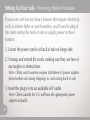
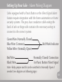
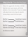
Safe & Vault Door User Manual
Congratulations on the purchase of your finely crafted
Brown Safe. We sincerely appreciate the trust your
purchase represents and take great pride in securely
protecting your treasured valuables.
Setting Up Your Safe
Selecting A Location
Powering Interior Features
Alarm Wiring Diagrams
Bolt Down Instructions
Concrete Floor
Wood Floor
Dial Lock
Operating Tips
Operating Instructions
Setting A New Combination
02
03
04
07
09
12
13
15
Electronic Lock
Operating Tips
Operating Instructions
Setting A New Combination
Changing Batteries
Sending Silent Distress Signal
Biometric Lock
20
21
22
23
24
*For CHRONOS Biometric see next section.
Operating Tips
Operating Instructions
Setting A Master Code
Enrolling A Fingerprint For First Time
Adding A New User
Changing Entry Method
Changing Batteries
25
27
29
31
33
37
40
CHRONOS Biometric Lock
Operating Tips
Operating Instructions
Setting A Master Code
Enrolling A Fingerprint
Turning On/Off Display Backlight
Changing Batteries – Chronos Round Display
Changing Batteries – Chronos Long Display
Vault Door - Electronic Lock with Dial Lock Back Up
Operating Tips
Operating Instructions
Electronic Lock - Setting A New Combination
Electronic Lock - Changing Batteries
Dial Lock - Operating Instructions
Inner Escape Device Operation
Panic Slide Latch Operation
43
45
47
49
52
53
55
57
59
60
61
62
63
65
3 Movement Mechanical Timelock
Operating Instructions
Timelock Release
Silent Signal Alert
Sending Signal Via Electronic Lock
Sending Signal Via Panic Button
Watch Winders
Programmable Watch Winders
Rotorwind Watch Winders
Watch Winder Carousel
Safe Interior
Adjusting Standard Interior Shelves
Adjusting Chronos Interior Shelves
Changing Drawer Inserts
Removing Drawer Detents
Removing Standard Drawers
Removing Undermount Drawers
67
68
69
70
71
77
83
85
87
89
91
93
95
Setting Up Your Safe
Thank you for purchasing!
As the premier manufacturer of high quality safes and vaults
built to a higher standard, Brown Safe commends your
decision to invest in protecting your valuables.
Please take a moment to review this information and begin
enjoying your new safe.
01
Setting Up Your Safe - Selecting A Location
Here are a few tips to keep in mind when selecting a location
for your new safe:
• Consider installing your safe in an accessible location where
you can conveniently access your valuables.
• Allow enough room for the door to fully open and allow for
unobstructed access to interior shelving and drawers.
• Avoid placing safe near foundation walls in a way that would
create a gap of 8”-18” whenever possible. This will eliminate
the ability to leverage the safe away from the wall using a
car jack to rip the safe’s base anchor bolts out of the flooring.
• Anchor the safe to the floor using the supplied anchor bolts.
See Bolt Down Instructions for step by step process.
02
Setting Up Your Safe - Powering Interior Features
If your new safe has any luxury features that require electricity,
such as interior lights or watch winders, you’ll need to plug in
the cords exiting the back of safe to supply power to those
features.
1. Locate the power cord(s) at back of safe on hinge side.
2. Unwrap and extend the cords, making sure they are free of
any tangles or obstructions.
Note: Orbita watch winders require attachment of power adapter
(stored within safe during shipping) to cord exiting back of safe.
3. Insert the plug(s) into an available A/C outlet.
Note: Clients outside the U.S. will have the appropriate power
adapter included.
03
Setting Up Your Safe - Alarm Wiring Diagram
Safes equipped with a Panic Button or the Silent Signal alarm
feature require integration with the home automation or home
security systems. The grey four conductor cable exiting the
back of safe on hinge side contains the necessary wiring to
connect to the correct system.
Green Wire (Normally Closed)
Blue Wire (Common)
Yellow Wire (Normally Open)
Red Wire
Black Wire
Bolt Work Indicator
(Normally Closed) Connection
for Panic Button/ Silent Signal
Note: Relay jumper switch can be switched to Normally Open if
needed (see diagram on following page).
04
Setting Up Your Safe - Alarm Wiring Diagram
The relay jumper switch is located under the boltwork cover
and can be positioned to Normally Open if necessary.
Note: Normally Closed is the default position.
Relay Jumper Position
Normally Closed (NC) - Right Position
Normally Open (NO) - Left Position
Alarm Cable Connector
05
Setting Up Your Safe - Chronos Alarm Wiring Diagram
Chronos Safes equipped with a Panic Button or the Silent
Signal alarm feature require integration with the home
automation or home security systems. The grey four conductor
cable exiting the back of safe on hinge side contains the
necessary wiring to connect to the correct system.
Black Wire (1)
Black Wire (2)
(Normally Open) Connection
for Bolt Work Indicator
Black Wire (3)
Yellow Wire (Green Stripe)
(Normally Open) Connection
for Panic Button/ Silent Signal
Note: Black wires are numbered
06
Bolt Down Instructions - Concrete Floor
1. Position safe in desired location and check for proper door
swing clearance, making sure it does not interfere with
interior drawers, concealment cabinetry, closet doors, etc.
2. When you are satisfied with the safes position, locate the
bolt holes in the bottom of the safe and drill a 5/8” hole
thru the right rear hole of the unit approximately ½” deeper
than the length of the anchor. Be careful not to drill
completely thru the slab.
*If necessary remove safe interior floor plate or bottom drawers
to expose bolt holes.
3. Clean hole of all excess concrete particles and dust.
4. With a bolt partly screwed into the anchor. Place it into
hole and gently tap it completely to the bottom of the
07 hole, then remove the bolt to expose the wedge.
Bolt Down Instructions - Concrete Floor
5. Set (expand) anchor by driving wedge down with a 3/8”
diameter pin punch thru center of anchor with a hammer
until it completely stops.
6. Place lock washer then flat washer on bolt and tighten
down to 50 foot-pounds of torque (tight).
7. Repeat steps 2-6 on each of the remaining bolt holes.
Caution:
*On safes too small to drill from inside, the holes will have
to be marked and drilled with the safe set aside and then
repositioned after the anchors are set.
*Great care should be taken to ensure the holes do not move
around as they are being drilled. It is often helpful to drill
3/16” pilot holes to prevent hole from drifting.
08
Bolt Down Instructions - Wood Floor
1. Position safe in desired location and check for proper door
swing clearance, making sure it does not interfere with
interior drawers, concealment cabinetry, closet doors, etc.
2. When you are satisfied with the safes position, locate the
bolt holes in the bottom of the safe and drill a 3/8” hole
through the right rear hole of the unit approx. 2½” deep.
*If necessary remove safe interior floor plate or bottom drawers
to expose bolt holes.
3. Place lock washer, then flat washer on bolt and tap gently
to start bolt into hole, then tighten down until snug. Take
care to not over tighten.
4. Repeat steps 2-6 on each of the remaining bolt holes.
09
Bolt Down Instructions - Wood Floor
Caution:
*On safes too small to drill from inside, the holes will have
to be marked and drilled with the safe set aside and then
repositioned after the anchors are set.
*Great care should be taken to ensure the holes do not
move around as they are being drilled. It is often helpful
to drill 3/16” pilot holes to prevent hole from drifting.
10
Dial Lock
The ideal choice for the traditionalist, the dial lock is a reliable and
elegant means of providing secure access to your safe.
No electronics means no maintenance, guaranteeing that you’ll have
years of trouble-free dependability.
Mechanical Dial Lock Features:
• Three combination wheels produces 1,000,000 possible
combinations
• Integral relock trigger sets off relockers if lock is
tampered with or punched.
• Brass wheels and lever offers long & dependable lock life.
•Dialing tolerance = +/- .5 degrees
11
Dial Lock - Operating Tips
Please keep these tips in mind when utilizing your dial lock:
1. Always use the line at the 12 o'clock position when dialing
your combination. This line is known as the opening index.
(See Figure 1. on page 14)
2. Prior to opening the safe make sure the handle is turned
completely to the locked position.
Right side hinges = handle should be fully counter-clockwise.
Left side hinges = handle should be fully clockwise.
3. Avoid putting pressure on the handle during combination entry
as this may cause a locking bolt malfunction.
4. Once the correct combination is entered turn handle to open position.
Right side hinges = Turn handle clockwise to open.
Left side hinges = Turn handle counter-clockwise to open.
5. In the open position the safe’s handle will rotate
approximately 20 degrees.
12
Dial Lock - Operating Instructions
1.
Turn the dial left (CCW) passing the first number in
the combination three times. Then stop exactly on
the number the fourth time.
2.
Turn the dial right (CW) passing the next number in
3x the combination two times. Then stop exactly on
the number the third time.
3.
Turn the dial left (CCW) passing the last number in
2x the combination one time. Then stop exactly on the
number the second time.
4.
Turn dial to the right (CW) until the dial completely
1x
stops (one revolution or less).
5. Turn safe handle to unlock and open door.
13
4x
Dial Lock - Operating Instructions
Opening Index
4x
Turn Left 4 times
3x Turn Right 3 times
2x
Turn Left 2 times
1x Turn Right 1 time or less
to unlock
Figure 1.
14
Dial Lock - Setting A New Combination
*To change the combination, you will need to know the existing
combination and have a La Gard change key (p/n 1307).
Caution: When selecting a combination, choose a three number
sequence from 0 - 99. Never select numbers 89 to 20 as the last
number of the combination. This is the “Forbidden Zone” and can
cause the lock to malfunction.
For security purposes, do not select a combination easily attained
from personal data such as birth date, phone number, etc.
1. Dial the existing combination using the line at the
11 O'clock position when dialing your combination.
This line is known as the changing index. (Figure 2.)
2. STOP the dial on the third number of the combination
15
Dial Lock - Setting A New Combination
3. Insert the change key into the change key hole. (Figure 3.)
Note: If the change key does not go in easily, the wheels are
not aligned. Repeat steps 1 - 3.
Changing Index
Change Key Hole
Figure 2.
Figure 3.
16
Dial Lock - Setting A New Combination
4. Turn the change key to the right (CW) one-quarter turn until
the key stops. Leave the change key in the lock while setting
the new combination.
5. Next turn the dial to the left (CCW) at least four complete
rotations to clear the lock. The lock is now ready to accept
the new combination.
Caution: Do not spin the dial to clear the lock.
6. Set the new combination using the changing index at the
11 O'clock position:
4x
17
Turn the dial left (CCW) passing the first number
in the combination three times. Then stop exactly on
the number the fourth time.
Dial Lock - Setting A New Combination
3x
2x
Turn the dial right (CW) passing the next number in
the combination two times. Then stop exactly on the
number the third time.
Turn the dial left (CCW) passing the last number in
the combination one time. Then stop exactly on the
number the second time.
7. Hold the Dial to prevent movement and turn the change
key to the left (CCW) one quarter turn.
8. Remove the change key. The new combination is now set.
9. Test the new combination several times with the door open
before locking the safe.
18
Electronic Lock
The electronic lock is our most popular lock due to its simplicity and
ease of use. This industrial grade keypad lock offers convenience
second to none and has proven it's worth over many years of both
commercial and residential service.
Electronic Lock Features:
• U. L. listed - Group 2 high security lock
• Wrong try penalty initiates lockout mode for 5 minutes
after 3 incorrect entry codes.
• External battery compartment is conveniently accessible
under keypad and utilizes standard 9-volt batteries.
• Made in the U.S.A.
19
Electronic Lock - Operating Tips
Please keep these tips in mind when utilizing your electronic lock:
1. After 3 incorrect entry codes the lock will timeout for 5 minutes.
2. Avoid putting pressure on the handle during combination entry
as this may cause a locking bolt malfunction.
3. Once the correct combination is entered you’ll have 3 seconds
to turn the safe’s handle.
4. Prior to opening the safe make sure the handle is turned
completely to the locked position.
Right side hinges = handle should be fully counter-clockwise.
Left side hinges = handle should be fully clockwise.
5. In the open position the safe’s handle will rotate approximately
20 degrees.
20
Electronic Lock - Operating Instructions
1. Enter 6 digit combination using lock keypad.
The lock will signal a valid combination entry with a double signal.
2. Turn safe handle to unlock and open door.
Note:
• Repeated beeping during an opening indicates that the
battery is low and should be replaced.
• Invalid combination entry: Lock signals three times.
• Wrong try penalty entry of three consecutive invalid
combinations will initiate a 5 minute lock out period,
during which time the LED flashes red at 10 second interval.
21
Electronic Lock - Setting A New Combination
*Always change combination with door open
1. Enter six zeros.
2. Enter existing 6 digit combination.
3. Enter new 6 digit combination two times consecutively.
4. *Before closing door* Test new combination to verify
proper operation.
Note: Locking bolts need to be retracted prior to shutting door.
22
Electronic Lock - Changing Batteries
1. Remove keypad by gently lifting straight up and tilting back.
*Caution keypad cable only has a few inches of free length.
2. Connect one 9-Volt Alkaline battery (Duracell only) to each
battery clip.
3. Insert batteries into bottom of housing.
4. Replace by placing the keypad on its mounting pins and
sliding down until keypad is firmly locked into position.
23
Electronic Lock - Sending Silent Distress Signal
*Only available if silent signal alarm lock feature was purchased.
1. To trigger silent signal alarm, enter existing combination
varying the last digit up by one number.
Example:
Standard Combination:
To Trigger the Alarm:
1-2-3-4-5-6
1-2-3-4-5-7
Note: This will open the safe as usual, but will send the
silent duress signal to the authorities.
24
Biometric Lock - Operating Tips
The Biometric Lock offers the ultimate in security and convenience.
Without a combination to remember or to be compromised, all that’s
necessary to securely gain access to the safe is your fingerprint.
Please keep these tips in mind when utilizing your biometric lock:
1. Press any button to turn on the lock.
2. The Master Code must contain 8 digits or letters.
3. The Master Code is only used for programming.
It does NOT unlock the safe.
4. All User Codes must contain 6 digits or letters.
5. Keep the safe door in the open position when changing the
lock code or fingerprint, and check lock function several times
before closing the safe door.
25
Biometric Lock - Operating Tips
6. Periodically clean the fingerprint sensor with a dry cloth to
ensure accurate readings.
7. Avoid putting pressure on the handle during combination entry
as this may cause a locking bolt malfunction.
8. Once the correct combination is entered you’ll have approx.
four (4) seconds once code is accepted (lock displays:
LOCK OPEN) to turn the safe’s handle.
9. Prior to opening the safe make sure the handle is turned
completely to the locked position.
Right side hinges = handle should be fully counter-clockwise.
Left side hinges = handle should be fully clockwise.
10. In the open position the safe’s handle will rotate approximately
20 degrees.
26
Biometric Lock - Operating Instructions
Unlocking with User Code
1. Press any button, lock will display ENTER CODE.
2. Enter 6 digit code, it will signal twice and display LOCK OPEN
3. Turn handle and open door.
Note: Do not apply pressure to handle prior to lock display
stating LOCK OPEN.
Note: The lock will remain unlocked for 4 seconds to allow time
to open the safe, after which it will automatically re-lock once
the handle is turned back to the locked position.
27
Biometric Lock - Operating Instructions
Unlocking with Fingerprint
*This function can only be used once a finger is enrolled
and the entry method is set to a fingerprint reading mode.
1. Press P (or button on front of lock housing), the lock will
beep twice, then press P again.
2. Place finger on sensor (lock will signal with one short beep,
followed by two long beeps).
3.Turn handle and open door.
Note: Do not apply pressure to handle prior to lock display
stating LOCK OPEN.
Note: The lock will remain unlocked for 4 seconds to allow time
to open the safe, after which it will automatically re-lock once
the handle is turned back to the locked position.
28
Biometric Lock - Setting Master Code
1. Press any button to turn on lock.
2. Press and hold 0 digit until displays reads MASTER CODE.
3. Enter 0 digit eight (8) times.
4. Enter your existing eight (8) digit Master Code one time.
5. Enter your NEW eight (8) digit Master Code two times.
If a valid code is entered the display will show
MASTER CODE UPDATED.
Note: Test lock operation several times before closing the door.
In case of a mistake, display will show CONFIRM CODE, NOT
MATCH and the old code will still be valid. Wait thirty seconds
and repeat steps above.
29
Biometric Lock - Setting User Code
1. Press any button to turn on lock.
2. Enter 0 digit six (6) times when displays reads ENTER CODE.
3. Enter your existing six (6) digit User Code one time.
4. Enter your NEW six (6) digit User Code two times.
If a valid code is entered the display will show
CODE CHANGED!
Note: Test lock operation several times before closing the door.
In case of a mistake, display will show CONFIRM CODE, NOT
MATCH and the old code will still be valid. Wait thirty seconds
and repeat steps above.
30
Biometric Lock - Enrolling Fingerprint for the First Time
1. Press any button, lock will display Enter Code.
2. Press and hold 0 digit until displays reads Master Code.
3. Enter 8 digit master code.
4. Press P six (6) times to select the User Menu, the display
will show USERS ON/OFF?
5. Press OK to view the User status, the display will show
USERS ON/OFF, (XX - XX).
6. Enter User ID 02, display will show USER ID = 2, DISABLE?
7. Press P four (4) times, display will show
USER ID = X, RE-ENROLL?
8. Press OK, display will show FINGERPRINT NUMBER = 1.
31
Biometric Lock - Enrolling Fingerprint for the First Time
9. Press OK, the display will show, SCAN YOUR FINGER then
2nd SCANNING and then 3rd SCANNING.
• Finger should be lifted after each scan, then quickly
replaced so that three separate scans are made.
10. Once scanning is completed, the display will show
ANOTHER FINGER.
• The system offers the option of scanning up to three (3)
fingers for each User or the Manager.
• Repeat this procedure for each fingerprint to be enrolled
for this User.
11. Press OK to confirm and enroll another fingerprint or P to
exit, display will show FINGERPRINT, SUCCESS.
Congratulations you have successfully enrolled a fingerprint!
32
Biometric Lock - Adding a New User
1. Press any button, lock will display ENTER CODE.
2. Press and hold 0 digit until displays reads MASTER CODE.
3. Enter 8 digit master code.
4. Press P six (6) times to select the User Menu, the display
will show USERS ON/OFF?
5. Press OK to view the User status, the display will show
USERS ON/OFF, (XX - XX).
6. Enter User ID (XX) of 03 or greater, display will show
USER ID = X, INSTALL?
7. Press OK to install User, the display will show
NEW CODE, X-X-X-X-X-X.
33
Biometric Lock - Adding a New User
8. Enter a new six (6) digit code, display will show
CONFIRM NEW, X-X-X-X-X-X.
9. Enter new six (6) digit code a second time to confirm,
display will show ACCESS LOCK, -----.
Note: If the lock is set to Code Only, steps 10 and 11 will
not appear. Fingerprint mode needs to be enabled before
you can enroll a fingerprint. Please refer to the directions for
Changing Operating Modes to enable fingerprint scanning.
10. Enter 1 and press OK, display will show FINGERPRINT
NUMBER = 1 then SCAN YOUR FINGER.
Continue to the next page for additional instructions.
34
Biometric Lock - Adding a New User
11. Place finger on the reader. It will beep once and begin
scan, then the lock will beep again and the display will
show, 2nd SCANNING, followed by the final beep and
3rd SCANNING.
Note: Finger should be lifted after each scan, then quickly
replaced so that three separate scans are made.
12. Once scanning is completed, the display will show
ANOTHER FINGER?
• The system offers the option of scanning up to three (3)
fingers for each User or the Manager.
• Repeat this procedure for each fingerprint to be enrolled
for this User.
35
• Note: If safe/vault is equipped with Silent Signal Alarm the 3rd
finger enrolled will be used as the “duress finger”.
Biometric Lock - Adding a New User
13a. Standard Locks (not equipped with silent signal alarm):
Press OK to confirm and enroll another fingerprint or
P to bypass, display will show USER IS, MANAGER?
13b. Locks Equipped with Silent Signal Alarm:
Press OK to confirm and enroll 2nd fingerprint.
Press OK to confirm and enroll 3rd fingerprint.
Once the 3rd finger is enrolled display reads:
FINGER 3 IS DURESS?
14. Press OK to accept or P to bypass, display will show,
TIME DELAY, OVERRIDE?
15. Press OK to accept or P to bypass, display will show,
USER = X, INSTALLED!
Congratulations you have successfully added a new User!
36
Biometric Lock - Changing Entry Method
1. Press any button, lock will display ENTER CODE.
2. Press and hold 0 digit until displays reads MASTER CODE.
3. Enter 8 digit master code.
4. Press P five (5) times to SYSTEM SETUP.
5. Press OK to select this function, display will show
LOCK INSTALL.
6. Press P three (3) times, display will show
SYSTEM OPER. MODE.
7. Press OK to enter the Menu, display will show
USER CODE.
37
Biometric Lock - Changing Entry Method
8. Press P to scroll through operation options.
Standard operating modes:
• USER CODE (default): 6 digit code is used to open lock.
• FINGER ONLY: A fingerprint is used to open lock.
Optional operating modes:
• 2 USER CODE: Two user codes must be used to open lock.
• FINGER + CODE: Both a fingerprint and user code must be
used to open lock.
• 2FINGERS: Two fingerprints must be used to open lock.
• 2FINGERS + CODE: Two fingerprints and a user code must
be used to open lock.
38
Biometric Lock - Changing Entry Method
9. After scrolling to appropriate operation, press OK to select,
display will show SYSTEM OPER. MODE.
10. Press P three (3) times to esc from menu.
11. Press OK to select, display will show SYSTEM SETUP.
12. Press P four (4) times, display will show
Do YOU WANT TO QUIT?
13. Press OK.
Your desired entry method is now set.
39
Biometric Lock - Changing The Batteries
How to recognize when the lock batteries need replacing:
• Lock will display WARNING! BATTERY LOW
Note: If lock continues to show WARNING! BATTERY LOW after
batteries are replaced. Enter combo and unlock safe to reset.
• If you notice a distinct change in the pitch of the beeps.
• Erratic or inconsistent lock operation.
• If the lock beeps 20 times rapidly when you try to open it,
but remains locked, then it is time to change the batteries.
Continue to the next page for instructions.
40
Biometric Lock - Changing The Batteries
1. Open the front access door of the entry display to reveal
the lock keypad and battery compartment covers.
2. Unscrew the allen bolts on both sides of the lock
keypad which secure the faceplates of the two battery
compartments.
Note: 1/16” hex driver included with safe.
3. Remove the faceplates of both battery compartments.
4. Unsnap the wired leads and replace the two 9-volt
alkaline batteries.
5. Insert batteries back into compartment and Re-attach
faceplate cover with the two allen bolts.
41
Biometric Lock - Changing The Batteries
Note: If lock continues to show WARNING! BATTERY LOW after
batteries are replaced. Enter combo and unlock safe to reset the lock.
Battery Compartment
Allen Bolts
9-Volt Battery
Battery Compartment
Faceplate
9-Volt Battery
WARNING!
BATTERY LOW
A
BCD
2
3
E
FGH
IJK
P
LMN
OPQ
RST
UVW
XYZ
OK
1
6
7
8
4
9
5
0
42
CHRONOS Biometric Lock
The Biometric Lock offers the ultimate in security and convenience.
Without a combination to remember or to be compromised, all that’s
necessary to securely gain access to the safe is your fingerprint.
Please keep these tips in mind when utilizing your biometric lock:
1. Begin all code entry or programming processes by pressing
the S T A R T button.
2. All codes must contain 6 digits or letters.
Note: Any digit or letter can be used as many times as you wish.
3. Press the
key after entering your code to signal the lock
you have finished entering all the digits.
#
4. If an incorrect digit was entered press the
last digit entered.
43
* key to erase the
5. Keep the safe door in the open position when changing the
lock code or fingerprint, and check lock function several times
before closing the safe door.
CHRONOS Biometric Lock - Operating Tips
6. Periodically clean the fingerprint sensor with a dry cloth to
ensure accurate readings.
7. After approximately 10 seconds of inactivity the keypad will
automatically turn off.
8. Avoid putting pressure on the handle during combination entry
as this may cause a locking bolt malfunction.
9. Once the correct combination is entered you’ll have 6 seconds
to turn the safe’s handle.
10. Prior to opening the safe make sure the handle is turned
completely to the locked position.
Right side hinges = handle should be fully counter-clockwise.
Left side hinges = handle should be fully clockwise.
11. In the open position the safe’s handle will rotate approximately
20 degrees.
44
CHRONOS Biometric Lock - Operating Instructions
Opening The Biometric Lock In Either Fingerprint or PIN Mode
1. Press the
S TA R T
button.
Note: After about 1.5 seconds the display will prompt you to
place finger or enter PIN and the keypad’s green LED will light up.
2. Place your finger on the sensor until the green LED goes off,
or enter your 6-digit PIN followed by the
button.
#
Note: If an incorrect digit was pressed while entering your
6-digit PIN press the
* key to erase the last digit entered.
45
CHRONOS Biometric Lock - Operating Instructions
3. The display will read LOCK OPEN.
Note: Do not put any pressure on the safe handle until after
the LCD displays LOCK OPEN.
4. Turn safe handle fully and open door.
Note: The lock will remain unlocked for 6 seconds to allow time
to open the safe, after which it will automatically re-lock once
the handle is turned back to the locked position.
46
CHRONOS Biometric Lock - Setting Master Code
1. Press
S TA R T
2. Press * and enter your lock’s default master code
followed by the
key.
#
5. Press
6. Press
47
2ABC
* or
2ABC
to scroll to Lock Setup
on keypad to open Lock Setup
#
4. Press
* or
#
3. Press
to scroll to Lock Program
on keypad to open Lock Program
CHRONOS Biometric Lock - Setting Master Code
8. Press
* or
3DEF
#
7. Press
to scroll to Master Code
on keypad to select Master Code
9. Display will prompt you to enter your new six digit master
code followed by the
key.
#
10. Then you will be prompted to enter the new master code
followed by the
key again.
#
11. The red light will blink several times and display
New Master Code Set
48
CHRONOS Biometric Lock - Enrolling A Fingerprint
1. Press
S TA R T
2. Press * and enter your lock’s default master code
followed by the
key.
#
Note: If you have not yet set your own master code,
then enter the default master code.
5. Press
49
3DEF
to scroll to Fingerprint Setup
on keypad to open Fingerprint Setup
* or
#
4. Press
* or
#
3. Press
to scroll to Enroll
CHRONOS Biometric Lock - Enrolling A Fingerprint
2ABC on keypad to open Enroll
7. Enter a user ID followed by the
key
#
6. Press
*Each fingerprint must be associated with a numerical position.
Example: Entering 1# would enroll your fingerprint in the 1st
position and 2# in the 2nd position.
#
8. Enter User Code followed by the
key
Note: You can set the user code to be the same as the master
code. The code associated with the 1st position is always the
master code. The user code associated with each fingerprint
will also open safe if the fingerprint is unavailable.
9. The green light will illuminate as you are prompted to
place your finger on the sensor.
10. Next the display will prompt you to remove your finger.
50
CHRONOS Biometric Lock - Enrolling A Fingerprint
11. Repeat Steps 9 & 10 two more times when prompted by
the display.
Note: The Sensor will take a total of three readings of
your fingerprint.
12. When finished the display will read Enrolled Successfully
51
CHRONOS Biometric Lock - Turning On/Off Backlight
S TA R T
2. Press
* and enter your code followed by the
to scroll to Display Setup
* or
6. Press
7. Press
keypad to open Display Setup
* or
to scroll to LCD Backlight
2ABC on keypad to select LCD Backlight
* or
#
5. Press
1Q
#
4. Press
key
#
3. Press
#
1. Press
to scroll to Enable or Disable
4. Press 1 Q on keypad to select Enable or press
keypad to select Disable
2ABC
on
52
CHRONOS Biometric Lock - Changing The Batteries
Chronos - Round Display
1. Open the front access door of the entry display to reveal
the lock keypad and battery compartment cover.
2. Unscrew the two allen bolts below the lock keypad which
secure the faceplate of the battery compartment.
Note: 1/16” hex driver included with safe.
3. Remove the faceplate of the battery compartment.
4. Unsnap the wired leads and replace the two 9-volt
alkaline batteries.
5. Insert batteries back into compartment and Re-attach
faceplate cover with the two allen bolts.
53
CHRONOS Biometric Lock - Changing The Batteries
How to recognize when the lock batteries need replacing:
• If you notice a distinct change in the pitch of the beeps.
• Erratic or inconsistent lock operation.
• If the lock beeps 20 times rapidly when you try to open it,
but remains locked, then it is time to change the batteries.
Battery Compartment
Faceplate
Battery Compartment
Allen Bolts
Display Access Door
S TA R T
54
CHRONOS Biometric Lock - Changing The Batteries
Chronos - Long Display
1. Open the front access door of the entry display to reveal
the lock keypad and battery compartment cover.
2. Unscrew the four allen bolts below the lock keypad which
secure the faceplate of the battery compartment.
Note: 1/16” hex driver included with safe.
3. Remove the faceplate of the battery compartment.
4. Unsnap the wired leads and replace the two 9-volt
alkaline batteries.
5. Insert batteries back into compartment and Re-attach
faceplate cover with the two allen bolts.
55
CHRONOS Biometric Lock - Changing The Batteries
How to recognize when the lock batteries need replacing:
• If you notice a distinct change in the pitch of the beeps.
• Erratic or inconsistent lock operation.
• If the lock beeps 20 times rapidly when you try to open it,
but remains locked, then it is time to change the batteries.
Battery Compartment
Faceplate
Battery Compartment
Allen Bolts
Display Access Door
S TA R T
Battery Compartment
Allen Bolts
56
Vault Door Lock - Electronic Lock with Dial Lock Backup
Brown Safe vault doors utilize a highly secure double lock system for
controlling access. With this system an electronic keypad lock is used
as well as a mechanical dial lock to provide the user with the highest
degree of security and reliability.
Electronic Lock Features:
• U. L. listed - Group 2 high security lock
• Wrong try penalty initiates lockout mode for 5 minutes after 3
incorrect entry codes.
• External battery compartment is conveniently accessible
under keypad and utilizes standard 9-volt batteries.
57
Mechanical Dial Lock Features:
• 3 combination wheels produces 1,000,000 possible combinations
• Integral relock trigger sets off relockers if lock is tampered with
• Brass wheels and lever offers long & dependable lock life.
•Dialing tolerance = +/- .5 degrees
Vault Door Lock - Operating Tips
Please keep these tips in mind when utilizing your electronic lock:
1. After 3 incorrect entry codes the lock will timeout for 5 minutes.
2. Avoid putting pressure on the handle during combination entry
as this may cause a locking bolt malfunction.
3. Once the correct combination is entered you’ll have 3 seconds
to turn the safe’s handle.
4. Prior to opening the safe make sure the handle is turned
completely to the locked position.
Right side hinges = handle should be fully counter-clockwise.
Left side hinges = handle should be fully clockwise.
5. In the open position the safe’s handle will rotate approximately
90 degrees.
58
Vault Door Lock - Operating Instructions
1. Enter 6 digit combination using electronic lock keypad.
The lock will signal a valid combination entry with a double signal.
2. Turn combination dial one turn clockwise until dial stops.
Note: Dial normally stops between 10 and 90. Once code is
entered you have 3 seconds to turn Dial to open position.
Tip - Turn dial to 50 prior to entering combination to
facilitate a quick & easy turn to open position.
3. Turn safe handle to unlock and open door.
59
Note:
• Repeated beeping during an opening indicates that the
battery is low and should be replaced.
• Invalid combination entry: Lock signals three times.
• Wrong try penalty entry of three consecutive invalid
combinations will initiate a 5 minute lock out period,
during which time the LED flashes red at 10 second interval.
Vault Door Lock - Setting A New Combination
*Always change combination with door open
Electronic Lock
1. Enter six zeros.
2. Enter existing 6 digit combination.
3. Enter new 6 digit combination two times consecutively.
4. *Before closing door* Test new combination to verify
proper operation.
Note: Locking bolts need to be retracted prior to shutting door.
60
Vault Door Lock - Changing Batteries
1. Remove keypad by gently lifting straight up and tilting back.
*Caution keypad cable only has a few inches of free length.
2. Connect one 9-Volt Alkaline battery (Duracell only) to each
battery clip.
3. Insert batteries into bottom of housing.
4. Replace by placing the keypad on its mounting pins and
sliding down until keypad is firmly locked into position.
61
Vault Door Lock - Dial Lock Operating Instructions
*Always use the line at the 12 o'clock position when dialing your
combination. This line is known as the opening index.
1. Turn dial five times counter clockwise to your first
combination number.
2. Turn dial clockwise passing second combination number
twice and stopping on the number the third time.
3. Turn dial counter clockwise passing third combination
number once and stopping on the number the second time.
4. Turn dial clockwise until the dial completely stops
(one revolution or less).
5. Turn safe handle to open door.
Note: See pages 13-14 for a diagram.
62
Vault Door Lock - Inner Escape Device Operation
Brown Safe vault doors equipped with an inner escape device enable
the user to open the vault door from inside the vault. Follow the
instructions below to learn how to operate the inner escape device.
1. Unlock and open the cover of the inner escape device to
access the opening mechanism.
2. Locate the red lever
3. Move the red lever towards the opening side of vault door
until it stops.
4. Turn handle towards the opening side of vault
door until it stops and open door.
Note: Handle rotates approximately 90 degrees.
63
Vault Door Lock - Inner Escape Device Operation
Red Lever
64
Vault Door Lock - Panic Slide Latch Operation
Brown Safe vault doors equipped with a panic slide latch allow the
vault to be used as a panic room. Follow the instructions below to
engage a lock out feature from the interior of the vault.
1. Close the vault door and turn the handle to engage the
locking bolts.
2. Unlock and open the cover of the inner escape device to
access the locking mechanism.
3. Locate the yellow lever on the panic slide latch.
4. Move the yellow lever towards the opening side of vault
door until it stops.
65
Note: Take note that the yellow lever covers the locking
mechanism so that it can no longer move.
Vault Door Lock - Panic Slide Latch Operation
5. The vault door will now remain locked until the yellow
lever is moved back into the open position.
Yellow Lever
66
3 Movement Mechanical Timelock
1. Insert winding key through hole in timelock cover directly
below time movement.
Note: Be sure key is fully inserted before winding.
2. Rotate key to set desired amount of time the safe lock is to
remain inoperable.
Note: Each mark on the dial represents one hour.
3. Repeat steps 1-2 for each movement. Set the dials to the
same amount of time for redundancy.
4. Depress set switch in center of timelock cover to engage.
The timelock is now in the locked position.
Note: Once pressed and the door closed the safe cannot be
opened until the set amount of time has elapsed.
67
3 Movement Mechanical Timelock
Timelock Release: As a safety feature the timelock can be
changed to the unlocked position. A manual release pin is
located on the right side of the cover next to the engage
switch used to set the timelock. Slide the manual release
pin to the right to disengage the timelock.
Note: This only disengages the timelock operation. The
movements will not zero and will need to wind down the set
amount of time if a mistake in programming was made.
Winding Key
Set Switch
Release Pin
68
Silent Signal Alert
Triggered by either a hidden button or an alternate unlock entry
code, safes equipped with the silent signal alert feature interface
directly with the alarm or home automation system to send an
undetectable alert to notify security authorities in the event that
the safe owner is forced to open the safe against their will.
Sending a Distress Signal via Electronic Lock:
*Only available if silent signal alarm lock feature was purchased.
To trigger silent signal alarm function, enter existing
combination varying the last digit up by one number.
Example:
Standard Combination:
To Trigger the Alarm:
69
1-2-3-4-5-6
1-2-3-4-5-7
Note: See page 4 for initial silent signal setup guide.
Silent Signal Alert
Sending a Duress Signal via Hidden Panic Button:
1. Unlock safe and open door normally.
2. Locate hidden panic button on interior of door near the
locking bolts.
3. Press the hidden panic button to send an alert to your
home monitoring system to immediately notify security
authorities.
70
Watch Winder Operation - Programmable Winders
Orbita Programmable winders allow the user to designate winding
cycles of 650, 800, 950 or 1300 Turns Per Day, with a choice of
clockwise, counter-clockwise or automatic reversing rotation.
Mounting Watches:
1. Remove winder cup by pulling straight out from face of
watch panel.
2. Remove watch cushion from winder cup.
3. Securely mount watch to cushion and insert into winder
cup.
4. Replace winder cup back inside winder housing by
pushing straight in as you rotate the cup until it seats fully
in winder housing.
71
Note: Alternative size watch cushions are available if needed.
Watch Winder Operation - Programmable Winders
Watch Winder Cushion
Watch Winder Cup
72
Watch Winder Operation - Programmable Winders
Turning On/Off Power to Watch Winders:
* Each winder has its own independent power switch so that they
can be individually controlled.
1. Remove winder cup by pulling straight out from face of
watch panel.
2. Locate toggle switch inside winder housing.
3. Turning ON winder: Toggle toward the On (line) position to
supply power to the winder.
Turning OFF winder: Toggle toward the Off (circle) position
to disconnect power to that winder.
4. Replace winder cup so that it snaps firmly into place.
73
Watch Winder Operation - Programmable Winders
Power Switch
Dip Switches
74
Watch Winder Operation - Programmable Winders
Setting Programmable Watch Winders:
* The rotation direction and duration of movement for each watch
winder is controlled by dip switches located within each winder
housing.
1. Remove winder cup by pulling straight out from face of
watch panel.
2. Locate dip switches inside winder housing.
3. Set dip switches using the program settings appropriate for
your watch model.
75
Note: Winders come from the factory with a default setting of
800 Clockwise rotations per day.
Visit Orbita’s online watch database to find the correct settings
for specific watches at: orbita.com/database-search/
Watch Winder Operation - Programmable Winders
Programmable Watch Winder Settings:
Operating
Mode
500
Turns Per Day
650
800
Turns Per Day Turns Per Day
■
■
3
4
1
■
■
4
1
Clockwise
Rotation Only
■
■
1
2
Counterclockwise
Rotation Only
■
■
1
2
3
Automatic
Reversing
■
■
■
1
2
3
■
■
■
■
4
1
1300
Turns Per Day
Clockwise
Rotation Only
■
1
■
2
■
3
■
4
■
■
■
■
2
3
4
1
■
■
2
3
■
2
■
3
■
2
■
■
4
1
■
■
4
1
■
950
Turns Per Day
■
■
■
■
■
■
3
4
1
2
3
4
■
2
3
■
■
2
3
■
■
■
4
1
2
3
■
■
■
4
1
2
■
■
3
■
4
■
4
1300
Turns Per Day
■
■
■
■
1
2
3
4
Counterclockwise
Rotation Only
76
Watch Winder Operation - Rotorwind Modules
Orbita Rotorwind winders swing the watch, rather than rotating it,
mimicking the natural action of the wrist.
Mounting Watches:
1. Remove winder cup by pulling straight out from face of
watch panel.
2. Remove watch cushion from winder cup.
3. Securely mount watch to cushion and insert into winder
cup.
4. Replace winder cup back inside winder housing by
pushing straight in as you rotate the cup until it seats fully
in winder housing.
77
Note: Alternative size watch cushions are available if needed.
Watch Winder Operation - Rotorwind Modules
Watch Winder Cushion
Watch Winder Cup
78
Watch Winder Operation - Rotorwind Modules
Turning On/Off Power to Watch Winders:
* Each winder has its own independent power switch so that they
can be individually controlled.
1. Remove winder cup by pulling straight out from face of
watch panel.
2. Locate the red power detent switch inside the winder housing.
3. Turning ON winder: Press the switch in to supply power
to the winder.
Turning OFF winder: Press the switch again and the button
pops out to disconnect power to the winder.
4. Replace winder cup so that it snaps firmly into place.
79
Watch Winder Operation - Rotorwind Modules
Timing Interval
Switch
10
15
Power Switch
80
Watch Winder Operation - Rotorwind Modules
Unlike other watch winders which rotate a watch in order to wind it,
the Rotorwind modules gently swing the watch instead. A semicircular rotor, attached to the back of the mounting cup, is supported
by two free-turning precision ball bearings which enables the "back
and forth" motion when the cup is raised and then released from the
12 o'clock position at either 10 or 15 minute intervals.
10 Minute Interval – This is the default setting and causes the
watch to swing back and forth for several oscillations just as it
would if it were being worn on the wrist.
15 Minute Interval – This is the extended program and allows
many watches that wind in both directions to remain fully
wound while on the winder.
81
Watch Winder Operation - Rotorwind Modules
Setting The Timing Switch For 10 or 15 Minute Operation:
* Each winder has its own independent timing switch so that they
can be individually controlled.
1. Remove winder cup by pulling straight out from face of
watch panel.
2. Locate the black slide switch near the red power button
inside the winder housing.
3. Insert an object (screwdriver, pen, etc.) in the opening and
slide the switch lever down to select 15 minute intervals or
up to select 10 minute intervals.
4. Replace winder cup so that it snaps firmly into place.
82
Watch Winder Operation - Winder Carousel
The Winder Carousel groups watches circularly to maximize available
space and button activated motors quickly rotate the stack in either
direction for convenient access to timepieces.
1. Depress power switch to supply electricity to the carousel.
Note: This turns on power to the carousel only.
Winders are powered and controlled by their individual switches.
2. Depress carousel direction switch in the direction you
would like the carousel to turn.
Warning: Do not change directions while the carousel is moving.
If so the power switch must be turned off and then back on after
4 seconds to reset the carousel.
3. Depress the carousel operation switch to turn the carousel.
83
Note: Each time the button is pressed the carousel will turn to
the next set of winders and then stop. Press and hold the
operation switch to rotate the carousel continuously.
Watch Winder Operation - Winder Carousel
Winder Carousel Switches:
A
A Winder Power Switches
A
B Carousel Power Switch
C Direction Switch
D Operation Switch
A
B
C
D
84
Safe Interior - Adjusting Shelves
To accommodate our client’s specific needs and offer added
flexibility, all interior shelves are adjustable.
1. Open safe and remove all contents resting on shelf.
2. Remove shelf from safe interior.
Note: Begin by lifting up on one side of shelf if tightly fitted.
3. Once shelf is removed and the shelf support brackets are
visible, remove brackets by tilting up and pulling out.
4. Relocate the brackets to the desired location.
Note: Interior lining may need to be punctured to fit shelf bracket.
5. Replace shelf after all four supports brackets are securely
in place.
85
Safe Interior - Adjusting Shelves
Adjustable Shelf
Shelf Support Bracket
86
Safe Interior - Adjusting Chronos Shelves
* Chronos Shelves are supported by four allen bolts that fit in holes
spaced at 1” increments. The holes not in use have ¼-20 threaded set
screws in them.
1. Open safe and remove all contents resting on shelf.
2. Remove shelf from safe interior.
Note: Begin by lifting up on one side of shelf if tightly fitted.
3. Once shelf is removed the four allen bolts that support the
shelf will be visible, remove bolts using a 3/16” hex driver.
4. Remove set screws from desired shelf location using a
1/8” hex driver and replace in previous location.
5. Relocate the allen bolts to the desired location and replace
87 shelf once all four supports are securely in place.
Safe Interior - Adjusting Chronos Shelves
Adjustable Shelf
Allen Bolt Shelf Supports
Set Screws
88
Safe Interior - Changing Jewelry Drawer Inserts
In an effort to supply you with the most convenient solution to
organizing your valuables, Brown Safe has created a wide
selection of drawer insert layout options and designed them to
be interchangeable. Simply follow the instructions below to
replace or relocate your drawer inserts.
1. Fully extend jewelry drawer.
2. Remove drawer insert by grasping the interior of the layout
and lifting straight up from jewelry drawer.
3. Once the layout is removed relocate in an empty drawer by
centering the layout over the drawer and firmly pressing
downward.
89
Safe Interior - Changing Jewelry Drawer Inserts
Drawer Insert
Jewelry Drawer
90
Safe Interior - Removing Drawer Detents
Drawer detents are installed on jewelry drawers to protect
the drawers from damage during transit. These detents can
be removed if desired, eliminating the initial stiffness felt
when opening the jewelry drawers.
1. Fully extend jewelry drawer.
2. Remove jewelry drawer by pressing levers on sides of
drawer in specified direction (one up, one down).
3. Once drawer is removed, drawer detents will be visible at
the rear of the slide attached to the jewelry box unit. The
detent is black plastic and shaped similar to the numeral 8.
91
Safe Interior - Removing Drawer Detents
4. Drawer detents can be removed using a slot screwdriver
inserted into the space between the metal slide and the
plastic detent. The detent should pop off.
5. Insert drawers back onto drawer slides and fully close
(may be hard to close the first time).
Note: Drawer detents can be saved and used if the safe ever
needs to be moved.
92
Safe Interior - Removing Standard Drawers
Brown Safe’s Gem and Estate Series luxury safes make use of
top quality drawer slides to accommodate reliable and
convenient access to your valuables. These drawers can be
removed by following the directions below.
1. Fully extend jewelry drawer.
2. Locate release levers on both drawer slides.
Note: There is one lever on the left side of the drawer and one
lever on the right side of the drawer.
3. Remove jewelry drawer by lifting up on the left lever and
pressing down on the right lever while simultaneously
sliding the jewelry drawer out.
93
Safe Interior - Removing Standard Drawers
B
A
C
A Lift Up Left Lever
B Press Down Right Lever
C Pull Drawer Out
94
Safe Interior - Removing Undermount Drawers
Brown Safe’s Chronos Series and Man Safes make use of
refined undermount drawer slides to accommodate reliable
and convenient access to your valuables. These drawers can
be removed by following the simple directions below.
1. Fully extend jewelry drawer.
2. On the underside of the drawer, locate the 2 orange release
levers on both drawer slides.
3. Remove jewelry drawer by depressing the release levers
while simultaneously sliding the jewelry drawer out.
95
Safe Interior - Removing Undermount Drawers
Release Levers
96
If you have any questions about using your new safe or need
additional information please visit the Support Page at
www.BrownSafe.com or contact us directly at:
Phone - (760) 233-2293
Email - [email protected]
Enjoy the security, convenience, and peace of mind
that comes with owning a Brown Safe!
Brown Safe Manufacturing
1081 Poinsettia Ave.
Vista, CA 92081
United States
www.BrownSafe.com
Ph. (760) 233-2293
Fax: (760) 233-2297
Email: [email protected]