1
Neyfl,
fiz
1 -- s
()
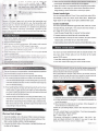
Testing Button
G)
'c'-
O
lndicator Light
C)
Battery
@
@
@
Hot snoe
s
?a=:- a:a, at --la. a lal,av aT erv!.a,Tmenl. lt might
=$... a.acq: :€ ta i:edee@s. However. this is rarely occurred
2 i.'.'..re €ble when it is connecting the trigge.
3 P ea* .e-cre the battenes for a long period of non-using the device.
4 \e,e-:-: ^c. store the paoduct in high temperature environment.
User Manual
5.
Kee. :-?se !n ts ln dry condition. Do not clean or touch the product
* :^ *e: raD or wel hands. Otheruise, it mav cause the unusual
pe{o-s cf camage of the device.
6 Ne!e. -se tre product jn flammable area such as gas station.
Oi:e-n-se : -ay €use an explosion or flre
etc_
Group switch button and indicior tighj
USBsocket
Channel switch button
Cl
1.
Testing Button
Press this button to test the flash on the device
Blue light represents the dev ce received the normal sional from the
l-e oev ce sent the rrgger srinal
3. Battery Compartment
FSK2.4GHz W reless System
lnstall 2pcs ofAA battery
4. Hot shoe
2.1'3.3V(Mx2 pieces)
3 Flxed Channel and
Caaaae
Op€?:Ea
g
f)HotShoemount @
transce,ver. red ltght reoresenls
T}?e:
gfolping
^E
Power Switch
S*itcr, Brtton
2. lndicator Light
E.{
Cc"r.
Compartment
3.5mm output socket
?tge:
1
Connectingtothecamera hotshoe mount orTTL line hot shoe
mount, receiving the camera wake-up and flash t.igger signal.
AutoChannel
5. Hot shoe mount
3
Connecting to the flash hot shoe. sendjng wake-up and trigger
signal to the flash
200m
Sr-: S:+-:
1 8000S(different
camera and flash model
6. 3.5mm
output socket
Output the trigger sig nal/sh utter signal th rou g h the con necti ng
cable with connecled the camera/studio lights.
W{
RF
, dffis.
-.
R@ie. :a:-:-_,
'i11i111$t
T€.s-:g
r_!,--::,:.
-rn-!ic.:
a;:?-r
:ac.ar 5--T -^,:e. sE-a-aj mcie
{!:-:, .:-= ,.:€sE-:-ar
(2O00mA)
7. Power Switch
ON: The device
Taae,2C00mAi
Slave
-624 lWireless Transceiver
As per the transceiver RF-6241C for canon as the example
o
+-{-
3.5-6.35 Flash Cable
#----4
3.5-3.5 Flash Cable
Shutter release cable
a
.E@EO :.s
:7
ptug
H;
@ Shufrer release plug
Support nine types of plug for different cameras.
@
@
o
Thank you so much for purchasing
l/eyin product. please read
the manual and understand the camera/flash operation carefully.
Through this manual, you can easily handle the operation
method and understand precauilons
on
OFF: The device off
8. Function button
o
the device is under transmit mode when this indicator
light is off, the device is under .eceive mode when th s
E
D
the device is under high speed sync mode when this
indicator light is on.
the device is under 2nd curtain sync mode when this
indicator light is on.
Remark: when the device is undertransmitting mode, IE!I and
(D I both lights are on means the device is under 1 st curtain
sync mode.
9. _Group switch button and indictor light
Represent the group which is under conjrol, user can maximum
controlling 3 groups in the same time but at least to control 1
grou p.
10. USB socket
1
For firmware upgrade
1. Channel switch
button
Able io set 1-3 fixed channels and 1 auto channel.
-@
:
Auto cha n ne I match i ng need to tu rn off the devices during the
operation. Switch the channel asAUTO on both transceivers.
2. Press and hold the testing button when the device is off and
then turn it on under auto channel mode, then the indicator liqht
will twinkle at his moment. ( Do the same process on another
device to complete the auto channel matching)
3. After transceivers done the channel matching, any extra pieces
'1 .
of devices added which is operate with the same way mentioned
on the above for the channel matching.
4. Turn offthe power, channel matching completed.
{
( i-:
I
I Stave
I
indicalor tight on means the device
D iHH,"*::":T:,j"',and rEI isnor
]{" E (c,,
t@ G)
sr.G
i..
El
-B
tr
.c
( S ave ) indicator light off means the
:.. :. : -::e. ransnil mode. I E I
.{€:tr €tt m l]Ens the devi@ is under
n€n speed syrc mode, A/B/C buttons
IlEos dtput signal function properly.
on
4. Make sure the transmitter efiective @ntrcl grcups inc{ude
@iver
current group, otheryise the receiverwill not be triggered.
5. Wake-up function is not supported when using the incomp-atible
transmitter The first image sync speed will be reduced;the second
image shooting in 30sec will be back to normal sync speed.
srl',.
E
ABC
IEI
E
indicator light on means the device
is under2nd curtain.
Control studio light
You can purchase additional 3.5mm-3.5mm studio flash cable,3.55 to
6.35 adapter, 3.5mm to 6.35mm studio flash cable. Receiver get
Remark: Wireless trigger work only when the transmitter and
receiver with the same group light on, e.g. the transmitter with
A group Iight on. receiver with A group light on so the device is
able to trigger the flash otherwise, it is unable to trig the flash
properly. Transmitter maximum controlling 3 groups at the
same time and each group is able to control more than one flash
at the same time.
trigger signal can sync trigger studio light by additional flash cable.
Control multi flash
You need to purchase additlonal triggerflash
eble, which can @ntrol
multi pass through, studio light or mix using the two kinds of flash, to
sync lrigger all the flash when shooting.
'1.
lnstall the pass through flash on receiver hot shoe socket.
2. Connect receiver and studio light with connecting cable.
Multi-button design, each function with individual button when
make the operation more simple
2- Support firmware update
3. With farlher controlling distance, 200 meters with normal
operation, maximum with 500 meters in open area.
4. With more combinations of output model, able to set each
group offlash with differeni output power
1.
5. With Iess pcre'cc-sirption
design and using gold plated
balter! compafrmea:.
6 With exlenoabie syac aulpJ: sac(et 1c: cil] abie tocont.ol
€rera si:@ting but also able to co.iic cuidoor flasi igii and
siudrc iighr
7. With artificial design of testing output pder
8. Support group controlling offlash focusing
1 Car
se: :ie exposure compensation, bracket exposure, aperture
and f@l length through the camera setting.
2. Also
6n
set the above functions through the flash setting
A. TTL mode and manual mode which need to set on flash setting
if never set the focal length on flash setting then you have to
reset the camera to be auto mode and set the focal length as
auto on the flash setting.
B. Focal Iength setting, the flash setting have priority on
the focal
length output, if never set the focal length on flash setting then
you have to reset the camera to be auto mode and set the focal
length as auto on the flash setting.
C. The flash output of test flash is according the flash setting. e.g
whenever the flash set as TTL mode, the ilash output of test
flash which is according tothe pre-flash output; wheneverthe
flash set as manual mode, the flash output oftest flash which
is according to manual setting.
Work as flash trigger
1. Check the installation; tum on the power
2. Half-press the shutter button of the
ofiash, GmeE and receiver
€mera, @mera willfocus.
lf
the
flash is under standby condition, it will be awakened.
3. Full-press the shutter button ofthe @mera,
the flash will be triggered.
it
will take the photo, and
3. lnstall transmitter on the top hot shoe of camera, full press camera
release button, all the flash will sync flash with camera.
4. Need matching cfiannel wih all he l@ive6 and haremitt€r before using.
You need to pruchase additional flash cable to using this function. We
have many kinds of flash cable and can fit almost all the market
popular DSLR camera.
1. lnsert flash cable plug into receiver output socket.
2. lnsert flash cable another plug into camera shutter socket.
Remark: when using RF-624 as the shutter remote, please don't
mount the device on top of the camera's hot shoe otherwise the
devices would not be function properly.
Due to the difference shutter of the camera, the shutter remote is
unable to function under the auto focus mode for some brands of
camera. lt can only function under manual focus mode.
ffiffiffi
1 - Check the camera's hot shoe weather is the same as the tra nsceiver
2. Putthe transceiver as diagram 1-2 as thearrowdirectionon
top of the camera
3. After mou nted the transceiver on camera, follow diagram 1 -3
arrow direction and fixed the screw.
Thanks for purchasing Meyin product and read this instruction
manual.
You can contact Meyin local distributor if you have any question
or justvisit Meyin official website:
hltp: / /www. meyin. com. cn
This manual information is updated at April, 131h,2013. You
need ask Meyin distributor for details if you want to use this
manual with the product which release later.
MSM006 V10.01