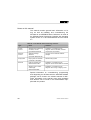
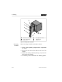
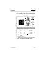
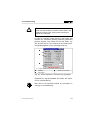
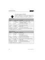
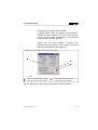
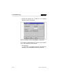
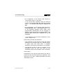
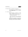
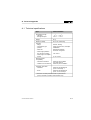
1
Smart Positioning Controller SPC200 Fieldbus module INTERBUS Typ SPC200-COM-IBS Author: Translation: Editors: Layout: Type setting: S. Breuer, E. Klotz Douglas Smith H.-J. Drung, M. Holder Festo AG & Co., Dept. KI-TD KI-TD Printed on 100 % recycled paper Edition: 9904NH SPC200-COM-IBS 9904NH (Festo AG & Co., D-73726 Esslingen, Federal Republic of Germany, 1999) The copying, distribution and utilization of this document as well as the communication of its contents to others without expressed authorization is prohibited. Offenders will be held liable for the payment of damages. All rights reserved, in particular the right to carry out patent, utility model or ornamental design registration. I Order no.: Description: Designation: II 188 891 Manual P.BE-SPC200-COM-IBS-GB SPC200-COM-IBS 9904NH Contents Designated use. . . . . . . . . . . . . . . . . . . . . . . . . . . . . . . . . . . . . . . . . . . . . . V Target group . . . . . . . . . . . . . . . . . . . . . . . . . . . . . . . . . . . . . . . . . . . . . . . VI Important user instructions . . . . . . . . . . . . . . . . . . . . . . . . . . . . . . . . . . . . VI Danger categories . . . . . . . . . . . . . . . . . . . . . . . . . . . . . . . . . . . . . . . . . . VI Notes on this manual . . . . . . . . . . . . . . . . . . . . . . . . . . . . . . . . . . . . . . VIII Product-specific terms and abbreviations . . . . . . . . . . . . . . . . . . . . . . . . IX 1. System summary 1.1 1.2 1.3 1.4 System structure . . . . . . . . . . . . . . . . . . . . . . . . . . . . . . . . . . . . . 1-3 Connecting and display elements on the INTERBUS module . 1-4 Basic structure for operation on the INTERBUS . . . . . . . . . . . . 1-5 Operating modes . . . . . . . . . . . . . . . . . . . . . . . . . . . . . . . . . . . . . 1-7 2. Fitting 2.1 Fitting and removing the field bus module. . . . . . . . . . . . . . . . . . 2-4 3. Installation 3.1 3.2 General instructions . . . . . . . . . . . . . . . . . . . . . . . . . . . . . . . . . . . 3-3 Connecting the INTERBUS interface. . . . . . . . . . . . . . . . . . . . . . 3-4 4. Commissioning 4.1 4.1.1 4.1.2 4.1.3 4.2 4.2.1 4.2.2 4.2.3 4.3 4.3.1 4.3.2 4.3.3 Procedure for commissioning. . . . . . . . . . . . . . . . . . . . . . . . . . . . 4-3 Additional instructions on commissioning with WinPISA . . . . . . . 4-4 Commissioning the field bus (summary) . . . . . . . . . . . . . . . . . . . 4-8 Configuring the I/O range for INTERBUS . . . . . . . . . . . . . . . . . . 4-9 Basic principles of configuration and addressing. . . . . . . . . . . . 4-12 General information . . . . . . . . . . . . . . . . . . . . . . . . . . . . . . . . . . 4-12 Number of configurable inputs and outputs on the SPC200-COM-IBS . . . . . . . . . . . . . . . . . . . . . . . . . . . . . . . . . . . 4-13 Addressing variants on the INTERBUS . . . . . . . . . . . . . . . . . . . 4-14 Bus configuration . . . . . . . . . . . . . . . . . . . . . . . . . . . . . . . . . . . 4-15 Bus configuration with CMD software . . . . . . . . . . . . . . . . . . . . 4-15 Bus configuration without CMD software. . . . . . . . . . . . . . . . . . 4-22 Switching on the power supplies on the INTERBUS. . . . . . . . . 4-24 SPC200-COM-IBS 9904NH III 4.4 4.4.1 4.4.2 4.4.3 4.4.4 4.5 4.5.1 4.5.2 4.5.3 Addressing the SPC200 on the INTERBUS . . . . . . . . . . . . . . General information . . . . . . . . . . . . . . . . . . . . . . . . . . . . . . . . . Summary of the I/O addresses of the SPC200-COM-IBS. . . . Entering process data via the CMD software . . . . . . . . . . . . . Preprocessing and periphery errors (PF). . . . . . . . . . . . . . . . . Programming examples for an S5.. . . . . . . . . . . . . . . . . . . . . . Basic principles. . . . . . . . . . . . . . . . . . . . . . . . . . . . . . . . . . . . . Handshake bits . . . . . . . . . . . . . . . . . . . . . . . . . . . . . . . . . . . . . Record select . . . . . . . . . . . . . . . . . . . . . . . . . . . . . . . . . . . . . . 4-25 4-25 4-28 4-30 4-33 4-34 4-34 4-36 4-39 5. Diagnosis and error treatment 5.1 5.2 5.3 5.4 General instructions on diagnosis . . . . . . . . . . . . . . . . . . . . . . . On-the-spot diagnosis . . . . . . . . . . . . . . . . . . . . . . . . . . . . . . . . Diagnosis via WinPISA . . . . . . . . . . . . . . . . . . . . . . . . . . . . . . . Interruption in field bus connection . . . . . . . . . . . . . . . . . . . . . . 5-3 5-4 5-5 5-6 A. Technical appendix A.1 A.2 IV Technical specifications . . . . . . . . . . . . . . . . . . . . . . . . . . . . . . . A-3 Index . . . . . . . . . . . . . . . . . . . . . . . . . . . . . . . . . . . . . . . . . . . . . . A-5 SPC200-COM-IBS 9904NH Designated use The field bus module type SPC200-COM-IBS has been designed for connecting the SPC200 to the INTERBUS. With this field bus module the SPC200 can be operated as a slave on the remote bus. The basic components and modules for the SPC200 are described in the User Manual type P.BE-SPC200-... You must observe at all costs the safety precautions described therein as well as the designated use of the individual components and modules. Please observe also the notes on safety in the operating instructions for the pneumatic components used. The SPC200 as well as the modules and cables to be connected may only be used as follows: – as intended – in their original state – without any modifications – in perfect technical condition If used with additional commercially-available components, such as sensors and actuators, the specified limits for pressures, temperatures, electrical specifications, torques, etc. must be observed. Local and national technical regulations must also be observed. SPC200-COM-IBS 9904NH V Target group This manual is directed exclusively at technicians trained in control and automation technology and who have experience in installing, commissioning, programming and diagnosing INTERBUS slaves. Important user instructions This manual contains instructions on possible dangers which can occur if the SPC200 is not used correctly. These instructions are printed in italics, are placed in a frame and also marked with a pictogram. Danger categories A distinction is made beween the following: WARNING: This means that considerable injury to people and/or damage to property can occur if these instructions are not observed. CAUTION: This means that injury to people and/or damage to property can occur if these instructions are not observed. PLEASE NOTE: This means that damage to property can occur if these instructions are not observed. VI SPC200-COM-IBS 9904NH Pictograms Pictograms and symbols supplement the danger instructions and draw attention to the nature and consequences of dangers. The following pictograms are used: Uncontrolled movements of loose tubing Unintentional movements of the connected actuators High electric voltage or undefined switching status of the electronic components which consequently affects connected circuits. Electrostatically vulnerable components which will be damaged if the contacts are touched. Recommendations and tips are marked with this pictogram. Text markings • This point marks activities which can be carried out in any order. 1. Numbers denote activites which must be carried out in the sequence listed. – Hyphens denote general activities. SPC200-COM-IBS 9904NH VII Notes on this manual This manual contains general basic information on fitting as well as installing and commissioning the SPC200 as an INTERBUS slave. Reference is made to the SPC200 Smart Positioning Controller with operating system version V 3.x and with WinPISA as from version 3.x. Manuals on the SPC200 Smart Positioning Controller Type Name Contents System manual SPC200 Smart Positioning Controller, manual type P.BE-SPC200-GB Installation, commissioning and diagnosis with the SPC200; standard components and modules Software manual Software package WinPISA type P.SW-WIN-PISA-GB Functions of the WinPISA software package Help system Help system for WinPISA (contained in WinPISA) WinPISA help system Manuals Field bus module type P.BE-SPC200-COM-... Installation, commissioning and diagnosis of the relevant field bus module Stepping motor indexer module type P.BE-SPC200-SMX-... Installation, commissioning and diagnosis when using a stepping motor Special information on commissioning, programming and diagnosing the SPC200 with the WinPISA software package can be found in the relevant manual for WinPISA. Information on the electric axes, drive packages and sensors can be found in the documentation supplied with the product. VIII SPC200-COM-IBS 9904NH Product-specific terms and abbreviations The following product-specific terms and abbreviations are used in this manual: Term/ abbreviation Meaning Modules Cards which are plugged into the rack of the SPC200 I/Os I Digital input IBS INTERBUS (remote bus) Q Digital output PLC/IPC Programmable logic controller / industrial PC SPC200-COM-IBS 9904NH IX X SPC200-COM-IBS 9904NH 1. System summary Chapter 1 System summary SPC200-COM-IBS 9904NH 1-1 1. System summary Contents 1. System summary 1.1 1.2 1.3 1.4 1-2 System structure . . . . . . . . . . . . . . . . . . . . . . . . . . . . . . . . . . . . Connecting and display elements on the INTERBUS module Basic structure for operation on the INTERBUS . . . . . . . . . . . Operating modes . . . . . . . . . . . . . . . . . . . . . . . . . . . . . . . . . . . . 1-3 1-4 1-5 1-7 SPC200-COM-IBS 9904NH 1. System summary 1.1 System structure Special field bus modules are available for connecting the SPC200 to field bus systems. Field bus module type SPC200-COM-IBS enables the SPC200 to be connected to the INTERBUS. With this module the SPC200 can be operated on the remote bus. 2 1 2 INTERBUS 3 4 1 PC with suitable software for: - the INTERBUS configuration (CMD-SW) - programming the IBS master - configuring the SPC200 (WinPISA) 5 with IBS module 2 Controller/IPC as INTERBUS slave 3 SPC200 terminal on the INTERBUS 4 Valve (example) 5 Further slaves on the INTERBUS Fig. 1/1: System summary of SPC200 on the INTERBUS (example) SPC200-COM-IBS 9904NH 1-3 1. System summary 1.2 Connecting and display elements on the INTERBUS module The diagram below shows the connecting and display elements on field bus module type SPC200-COM-IBS. 1 2 3 1 2 4 3 5 6 INTERBUS incoming RD LED (red) TR LED (green) 4 5 6 RC LED (green) BA LED (green) INTERBUS continuing Fig. 1/2: Connecting and display elements 1-4 SPC200-COM-IBS 9904NH 1. System summary 1.3 Basic structure for operation on the INTERBUS Basic structure for INTERBUS The SPC200 can function as a remote bus slave with just the following modules. 1 1 2 3 2 3 Power supply module Diagnostic module Field bus module for INTERBUS Fig. 1/3: Basic structure for INTERBUS SPC200-COM-IBS 9904NH Module Description Power supply module Enables both the power supply and the axis interface designed as a field device to be connected. Diagnostic module Enables the operating panel to be inserted (optional) and a PC to be connected. Field bus module for INTERBUS Enables connection and communication via the field bus. 1-5 1. System summary A system with the above-mentioned modules offers the following scope of performance: • control of up to two pneumatic axes. • programming and diagnosis via a PC or an operating panel. • Coordination with external PLC/IPC via field bus. With field bus module type SPC200-COM-IBS, the SPC200 can be connected as a remote bus slave on the INTERBUS. The SPC200 can be controlled via the INTERBUS in the operating modes start/stop or record select. The field bus module provides the address range required for this. 1-6 SPC200-COM-IBS 9904NH 1. System summary 1.4 Operating modes Whether for control via an I/O module or via a field bus, the SPC200 offers the following operating modes for processing the stored NC programs: • start/stop mode • record select mode The desired operating mode can be set with the control panel or with WinPISA. Detailed information on the operating modes can be found in the user manual for the SPC200. The SPC200 communicates with the INTERBUS master via the internal I/O address ranges (internal input/output addresses) of the field bus module. Depending on the operating mode used, field bus module type SPC200-COM-IBS provides the following I/O bits for communication with the INTERBUS master: Operating mode I/O address range of field bus module type SPC200-COM-IBS Start/Stop I10.0 - I13.15*) **) Q10.0 - Q13.15*) Record select **) I10.0 - I11.15*) Q10.0 - Q10.15*) *) **) Address specification as seen by the SPC200 1-4 process data words can be configured CAUTION The outputs of the INTERBUS master are mapped on internal inputs of the field bus module or of the SPC200. SPC200-COM-IBS 9904NH 1-7 1. System summary PLC/IPC INTERBUS INTERFACE SPC200-COM-IBS I10.0 ... I13.15 1 2 4 5 4 5 3 5 4 6 Q10.0 ... Q13.15 1) User program in the higher-order PLC/IPC Communication module/bus module (IBS master) User program in the SPC200 Outputs Inputs 6 7 8 9 5 4 1) 7 1 2 3 4 5 SPC200 1) 8 9 INTERBUS (remote bus) Internal I/Os of the field bus module Time for cyclic data exchange Internal I/Os of the SPC200 Maximum address range; Address specification as seen by the SPC200 Fig. 1/4: Internal I/O address range Due to the large I/O address range, considerably more NC records can be accessed in record select mode via the field bus, than via the I/O module. With the field bus module, 10 bits are available for selecting the NC record number in record select mode. The maximum permitted number of NC records (up to 1000) of the determined starting programs can therefore be accessed. 1-8 SPC200-COM-IBS 9904NH 1. System summary When a field bus module is used: • the address ranges 0.0 ... 0.15 remain unused. These address ranges, which serve without field bus module for controlling the SPC200, are not available. • maximum 3 I/O modules can be inserted. These provide exclusively freely programmable I/Os in the operating mode start/stop. The address assignment when a field bus module is used is shown in the table below. Module Maximum address range - 1) I0.0 ...I0.9 1) Q0.0 ... Q0.7 1) I/O modules on first axis interface string I1.0 ... I1.15 Q1.0 ... Q1.15 First I/O module I2.0 ... I2.9 Q2.0 ... Q2.7 I/O modules on second axis interface string I3.0 ... I3.15 Q3.0 ... Q3.15 Second I/O module I4.0 ... I4.9 Q4.0 ... Q4.7 Third I/O module I5.0 ... I5.9 Q5.0 ... Q5.7 Field bus module I10.0 ... I13.15 Q10.0 ... Q13.15 1) Address range 0.0 ... 0.15 is not available if a field bus module is used The functions of the internal input and output bits of the field bus module, as well as the permitted NC commands, depend on the operating mode set. Detailed information on this can be found in the user manual for the SPC200. SPC200-COM-IBS 9904NH 1-9 1. System summary 1-10 SPC200-COM-IBS 9904NH 2. Fitting Chapter 2 Fitting SPC200-COM-IBS 9904NH 2-1 2. Fitting Contens 2. Fitting 2.1 Fitting and removing the field bus module . . . . . . . . . . . . . . . . . 2-4 2-2 SPC200-COM-IBS 9904NH 2. Fitting WARNING Before starting the fitting work, switch off the following in the sequence specified here: 1. the compressed air supply 2. the load voltage and operating voltage supplies on the SPC200 and, if applicable, on the axis interface string. You thereby avoid: – undesired movements of the connected actuators – uncontrolled movements of loose tubing – undefined switching states SPC200-COM-IBS 9904NH 2-3 2. Fitting 2.1 Fitting and removing the field bus module CAUTION Incorrect handling can damage the modules. Do not, therefore, touch the contacts on the modules. Please observe the regulations for handling electrostatically vulnerable components. Before fitting or removing modules, discharge yourself electrostatically, in order to protect the modules from discharges of static electricity. The slots are numbered 1 to 6 from left to right. Slot 1 is reserved for the power supply module (type SPC200-PWR-AIF). The field bus module can be fitted as desired in slots 2 to 6. If the field bus module is fitted next to the diagnostic module, a control panel cannot be plugged in because of the field bus cable. Individual identification of all the modules fitted is carried out automatically. Only 1 field bus module may be fitted. The modules are fixed onto the rack with the aid of a safety catch. A tool is not therefore required for fitting or removing the modules. 2-4 SPC200-COM-IBS 9904NH 2. Fitting WARNING Actuators can be activated unintentionally and the SPC200 can be damaged if modules are added or removed while the power supply is switched on. Before undertaking installation and/or maintenance work, switch off the following in the sequence specified here: 1. the compressed air supply 2. the load voltage and the operating voltage supplies for the SPC200 and, if applicable, the load voltage supply for the axis interface string. Fitting modules When fitting the modules into the rack, proceed as follows: 1. Switch off the compressed air supply and the operating voltage supply. 2. If applicable, remove the blind plate. 3. Hold the module by the front plate and push it into the guide rail. Make sure that the modules are not tilted when they are pushed in and that no components on the printed circuit board are damaged. 4. Make sure that the plugs of the terminal strips are correctly aligned. Using light pressure, push the module in completely. The safety catches will then lock automatically (see Fig. 2/1). SPC200-COM-IBS 9904NH 2-5 2. Fitting 2 3 1 4 3 1 1 2 3 Direction for unlocking Locks automatically Safety catch 4 5 6 5 6 Front plate of module Terminal strip Guide rail Fig. 2/1: Fitting the modules Removing modules When removing a module, proceed as follows: 1. Switch off the operating voltage and the compressed air supply. 2. Disconnect and remove the cable on the front of the module. 3. Unlock both safety catches (see Fig. 2/1) and carefully remove the module. 4. If necessary, seal unused slots with blanking plates. 2-6 SPC200-COM-IBS 9904NH 3. Installation Chapter 3 Installation SPC200-COM-IBS 9904NH 3-1 3. Installation Contens 3. Installation 3.1 3.2 General instructions . . . . . . . . . . . . . . . . . . . . . . . . . . . . . . . . . . 3-3 Connecting the INTERBUS interface . . . . . . . . . . . . . . . . . . . . . 3-4 3-2 SPC200-COM-IBS 9904NH 3. Installation 3.1 General instructions WARNING Before undertaking installation and/or maintenance work, switch off the following in the sequence specified here: 1. the compressed air supply 2. – the load voltage supply for field devices and proportional directional control valves (plug X2, pin 1) – the load voltage supply for the outputs (plug X6/X8, pin 8) – if applicable, the load voltage supply for the axis interface string – the operating voltage supply for internal electronics of the SPC200 and field devices (plug X2, pin 2). You thereby avoid: – undesired movements of the connected actuators – uncontrolled movements of loose tubing – undefined switching states SPC200-COM-IBS 9904NH 3-3 3. Installation 3.2 Connecting the INTERBUS interface CAUTION Observe the basic instructions for setting up and installing an INTERBUS in the relevant manuals for your IBS module/master or in the INTERBUS installation manual from Phoenix Contact. Phoenix Contact installation manual: Article:IBS SYS INST UM Order no. 27 54 28 6*) There are two Sub-D plugs on the field bus module to enable the SPC200 to be connected to the INTERBUS. These serve for the incoming cable (plug) and for the continuing INTERBUS cable (socket). Recommendation: Use the cables from Phoenix Contact. These are the correct standard cable type with suitable 9-pin SUB-D plugs/sockets, e.g.: IBS RBC/1/1/length in m*) *) Obtainable from: Phoenix Contact GmbH & Co. Postfach 1341 D-32 819 Blomberg, Germany 3-4 SPC200-COM-IBS 9904NH 3. Installation If you wish to use other cables and plugs/sockets, observe the following pin assignments and installation instructions. 6 9 9 6 Pin 1 2 3 4 5 6 7 8 9 Housing 1) 2) 1 5 BUS IN X20 5 1 BUS OUT X21 Signal BUS IN Signal BUS OUT Meaning DO DI Mass n.c. n.c. /DO /DI n.c. n.c. Screening /shield DO DI Mass n.c. Vcc Bus +5V /DO /DI n.c. RBST 1) Screening/shield Data out Data in Reference conductor Not connected Recognize slave2) Data out inverse Data in inverse Not connected Recognize slave 2) Screening/shield Create bridge to pin 5 This bridge/connection serves for recognizing a continuing slave Fig. 3/1: Pin assignment of INTERBUS interface SPC200-COM-IBS 9904NH 3-5 3. Installation General installation instructions and earthing • Connect the SPC200 as a remote bus slave to the INTERBUS. The SPC200 cannot be used as an installation remote bus. • The SPC200 must be connected non-floating to the INTERBUS. - With ready-to-use cables make sure that there is a contact via the plug connectors (metal plugs) used. - If necessary, connect the screening of the incoming and of the continuing INTERBUS cables directly to the housing of the metal plug. • Use low-impedance earthing or, if necessary, potential equalization cables. 3-6 SPC200-COM-IBS 9904NH 4. Commissioning Chapter 4 Commissioning SPC200-COM-IBS 9904NH 4-1 4. Commissioning Contents 4. Commissioning 4.1 4.1.1 4.1.2 4.1.3 4.2 4.2.1 4.2.2 4.2.3 4.3 4.3.1 4.3.2 4.3.3 4.4 4.4.1 4.4.2 4.4.3 4.4.4 4.5 4.5.1 4.5.2 4.5.3 4-2 Procedure for commissioning . . . . . . . . . . . . . . . . . . . . . . . . . . . 4-3 Additional instructions on commissioning with WinPISA . . . . . . 4-4 Commissioning the field bus (summary) . . . . . . . . . . . . . . . . . . 4-8 Configuring the I/O range for INTERBUS . . . . . . . . . . . . . . . . . 4-9 Basic principles of configuration and addressing. . . . . . . . . . . 4-12 General information . . . . . . . . . . . . . . . . . . . . . . . . . . . . . . . . . 4-12 Number of configurable inputs and outputs on the SPC200-COM-IBS . . . . . . . . . . . . . . . . . . . . . . . . . . . . . . . . . . 4-13 Addressing variants on the INTERBUS . . . . . . . . . . . . . . . . . . 4-14 Bus configuration . . . . . . . . . . . . . . . . . . . . . . . . . . . . . . . . . . . 4-15 Bus configuration with CMD software . . . . . . . . . . . . . . . . . . . 4-15 Bus configuration without CMD software . . . . . . . . . . . . . . . . . 4-22 Switching on the power supplies on the INTERBUS . . . . . . . . 4-24 Addressing the SPC200 on the INTERBUS . . . . . . . . . . . . . . 4-25 General information . . . . . . . . . . . . . . . . . . . . . . . . . . . . . . . . . 4-25 Summary of the I/O addresses of the SPC200-COM-IBS. . . . 4-28 Entering process data via the CMD software . . . . . . . . . . . . . 4-30 Preprocessing and periphery errors (PF) . . . . . . . . . . . . . . . . 4-33 Programming examples for an S5.. . . . . . . . . . . . . . . . . . . . . . 4-34 Basic principles. . . . . . . . . . . . . . . . . . . . . . . . . . . . . . . . . . . . . 4-34 Handshake bits . . . . . . . . . . . . . . . . . . . . . . . . . . . . . . . . . . . . . 4-36 Record select . . . . . . . . . . . . . . . . . . . . . . . . . . . . . . . . . . . . . . 4-39 SPC200-COM-IBS 9904NH 4. Commissioning 4.1 Procedure for commissioning In order to commission an SPC200 mit integrated field bus module, you will require the WinPISA software package as from version 3.X. Recommendation Proceed with commissioning as follows: 1. Create and save the desired hardware configuration (incl. field bus module). 2. First commission the individual axes with the aid of WinPISA, but without using the field bus interface. After reading this chapter, refer to the WinPISA manual. 3. Then start commissioning the field bus. SPC200-COM-IBS 9904NH 4-3 4. Commissioning 4.1.1 Additional instructions on commissioning with WinPISA Proceed first of all as described in the WinPISA manual (see Chapter 4 in the WinPISA manual). With some of the commissioning steps, the signals ENABLE, START and STOP are required for controlling the axes, e.g. with the steps: – movement test – identification travel – test and start program If a field bus module is installed, you can generate these control signals in the test mode when commissioning. Commissioning can then be carried out independently of the INTERBUS master. Activating the test mode CAUTION You can specify input signals in test mode. The input signals actually present will be ignored. Activate the test mode only: – when the SPC200 is not connected to the field bus or when it is not online or – when you are aware of the effects produced by the signals. 4-4 SPC200-COM-IBS 9904NH 4. Commissioning WARNING Make sure that nobody can place his/her hand in the positioning range of the moving mass and that no objects lie in this path. In order to generate control signals in test mode, first activate the command [Online] [Observe] [Selection] [Control signals]. Then switch on the test mode, e.g. with function key F5. The contents of the window [Control signals] depends on the operating mode set. 1 2 3 ä = 1-signal 1 2 ENABLE Stop signal 3 Display for test mode Fig. 4/1: Control signals for commissioning (example) Especially the signals ENABLE and STOP are important for commmissioning. Now refer to the WinPISA manual for information on carrying out commissioning. SPC200-COM-IBS 9904NH 4-5 4. Commissioning I/O control signals (summary) Detailed explanations of the I/O control signals can be found in the manual for the SPC200. A detailed summary of the I/O assignment is shown in section 4.4.2. Start/stop mode Address *) Control signal Description I10.0 ENABLE Enable controller (1=controller enabled) I10.1 START/RESET Start/continue programs or reset (RESET in conjunction with STOP=0) I10.2 STOP Stop program run (0=stopped) I10.3/I10.4 SYNC_A/B Synchronization input for M00 Q10.0 READY System ready Q10.1/Q10.2 SYNC_OA/B Synchronization output for M00 Q10.3/Q10.4 MC_A/B MC output for program A/B (motion complete) *) Address specifications as seen by SPC200 Record select mode Address *) Control signal Description I10.0 ENABLE Enable controller I10.1 RESET Reset programs (in conjunction with STOP=0) I10.2 STOP Stop positioning task (0=stopped) I10.3/I10.4 CLK_A/B Start NC record from program A/B I11.0 ... I11.15 RECBIT1...10 Bits for NC record number (RECBIT1 for 20 etc.) Q10.0 READY System ready Q10.1/Q10.2 ACK_A/B Task accepted for program A/B Q10.3/Q10.4 RC_A/B NC record concluded by program A/B *) Address specifications as seen by SPC200 4-6 SPC200-COM-IBS 9904NH 4. Commissioning Program test in record select mode In record select mode, the window "Control signals" enables the direct selection of an NC record number. This NC record number corresponds to the actual NC record number in the NC program. Please note that when loading a program with WinPISA, the programmed record numbers are stored beginning with N000 and with step size 1. Example 1: Start NC record from line N007 of program A 1 ä = 1-signal 1 2 Start NC record with CLK_A signal Current NC record number (here 7) 2 3 3 Entry field for NC record number (conclude entry with ENTER) Fig. 4/2: Selecting an NC record in record select mode (example) SPC200-COM-IBS 9904NH 4-7 4. Commissioning 4.1.2 Commissioning the field bus (summary) Proceed as follows when commissioning the SPC200 as a field bus slave: 1. Make sure that the field bus module is installed in the SPC200 system and that the I/O range is configured correctly for INTERBUS with the aid of WinPISA (see Chapter 4.1.3). 2. Install INTERBUS completely with all relevant slaves and prepare all slaves for commissioning. 3. Configure INTERBUS with the appropriate configuration software (e.g. with CMD software). 4. Switch on the power supply to the INTERBUS and start the complete commissioning of all the slaves. Further details can be found in the sections which follow. 4-8 SPC200-COM-IBS 9904NH 4. Commissioning 4.1.3 Configuring the I/O range for INTERBUS An I/O range must be configured in the field bus module for communication on the INTERBUS. The size of the I/O range to be set depends on the selected operating mode of the SPC200. Proceed here as follows: • Open the dialogue window “SPC200 configuration” • Select SPC200-COM-IBS by clicking 1 Configuring field bus module SPC200-COM-IBS for INTERBUS Fig. 4/3: Dialogue window for SPC200 configuration SPC200-COM-IBS 9904NH 4-9 4. Commissioning • Actuate the register tab “Field bus”. The following dialogue window will appear: Fig. 4/4: Dialogue window INTERBUS configuration The following specifications are required here depending on the operating mode selected: • the baud rate: In “Auto mode”, the field bus module sets itself automatically to the INTERBUS baud rate of 500 kB. 4-10 SPC200-COM-IBS 9904NH 4. Commissioning • the configuration of the process data channel in record select mode: 2I / 2O words In the record select operating mode the field bus module communicates fixed with 4 input and 4 output bytes *). The process data channel comprises 32 bits. • the configuration of the process data channel in start/stop mode: 1I/O ... 4 I/O words (default 1 I/O) In the start/stop operating mode further freely programmable inputs/outputs can be configured, in addition to the I/O word for the control signals*). The process data channel then comprises 16, 32, 48 or 64 bits.. *) The meaning of the I/O bytes is explained in more detail in Chapter 4.2.2. Downloading the field bus parameters – The parameters of the field bus module are always loaded into the SPC200 within the complete project. A system reset then takes place. A separate download of the field bus parameters is not possible. – The field bus module is ready for operation on the INTERBUS when the LED “RD” lights up (the initialization phase of the SPC200 is then concluded). Control panel Configuration of the process data channel can also be carried out with the control panel of the SPC200. To do this switch to the menu "CONFIG.SYSTEM" and select "FIELDBUS" therein. SPC200-COM-IBS 9904NH 4-11 4. Commissioning 4.2 Basic principles of configuration and addressing This chapter deals with the configuration and addressing of an SPC200 on the remote bus for an INTERBUS master or compatible master. 4.2.1 General information Before commissioning or programming, you should compile a configuration list of all the connected field bus slaves. On the basis of this list you can: – compare the SET and ACTUAL configurations in order to detect connection faults. – access these specifications during addressing and during a syntax check, in order to avoid addressing errors. Please observe the specifications in the following sections. When you have completed the configuration and addressing of all the slaves, you can switch on the power supply and start to commission the INTERBUS. 4-12 SPC200-COM-IBS 9904NH 4. Commissioning 4.2.2 Number of configurable inputs and outputs on the SPC200-COM-IBS The SPC200 communicates with the INTERBUS module/master via internal I/O address ranges of field bus module SPC200-COM-IBS. PLEASE NOTE – Field bus module SPC200-COM-IBS occupies different inputs and outputs, depending on the operating mode of the SPC200 and on the I/O configuration set with WinPISA. – The Ident-code is always 3D / 03H. The table below gives a summary of the control signals in the I/O address range of the field bus module. The exact position of the control signals can be found in the tables in Chapter 4.1.1. Field bus module type SPC200-COM-IBS Operating mode Function of the inputs/outputs Process data channel Start/stop I10.0 - I10.15*) 16 bits I11.0 - I13.15*) Q10.0...Q10.15*) Record select *) **) Control signals and freely programmable inputs (optional) for freely programmable inputs Q11.0 - Q13.15*) Control signals and freely programmable outputs (optional) for freely programmable outputs I10.0 - I10.15*) I11.0 - I11.15*) Control signals Record numbers Q10.0 - Q10.15*) Q11.0 - Q11.15*) Control signals reserved/unused**) (optional) 32, 48 or 64 bits 32 bits Designation scheme/address specifications as seen by the SPC200 The higher number (inputs/outputs) is decisive for configuration of the process data. SPC200-COM-IBS 9904NH 4-13 4. Commissioning 4.2.3 Addressing variants on the INTERBUS The SPC200 with field bus module SPC200-COM-IBS supports the following addressing variants, depending on the INTERBUS module and PLC used: – configuration via CMD software (Chapter 4.3.1) – logical addressing (Chapter 4.3.2) – physical addressing (Chapter 4.3.2) PLEASE NOTE The I/O addresses for the bus slaves are set on the INTERBUS module by switch or by software. Address settings on the field bus module of the SPC200 are not necessary. 4-14 SPC200-COM-IBS 9904NH 4. Commissioning 4.3 Bus configuration 4.3.1 Bus configuration with CMD software This chapter describes, as an example, the main steps within the CMD software for inserting an SPC200 in your project. A general and comprehensive description can be found in the relevant manual for the CMD software. It is assumed here that the user is already familiar with the contents of the CMD manual. PLEASE NOTE – The software packages are subject to modifications which are not taken into account in this manual. – The examples used here for the screen displays are taken from the CMD software version 4. Note that the dialogue windows may be slightly different, depending on your Windows version (3.1, 95, NT etc.). – Further and current information can be found in the manuals for your CMD software and your control system. SPC200-COM-IBS 9904NH 4-15 4. Commissioning Inserting with the Ident-code • Open the dialogue window of the INTERBUS module. • Select the option “Inserting with Ident Code...” Fig. 4/5: Inserting with Ident Code... 4-16 SPC200-COM-IBS 9904NH 4. Commissioning The following dialogue window will then appear: Fig. 4/6: Dialogue window “Insert Device" Enter the following in the dialogue window: • ID Code Enter Ident-code 3 for the SPC200. • Process Data Channel Enter here the appropriate number of bits, depending on the operating mode of the SPC200 and on the I/O configuration set with WinPISA (see Chapters 4.2.2 and 4.1.3). • Device Type Enter here the default entry “Remote bus device.” • Save these entries by pressing the OK button. SPC200-COM-IBS 9904NH 4-17 4. Commissioning Insert Device Description You can describe the slave and enter specific information about the SPC200, e.g. station name and slave picture, in the mask below. Fig. 4/7: Dialogue window “Insert Device Description" 4-18 SPC200-COM-IBS 9904NH 4. Commissioning Possible entries • Profile number The default value can be used. Profile numbers cannot be used in the current version of the SPC200. • Interface type The default entry “Interface type universal” can be used. Alternatively you can select the type “Remote bus.” • Icon Open the dialogue window “Icon”, if you wish to use a specific icon for the SPC200. PLEASE NOTE – The specific icons for the Festo products can be found on the enclosed CD ROM. – If necessary, read the file “Readme.txt” on the CD ROM for a quick summary of the contents of the CD ROM. – Copy the file “Festo.ICL” into the CMD directory (Folder) \PICTURE\. SPC200-COM-IBS 9904NH 4-19 4. Commissioning The following dialogue window will then appear: Fig. 4/8: Dialogue window “Device Icon” for selecting an icon Proceed as follows: • Use the box “Select...” to select the file Festo.ICL. • Mark the icon which corresponds to your SPC200. • Accept the icon with OK. 4-20 SPC200-COM-IBS 9904NH 4. Commissioning The icons are numbered. The table below shows the correlation between the number of the icon and the Festo products (Valve terminals types 02...10, positioning system SPC...): Icon no. *) Festo products 1 Type 10 with four strings*) 2 Types 03-05 with inputs and outputs*) 3 Types 03-05 only with valves and/or outputs *) 4 Type 02 with inputs and outputs*) 5 Type 02 only with valve terminals*) 6 Type 10 CPV for INTERBUS loop 7 SPC200 with field bus module for INTERBUS*) Remote bus slave When you have completed all the entries, the SPC200 is integrated into your bus system as follows (example). Fig. 4/9: Example - Inserted valve terminal type 03 and SPC200 SPC200-COM-IBS 9904NH 4-21 4. Commissioning 4.3.2 Bus configuration without CMD software Logical addressing One or several configuration lists have been created in the SPC or in the INTERBUS module for logical addressing. These lists contain at least the following entries: – the ID codes of all the slaves – the logical addresses of all the slaves – the number of inputs – the number of outputs These specifications must be known or ascertained for every slave. To do this proceed as follows with the SPC200: • Assign the ID code 3D to each SPC200. • Assign a logical number to each SPC200. • Assign a logical IN and OUT address to each SPC200. Depending on the operating mode of the SPC200 and on the I/O configuration set with WinPISA, the field bus module of the SPC200 occupies the appropriate number of bits (inputs/outputs, see Chapters 4.2.2 and 4.1.3). 4-22 SPC200-COM-IBS 9904NH 4. Commissioning Physical addressing PLEASE NOTE Use the logical addressing or the bus configuration via the CMD software, providing your INTERBUS module permits this. In this way you can avoid input and output addresses being shifted during later extensions. The first bus slave is addressed with the basis address (BA) of the INTERBUS module. The address of the next bus slave is obtained by adding the relevant number of bits of the process data channel of all the previous slaves to the basis address. The procedure must be carried out separately for inputs and outputs. Example of physical addressing: 1st. terminal 2nd. SPC200 3rd. SPC200 4th. terminal 5th. terminal ... Process data channel bits 32 64*) 48*) 32 16 Physical address BA BA+32 BA+32+64 BA+32+64+ 48 BA+32+64+ 48+32+.... *) The field bus module of the SPC200 occupies the appropriate number of bits depending on the operating mode of the SPC200 and on the I/O configuration set with WinPISA (inputs/outputs, see Chapters 4.2.2 and 4.1.3). SPC200-COM-IBS 9904NH 4-23 4. Commissioning 4.3.3 Switching on the power supplies on the INTERBUS PLEASE NOTE Observe also the switching-on instructions in the PLC manual for your controller. When you switch the controller on, it will automatically carry out a comparison of the SET and ACTUAL configurations. for this comparison it is important that the specifications on the configuration are complete and correct. Please observe the following points when switching on the power supply: – Common supply: If there is a common supply for the control system and all the field bus slaves, switch the power supply on via a central power unit or switch. – Separate supply: If there is a separate supply for the control system and the field bus slaves, the supplies should be switched on in the following order: 1. The power supply for all the field bus slaves. 2. The power supply for the control system. 4-24 SPC200-COM-IBS 9904NH 4. Commissioning 4.4 Addressing the SPC200 on the INTERBUS 4.4.1 General information Further information on addressing can be found in the manuals for your controller and the INTERBUS module. The address assignment (process data assignment) of the inputs and outputs of an SPC200 on the INTERBUS or on systems compatible thereto depends primarily on the INTERBUS module and on the control system used. CAUTION There are different address assignments on the INTERBUS. The reason for this is the assignment of the process data within the INTERBUS module and not within the SPC200. – Note with the assignment of the addresses the position of the high and low bytes, as on some control systems the position of these bytes may be swapped. You can thereby avoid errors when addressing the SPC200. SPC200-COM-IBS 9904NH 4-25 4. Commissioning The following examples give basic instructions on the different address assignments and the position of the low byte (n) and the high byte (n+1). A distinction is made here between the: – Siemens mode and the – Standard mode Example: – In the Siemens mode the lower-value output byte (byte n) is mapped on outputs 0 - 7 of the field bus module of the SPC200; byte n+1 on the next outputs (8 - 15). – In the Standard mode the lower-value output byte (byte n) is mapped on outputs 8 - 15 of the field bus module of the SPC200; byte n+1 on outputs 0-7. These different assignments can be corrected with the CMD software if the byte assignment is swapped (“Byte swap”). 4-26 SPC200-COM-IBS 9904NH 4. Commissioning Example of Siemens mode The assignment of the inputs and outputs of the field bus module of the SPC200 to the addresses in the Siemens mode is shown in the table below (example for SPC200 start/stop mode). Start/stop operating mode in the Siemens mode Byte n+1 7 6 5 4 3 Byte n 2 1 0 7 6 5 4 3 2 1 0 SPC200-COM-IBS Freely programmable inputs Control signals 10.15 10.14 10.13 10.12 10.11 10.10 10.9 10.8 10.7 10.6 10.5 SYNCSYNC Stop Start En_B _A able Fig. 4/10: Example of Siemens mode for SPC200 operating mode start/stop Example of standard mode The assignment of the inputs and outputs of the field bus module of the SPC200 to the addresses in the standard mode is shown in the table below. Start/stop operating mode in the standard mode Byte n+1 7 6 5 4 3 Byte n 2 1 0 7 6 5 4 3 2 1 0 SPC200-COM-IBS Inputs Control signals Freely programmable inputs 10.7 10.6 10.5 SYNCSYNC Stop Start En- 10.15 10.14 10.13 10.12 10.11 10.10 10.9 10.8 _B _A able Fig. 4/11: Example of standard mode for SPC200 operating mode start/stop SPC200-COM-IBS 9904NH 4-27 4. Commissioning 4.4.2 Summary of the I/O addresses of the SPC200-COM-IBS Internal I/O addresses in start/stop mode The configured outputs of the master are mapped on the input bits. Input bits (I10.0 ... I13.15) 1) Byte Bit 7 Bit 6 Bit 5 Bit 15 Bit 14 Bit 13 Bit 4 Bit 12 Bit 3 Bit 11 Bit 2 Bit 10 n I10.7 I10.6 I10.5 Sync_IB Sync_IA Stop n+1 I10.15 I10.14 I10.13 I10.12 I10.11 n+2 n+3 I11.7 I11.15 I11.6 I11.14 I11.5 I11.13 I11.4 I11.12 n+4 n+5 I12.7 I12.15 I12.6 I12.14 I12.5 I12.13 n+6 n+7 I13.7 I13.15 I13.6 I13.14 I13.5 I13.13 1) Bit 1 Bit 9 Bit 0 Bit 8 Enable I10.10 Start/ Reset I10.9 I11.3 I11.11 I11.2 I11.10 I11.1 I11.9 I11.0 I11.8 I12.4 I12.12 I12.3 I12.11 I12.2 I12.10 I12.1 I12.9 I12.0 I12.8 I13.4 I13.12 I13.3 I13.11 I13.2 I13.10 I13.1 I13.9 I13.0 I13.8 I10.8 Address assignment as seen by the SPC200 The internal outputs of the field bus module are mapped on the configured inputs of the master. Output bits (Q10.0 ... Q13.15)1) Byte Bit 7 Bit 6 Bit 5 Bit 15 Bit 14 Bit 13 Bit 4 Bit 12 Bit 3 Bit 11 Bit 2 Bit 10 Bit 1 Bit 9 Bit 0 Bit 8 n n+1 Q10.7 Q10.15 Q10.6 Q10.14 Q10.5 Q10.13 MC_B Q10.12 MC_A Q10.11 Sync_OB Sync_OA Ready Q10.10 Q10.9 Q10.8 n+2 n+3 Q11.7 Q11.15 Q11.6 Q11.14 Q11.5 Q11.13 Q11.4 Q11.12 Q11.3 Q11.11 Q11.2 Q11.10 Q11.1 Q11.9 Q11.0 Q11.8 n+4 n+5 Q12.7 Q12.15 Q12.6 Q12.14 Q12.5 Q12.13 Q12.4 Q12.12 Q12.3 Q12.11 Q12.2 Q12.10 Q12.1 Q12.9 Q12.0 Q12.8 n+6 n+7 Q13.7 Q13.15 Q13.6 Q13.14 Q13.5 Q13.13 Q13.4 Q13.12 Q13.3 Q13.11 Q13.2 Q13.10 Q13.1 Q13.9 Q13.0 Q13.8 1) Address assignment as seen by the SPC200 4-28 SPC200-COM-IBS 9904NH 4. Commissioning Internal I/O addresses in record select mode The configured outputs of the master are mapped on the input bits (I10.0 ... I13.15). Input bits (I10.0 ... I11.15)1) Byte Bit 7 Bit 6 Bit 15 Bit 14 Bit 5 Bit 13 Bit 4 Bit 12 Bit 3 Bit 11 Bit 2 Bit 10 Bit 1 Bit 9 Bit 0 Bit 8 n n+1 - - - CLK_B - CLK_A - Stop - Reset - n+2 n+3 Recbit8 Recbit7 Recbit6 Recbit5 Recbit4 Recbit3 Recbit10 Recbit9 Recbit2 Recbit1 1) Enable - Address assignment as seen by the SPC200 The internal outputs of the field bus module are mapped on the configured inputs of the master. Output bits (Q10.0 ... Q10.15)1) Byte Bit 7 Bit 6 Bit 5 Bit 15 Bit 14 Bit 13 n n+1 1) - - - Bit 4 Bit 12 RC_B - Bit 3 Bit 11 RC_A - Bit 2 Bit 10 ACK_B - Bit 1 Bit 9 ACK_A - Bit 0 Bit 8 Ready - Address assignment as seen by the SPC200 SPC200-COM-IBS 9904NH 4-29 4. Commissioning 4.4.3 Entering process data via the CMD software The CMD software offers as from version 4.x the possibility of assigning any output of the PLC/IPC to each input or output of the field bus module of the SPC200, within the configured address range. In order to do this, proceed as follows: • Add the SPC200 to your bus structure (necessary steps see section 4.3.1, “Bus configuration with CMD software”). • Use the right-hand mouse button to open the dialogue window of the inserted SPC200. • Select the option “Process data”. Fig. 4/12: Option for entering the process data 4-30 SPC200-COM-IBS 9904NH 4. Commissioning You can determine the I/O addresses in the following menu (example: Siemens mode, byte-by-byte assignment for an S5). 1 1 1 P32 = Inbyte_0 Fig. 4/13: Entering process data – example for Siemens mode SPC200-COM-IBS 9904NH 4-31 4. Commissioning PLEASE NOTE In order to correct the byte swap, it will suffice if you swap the assignment of the two bytes. Individual I/O assignment at bit level is only necessary in a few cases. The following dialogue window shows the entries necessary for swapping/correcting the assignment of the high and low bytes (example: byte swap for standard mode). 1 1 1 P33 = Inbyte_0 (Byte swap) Fig. 4/14: Byte swap correction – example for standard mode 4-32 SPC200-COM-IBS 9904NH 4. Commissioning 4.4.4 Preprocessing and periphery errors (PF) Preprocessing Under preprocessing we understand the logical linking of process data within the INTERBUS module (formerly called "Event programming" or "Receive bit manipulation"). PLEASE NOTE All the inputs and outputs of the SPC200-COM-IBS can be preprocessed. Periphery errors (PF) Field bus module type SPC200-COM-IBS does not generate any periphery errors in the current version. SPC200-COM-IBS 9904NH 4-33 4. Commissioning 4.5 Programming examples for an S5. The following section contains programming examples which should help you in programming your field bus master. You must adapt position specifications and I/O addresses to suit your application. 4.5.1 Basic principles The examples are based on the following symbolic reference. The inputs of the SPC200 can be addressed with the PLC output bytes 20 to 27; the outputs of the SPC200 can be addressed with the PLC input bytes 20 to 27. Inputs 4-34 Outputs E 20.0 #READY A 20.0 #ENABLE E 20.1 #SYNCOA A 20.1 #START E 20.2 #SYNCO A 20.2 #STOP E 20.3 #MCA A 20.3 #SYNCI_A E 20.4 #MCB A 20.4 #SYNCI_B SPC200-COM-IBS 9904NH 4. Commissioning Generating a starting edge L T U S BE KH 1D00 AW 20 -READY -START Enable,Stop, set SYNCIA and SYNCIB Wait until SPC200 is ready Generate start of both subsystems Quitting an M00 in subsystem A U U R R S M 20.1 -SYNCOA -SYNCIA M 20.1 M 20.2 Step 1 and M00 applies Quit M00 in next step U UN R S M 20.2 -SYNCOA M 20.2 M 20.1 Step 2 and SPC200 has quitted M00 in next step BE SPC200-COM-IBS 9904NH 4-35 4. Commissioning 4.5.2 Handshake bits Moving to different positions – Program in SPC200, moves to three different positions N0000 N0005 N0010 N0015 N0020 N0025 N0030 N0035 N0040 N0045 #TI11.0 20 Jump distributor for three positions #TI11.1 30 #TI11.2 40 M30 G00 X200 M30 G00 X300 M30 G00 X400 M30 – Program in the S5 U U = E 0.0 -MCA A 22.0 When position 200 is selected and axis stands still U U = E 0.1 -MCA A 22.1 When position 300 is selected and axis stands still U U = E 0.2 -MCA A 22.2 When position 400 is selected and axis stands still BE 4-36 SPC200-COM-IBS 9904NH 4. Commissioning Setting outputs – Complicated method! Program in SPC200 N0000 #TI11.0 30 N0010 #RQ1.0 N0020 E05 40 N0030 #SQ1.0 N0040... Set or reset an output – Program in the S5 U E = A BE 0.0 22.0 SPC200-COM-IBS 9904NH When input is actuated on PLC Set SPC200 handshake bit 4-37 4. Commissioning Interrogating inputs – Complicated method! Program in SPC200 N0000 #TI1.0 30 N0010 #RQ11.0 N0020 E05 40 N0030 #SQ11.0 N0040... Status message of an input to the PLC – Program in the S5 U E = A BE 4-38 22.0 0.0 When input on SPC200 is actuated Set PLC output SPC200-COM-IBS 9904NH 4. Commissioning 4.5.3 Record select Record 3 of subsystem A is started with this S5 program.. L T KH AW 0003 22 UN UN U S -CLKA -ACKA -RCA -CLKA U U UN R -CLKA -ACKA -RCA -CLKA Record number When PLC is in starting position and SPC200 is ready Start record When task is placed and accepted Return to starting position BE SPC200-COM-IBS 9904NH 4-39 4. Commissioning 4-40 SPC200-COM-IBS 9904NH 5. Diagnosis and error treatment Chapter 5 Diagnosis and error treatment SPC200-COM-IBS 9904NH 5-1 5. Diagnosis and error treatment Contents 5. Diagnosis and error treatment 5.1 5.2 5.3 5.4 5-2 General instructions on diagnosis . . . . . . . . . . . . . . . . . . . . . . . On-the-spot diagnosis . . . . . . . . . . . . . . . . . . . . . . . . . . . . . . . . Diagnosis via WinPISA . . . . . . . . . . . . . . . . . . . . . . . . . . . . . . . Interruption in field bus connection . . . . . . . . . . . . . . . . . . . . . . 5-3 5-4 5-5 5-6 SPC200-COM-IBS 9904NH 5. Diagnosis and error treatment 5.1 General instructions on diagnosis Information on general diagnosis and error treatment can be found in the user manual for the SPC200 order no. P.BE-SPC200-GB. This chapter contains information on diagnosing the field bus module as well as diagnosis and error treatment with the INTERBUS. Summary of diagnostic possibilities The SPC200 offers the following possibilities of diagnosis and error treatment: – The LEDs on the SPC200 and on the connected field devices show directly configuration errors, hardware errors, string errors, bus errors, etc. – The control panel shows detailed error messages coded in the form of an 8-figure hexadecimal number. In online mode WinPISA shows the 8-figure error messages as well as a description of the error in clear text. – Several error messages and statistics on the bus connection can be read out on the INTERBUS via the module (see manual for the CMD software or the IBS plug-in module). – The output bit READY (Q10.0) shows the basic system readiness by means of the internal I/Os of the field bus module. SPC200-COM-IBS 9904NH 5-3 5. Diagnosis and error treatment 5.2 On-the-spot diagnosis The four LEDs on the field bus module permit a speedy on-the-spot diagnosis of the communication status. Note also the LEDs on the other modules of the SPC200 and their description in the user manual for the SPC200. LED displays on the field bus module type SPC200-COM-IBS RD LED RC LED BA LED Operating status out out out No voltage flashes slowly – – Field bus module waits for parameter data of the SPC200 flashes fast – – Parameter error. Operating mode, process data size incorrectly set or not yet parametrized. on out out Field bus card ready for bus operation, but still no physical connection to the INTERBUS. on on out Connection to the INTERBUS but still no data exchange (bus inactive). out on out Connection to the INTERBUS but no data exchange (bus inactive) out on on INTERBUS active, normal operating status – = Status of the LED is not relevant Fig. 5/1: Meaning of the LEDs on field bus module type SPC200-COM-IBS 5-4 SPC200-COM-IBS 9904NH 5. Diagnosis and error treatment 5.3 Diagnosis via WinPISA In WinPISA you can read out the set parameters of the field bus module as well as further status information as follows [Register: Field bus]: Fig. 5/2: Status display of the field bus module in WinPISA Status of Message/meaning Connection Offline (no physical connection to the INTERBUS) or Bus inactive (there is a connection, but no data exchange) or Bus active (data exchange takes place with the field bus master) Bus address No significance with INTERBUS Baud rate Current baud rate (up till now fixed at 500 kBit/s, later extension possible) I/O assignment The process data of the field bus module on the INTERBUS parametrized via WinPISA. Software version Current version of the field bus module SPC200-COM-IBS SPC200-COM-IBS 9904NH 5-5 5. Diagnosis and error treatment 5.4 Interruption in field bus connection If there is an interruption in the field bus connection (INTERBUS) during operation, the module type SPC200-COM-IBS will react as follows: – the control bit "STOP" will be reset – the other control bits will be frozen – the SPC200 will enter a safe status. 5-6 SPC200-COM-IBS 9904NH A. Technical appendix Appendix A Technical appendix SPC200-COM-IBS 9904NH A-1 A. Technical appendix Contents A. Technical appendix A.1 A.2 Technical specifications . . . . . . . . . . . . . . . . . . . . . . . . . . . . . . . A-3 Index . . . . . . . . . . . . . . . . . . . . . . . . . . . . . . . . . . . . . . . . . . . . . . A-5 A-2 SPC200-COM-IBS 9904NH A. Technical appendix A.1 Technical specifications Type SPC200-COM-IBS Temperature range: - operation - storage/transport -5 oC ... + 50 oC -20 oC ... + 70 oC Weight 80 g Relative humidity 95 % non condensing Field bus - design - transmission type - protocol - baud rate - cable length (between two remote bus slave) - cable length of complete system Electromagnetic compatibility - interference emission - resistance to interference Oscillation and shock - oscillation - shock 1) SPC200-COM-IBS 9904NH RS 422, floating serial asynchronous, full-duplex INTERBUS 500 kbaud automatic baud rate recognition max. 400 m up to 12.8 km tested as per EN 55011 limit value class A 1) tested as per EN 50082-2 tested as per DIN/IEC 68 part 2-6–6 severity 1 tested as per DIN/IEC 68 part 2- 27–27 severity 2 Domestic use also permitted under a special licence (home, business and trade, small business use). A-3 A. Technical appendix A-4 SPC200-COM-IBS 9904NH A. Technical appendix A.2 Index A Addressing the SPC200 . . . . . . . . . . . . . . . . . . . . . 4-25 B Basic principles of configuration . . . . . . . . . . . . . . . 4-12 Basic structure . . . . . . . . . . . . . . . . . . . . . . . . . . . . . . 1-5 Baud rate . . . . . . . . . . . . . . . . . . . . . . . . . . . . . . . . . 4-10 Bus configuration . . . . . . . . . . . . . . . . . . . . . . . . . . . 4-15 Byte swap . . . . . . . . . . . . . . . . . . . . . . . . . . . 4-26, 4-32 C CD ROM . . . . . . . . . . . . . . . . . . . . . . . . . . . . . . . . . 4-19 CMD software . . . . . . . . . . . . . . . . . . . . . . . . 4-15, 4-30 Commissioning field bus . . . . . . . . . . . . . . . . . . . . . . . . . . . . . . . 4-8 with WinPISA . . . . . . . . . . . . . . . . . . . . . . . . . . . . 4-4 Configuration . . . . . . . . . . . . . . . . . . . . . . . . . . . . . . 4-11 Control panel . . . . . . . . . . . . . . . . . . . . . . . . . . . . . . 4-11 D Diagnosis field bus connection. . . . . . . . . . . . . . . . . . . . . . . 5-6 LED displays on the field bus module. . . . . . . . . 5-4 WinPISA. . . . . . . . . . . . . . . . . . . . . . . . . . . . . . . . 5-5 Display elements . . . . . . . . . . . . . . . . . . . . . . . . . . . . 1-4 Download . . . . . . . . . . . . . . . . . . . . . . . . . . . . . . . . . 4-11 SPC200-COM-IBS 9904NH A-5 A. Technical appendix E Entering process data . . . . . . . . . . . . . . . . . . . . . . . 4-30 F Field bus cable specifications . . . . . . . . . . . . . . . . . . . . . . . . . . . . 3-6 Fitting . . . . . . . . . . . . . . . . . . . . . . . . . . . . . . . . . . . . . 2-4 I I/O addresses summary . . . . . . . . . . . . . . . . . . . . . . . . . . . . . . 4-28 I/O control signals . . . . . . . . . . . . . . . . . . . . . . . . . . . 4-6 Icon. . . . . . . . . . . . . . . . . . . . . . . . . . . . . . . . . . . . . . 4-19 Ident-code . . . . . . . . . . . . . . . . . . . . . . . . . . . . . . . . 4-16 Important user instructions. . . . . . . . . . . . . . . . . . . . . . VI Installation instructions. . . . . . . . . . . . . . . . . . . . . . . . 3-6 INTERBUS . . . . . . . . . . . . . . . . . . . . . 1-3, 1-5, 4-9, 4-25 addressing variants . . . . . . . . . . . . . . . . . . . . . . 4-14 bus configuration . . . . . . . . . . . . . . . . . . . . . . . . 4-15 INTERBUS interface connecting . . . . . . . . . . . . . . . . . . . . . . . . . . . . . . 3-4 pin assignment . . . . . . . . . . . . . . . . . . . . . . . . . . . 3-5 Interruption in field bus connection . . . . . . . . . . . . . . 5-6 L LEDs. . . . . . . . . . . . . . . . . . . . . . . . . . . . . . . . . . . . . . 5-4 A-6 SPC200-COM-IBS 9904NH A. Technical appendix O Operating modes . . . . . . . . . . . . . . . . . . . . . . . 1-7, 4-13 I/O address range . . . . . . . . . . . . . . . . . . . . . . . . 1-7 P Periphery errors . . . . . . . . . . . . . . . . . . . . . . . . . . . . Preprocessing . . . . . . . . . . . . . . . . . . . . . . . . . . . . . Process data assignment . . . . . . . . . . . . . . . . . . . . Process data channel . . . . . . . . . . . . . . . . . . 4-11, Programming examples . . . . . . . . . . . . . . . . . . . . . . 4-33 4-33 4-25 4-17 4-34 R Record select mode. . . . . . . . . . . . . . . . . . . . . 1-7, 4-29 program test. . . . . . . . . . . . . . . . . . . . . . . . . . . . . 4-7 Register tab field bus . . . . . . . . . . . . . . . . . . . . . . . . . . . . . . . 4-10 Remote bus . . . . . . . . . . . . . . . . . . . . . . . . . . . . . . . . 1-3 S Siemens mode . . . . . . . . . . . . . . . . . . . 4-26 - 4-27, 4-31 Slave description . . . . . . . . . . . . . . . . . . . . . . . . . . . . . 4-18 SPC200 addressing . . . . . . . . . . . . . . . . . . . . . . . . . . . . . 4-25 SPC200 configuration . . . . . . . . . . . . . . . . . . . . . . . . 4-9 Standard mode . . . . . . . . . . . . . . . . . . 4-26 - 4-27, 4-32 Start/stop mode . . . . . . . . . . . . . . . . . . . . . . . . . . . . 4-28 Switching on. . . . . . . . . . . . . . . . . . . . . . . . . . . . . . . 4-24 System structure . . . . . . . . . . . . . . . . . . . . . . . . . . . . 1-3 SPC200-COM-IBS 9904NH A-7 A. Technical appendix T Technical specifications . . . . . . . . . . . . . . . . . . . . . . A-3 Test mode. . . . . . . . . . . . . . . . . . . . . . . . . . . . . . . . . . 4-4 W WinPISA . . . . . . . . . . . . . . . . . . . . . . . . . . . . . . . . . . 4-13 A-8 SPC200-COM-IBS 9904NH