1
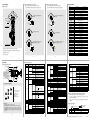
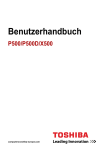
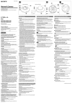
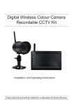
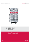
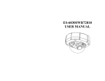
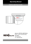
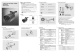
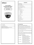
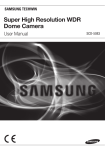
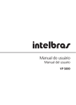
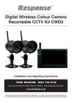
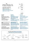
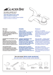
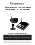
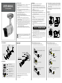
1. Warning & Caution
USER MANUAL
SK-P500(D)/M846AI
2. FEATURE
1) Please study the instruction manual before your applications and keep it
for your future reference.
2) Do not flash LED light directly on the eyes when LEDs are on.
3) Do not install the camera on a unstable surface. It will cause falling or other
hazards.
4) Do not use improper power, it could cause fire or electric shock.
5) Do not disassemble or remodel the camera, it could cause fire, electric
shock or other hazards.
6) Stop using the camera when you find a malfunction like smoke or unusual
heat, it could cause fire or electric shock.
7) Do not adhere dangerous aticles to the camera
8) Do not leave the unit along an unstable stand or table.
9) Power cable or Video cable should be always loose. Do not keep the cables
tight or twisted.
10) Use the camera unit within given temperature and electricity limit.
11) Use 24V AC or 12V DC, 1.5A regulated power supply.(Supply 24V AC to
dual voltage version only.)
12) Make sure that installation should be done by qualified service person only.
13) Do not disassemble the unit by yourself. When there is problem with the unit
please contact after-sale service center or the shop where you bought.
14) Stop operating and separate connector from the unit if below cases happen.
- When power connector or video connector is broken.
- When body is broken and dropped.
- When it is not operating though it is set correctly by the manual.
※If you meet any strange cases, please call the shop where you purchased.
If the product is to be put out of operation definitively, take it to a
local recycling plant for a disposal which is not harmful to the
environment.
6. WALL MOUNT
ON
OFF
45℃
40℃
17) D&N Mode, Mirror, BLC, HLC, DC Lens/Manual Lens, FLK, AGC, White
balance, Camera ID, Motion detection, LSC, Privacy, Gamma, Language
functions are controllable by OSD menu.
18) Horizontal Resolution 650 TV-Lines : Clear image quality has been
achieved by employing a 1/3" SONY Super HAD CCDⅡ with 410,000
pixels(NTSC), 470,000 pixels(PAL), which provides a horizontal resolution
of 650 TV-lines.
19) Privacy function(8 programmable zone) : The privacy zone function makes
it possible to mask specific areas of the scene from view.
20) Built-in Day&Night lens : This camera has a function that automatically
selects the mode that is appropriate for daytime or night-time conditions.
The COLOR mode operates in daytime conditions to provide optimum
colors, and BW mode operates in night-time conditions to enhance the
definition of the image.
21) Smart IR : When IR LED is turned on in B/W, the objects can be clearly
identified due to the function that decreases screen saturation of objects
within a short distance.
3. DIMENSION
Ceiling Mount
Ø106
79
158
172.3
180.1
Wall Mount
Ø106
79
158
172.3
266.8
4
6.2 How to install 2(Adjust horizontal angle)
6.3 How to install 3(Adjust vertical angle )
1) Loosen a bolt to adjust horizontal angle of the camera.
2) Use the WRENCH to tighten a bolt after adjusting the camera.
6.1 How to install 1
SUNVISOR
FIXING BOLT
Fan
3
2
4. CONFIGURATION
1) New generation, new technology GenⅤDSP adopted
2) Long visible range at night.(40m Max. indoors)
3) This camera adopts split glass technology to prevent IR light reflection.
4) This camera has vari-focal IR lens to prevent defocusing under IR lighting.
5) Adopted Smart DNR technology, It reduces noise efficiently in low light
condition.
6) DWDR(Digital Wide Dynamic Range)
7) IR cut filter is removed at night to receive maximum available light.
8) This product can match for any circumstances very well.
9) This product is suitable for 24 hours survillance with optical multi-coating
filter according to IR LED and CCD.
10) This product is weather-proof toresist rain, snow and other weather factors.
(IP65)
11) This product is made of corrosion-free surface to resist rust and corrosion
for a long time.
12) Sunvisor of this product can help the camera get the picture clearly.
13) Power & video cables are concealable(Cable through bracket).
14) This camera adopts 3-axis bracket to install on the ceiling and wall.
15) You can connect 24V AC or 12V DC regardless polarity.
(Dual power product only)
16) A fan enables the camera to keep the proper operation at high temperature.
(option)
- Fan ON/OFF temperature.(*ON/OFF point of fan is subject to environment)
1) Loosen a bolt to adjust vertical angle of the camera
2) Use the WRENCH to tighten a bolt after adjusting the camera.
POWER CABLE
12VDC
SUNVISOR
Twist a bolt counterclockwise once or twice.
Twist a bolt counterclockwise once or twice.
MOUNT HOLE PLATE
VIDEO CABLE
WALL
PROTECTIVE SHEET
(Remove it before
operating camera)
Ø86
WRENCH
ANCHOR 6X30 4EA
WRENCH
BRACKET
BODY
Ø30
SCREW TP1 4X35 4EA
Adjust vertical angle.
5. ACCESSORIES
Adjust horizontal angle.
ANCHOR 6x30 4EA
SCREW 4x35 Tp1 BIND SUS 4EA
Use the WRENCH to tighten a bolt after
adjusting the camera.
WRENCH TORX T10 1EA
Use the WRENCH to tighten a bolt after
adjusting the camera.
HEXAGON WRENCH 3.0mm
L TYPE 1EA
5
BOLT 1/4"-20UNC L=6, 1EA
1) Make a hole of Ø30mm in diameter for passing cable.
MOUNT HOLE PLATE
2) Using the mount hole plate, drill four holes on the wall.
3) Insert the anchors.
4) Fix the screws.
6
7
8
7. CEILING MOUNT
7.2 How to install 2(Adjust horizontal angle)
7.3 How to install 3(Adjust vertical angle)
1) Loosen a bolt to adjust horizontal angle of the camera.
2) Use the WRENCH to tighten a bolt after adjusting the camera.
7.1 How to install 1
1) Loosen a bolt to adjust vertical angle of the camera.
2) Use the WRENCH to tighten a bolt after adjusting the camera.
8. SPECIFICATION
Model No.
SK-P500/M846AI
1/3" SONY SUPER HAD CCDⅡ
Effective Pixel
768(H) x 494(V) Pixel(NTSC), 752(H) x 582(V) Pixel(PAL)
Cell Size
6.35㎛(H) x 7.4㎛(V)(NTSC), 6.5㎛(H) x 6.25㎛(V)(PAL)
2:1 Interlace
Scanning System
Ø86
Ø30
Ø6
Twist a bolt counterclockwise once
or twice.
Twist a bolt counterclockwise once
or twice.
Sync. Type
Internal
Resolution
650 TV-Line(COLOR), 720 TV-Line(B/W)
S/N
52dB or More(AGC OFF)
Video Output
MOUNT HOLE PLATE
1.0 Vp-p(Sync. Negative) Termination 75Ω
0.01 Lux(F/1.2), 0.0001Lux(Sense up)
0 Lux(40M Range) - Indoor
Min. Illumination
CEILING
γ= 0.45 typ.(0.2 ~ 1.0)
Gamma
WRENCH
Yes(Multi Language)
OSD
WRENCH
ATW(2,500°
K ~ 9,500°
K)/MANUAL/AWC
White Balance
ANCHOR 6X30 4EA
1/60(1/50) ~ 1/100,000sec
Shutter Speed
Auto(Selectable limit 2X ~ 1024X)/FIXED/OFF
Sense up
OFF/BLC/HLC/DWDR
Backlight
Adjust horizontal angle.
Adjust vertical angle.
SK-P500D/M846AI
Image Sensor
AGC
LOW/MIDDLE/HIGH/OFF
DNR(3D)
AUTO/LOW/MIDDLE/HIGH/OFF
Motion Detection
ON/OFF(4 Zone)
Privacy Zone
ON/OFF(8 Zone)
Mirror
ON/OFF
Day & Night
ICR/Electronic(AUTO, COLOR, B/W)
LED Brightness
Use the WRENCH to tighten a bolt
after adjusting the camera.
Use the WRENCH to tighten a bolt
after adjusting the camera.
30pcs, Smart IR
Blemish Compensation
AUTO/OFF
Communication(option)
RS-485(Protocol : Pelco D)
Lens
SCREW TP1 4X35 4EA
Day & Night Vari-focal auto iris lens
Power Supply
Regulated 12V DC ±10%
Current Consumption
Fan, Heater
1) Make a hole of Ø30mm in diameter for passing cable.
Option, Yes
Operation Temp.
2) Using the mount hole plate, drill four holes on the ceiling.
3) Insert the anchors.
4) Fix the screws.
-20℃ ~ 50℃
Preservation Temp.
-20℃ ~ 60℃
Dimension
79(W) x 80.5(H) x 172.3(D)mm
Weight
9
10
12V DC/24V AC Dual voltage
Max. 800mA(at 12V DC, 24V AC) : LED ON
Approx. 1.2kg
11
12
9.2 Camera menu setting
9. FUNCTION
9.1 Setup for camera functions
Function
setting menu
Extra video output
Right
Zoom
Focus & Zoom
fixing screw
Select menu
1. EXPOSURE
Down
BRIGHTNESS
MANUAL
LENS
Focal length adjustment direction
1. Unfasten the TORX screw inside
2. Adjust two knobs properly
3. Tighten the scew
<Caution> When you tighten the
screw, don't put stress
excessively
OFF, LOW, MIDDLE, HIGH
SENSE-UP
AUTO, OFF, X2, X4, X8, X16, X32,
X64,X128, X256, X512, X1024
BLC LEVEL
Left
BLC
1) Function setting combination
UP
BACKLIGHT
EXT. VIDEO
4
1
5
LEFT
SET
RIGHT
3
7
TOP
BOTTOM
LEFT
RIGHT
HBLC
6
2
E. SHUTTER
AGC
Set
Focus
Up
E. SHUTTER
BRIGHTNESS
DC
Debug port
Sub menu
SET : Displays the menu and
function selection
LEFT : Move to left
RIGHT : Move to right
UP : Move to up
DOWN : Move to down
HLC
MODE
HLC LEVEL
MASK 1~4
DOWN
SET LEVEL
D-WDR
OFF, LOW, MID, HIGH, AUTO
3D-DNR
RETURN
2. WHITE BALANCE
ATW
2 ) OSD menu
①SET : Press "SETUP" button to go to the menu.
②UP, ③DOWN : Use "UP" or "DOWN" button to go to the up or the down.
④LEFT, ⑤RIGHT : Use "RIGHT" or "LEFT" button to go to the right or the left.
⑥EXT. VIDEO : Extra video output terminal for installation. The cable is option.
⑦DEBUG PORT : It is used for upgrading the product function and after-sales
services.
13
MANUAL
M-WB
RETURN
PUSH
R-Y GAIN
B-Y GAIN
RETURN
0~99 : Adjust brightness with a manual iris lens
AUTO, 1/60, 1/100FLK, 1/120, 1/250, 1/500,
1/1000, 1/2000, 1/4000, 1/10000, 1/100000
: Adjust shutter speed
0~99 : Adjust brightness with a DC iris lens
AUTO, 1/60, 1/100FLK, 1/120, 1/250, 1/500,
1/1000, 1/2000, 1/4000, 1/10000, 1/100000
: Adjust shutter speed
Determines that use the AGC function or not
and AGC level selectable(You can not use the
Auto D&N change mode when AGC is off)
Using sense up when it is low luminance
(x2~x1024)
OFF, LOW, MID, HIGH : Use BLC function or not
/ level selectable
0~15: Adjust top position of BLC zone
1~16 : Adjust bottom position of BLC zone
0~15: Adjust left position of BLC zone
1~16 : Adjust right position of BLC zone
OFF : Deactivates HBLC function
MANUAL
HBLC LEVEL : OFF, LOW, MID, HIGH
TOP : 0~15
BOTTOM : 1~16 Make a zone for HBLC
LEFT : 0~15
RIGHT : 1~16
ALL DAY : Activates HBLC function all day
NIGHT : Use the function at night only
1~100 : Level adjust
ON
TOP : 0~33
BOTTOM : 1~34 Make a zone for HLC mask
LEFT : 0~44
RIGHT : 1~45
OFF : HLC MASK OFF
0~20 : DWDR level adjust
Reduce noise in low illumination(Level selectable)
Move back to previous menu
Color temperature 2500~9500
0~128 : Adjust the Red value to shift the color
of the object
0~128 : Adjust the Blue value to shift the color
of the object
Move back to previous menu
Find the optimal white balance for current
luminance environment
Adjust Red tone of the image
Adjust Blue tone of the image
Move back to previous menu
M-WR
AWB MODE
Contents
0~255
0~255
14
3. DAY&NIGHT
AUTO
D&N MODE
AUTO-CDS
COLOR
B&W
EXT
BURST
ON, OFF
C_SUP
0~100
A_SUP
0~100
ON, OFF
SMART IR
RETURN
4. IMAGE ADJUST
MIRROR
MIRROR, OFF
SHARPNESS
0~30
0.45, 0.55, 0.65
GAMMA
LSC
RETURN
5. MOTION
MOTION
AREA
SENSITIVITY
DISPLAY
HOLD TIME
ALARM OUTPUT
RETURN
6. PRIVACY
DAY→NIGHT
NIGHT→DAY
DELAY TIME
RETURN
A. DAY→NIGHT
A. NIGHT→DAY
C. DAY→NIGHT
C. NIGHT→DAY
DELAY TIME
RETURN
DELAY TIME
RETURN
USER
GAMMA
ON
RETURN
SET LEVEL
RETURN
OFF
ON, OFF
AREA 1~4
TOP
BOTTOM
LEFT
RIGHT
RETURN
RETURN
1~30
OFF, MESSAGE, TRACE
0~15
ON, OFF
Display each privacy mask or not
L_TOP, L_BOT, R_BOT, R_TOP : Determines which
of the 4 vertices of each MD area is to be used
ENTER SETTING : Determines the coordinate
ENTER SETTING : Move the mask
BLACK, WHITE, … : Select mask color(8 colors)
Move back to previous menu
Move back to previous menu
OFF
RETURN
ON
Set a vertical image inversion
Sharpness adjustable
Set a gamma value
0.20, 0.25, 0.30, 0.35, 0.40, 0.45, 0.50, 0.55,
0.60, 0.65, 0.70, 0.75, 0.80, 0.85, 0.90, 0.95,
1.00 : Gamma adjustable
Move back to previous menu
0~30 : Use the LSC and level adjustable
Move back to previous menu
LSC OFF
Move back to previous menu
Motion detection function activate/deactivate
0~143
2~145 Make a zone for motion detection
0~190
2~192
Move back to previous menu
Move back to previous menu
Motion detection sensitivity
Select notification method of motion detection
Set the duration of alarm out
Alarm ON/OFF
Move back to previous menu
DOT SEL
MASK 1~8
7~30 Select brightness of illumination about
6~29 changing the day↔night mode by AGC
0~15 : Select the duration time
Move back to previous menu
6~36 Select brightness of illumination about
6~36 changing the day↔night mode by AGC
0~255 Select brightness of illumination about
0~255 changing the day↔night mode by CDS
0~15 : Select the duration time
Move back to previous menu
Fixed at color
Fixed at B/W
0~15 : Change the color↔ B/W by external
signal(Not available)
Move back to previous menu
Transmit the burst signal or not in B/W mode
Color suppress controllable
Iris suppress controllable
Decreases screen saturation of objects within
a short range
Move back to previous menu
DOT XY
MOVE XY
COLOR
RETURN
15
7. SPECIAL
LANGUAGE
RETURN
ENGLISH, … : Select language(9 languages)
Display the camera name on the screen
Camera name reset
Camera name position
Move back to previous menu
1~255 : Select the camera ID for RS-485
communication
2400, 4800, 9600 : Select baud rate
PELCO-D : Camera protocol
Move back to previous menu
Deactivates Defect Pixel Correction in low
illumination
0~255 : Setup the limited value of white pixel
correction
0~255 : Setup the limited value of white pixel
correction
Move back to previous menu
Reset your camera to factory default condition
Return to previous menu
(Communication setting is not changed)
8. EXIT
SAVE AND EXIT
EXIT
RETURN
Save the value and exit menu
Escape the menu without save
Move back to previous menu
TITLE
OFF--ON
EDIT
RESET
POSITION
RETURN
ID
COMMUNICATION
OFF--ON
(option)
BAUDRATE
PROTOCOL
RETURN
OFF
AUTO
DPC
YES, NO
WHITE THR
LUMA THR
RETURN
FACTORY SET
9.3 How to control through RS-485 communication(option)
1) Match the camera with controller's ID, baudrate and protocol
2) Up, Down, Left and right of Jog lever is same as Up, Down, Left and
right of RS-485 controller
3) Enter of Jog lever is the same as menu key or IRIS open key of RS-485
controller
9.4 Cable array(option)
A : ORANGE(RX +)
B : WHITE(RX -)
No.
A
B
Function
RX +
RX -
Remark
RS-485A
RS-485B
16
※All specification is subject to change without notice to improve the quality.
3B15137B