1
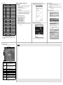
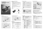
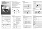
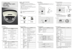
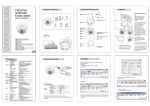
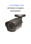
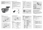
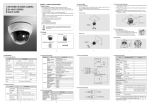
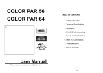
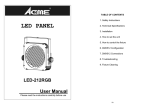
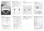
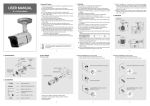
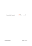
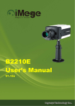
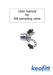
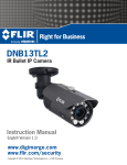
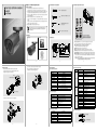
MEGA PIXEL NETWORK CAMERA
SK-NP611
Quick Guide
1.5 Camera setup(Control board)
1.3 Accessories for installation
Chapter 1. Install and Specification
1.1 Safety Cautions
1) This camera may be damaged by electrical and physical shock.
Use regulated 12V DC, 1A power supply. Do not throw or drop it onto floor.
2) This camera can be used outdoor. But if it is used outdoor, it is required to use
the sunvisor and avoid direct light from the sun. Do not use it under water.
3) In case it is installed at high location, be sure to mount securely to prevent the
unit from falling below.
4) In case the unit fails, DO NOT try to disassemble the product.
Contact or consult the distributor or an authorized technician for after-sales
service.
Warranty void for the product disassembled without an authorization from the
distributor or an authorized technician.
5) All responsibility by using this unit is on the user.
ANCHOR 6x30 4EA
SCREW 4x35 TP1 BIND SUS, 4EA
1
HEXAGON WRENCH 3.0mm
L TYPE, 1EA
3
If the product is to be put out of operation definitively, take it to a
local recycling plant for a disposal which is not harmful to the
environment.
4
BOLT 1/4"-20UNC L=6, 1EA
1.2 Package
7
Camera
Quick Guide
2
5
6
8
1.4 Dimension
Software & User Manual CD
131.3
236
241.1
86.4
*Focus/Zoom adjustment direction
1. Unfasten the screw of the bottom door
2. Adjust the Focus and Zoom trimmers
3. Tighten the screw of the bottom door
①FOCUS, ②ZOOM : Use a '+' type driver for adjusting focus and zoom.
(In case of operation Focus/Zoom, don't put stress excessively.)
③EXT. VIDEO : Extra video output terminal for installation.
Plug your test monitor in hear. The cable is option
④POWER : Light would turn on when power is on.
⑤Rx/Tx : Light would turn on when the user connect by the network.
⑥LINK : Light would turn on when the LAN cable is connected to the unit.
⑦SYSTEM RESET : Press the button to reset when the unit is not working normally.
⑧FACTORY RESET : Turn on the power and wait 2 minutes. Press the button
for 3 seconds to set the ID and Passwords for administration and IP setting
values to the Factory default.
[Reference] Please refer to Video Check in Chapter 2 and Chapter 5. System Setting
regarding default value.(Refer to the manual in the CD.)
2
1.6 How To Install
1. Make a hole of Ø25mm in diameter for passing cable.
2. Drill four holes on the wall or ceiling and insert the anchors.
3. Arrange the cables and fix the screws.
WALL
ANCHOR 6x30, 4EA
3
5. Loosen the bolt by using the 3mm wrench included.
6. Face the direction of the camera to monitor.
7. Tighten the bolt to complete adjustment.
BOLT
Ø6 Ø25
WRENCH
4
1.7 Specification
1.7.4 Network Specification
1.7.1 Camera Specification
Classification
Item
Specification
Model No.
Type
Image Sensor
Effective Pixels
Resolution
Scanning System
SK-NP611
Megapixel network Day&Night IR camera
1/3" SONY PROGRESSIVE SCAN CMOS(1.3 Mega Pixels)
1329(H) X 1049(V)
1280x1024 / 1280x960 / 1280x720 / 640x480 / 320x240
Progressive Scan
Alarm Input/Output
IR LED
Lens
Input : 1, Output : 1
70PCS
Vari-focal auto iris megapixel lens
1.7.2 Camera Function
Specification
Function
4. Attach the sunvisor and fix the sunvisor fixing bolt.
BOLT
SUNVISOR
Privacy Zone
Day&Night
WDR
ON / OFF(6 Programmable Zones)
Auto / Night / Day
WDR(1 ~ 5), (Back Light, Front Light)
Electronic Shutter
Auto : 1/15 ~ 1/9,000(NTSC), 1/12.5 ~ 1/8,000(PAL)
Suppress Rolling, Manual
Sense Up
White Balance
Auto(1 ~ 29)
Auto / Indoor / Outdoor / Fluorescent / User
1.7.3 Electric Specification
Classification
Power Supply
Current Consumption
Operation Temp.
Preservation Temp.
Dimension
Weight
5
6
Specification
Network Support
Leased Line, Cable Modem, Support Dynamic
IP and Static IP, ADSL usable under Router
Supported Protocol
TCP/IP, UDP/IP, RTP, RTSP, RTCP, NTP,
HTTP, DHCP, FTP, SMTP, DNS, DDNS
Security
PC OS
Web Browser
Compression
User authentication
WINDOWS XP, WINDOWS VISTA, WINDOWS 7
IE 7.0 or higher
H.264, MPEG-4, MJPEG
1280x1024 / 1280x960 / 1280x 720 /
640x480 / 320 x240
Compression Rate
200 : 1(Typical)
Frame Rate
Max. 30fps(@1280z1024)
Bit Rate
64 ~ 6000kbps
Simultaneous Access Max. 10 users
Recording in client PC with CMS or FTP Server
Video Recording
Motion Detection
Support
Privacy Zone
Support
OSD
Support
Alarm Input/Output
Support
Support
Dynamic IP
IP Router
Support
DDNS
Support
Resolution
Image
SCREW Tp1 4x35, 4EA
Specification
Embedded Linux
RJ45 10/100BaseT, Ethernet
By web browser
Summary
LED OFF : 0.01 Lux(Sense up Auto X4)
LED ON : 0 Lux(60M Range)
Min.Illumination
Item
OS
Network Interface
Setting
Function
1.7.5 Audio Input/Output
Regulated 12V DC, PoE(Power over Ethernet) - IEEE802.3af
MIC(Red)
Max. 1A(DC 12V) IR LED ON
-45℃ ~ 50℃
-20℃ ~ 60℃
86.4(W) x 101.9(H) x 131.3(D)mm
Approx. 1kg
LINE OUT(Black)
8
1.7.5 Basic Setting Table
Item
Chapter 2. Installation and Video Check
Default(Basic setting)
Remarks
On the assumption that User PC and the camera are used under static IP, and
the camera is to be directly connected with User PC or Local Network.
The installation procedure is to be;
1) Connect the camera and PC with LAN Cable.
2) Power on camera.
※Use regulated 12V DC, 1A
※Use PoE(Power Over Ethernet) : The cable includes data and power, so it's
easy to install the camera. So, you can save time to install and cost. When you
connect the camera with PoE and DC adaptor, Only PoE is used.
3) Wait about 2 minute after power on camera, the system will be booted.
Network
Static IP/Dynamic IP Static IP
IP Server Enable
Enable
IP Address
192.168.1.30
Gateway
192.168.1.1
Subnet Mask
Web Connection
Port
255.255.255.0
80
RTSP Port
554
RTP Port Range
5000 ~ 5999
2.1 Installation
Set IP Address, Subnet Mask and Gate-way of user's PC with 192.168.1.50 /
255.255.255.0 / 192.168.1.1 as shown on below picture.
2.2.3 Input ID/Password
Shown the main page, input ID and Password and click on "Viewer" to see the
video feed.(Default administrator's ID &Password is 'admin'.)
<Caution> Please change default value of ID/Password into new ones after the
installation.
[Reference] Please refer to 5.3 Administrator's ID and Password Change regarding
'Change Administrator'.
2.2.4 Active-X auto installation
Click "install" on the security certificate to load the Active-X control.
If you choose "Don't install", the web viewer would not work.
2.2 Network Setting and Video Check
Default network setting value of the unit is to be;.
ID and Password
Administrator
ID/Password
admin/admin
User ID/Password
root/root, guest/guest
①
IP Address : 192.168.1.30
Subnet Mask : 255.255.255.0
Gateway
: 192.168.1.1
2.2.2 Connect the camera with web browser
Domain of Related Server
To connect the unit in user's PC, change the setting value of PC network environment.
DDNS Server
<Caution> Before changing the setting value, please memorize the previous setting
value on your PC.
iplinker.net
Stream setting
H.264 15fps@ 1280x1024
rtsp://<ip address>:554/stream1
Stream 2
MJPEG 15fps@ 640x480
rtsp://<ip address>:554/stream2
Stream 3
None
rtsp://<ip address>:554/stream3
Video out*
OFF
After installation, deactivate it.
Stream 1
2.2.1 Change the setting value of PC network environment
Run web browser and input the default IP address(192.168.1.30) in URL line
and press "Enter". Then, below picture is to be shown.
②
③
Other Setting
Time Zone
Asia/Seoul(Korea)
[Reference] In case to reset hardware and network setting, ID and password of user
and Administrator will be automatically returned to the above default value.
*Frame rate can be affected by the external video output option.
So factory default is off. When you install the camera, enable this option. Then disable
it after the installation.
9
※If the page does not open, Please refer to "Chapter 11 appendix" in the CD.
10
11
12
2.2.5 Complete the installation
Upon installation, Web Viewer appears and image of camera is to be seen.
⑦
⑧
⑨
⑩
①
②
③
④
⑤
⑥
11
Item
Description
①Stream selection
Select stream codec and resolution menu related to
live-view was defined only by the admin.
(H.264/MPEG/MJPEG)
②Window size
Default size is 640X480.
Adjust the screen to the optimal size(Recommendation :
Select the same size with stream resolution)
③Connection/Disconnection
④Recording
⑤Capture
⑥Saving path
⑦Camera name
⑧Date
⑨Time
Connect or disconnect to the stream
Saves the stream as a moving picture file in the .avi format
Saves the snapshot as an image file in the .bmp format
Specify the file saving path
Display camera title
Display the date
Display current time
⑩Status Icon
Display the site information such as Day/Night, Motion,
Alarm input/output
⑪Stream Info.
Display the stream information such as Audio and
recording condition
13
※The specification is subject to change without any prior notice to improve the quality.
3B15963C