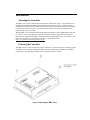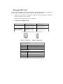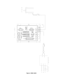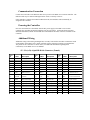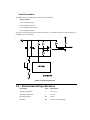
1
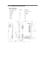
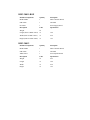
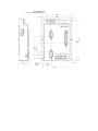
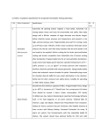
DMC-3xx1x Series Installation Manual-ETL
DMC-3xx1x Integrated
Amplifier Installation
Manual
Manual Rev. 1.0a2
By Galil Motion Control, Inc.
Galil Motion Control, Inc.
270 Technology Way
Rocklin, California 95765
Phone: (916) 626-0101
Fax: (916) 626-0102
E-mail Address: [email protected]
URL: www.galilmc.com
Rev 02/29/12
Using This Manual
This manual provides information for the wiring, installation, powering-up, and basic communication
to the DMC-3xx10, DMC-3xx11 and DMC-3xx12 series motion controllers. The following list of part
numbers are examples of configurations of the DMC-3xx1x motion controller that are covered in this
manual.
DMC-30010: 1-axis controller no power supply, no amplifier.
DMC-30011: 1-axis controller with 48VDC power supply, no amplifier.
DMC-30012: 1-axis controller with 60VDC power supply and sine amplifier
This manual covers the basic installation of the controller and amplifier modules. For full operational
information including specific I/O installation, detailed programming examples and additional internal
driver information, see the DMC-3xx1x User Manual.
WARNING: Machinery in motion can be dangerous! It is the responsibility of the user to
design effective error handling and safety protection as part of the machinery. Galil shall
not be liable or responsible for any incidental or consequential damages.
If the DMC-3xx1x motion controller and included amplifiers or stepper drivers are not used
in a manner specified by Galil Motion Control, the protection provided by the controller,
amplifiers and drivers may be impaired.
Chapter 1 Overview
Introduction
DMC-3xx1x Motion Controller
The DMC-3xx1x Series is Galil’s latest generation single-axis motion controller. It uses a 32-bit RISC
processor to provide higher speed than older models. The DMC-3xx1x is available as a compact cardlevel or box-level unit and connects to a stepper or servo motor amplifier of any power range. Or, the
DMC-3xx1x can be purchased with an internal 800-Watt brushless sine drive which minimizes space,
cost and wiring. The motion controller operates stand-alone or can be networked to a PC via Ethernet.
Features include PID compensation with velocity and acceleration feedforward, program memory with
multitasking for concurrent execution of multiple programs, and uncommitted optically isolated inputs
and outputs for synchronizing motion with external events. Modes of motion include point-to-point
positioning, jogging, contouring, PVT, electronic gearing and electronic cam. Like all Galil motion
controllers, these controllers use a simple, English-like command language which makes them very
easy to program. GalilTools software further simplifies system set-up with “one button” servo tuning
and real-time display of position and velocity information.
Commands are sent in ASCII. Additional software is available for automatic-tuning, trajectory
viewing on a PC screen, and program development using many environments such as Visual Basic, C,
C++ etc. Drivers for Windows XP, Vista and 7 (32 & 64 bit) as well as Linux are available.
DMC-3xx10
The DMC-3xx10 is a single-axis controller with no power supply and no amplifier.
DMC-3xx11
The DMC-3xx11 is a single-axis controller with a 48VDC power supply and no amplifier.
DMC-3xx12
The DMC-3xx12 is a single-axis controller with a 60VDC power supply and and a single axis
sinusoidal amplifier. The DMC-3xx12 is capable of 10 Amps of continuous current and 15 Amps of
peak current.
Chapter 2 Installation
Pre-Installation
Operating Environment
The location for use of the DMC-3xx1x must meet the following requirements.
Description
Units
Specification
Ambient Temperature
C
0 to +40
Altitude
feet
10,000
Humidity
RH
20-95% (non-condensing)
Mounting Location
The DMC-3xx1x motion controller must be mounted on a flat surface using the 4 mounting holes
found on the metal base-plate. The grating found on the side of the metal must not be obstructed in
order provide proper air flow for adequate heat dissipation. The dimensions and the mounting hole
locations are found in Appendices A3.
Additional Mounting Consideration when using the DMC-3xx12
When operating a DMC-3xx12, special mounting considerations must be made if the total continuous
current output for the controller is greater than 5A. In this case, the controller base must be mounted to
an addition heat sink.
When the application requires that the DMC-30012 be mounted to a heat sink, the heat sink must be
sized such that the base of the DMC-30012 be kept at a temperature of 65O C or below. This works out
to a thermal resistance of 2O C/W at full continuous power. Full continuous power is defined as a
100% duty cycle at 10Amps continuous current with a 60VDC bus.
Elements Needed for Installation
1.
Isolated DC power supply
a.
Ratings found in Appendix A1
2.
Power Supply Cable
3.
PC or laptop with Ethernet and/or RS-232 ports
4.
GalilTools, or GalilTools-Lite software package
5.
Ethernet Cable
a.
6.
Recommended shielded Cat 5 STP cable. Straight-through or Cross-over.
RS-232 straight-through serial cable
a.
9 pin D-sub female
7.
Molex pin Crimp Tool
8.
Additional cables may be required for connection to motors, external amplifiers, digital or
analog I/O, and other devices. See the full DMC-3xx1x User Manual for further information.
9.
Disconnect switch or circuit breaker for AC power to DC Power Supply
Unpacking the Controller
Caution:
1.
The DMC-3xx1x motion controller and included internal amplifier include electrostatic
sensitive components. Observe standard precautions for handling ESD sensitive devices
when handling the controller.
Verify that the following components have been shipped along the motion controller.
•
•
Note:
Connectors and mating pins for motor power and amplifier power.
o
Qty 1 – 4 pin molex connectors (DMC-3xx12)
o
Qty 1 – 2 pin molex connector (DMC-3xx11 and DMC-3xx12)
o
Qty 1 – 4 pin molex connector (DMC-3xx10)
Galil Software Installation CD
Connectors and/or software installation CD may not be shipped to existing OEM
customers.
2.
Check that no visible damage has occurred to the controller, or internal amplifiers. If any
damage has occurred to the controller, or the components shipped with the controller, contact
Galil Motion Control immediately. Contact information can be found in the beginning of this
manual.
3.
Verify the controller that has been shipped to you is in fact the controller that you have
ordered from Galil or your authorized Galil distributor. To do this, check the labeling on the
controller and compare it to the part number that was ordered.
Figure 1: Label for DMC-3xx10
Figure 2: Label for DMC-3xx11
Figure 3: Label for DMC-3xx12
Figure 4: ETL Mark
Installation
Mounting the Controller
The DMC-3xx1x motion controller must be mounted to a flat surface with 4 – #10 pan head screws
through each mounting hole found on the controller base as shown in Figure 5. If the controller is
mounted on a wall, the controller should be mounted so that the bottom of the controller is horizontal
to the floor (as shown in Figure 5). The enclosure must meet or exceed any fire ratings that are
required of the system as a whole.
With the DMC-3xx12 it should be determined at this time whether or not an additional heat sink will
be required. This is determined based upon the continuous current requirements of the system as
defined in the “Additional Mounting Consideration when using the DMC-3xx12” section above. The
Motor Sizer tool found on our website can be used to determine this value
http://www.galilmc.com/learning/motorsizer.php.
Powering the Controller
The DMC-3xx1x is powered via the DC supply connections. All connectors share a common ground.
The DMC-3xx1x is grounded through the metal enclosure and should be installed on an unpainted
metal surface. The Earth lugs should be used for additional electrical contact.
Figure 5: Mounting the DMC-3xx1x
Wiring the DMC-3xx12
The basic wiring for a DMC-3xx12 is shown in Figure 6. The disconnect switch or circuit breaker for
AC power must be installed in a location that meets the following requirements:
•
Placed in close proximity to the equipment, within easy reach of the operator, and must not
block the installation of the controller
•
Marked as the disconnect device for the equipment
Connectors for DMC-3xx12
POWER
A,B,C,D: 4-pin Motor
Power Connectors
On Board Connector
Terminal Pins
2-pin MATE-N-LOK
MOLEX# 39-31-0020
MOLEX#44476-3112
4-pin MATE-N-LOK
MOLEX# 39-31-0040
MOLEX#44476-3112
For mating connectors see http://www.molex.com/
Power Connector
Pin Number
Connection
1
DC Power Supply Ground
2
+VS (DC Power)
Motor Connector
1
Phase C
2
Phase B (N/C for Bushed Motors)
3
No Connect
4
Phase A
Figure 6: DMC-30012
Communication Connection
Connect the serial cable or the Ethernet cable from your PC to the DMC-3xx1x motion controller. The
Ethernet cable may be connected through a hub or switch, or directly to the PC.
If the controller is connected to a DHCP enabled network, the IP address will automatically be
assigned to the controller.
Powering the Controller
Once the connections have been made from the DC power supply to the DMC-3xx1x motion
controller, the controller and internal amplifiers may be powered-up. At this time the Power LED
should be illuminated, and the LCD should turn on and indicate the status of the axes available on the
controller.
Additional Wiring
Additional wiring to the Analog and Digital I/O, encoders, limit switches and other connections found
on the D-Subs on the DMC-3xx1x motion controller will be required to complete your applications.
The pinout for the connectors are shown below, for additional information regarding these
connections, see the DMC-3xx1x User Manual.
J5 - I/O (A-D) 44 pin HD D-Sub Connector (Female)
Pin
#
Label
Description
Pin
#
Label
Description
Pin
#
Label
Description
1
AI1
Analog Input 1
16
AGND
Analog Ground
31
AI2
Analog Input 2
2
AO2
Analog Output 2
17
AO1
Analog Output 1
32
-12V
-12V
3
N/C
No Connect
18
+12V
+12V
33
GND
Ground
4
ERR
Error Output
19
AEN
Amplifier Enable
34
CMP
Output Compare
5
MF1 -
Multi Function 1 -
20
GND
Ground
35
MF1 +
Multi Function 1 +
6
MF2 +
Multi Function 2 +
21
MF2 -
Multi Function 2 -
36
MF3 -
Multi Function 3 -
37
MF4 +
Multi Function 4+
38
FLS
Forward Limit Switch
Input Common
7
MF4 -
Multi Function 4 -
22
MF3 +
Multi Function 3
+
8
LSCOM
Limit Switch
Common
23
+5V
+5V
9
HOM
Home Switch Input
24
RLS
Reverse Limit
39
INCO
M
10
DI2
Digital Input 2
25
DI1
Digital Input 1
40
DI3
Digital Input 3
11
DI5
Digital Input 5
26
DI4
Digital Input 4
41
DI6
Digital Input 6
12
DI8
Digital Input 8
27
DI7
Digital Input 7
42
ELO
Electronic Lockout
13
RST
Reset Input
28
ABRT
Abort Input
43
OP0A
Output GND/PWR
14
DO2
Digital Output 2
29
DO1
Digital Output 1
44
DO3
Digital Output 3
15
OP0B
Output PWR/GND
30
DO4
Digital Output 4
J4 - Encoder 15 pin HD D-Sub Connector (Female)
Pin #
Label
Description
1
MI+
I+ Index Pulse Input
2
MB+
B+ Main Encoder Input
3
MA+
A+ Main Encoder Input
4
AB+
B+ Aux Encoder Input
5
GND
Digital Ground
6
MI-
I- Index Pulse Input
7
MB-
B- Main Encoder Input
8
MA-
A- Main Encoder Input
9
AA-
A- Aux Encoder Input
10
HALA
A Channel Hall Sensor
11
AA+
A+ Aux Encoder Input
12
AB-
B- Aux Encoder Input
13
HALB
B Channel Hall Sensor
14
HALC
C Channel Hall Sensor
15
+5V
+5V
Communication with Galil Software
To communicate with the controller, the GalilTools communications software must first be installed.
A free version of GalilTools (GalilTools-Lite) may also be used. These software applications can be
found on the software installation CD shipped with the controller, or online at:
http://www.galilmc.com/support/software-downloads.php
Installation instructions for your operating system can be found in the GalilTools user manual.
http://www.galilmc.com/support/manuals/galiltools/introduction.html
Once the software has been installed, run GalilTools, or GalilTools-Lite and choose your controller.
RS-232 connection
If you are using over a serial connection, the standard baud rate of the DMC-3xx1x motion controller
is 115200. For a standard serial connection over COM1, choose COM1 115200 in the connections
dialog window.
Ethernet connection
If you are connected to the controller via an Ethernet connection, and your network is DHCP enabled,
then the controller will automatically have an IP addressed assigned to it. If your network is not
DHCP enabled, or the connection is only between the PC and the controller, then the controller be
found with the software as no IP address assigned. The GalilTools software will allow you to assign
the controller with an IP address. See the GalilTools documentation for detailed information on using
the software to assign the controller IP address.
Appendix – Specifications
A1 – Electrical Specifications
DMC-30010
Description
Units
Specification
Input Voltage
VDC
5, +/-12
Maximum Input Power
W
3
Description
Units
Specification
Maximum Input Voltage
VDC
48
Minimum Input Voltage
VDC
9
Maximum Input Power
W
3
Description
Units
Specification
Maximum Input Voltage
VDC
60
Minimum Input Voltage
VDC
20
Maximum Input Power
W
300
Maximum Output Current
Amps
10
Peak Output Current
Amps
15
Amplifier Gain
A/V
0.4, 0.8 (default), 1.6
Switching Frequency
kHz
33
Supply Voltage Fuse
Amps
15
DMC-30011
DMC-30012
Fault Information
The DMC-30012 protected from the following fault conditions.
Fault Condition
Over-Current Protection
Under-Voltage Protection
Over-Temperature Protection
Over-Voltage Protection
The Over-Current protection circuit is shown in Figure 7. For further specifics on fault conditions, see
the DMC-3xx1x User Manual.
Figure 7: Overcurrent Circuit
A2 – Environmental Specifications
Description
Units
Specification
Storage Temperature
C
-40 to +125
Operating Temperature
C
0 to +40
Operating Altitude
feet
10,000
Humidity
RH
20-95% (non-condensing)
A3 – Mechanical Specifications
DMC-30010-BOX
Included Components
Quantiy
Description
MCB-300M0
1
Main Controller Board
IOB-300I0
1
I/O Board
Description
Units
Specification
Weight
lb
0.71
Length
in
3.88
Width
in
4.20
Height
in
1.36
DMC-30011-BOX
Included Components
Quantiy
Description
MCB-300M0
1
Main Controller Board
IOB-300I0
1
I/O Board
PS-300P1
1
Power Supply Board
Description
Units
Specification
Weight
lb
Length (Same as DMC-30012)
in
3.88
Width (Same as DMC-30012)
in
4.50
Height (Same as DMC-30012)
in
1.45
Included Components
Quantiy
Description
MCB-300M0
1
Main Controller Board
IOB-300I0
1
I/O Board
AMP-300A2
1
Sine Amplifier Board
Description
Units
Specification
Weight
lb
0.95
Length
in
3.88
Width
in
4.50
Height
in
1.45
DMC-30012