1
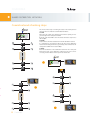
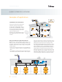
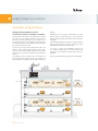
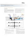
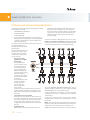
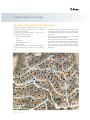
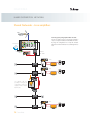
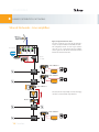
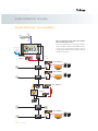
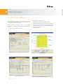
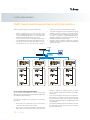
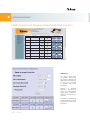
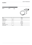
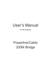
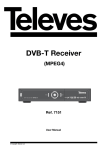
2012 COAXDATA COAXDATA CONTENTS 1. Ethernet coaxial adapter. 1.1 Coaxdata homeplug. 1.2 Physical description. 2. Home networking. 3. Home networking - Examples of application. 3.1 Home networking. 3.2 PLC option. 3.3 Hybrid option. 4. Shared distribution networks. 5. Coaxial network checking. 6. Coaxial network checking steps. 7. Shared distribution networks - Examples of applications. 7.1 Small/Medium shared distributions networks. 7.2 Using several master modem at the headend. 7.3 Making individual installations of home-networking in a number of dwellings of a building. 7.4 Establishing AVLNs. 8. Professional and special applications. 9. Shared distribution networks - line amplifiers. 10. System management. 11. Coaxmanager software. 12. Snmp (simple network management protocol) with web interface. 2 Coaxdata COAXDATA The bandwidth of the coaxial cable allows to multiplex a number of services other than televison. Coaxdata is a state-of-the-art system that converts a television coaxial network into a high speed local network. By means of Coaxdata, sharing resources (computers, printers, an internet connection, etc) does not need any additional cable. COAXDATA ETHERNET COAXIAL ADAPTER Coaxdata Homeplug The Coax Data 200 Mbps-HDTV adapter makes the transmission of data possible over the existing electrical and/or coaxial distribution. The use of the already existing coaxial network infrastructure allows for a rapid, easy and economic installation of the system, without the need for construction. ▶ Transfer of up to 200 Mbps, ideal for uses such as VoIP, telephony, Internet TV, VoD, shared access to Internet and IP data communications in general. ▶ Integrated quality of service (Quality of Service, QoS) for prioritisation of the data. All this guaranteeing ideal transmission and maximum safety by means of the 128bit AES coding. ▶ Flexible and upgradable solution for the construction of segments of up to 253 devices. In the MDU/MTU mode over coaxial alone, there is the possibility of using up to 4 Masters in the same frequency band (1012 slaves). ▶ No changes are necessary in the topology of the coaxial network to coexist with existing TV services. Coaxial cable high attenuations (~85dB) are supported. Coaxial cable lengths up to 800m are supported as well as power line lengths up to 200m . ▶ Remote management is possible by means of the Coax Reference Connectorization Ethernet interface Coaxial interface Data coaxial interface Bandwidth Output level Min. power spectral density Output impedance TV coaxial interface Bandwidth Through losses Return losses Output impedance Power/Temperature Mains voltage (50/60 Hz) Max. consumption Operating temperature Firmware Max. number of slaves Max. length data network of Coax cable Power line Users per slave Manager Software included in the CD and Control Access Software. ▶ This allows configuring the devices with the parameters that the installer may require: Operating mode [Home Networking or MDU (Multi Dwelling Unit) / MTU (Multi Tenant Units)] QoS parameters Access code to the network And many other possibilities of adjustment. ▶ User Manual is included in the CD which comes with the product. MDU/MTU 7689 type 2 × RJ45 2 × F(TV+data) MHz dBμV dBm/Hz ohm 2-30 130 -135 75 MHz dB dB ohm 57-2150 2 > 10 75 Vac W/mA ºC 100-240 4.6 / 45 -10 to +45 master 85 dB 85 dB 85 dB 85 dB slave slave slave m no. 253 (1012 using 4 masters) 800 200 2 85 dB 85 dB 85 dB 85 dB Multipoint-To-Multipoint 4 Coaxdata slave Point-To-Multipoint Home Networking with automatic configuration master/slave There is no conection between slaves 85 dB no. 7689 COAXDATA ETHERNET COAXIAL ADAPTER Physical description Coax / Hybrid Coaxial cable Electric cable Coaxial Link Status TV + data TV 120 Mbps < throughput 70 Mbps < throughput < 120 Mbps Ethernet 10/100 Mbps 0 Mbps < throughput < 70 Mbps factory reset Medium connectivity switch Coaxial & Electric cables Coaxial cable only Examples of application - Home Networking BASIC INSTALLATION Coaxial option. One of the most typical applications of the CoaxData-200Mbps-HDTV modem, is used to share the services of your Internet provider at home. Ref. 7654 Using the modem, you will get access to the services provided by your ISP such as the Internet access, video streaming or VoIP throughout the home without requiring additional infrastructure. The following diagram shows a prototype facility in which a user can access the different services provided by the Internet, anywhere in the house. You can also share printers and media servers located in other rooms of the same. 5 Coaxdata the Internet Share printer, NAS Media Server, the Internet, ... on the same network COAXDATA HOME NETWORKING Examples of application - PLC option BASIC INSTALLATION The Coax Data 200Mbps-HDTV adapter is factory configured to be able to perform a Home Networking plugand-play installation. This allows for the creation of an LAN, where all the devices communicate with each other (peer-topeer). MAINS In this application it is used the electric network infrastructure of the house for data trnasmission (PLC). The main benefit of this application is based on the fact that the electrical network reaches every corner of the home. the Internet Examples of application - Hybrid option BASIC INSTALLATION The Coax Data 200Mbps-HDTV adapter is factory configured to be able to perform a Home Networking plugand-play installation. This allows for the creation of an LAN, where all the devices communicate with each other (peer-topeer). MAINS In this application it is used both coaxial cable and electric infrastructures of the house for data trnasmission (COAX + PLC). the Internet In other words, whichever electric or coaxial outlet can be a LAN point. 6 Coaxdata COAXDATA SHARED DISTRIBUTION NETWORKS Coaxial network checking Before to enface any shared distribution network to be equipped with the capability for distributing data using the modem ref. 7689, it is nesessary to know if that particular network has its return path in conditions to distribute data. Some test equipment is necessary to carry out this job: • Field Strength Meter, with good specifications as to measure the noise in the return path like our H45. • Return path simulator ref. 7637 • Diplexer filters ref. 7654. Our Field Strength Meter H45 meets all the requirements to do this job. H45 Simulador canal de retorno 0 1 7 6 2 3 5 4 7637 The first step is check the output of the Return Path Simulator with the H45 Meter and record it a a reference for further measures. Simulador canal de retorno 0 1 7 6 7 Coaxdata 2 3 5 4 Set operating mode to 7 7654 COAXDATA SHARED DISTRIBUTION NETWORKS Coaxial network checking steps PWR CTRL Ref. 7654 Ref. 7654 The aim of all these steps is checking the status of the return path and determine if it is in conditions to transmit data information. 1st STEP Disconnect the output of the Headend and check the quantity of noise generated by it in the return path 5-30 MHz By means of the meter H45 it can be measured and must be equal or less than 50 dBμV. 2nd STEP Next, make the same measure but this time for the distribution network. It is performed by connecting the H45 to the input of the distribution network and checking that the noise generated by all its elements into the return path 5-30 MHz never exceeds 25 dBμV. 3rd STEP Check the attenuation of the distribution network for the return path between the input of the distribution network and the worst case for conecting a modem 7689. It must be equal or less than 80 dB. PWR CTRL Ref. 7654 Ref. 7654 Simulador canal de retorno 0 1 7 6 2 3 5 4 Ref. 7654 Ref. 7654 Ref. 7654 is Ref. 7654 Ref. 7654 on Ref. 7654 Ref. 7654 Ref. 7654 8 Coaxdata COAXDATA SHARED DISTRIBUTION NETWORKS Examples of applications master slave Small/Medium shared distributions slave slave slave master These type of networks used to work having a master to control the rest of modems. The Coax Data 200Mbps-HDTV adapter is an ideal device for Networking country Houses and small Hotels, where a master is controlling the streaming of information between the different slaves. slave This way it can be enabled/disabled any of the CoaxData adapters by using a software of control. slave Using several master modem at the headend When there are several downlead coaxial sections, as it happens in most of the large multi-dwellings buildings, you can install several masters at the headend of the coaxial distribution network. Each master serving an independent coaxial downlead. • In this case, we must note that there are several differences with respect to facilities in which are established several AVLN. • The installation of several masters at the headend increases the effective data-rate that the network is able to support, slave slave where each data network is created in a independent coaxial distribution, which increases the total system capacity by facilitating the development of video streaming or IPTV. • The master modems installed at the headend do not have to be configured with different network password since they operate separately on each coaxial distribution networks. • To increase the isolation between these master modems, use the filter diplexer ref. 7654 for mixing TV signals and data. • In this type of schemes is also necessary to take into account the losses suffered by the TV signal in the process for multiplexing TV+Data signals; this is so because of the need to chose the right type of taps for the distribution network. Internet Ref. 7654 9 Coaxdata Ref. 7654 Ref. 7654 Ref. 7654 COAXDATA SHARED DISTRIBUTION NETWORKS Examples of applications Making individual installations of homenetworking in a number of dwellings of a building. Even though the outlets shall be properly isolated to prevent that each one of the dwellings interfere with each other in TV services and data, depending on the conditions of its installation, they may not be adequately isolated; and then the data networks installed at the dwellings of the building will get interferences with each other. In this case, you must install a diplexer filter 7654 at the entrance of each dwelling coaxial network in order to avoid that each of the nearby networks interfere with each other, and that the noise of the head interferes with the quality of the links. The installation of these diplexers allow to determine the perimeter in which the master serves a data network and allows installation of multiple networks within a building or dwelling. Additionally, if it is not possible to install the filter, or suspect that your system is being affected by a close network and interfering with the quality of links, firmware 7689 provides a mechanism called additional mitigation that detects nearby networks and adjusts its transmit power and receiver sensitivity to reduce the effect that networks have with each other. To do this, by running the CoaxManager program, you can configure coaxData devices to detect nearby devices belonging to another different network, what is known as mitigation. Of course, the CoaxManager program must be enabled (☑) Network 1 diplexer ref. 7654 master tap slave slave slave slave ref. 7654 tap Network 2 master diplexer ref. 7654 slave ref. 7654 tap 10 Coaxdata slave slave slave COAXDATA SHARED DISTRIBUTION NETWORKS Examples of applications Establishing AVLNs by setting MDU/MTU as the operating mode of the modem. The ref. 7689 allows the installation of up four masters at the headend, which increases the potential number of modems that can be installed, but at the expense of total bandwidth to share. Each of the networks created by a master is called AVLN (AV logical network) and is established using different Network Passwords. The password must be different in each of the masters, and each slave must be programmed with the master password with which the slave wants to communicate. This password is set by means of the CoaxManager program, There is a limit to the maximum number of modems that can manage an AVLN (1 Master + 253 Slaves). By using 4 master modems, it can be increased the limit of slave modems up to 4x253 = 1012 slaves. Masters AVLN _I AVLN _II AVLN _III AVLN _IV master slave router slave slave slave Internet Headend diplexer ref. 7654 Ref. 7654 TV switch with port isolation data CoaxManager program Control Access 4 way splitter tap Slave AVLN _III Slave AVLN _I tap Slave AVLN _IV Slave AVLN _II Up to 1012 slaves working on the same coaxial distribution network. When carrying out the installation of multiple masters consider the following: • Always use the diplexer ref. 7654 for TV and data signals, in order to ensure that the noise introduced by the headend in the return channel does not affect the quality of links. • Do not forget to schedule different passwords on each of the masters to create different AVLNs. • Do not forget to program the password of each one of 11 Coaxdata the slaves with the corresponding one to each of the masters. If the slaves are not programmed with the appropriate password, they will not able to communicate with any master. • You can check the status of each of the networks by running the CoaxManager program. To do this, you have to communicate with each one of the masters modem and verify the attenuation and the payload by simply connecting a laptop to the switch and running the program CoaxManager on each of the masters modem. COAXDATA SHARED DISTRIBUTION NETWORKS Professional and special applications Systems like these will need a support engineering for the design and installation, for example: • MATV/SMATV large distributions • small/medium CATVs • small/medium HFCs • and, in general terms, distributions over coaxial cable in buildings, medium and large hotels, housing management companies, residential homes, schools, hospitals, cruise ships, safety technology. The system uses the return channel coaxial passive network, and a determining factor is a maximum attenuation of 85 dB between points. headend elements with high output signal levels, such as channel processors, modulators, etc .... The existence of these elements would cause that, if they are poorly filtered, can add noise in the return channel of the network, thus affecting the master modem operation and leading to lower links quality. A professional network is differentiated by the need to use the management application/CoaxManager control included with the product. This software must be installed to adjust the product to certain characteristics that are out of the factory settings. For setting up these professional systems it is necessary to keep in mind a number of common characteristis to guarantee the success of the job. • • • The presence of line amplifiers to re-amplify the TV signal The data transmission system on which is based the ref. 7689 technology works in the frequency range 2-30 MHz, and is a bidirectional system since it generates signals coming either from the slaves connected to the outlets or from the master located at the headend. This implies that the return channel line amplifiers should be passive in order to ensure the bidirectionality of the return channel. It will be exposed an installation scheme on which are used two modems (ref. 7689) in a configuration called “Repeater” which allows propagate and regenerate the data signal. Large number of users and outlets The existence of a large number of outlets generates an increasing of the interfering noise in the return channel. This noise may appear in the outlets to a lesser degree, and decisively at the headend, because, being a tree configuration, the headend will add noise in each of the branches. Headend elements CATV networks are characterized by the existence of 12 Coaxdata The mode MDU/MTU (Multi-Dwelling/Multi-Tenant Unit) for complex installations, allows the use of the adapter 200 Mbps Coax-Data-HDTV in any coaxial network topology. This mode implements communication over a coaxial network in buildings, houses, hotels ..., establishing point to multipoint communication. To make these complex systems to work, the device must be configured either as master or as slave. Both functions can play the ref. 7689. Master is the element that is usually installed in the distribution headend to manage all network elements. Can be connected to an ISP (Internet Service Provider) to provide Internet access. A Slave is the element that provides the access point to the user. COAXDATA SHARED DISTRIBUTION NETWORKS Example of a professional application The figure below illustrates a typical distribution of a complex consisting of bungalows spreaded over an area of 375×375 square metres approximately. The challenge is just to desing a network in such a way that the maximum attenuation in the worst case never will be higher than 85 dB between the master and any of the slaves all along the network. This represents a professional solution to deliver at eact bungalow a complete menu of services: • TV broadcast (QAM, COFDM) • IPTV • the Internet • Video-On-Demand (VoD) • Triple Play (VoIP) Data transmission is performed making use of the PASSIVE return path of the network (2-30 MHz). This case study considers a network of 130 bungalows. That is, 130 units of the reference 7689 working as slaves of the master unit located in the headend. The master unit can handle up to 253 slave units, so the system could be significantly larger, always subject to the condition of 85 dB of maximum attenuation. The router is located at the Headend, where a master modem ref. 7689 controls the rest of modems that are operating as slaves. 12 4 124 A1 HEADEND T1 T1 12 25 25 T4 123 23 126 12 126 13 130 30 T10 T5 T9 12 29 29 127 12 27 2 128 12 1 2 122 122 22 T2 T3 T8 T7 104 10 104 04 121 121 12 116 T6 115 1 11 15 120 120 12 1 7 11 117 118 11 18 8 105 119 1 119 114 1 11 14 T18 106 06 113 3 112 2 10 1 107 0 07 75 75 T11 T12 10 3 10 103 111 1 108 108 8 74 74 T17 1 110 S1 10 09 9 83 83 73 3 102 10 1 02 84 T16 Sv2 85 5 8 81 T15 80 80 10 101 01 79 T47 72 2 100 1 00 82 T43 95 86 78 7 8 99 99 T42 66 T14 77 7 T13 T23 96 9 6 94 87 7 65 6 5 62 2 63 3 64 T45 67 7 97 97 98 98 T19 A5 76 6 T27 68 S5 A3 A2 88 88 93 9 3 T20 T38 61 61 T26 69 69 T21 T22 T24 70 T46 42 T28 92 92 89 89 T25 4 41 40 40 T39 71 71 60 60 S3 90 91 T40 59 5 9 34 4 T41 35 T29 33 3 3 36 52 58 8 37 7 38 38 39 3 9 53 3 51 1 32 2 57 7 31 4 43 30 0 24 24 56 6 29 29 22 22 21 21 T30 27 7 25 T37 26 6 S4 T31 49 9 45 5 A4 46 T33 T36 12 2 17 7 18 13 13 T35 15 5 14 T48 8 5 11 10 0 48 8 47 7 T34 16 16 19 19 9 7 1 6 3 4 13 Coaxdata 50 5 0 44 4 2 28 20 0 T32 54 55 55 23 23 2 COAXDATA SHARED DISTRIBUTION NETWORKS Shared Networks - Line amplifiers In the likely event that there are line amplifiers for signal reamplification on networks, caused by losses of coaxial cable and distribution components, it is necessary to ensure the coexistence of the data network with these amplifiers. Many times, line amplifiers tend to be unidirectional, ie only amplify the TV signal from the headend to the outlet of the user (forward channel). PWR The Internet CTRL This fact prevents data communications, since this is a bidirectional system, and we need a communication between the headend and the outlet, and vice versa. Diplexer TV - DATA Master To overcome this problem, the are several proposals that will be exposed in next paragraphs and illustrations. Let us review all possible situations as well as the procedure to solve them. Slave Ref. 7654 Slave Ref. 7654 Passive return channel inside the amplifier. The first task will be always make tests to be sure that the network is ready to accept the installation of CoaxData modems; as it has been explained previously, making use of a professional Field Strength Meter like our H45, diplexers, Return Channel Simulator device and the corresponding CoaxManager software. Line amplifier with the possibility of changing its configuration; ready to be equipped with a Return Path module. If the amplifier is featured with the possibility of inserting a Passive Return Path Module, there is no nothing more to do. The system will function for both forward path and return path. Ref. 7654 Slave Ref. 7654 14 Coaxdata COAXDATA SHARED DISTRIBUTION NETWORKS Shared Networks - Line amplifiers Passive bypass by using diplexer filter ref. 7654. First of all, make tests to be sure that the network is ready to accept the installation of CoaxData modems. By using this configuration it is kept the structure Master-Slave and the Remote Access Management as well. PWR The Internet CTRL Diplexer TV - DATA Master Slave Ref. 7654 Slave Ref. 7654 Line amplifier with the possibility of changing its configuration; ready to be equipped with a Return Path module. Ref. 7654 Slave Ref. 7654 15 Coaxdata COAXDATA SHARED DISTRIBUTION NETWORKS Shared Networks - Line amplifiers Bypass using the modem ref. 7689 First of all, make tests to be sure that the network is ready to accept the installation of CoaxData modems. The Internet This configuration allows to reach longer distances since the use of a new master after the amplifier, extends again those 85 dB extra attenuation allowed between the master and the slave. PWR CTRL Diplexer TV - DATA Master 1 Slave of Master 1 Ref. 7654 Slave of Master 1 Ref. 7654 Slave of Master 1 The tradeoff is the impossibility of remote managing since there is a intermediate step to Ethernet. Master 2 Ref. 7654 Slave of Master 2 Ref. 7654 16 Coaxdata COAXDATA SHARED DISTRIBUTION NETWORKS Shared Networks - Line amplifiers Bypass by using the modem 7689 and the diplexer filter ref. 7654.- High isolation. First of all, make tests to be sure that the network is ready to accept the installation of CoaxData modems. PWR The Internet In this case it might happen that there were not enough isolation. Then it could be used the solutions already seen for cascade. CTRL Diplexer TV - DATA Master 1 Slave of Master 1 Ref. 7654 Slave of Master 1 Ref. 7654 Slave of Master 1 Master 2 Ref. 7654 Slave of Master 2 Ref. 7654 17 Coaxdata COAXDATA SYSTEM MANAGEMENT CoaxManager Software This CoaxManager Software tool allows setting the operating mode and system parametres, as well as check either the network status or links of each device. Ad-hoc software development option i.e, management. Networking or MDU/MTU (Multi Dwelling Unit/Multi-TenantUnit). ▶ Create private networks (encryption). Scaning & configuration window ▶ ▶ ▶ ▶ QoS parametres configuration. ▶ Firmware updating. MACs (Media Access Control) limitation per Slave. IGMP (Internet Group Management Protocol) configuration. Detailed status link information, i.e SNR attenuation and tonemap list; allowing to get an itemized view of the installation performance. line quality window network checking window advanced users QoS window 18 Coaxdata COAXDATA SYSTEM MANAGEMENT SNMP (Simple Network Management Protocol) with Web interface well as the access to the current state of the network. Allows the remote magement of professional networks: ▶ Allows to configure the access mode of the coaxial modems CoaxData 200 Mbps, in such a way that a device can be enabled/disabled, set the access parameters like bandwidth and the number of user per modem. ▶ Lets you check the status of a network by determining the rate estimated between the links of the different devices. ▶ It allows the generation of alarms that alert the user of any incident like the loss of a device link, its poor quality, as ▶ The system configuration can be accomplished using the SNMP protocol itself or through a simple Web interface for users without technical knowledge of this protocol. To do this it is provided a complete MIB (Management Information Database) specification that defines all the SNMP objects implemented by the agent. ▶ Automatic sending of emails for tracking the system and notifying incidents coming from either the management system or the devices. Internet modem is configured as networking mode, the system sends an alarm to indicate that the modem is operating in a wrong way. Access control setting-up requirements For the installation of the SNMP access control is necessary a PC with a Windows operating system NT/2000/XP/Vista/Windows7 and an Ethernet Network Interface. ▶ In the event that multiple masters have been installed on the network, do not forget to ensure that the insulation between them in the return channel is greater than 80dB. If necessary, use the filters diplexers Ref.7654 between each coaxial networks. ▶ In the event that multiple masters are installed, be sure that the Switch that interconnects them must have activated the port isolation feature. The scheme of installation of the application is shown in the figure above. ▶ The PC where it is installed the access control must be connected to the master (s) of the network. ▶ The mode of operation of all installation modems will be MDU / MTU. If it is installed the access control and some 19 Coaxdata COAXDATA SYSTEM MANAGEMENT SNMP (Simple Network Management Protocol) with Web interface Description MAC Address Master I 00:0E:7C:15:01:CE Link State Access State Enable Change configure access Configure access Master II 00:0E:7C:15:02:00 Enable Change configure access ROOM 101 00:0E:7C:15:01:ED Enable Change configure access ROOM 102 00:0E:7C:15:01:3C Enable Change configure access ROOM 103 00:0E:7C:15:02:66 Enable Change configure access ROOM 104 00:0E:7C:15:02:07 Enable Change configure access ROOM 105 00:0E:7C:15:02:4A Enable Change configure access ROOM 106 00:B0:52:00:00:17 Enable Change configure access SNMP Agent The devices menu shows all modems detected by the system, indicating their MAC address and link state, as well as the possibility to configure their access parametres. Enabling or disabling modems ir performed by using the Enable/Disable option. When a modem is disabled, it is indicaetd by a red circle. To Eliminate a modem from the list just make use of the option Delete on the Access Control List 20 Coaxdata COAXDATA SYSTEM MANAGEMENT SNMP (Simple Network Management Protocol) with Web interface This interface allows configuring the generation of traps to receive mails in a specific mail address. It also allows activating/deactivating the alarms of the system. 21 Coaxdata COAXDATA 2012 COAXDATA Sede Central Rúa B. de Conxo, 17 15706 Santiago de Compostela (SPAIN) T. 902 686 400 F. 981 52 22 62 [email protected] - www.televes.com 22 Coaxdata