1
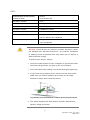
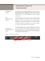
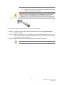
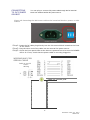
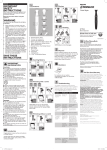
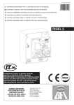
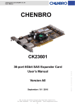
INSTALLATION and GETTING STARTE GUIDE GEFXL2-SW24K GbE Fiber Managed Switch Installation and Getting Started Guide i Publication date: Oct., 2013 Revision A1 INSTALLATION and GETTING STARTE GUIDE GEFXL2-SW24K Gigabit Managed Switch Installation and Getting Started Guide © 2013, Manufacture Corporation. All rights reserved. All brand and product names are trademarks or registered trademarks of their respective companies i Publication date: Oct., 2013 Revision A1 ABOUT THIS GUIDE PURPOSE This guide gives specific information on how to operate and use the management functions of the switch. AUDIENCE The guide is intended for use by network administrators who are responsible for operating and maintaining network equipment; consequently, it assumes a basic working knowledge of general switch functions, the Internet Protocol (IP), and Simple Network Management Protocol (SNMP). CONVENTIONS The following conventions are used throughout this guide to show information: WARRANTY See the Customer Support/ Warranty booklet included with the product. A copy of the specific warranty terms applicable to your Manufacture products and replacement parts can be obtained from your Manufacture Sales and Service Office pr authorized dealer. NOTE: Emphasizes important information or calls your attention to related features or instructions. WARNING: Alerts you to a potential hazard that could cause personal injury. CAUTION: Alerts you to a potential hazard that could cause loss of data, or damage the system or equipment. ii Publication date: Oct., 2013 Revision A1 COMPLIANCES AND SAFETY STATEMENTS FCC-CLASS A This equipment has been tested and found to comply with the limits for a Class A computing device pursuant to Subpart J of part 15 of FCC Rules, which are designed to provide reasonable protection against such interference when operated in a commercial environment. This equipment generates, uses, and can radiate radio frequency energy and, if not installed and used in accordance with the instruction manual, may cause harmful interference to radio communications. Operation of this equipment in a residential area is likely to cause harmful interference in which case the user will be required to correct the interference at his own expense. You are cautioned that changes or modifications not expressly approved by the party responsible for compliance could void your authority to operate the equipment. You may use unshielded twisted-pair (UTP) for RJ-45 connections - Category 3 or better for 10 Mbps connections, Category 5 or better for 100 Mbps connections, Category 5, 5e, or 6 for 1000 Mbps connections. For fiber optic connections, you may use 50/125 or 62.5/125 micron multimode fiber or 9/125 micron single-mode fiber. CE MARK This equipment has been tested and found to comply with the DECLARATION protection OF CONFORMANCE EN55022/EN61000-3 and the Generic European Immunity FOR EMI AND Standard EN55024. requirements of European Emission Standard SAFETY (EEC) iii Publication date: Oct., 2013 Revision A1 EMC: EN55022(2006)+A1:2007/CISPR Class A 22:2006+A1:2006 4K V CD, 8KV, AD IEC61000-4-2 (2001) 3V/m IEC61000-4-3( 2002) 1KV – (power line), 0.5KV – (signal line) IEC61000-4-4(2004) Line to Line: 1KV, Line to Earth: 2KV IEC61000-4-5 (2001) 130dBuV(3V) Level 2 IEC61000-4-6 (2003) 1A/m IEC61000-4-8 (2001) Voltage dips: >95%, 0.5period, 30%, 25periods IEC61000-4-11(2001) Voltage interruptions: >95%, 250periods CAUTION: Circuit devices are sensitive to static electricity, which can damage their delicate electronics. Dry weather conditions or walking across a carpeted floor may cause you to acquire a static electrical charge. To protect your device, always: • Touch the metal chassis of your computer to ground the static electrical charge before you pick up the circuit device. • Pick up the device by holding it on the left and right edges only. • If you need using outdoor device connect to this device with cable then you need to addition an arrester on the cable between outdoor device and this device. Fig. Addition an arrester between outdoor device and this switch • The switch supports the SFP Vendor includes: Manufacture, Agilent, Avago and Finisa iv Publication date: Oct., 2013 Revision A1 NOTE: The switch is indoor device; if it will be used in outdoor environment or connects with some outdoor device, then it must use a lightning arrester to protect the switch WARNING: z z z z z z RELATED PUBLICATIONS Self-demolition on Product is strictly prohibited. Damage caused by self-demolition will be charged for repairing fees. Do not place product at outdoor or sandstorm. Before installation, please make sure input power supply and product specifications are compatible to each other. To reduce the risk of electric shock. Disconnect all AC or DC power cord and RPS cables to completely remove power from the unit. Before importing / exporting configuration please make sure the firmware version is always the same. After firmware upgrade, the switch will remove the configuration automatically to latest firmware version. The following publication gives specific information on how to operate and use the management functions of the switch: The User’s Manual This section summarizes the changes in each revision of this guide. REVISION HISTORY Release 2.37 Date 2013/10/07 v Revision A1 Publication date: OCT., 2013 Revision A1 Contents ABOUT THIS GUIDE ................................................................................................. ii COMPLIANCES AND SAFETY STATEMENTS ....................................................... iii INTRODUCTION ........................................................................................................ 1 OVERVIEW............................................................................................................. 1 DESCRIPTION OF HARDWARE ............................................................................... 3 INSTALLING THE SWITCH ....................................................................................... 6 SELECTING A SITE ............................................................................................... 6 ETHERNET CABLING ........................................................................................... 6 EQUIPMENT CHECKLIST ..................................................................................... 7 PACKAGE CONTENTS ......................................................................................... 7 MOUNTING ............................................................................................................ 7 INSTALLING AN OPTIONAL SFP TRANSCEIVER .............................................. 9 CONNECTING TO AC POWER SOURCE ............................................................ 11 CONNECTING TO DC POWER SOURCE ........................................................... 12 FIBER OPTIC SFP DEVICES............................................................................... 13 SPECIFICATIONS ................................................................................................... 16 SWITCH FEATURES............................................................................................ 16 Store-and-forward ............................................................................................... 16 130.9 Mpps........................................................................................................... 16 MANAGEMENT FEATURES................................................................................ 17 STANDARDS ....................................................................................................... 17 COMPLIANCES ................................................................................................... 17 vi Publication date: Oct., 2013 Revision A1 INTRODUCTION OVERVIEW The GEFXL2-SW24K 24-Ports GbE Fiber Switch, Manufacture network next generation solutions, is a portfolio of affordable managed switches that provides a reliable infrastructure for your business network. These switches deliver more intelligent features you need to improve the availability of your critical business applications, protect your sensitive information, and optimize your network bandwidth to deliver information and applications more effectively. Easy to set up and use, it provides the ideal combination of affordability and capabilities for entry level Networking includes Small Business or enterprise application and helps you create a more efficient, better-connected workforce. The GEFXL2-SW24K 24-Ports GbE Fiber Switch is broad portfolio of easy-implement managed Ethernet switches. Models include with 24 ports of 1GbE Ethernet connectivity, providing ideal flexibility to design suitable network infrastructure for business requirement. However, unlike other entry-level switching solutions that provide advance managed network capabilities only in the costliest models, all the Series Switches support the advanced security management capabilities and network features to support includes data, voice, security, and wireless technologies. Besides, these switches are easy to deploy and configure, providing stable and quality performance network services your business needs. 1 Publication date: Oct., 2013 Revision A1 Front of the Switches AC 100V~240V Port 1-20 GbE SFP Port 21-24 GbE RJ45/SFP Power Input Fiber Connectors Fiber Connectors (Combo) Console (DB9) 48VDC Power Input SWITCH ARCHITECTURE The switch performs a wire-speed, non-blocking switching fabric. This allows wire-speed transport of multiple packets at low latency on all ports simultaneously. The switch also features full-duplex capability on all ports, which effectively doubles the bandwidth of each connection. This switch uses store-and-forward technology to ensure maximum data integrity. With this technology, the entire packet must be received into a buffer and checked for validity before being forwarded. This prevents errors from being propagated throughout the network. NETWORK MANAGEMENT OPTIONS The switch can also be managed over the network with a web browser or Telnet application. The switch includes a built-in network management agent that allows it to be managed in-band using SNMP or RMON (Groups 1, 2, 3, 9) protocols. NOTE: For a detailed description of the management features, refer to the User’s manual. 2 Publication date: Oct., 2013 Revision A1 DESCRIPTION OF HARDWARE The switch contains 10/100/1000BASE-T RJ-45 ports. All RJ-45 1000BASE-T PORTS ports support automatic MDI/MDI-X operation, auto-negotiation and IEEE 802.3x auto-negotiation of flow control, so the optimum data rate and transmission can be selected automatically. SFP TRANSCEIVER SLOTS GEFXL2-SW24K supports the Small Form Factor Pluggable (SFP) transceiver slots port 1 to port 24, the port 21 to port 24 are shared with RJ-45 (the port 21-24 are combo interface RJ45/SFP). In the default configuration, if an SFP transceiver (purchased separately) is installed in a slot and has a valid link on the port, the associated RJ-45 port is disabled. The GEFXL2-SW24K switch includes a display panel for system PORT AND and port indications that simplify installation and network SYSTEM STATUS troubleshooting. The LEDs, which are located on left hand side of LEDS the front panel for easy viewing. Details are shown below and described in the following tables. Table 2: Port Status LEDs P1-P24 SFP P21-P24SFP 3 P21-P24 RJ45 Publication date: Oct., 2013 Revision A1 LED P1-P24 SFP Link/Act/Speed P21-P24 TP Link/Act/Speed Condition Status Green/ Amber Light when Fiber connection with remote device is good. Blinks when any traffic is present. The light is green when linking up 1000Mbps. The light is Amber when linking up 100Mbps. Green/ Amber Blinks when any traffic is present. The light is green when linking up 10/1000Mbps. The light is Amber when linking up 100Mbps. Table 3: System Status LED SYSTEM LED Condition Status PWR AC Green Light when power on PWR DC Green Light when power on SYS Green Blinking when system is booting; Lit when system is coming up. ALARM Red Always off; until any message about system error turn the light on. 4 Publication date: Oct., 2013 Revision A1 POWER SUPPLY There are dual power inputs on the front panel of the switch for SOCKET power redundancy requirement, the GEFXL2-SW24K switch has 100~240 VAC power socket for AC power Input and -36VDC ~ -48VDC power input via terminal block. Figure 3: Power Supply Socket -36VDC ~ -48VDC Power Input AC 100~240V Power Input 5 Publication date: Oct., 2013 Revision A1 INSTALLING THE SWITCH SELECTING A SITE The Switch can be mounted in a standard 19-inch equipment rack (Via Rack mount Kit). Be sure to follow the guidelines below when choosing a location. ◆ The site should: Be at the center of all the devices you want to link and near a power outlet. Be able to maintain its temperature within 0 to 60°C and its humidity within 10% to 90%, non-condensing. Be accessible for installing, cabling and maintaining the devices. Allow the status LEDs to be clearly visible. ◆ Make sure the twisted-pair Ethernet cable is always routed away from power lines, radios, transmitters or any other electrical interference. ◆ Make sure that GEFXL2-SW24K Series Switch is connected to a separate grounded power outlet. ETHERNET CABLING To ensure proper operation when installing the switch into a network, make sure that the current cables are suitable for 100BASE-TX or 1000BASE-T operation. Check the following criteria against the current installation of your network: ◆ Cable type: Unshielded twisted pair (UTP) or shielded twisted pair (STP) cable with RJ-45 connectors; Category 5 or Category 5e with maximum length of 100 meters is recommend 100BASE-TX, and Category 5e or 6 with maximum length of 100 meters is recommend for 1000BASE-T. ◆ ◆ ◆ ◆ Protection from radio frequency interference emissions. Electrical surge suppression. Separation of electrical wires and data based network wiring. Safe connections with no damaged cables, connectors or shields. Figure 7: RJ-45 Connections 6 Publication date: Oct., 2013 Revision A1 FP Transceiver Fiigure 8: SF Aftter unpacking this swittch, please check the c contents to o be sure EQUI IPMENT CHEC CKLIST you have rec ceived all th he components. Then, before be eginning e installatio on, be sure you have all a other nec cessary insttallation the equipment. PACK KAGE CONT TENTS GEFXL2-S SW24K GbE E Fiber Man naged Switc ch Four adhe esive rubbe er feet Mounting Accessory (for 19” Ra ack Shelf) User’s Ma anual CD AC Powerr Cord RS232 DB B9 to DB9 Cable C NOTE: Please notify n your sales repre esentative immediately y if any of o the afore ementioned d items is missing m or d damaged. WARNIING: The miini-GBICs are a Class 1 laser devic ces. Avoid direct d eye ex xposure to the beam coming c from m the trans smit port. MOUNTING The switch can be mou unted in a standard 1 19-inch equ uipment ck or on a desktop or o shelf. Mo ounting ins structions for f each rac typ pe of site as follow. RACK K MOUNTING Be efore rack mounting m the t switch, please pa ay attention n to the following facttors: Temperatture: Since the temperature with hin a rack as ssembly may be higher h than the ambie ent room te emperature e, check that the rack-environment temperature is with hin the specified operating temperatur t re range (0 0 to 60 °C).. al Loading: Do not pla ace any equ uipment on top of a Mechanica rack-mounted unit. 7 Publiication date: Oct., O 2013 Revision R A1 Circuit Overloading: Be sure that the supply circuit to the rack assembly is not overloaded. Grounding: Rack-mounted equipment should be properly grounded. TO Rack-mount Devices: (Optional) Step1. Attach the brackets to the device using the screws provided in the Mounting Accessory. Figure 9: Attaching the Brackets Step2. Mount the device in the rack (Via Rack-Mount kit), using four rack-mounting screws (not provided). Be sure to secure the lower rack-mounting screws first to prevent the brackets being bent by the weight of the switch. Figure 10: Installing the switch in a Rack 8 Publication date: Oct., 2013 Revision A1 Step3. If installing a single switch only, turn to “Connection to a Power Source” at the end of this chapter. Step4. If installing multiple switches, mount them in the rack, one below the other, in any order. DESKTOP OR SHELF MOUNTING: Step1. Attach the four adhesive rubber feet to the bottom of the first switch. Figure 11: Attaching the Adhesive Rubber Feet Step2. Set the device on a flat surface near an AC power source, making sure there are at least two inches of space on all sides for proper air flow. Step3. If installing a single switch only, go to “Connecting to a Power Source” at the end of this Chapter. Step4. If installing multiple switches, attach four adhesive feet to each one. Place each device squarely on top of the one below, in any order. INSTALLING AN OPTIONAL SFP TRANSCEIVER You can install or remove a mini-GBIC SFP from a mini-GBIC slot without having to power off the switch. Use only Manufacture mini-GBIC. NOTE: The mini-GBIC slots are shared with the two 10/ 100/ 1000Base-T RJ-45 ports. If a mini-GBIC is installed in a slot, the associated RJ-45 port is disabled and cannot be used The mini-GBIC ports operate only at full duplex. Half 9 Publication date: Oct., 2013 Revision A1 duplex operation is not supported. Ensure the network cable is NOT connected when you install or remove a mini-GBIC. CAUTION: Use only supported genuine Manufacture mini-GBICs with your switch. Non-Manufacture mini-GBIC might have compatible issue, and their use may result in product malfunction. Figure 12: Inserting an SFP Transceiver into a Slot TO Install a SFP transceiver, do the following: Step1. Consider network and cabling requirements to select an appropriate SFP transceiver type. Step2. Insert the transceiver with the optical connector facing outward and the slot connector facing down. Note that SFP transceivers are keyed so they can only be installed in one orientation. Step3. Slide the SFP transceiver into the slot until it clicks into place. NOTE: SFP transceivers are not provided in the switch package. 10 Publication date: Oct., 2013 Revision A1 CONNECTING TO AC POWER SOURCE You can plug or remove AC power cord through the AC socket from AC power source. Figure 13: Inserting the AC power cord to AC socket to power on this switch Step1. Insert the AC power cord directly into the AC socket located at the front of the switch. Step2. Plug the other end of the power cord into a AC power source. Step3. Check the front-panel LEDs as the device is powered on to be sure the POWER LED is lit. If not, check that the power cable is correctly plugged in. 11 Publication date: Oct., 2013 Revision A1 CONNECTING TO DC POWER SOURCE You can plug or remove DC power cable through the DC terminal block from external 48VDC DC power source. Figure 13: Inserting the DC Power cable to DC terminal block to power on this switch Step1. Insert the DC cable plug directly into the DC terminal block located at the front of the switch. Step2. Plug the other end of the cable into an external DC power source. Step3. Check the front-panel LEDs as the device is powered on to be sure the POWER LED is lit. If not, check that the power cable is correctly plugged in. l Port WIRING MAP FOR SERIAL CABLE Table 4: Serial Cable Wiring NOTE: Pcable C ’ s S w i t c h ’ s it does not support cross for console port 9 P i n 8 P i n D T E S e r i a P o r t 12 Publication date: Oct., 2013 Revision A1 FIBER OPTIC SFP DEVICES An optional Gigabit SFP transceiver can be used for a backbone connection between switches, or for connecting to a high-speed server. Each single-mode fiber port requires 9/125 micron single-mode fiber optic cable with an LC connector at both ends. Each multimode fiber optic port requires 50/125 or 62.5/125 micron multimode fiber optic cabling with an LC connector at both ends. WARNING: This switch uses lasers to transmit signals over fiber optic cable. The lasers are inherently eye safe in normal operation. However, user should never look directly at a transmit port when it is powered on. WARNING: When selecting a fiber SFP device, considering safety, please make sure that it can function at a temperature that is not less than the recommended maximum operational temperature of the product. You must also use an approved Laser SFP transceiver. Step1. Remove and keep the LC port’s rubber plug. When not connected to a fiber cable, the rubber plug should be replaced to protect the optics. Step2. Check that the fiber terminators are clean. You can clean the cable plugs by wiping them gently with a clean tissue or cotton ball moistened with a little ethanol. Dirty fiber terminators on fiber optic cables will impair the quality of the light transmitted through the cable and lead to degraded performance on the port. Step3. Connect one end of the cable to the LC port on the switch and the other end to the LC port on the other device. Since LC connectors are keyed, the cable can be attached in only one orientation. Figure 18: Making Fiber Port Connections Step4. As a connection is made, check the Link LED on the switch corresponding to the port to be sure that the connection is valid. The fiber optic ports operate at 1 Gbps. The maximum length for fiber optic cable operating at Gigabit speed will depend on the fiber type as listed under “1000 Mbps Gigabit Ethernet Collision Domain” on page 14. 13 Publication date: Oct., 2013 Revision A1 CONNECTIVITY RULES 1000BASE-T CABLE REQUIREMENTS When adding hubs to your network, please note that because switches break up the path for connected devices into separate collision domains, you should not include the switch or connected cabling in your calculations for cascade length involving other devices. All Category 5 UTP cables that are used for 100BASE-TX connections should also work for 1000BASE-T, providing that all four wire pairs are connected. However, it is recommended that for all critical connections, or any new cable installations, Category 5e or Category 6 cable should be used. The Category 5e and 6 specifications include test parameters that are only recommendations for Category 5. Therefore, the first step in preparing existing Category 5 cabling for running 1000BASE-T is a simple test of the cable installation to be sure that it complies with the IEEE 802.3-2005 standards 1000 MBPS GIGABIT ETHERNET COLLISION DOMAIN Table 5: Maximum 1000BASE-T Gigabit Ethernet Cable Length Cable Type Maximum Cable Length Connector Category 5, 5e or 6 100-ohm UTP or STP 100.m (328 ft) RJ-45 Table 6: Maximum 1000BASE-SX Gigabit Fiber Cable Lengths Fiber Size Fiber Bandwidth Maximum Cable Length Connector 62.5/125 micron multimode fiber 160 MHz/km 220 m (722 ft) LC 200 MHz/km 275 m (902 ft) LC 50/125 micron multimode fiber 400 MHz/km 500 m (1641 ft) LC 500 MHz/km 550 m (1805 ft) LC Table 7: Maximum 1000BASE-LX/LHX/XD/ZX Gigabit Fiber Cable Length Fiber Size Fiber Bandwidth Maximum Cable Length Connector 9/125 micron single-mode fiber 1310nm N/A 10km (6.2 miles) LC 9/125 micron single-mode fiber 1550nm N/A 30km (18.64 miles) LC 50km (31.06 miles) LC Table 8: Maximum 1000BASE-LX Single Fiber Gigabit Fiber Cable Length Fiber Size Fiber Bandwidth Maximum Cable Length Connector Single-mode N/A 20km (12.42miles) BIDI TX-1310nm LC RX-1550nm Single-mode N/A 20km (12.42miles) TX-1550nm BIDI LC RX-1310nm 14 Publication date: Oct., 2013 Revision A1 100 MBPS FAST ETHERNET COLLISION DOMAIN Table 9: Maximum Fast Ethernet Cable Lengths Cable Type Maximum Cable Length Connector Category 5, 5e or 6 100-ohm UTP or STP 100.m (328 ft) RJ-45 15 Publication date: Aug., 2011 Revision A1 SPECIFICATIONS PORTS 20 10/100/1000Mbps SFP 4 GbE Combo Port TP/ (100/1000M) SFP NETWORK INTERFACE Ports 1-20: SFP connector, 10BASE-T: RJ-45 (100-ohm, UTP cable; Category 3 or better) 100BASE-TX: RJ-45 (100-ohm, UTP cable; Category 5 or better) 1000BASE-T: RJ-45 (100-ohm, UTP or STP cable; Category 5, 5e or 6) *Maximum Cable Length - 100 m (328 ft) BUFFER ARCHITECTURE Ports 21-24: RJ-45 connector/ (100/1000M)SFP 1392KB on-chip frame buffer AGGREGATE BANDWIDTH 128 Gbps SWITCHING DATABASE 32K MAC address entries WEIGHT 3.1 kg (6.83 lbs) SIZE 44(H) x 442(W) x 211.2(D)mm TEMPERATURE Operating: 0°C to 60°C (32°F to 140°F) HUMIDITY Operating: 10% to 90% (non-condensing) POWER INPUT Power A: 100~240VAC, 50~60Hz Power B: -36VDC ~ -48VDC POWER SUPPLY Power A: Output: 12VDC, 70 Watts Power B: Output: 12VDC POWER CONSUMPTION 55 Watts maximum SWITCH FEATURES FORWARDING MODE Store-and-forward THROUGHPUT 130.9 Mpps 16 Publication date: Oct., 2013 Revision A1 FLOW CONTROL Full Duplex: IEEE 802.3x Half Duplex: Back pressure MANAGEMENT FEATURES IN-BAND MANAGEMENT SSH/SSL, Telnet, SNMP, or HTTP SOFTWARE LOADING HTTP, TFTP in-band, Console out-of-band STANDARDS IEEE 802.3 => 10Base-T Ethernet (Twisted-pair Copper) IEEE 802.3u => 100Base-TX Ethernet (Twisted-pair Copper) IEEE 802.3ab => 1000Base-TX Ethernet (Twisted-pair Copper) IEEE 802.3z => 1000Base-X Ethernet IEEE 802.3ae => 10GBase-SR/ER Ethernet IEEE 802.3x => Flow Control Capability ANSI/IEEE 802.3 => Auto-negotiation IEEE 802.1Q => VLAN IEEE 802.1p => Class of Service IEEE 802.1X => Access Control IEEE 802.1D => Spanning Tree IEEE 802.1w => Rapid Spanning Tree IEEE 802.1s => Multiple Spanning Tree IEEE 802.3ad => ink Aggregation Control Protocol (LACP) IEEE 802.1AB => Link Layer Discovery Protocol (LLDP) COMPLIANCES EMISSIONS EN55022 (CISPR 22) Class A EN 61000-3 FCC Class A CE Mark IMMUNITY EN 61000-4-2/3/4/5/6/8/11 EN 55024 17 Publication date: Aug., 2011 Revision A1