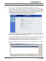
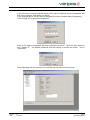
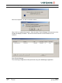
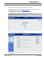
1
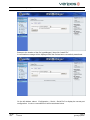
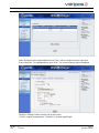
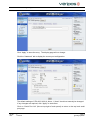
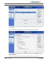
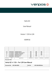
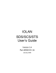
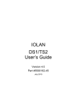
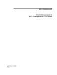
type44legacy Manual
VERIPOS
A
15/06/2012
REVISION
DATE
Released for Use
DESCRIPTION
KC
EM
EM
ORIGINATOR
CHECKED
APPROVED
Document Title:
Type44Legacy IOLAN Manual
Document No:
AB-V-MA-00542
File Ref:
AB-V-MA-00542.doc
CLIENT APPR
Document title:
Document No.
type44legacy Manual
AB-V-MA-00542
CONTENTS
1.
INTRODUCTION .............................................................................................................................................3
2.
INSTALLATION OF SDS 2-PORT IOLAN SYSTEM......................................................................................4
3.
CONFIGURATION OF PERLE SDS 2-PORT IOLAN ....................................................................................6
3.1
3.2
Rev No:
Date:
ASSIGNING AN IP ADDRESS AND UPGRADING FIRMWARE (IF REQUIRED) ...............................7
INSTALLING AND CONFIGURING THE CUSTOM APPLICATION ................................................. 11
A
15 06 2012
Page 2
type44legacy Manual
Document title:
Document No.
1.
type44legacy Manual
AB-V-MA-00542
INTRODUCTION
This manual covers the:
installation
configuration
of the VERIPOS Type44Legacy IOLAN unit.
The Type-44-Legacy IOLAN consists of a Perle IOLAN with VERIPOS custom application
firmware installed.
It is used to change the format of the Ultra Type 44 correction message from any VERIPOS
L-Band demodulator to make it compatible with legacy software applications.
The Type-44-Legacy IOLAN is designed to be inserted in the RS232 data link between a
VERIPOS demodulator and the legacy system. It will detect any Type 44 message, if
present, and will convert it the old Pseudo Type 1 format. All other corrections will pass
through unchanged.
If the demodulator is initially outputting Ultra corrections in pseudo Type 1 format, they will
be passed through unchanged. When the format switches to Type 44, the application will
automatically detect the change and will convert the corrections to pseudo Type 1.
The Type-44-Legacy application software has been tested on both 2-port Perle SDS
IOLANs and 16-port Perle STS IOLANs.
The following notes describe the preparation and installation of the SDS 2-port unit.
This is recommended for installations where only a limited number of VERIPOS RTCM
data streams are available.
The use of a separate IOLAN for each demodulator avoids introducing a single point of
failure which would nullify the system redundancy achieved by providing multiple
demodulators.
Perle STS 16-port IOLANs may be used for more complex installations where there are a
greater number of data streams and/or an IOLAN is already installed to implement the
NTRIP system.
These systems will be more complex and will be specific to a particular installation.
VERIPOS will provide the appropriate documentation on a case-by-case basis for clients
requiring this type of installation. Please contact the VERIPOS Helpdesk who will forward
your query to the appropriate technical staff.
Rev No:
Date:
A
15 06 2012
Page 3
type44legacy Manual
Document title:
Document No.
2.
type44legacy Manual
AB-V-MA-00542
INSTALLATION OF SDS 2-PORT IOLAN SYSTEM
The SDS two-port IOLAN is shown above. The front face has two RJ45 connectors which
are used for the serial ports. The unit is powered by a small AC/DC power unit which is
supplied as part of the installation kit. The installation kit also includes two short network
patch cables and the necessary D9/RJ45 adapters to connect to the existing hardware.
The unit is installed at the RTCM output of the VERIPOS demodulator. A typical
installation is shown below. All items outlined in blue will be provided in the installation kit:
Rev No:
Date:
A
15 06 2012
Page 4
type44legacy Manual
Document title:
Document No.
type44legacy Manual
AB-V-MA-00542
All the parts normally required are included in the installation kit.
Veripos will supply a wall-mount AC/DC power adapter suitable for use in a UK power
socket.
The IOLANs will be supplied by VERIPOS with the software already installed and fully
configured. The ports should be clearly marked to indicate which is input and which is
output. It will only be necessary for the installer to connect the IOLAN as shown in the
above diagram and then connect the power.
Rev No:
Date:
A
15 06 2012
Page 5
type44legacy Manual
Document title:
Document No.
3.
type44legacy Manual
AB-V-MA-00542
CONFIGURATION OF PERLE SDS 2-PORT IOLAN
The IOLANs will be prepared by installing and configuring the custom application software.
The IOLAN should be clearly mark to indicate which ports are designated for I/P and O/P.
The procedure detailed below configures “SERIAL 1” as the input and “SERIAL 2” as the
output.
It is recommended to also mark the IOLAN with its assigned IP address.
This will enable the use of integral WebManager application if reconfiguration (such as
changing baud rate) becomes necessary in the field.
VERIPOS will supply each IOLAN as a kit which includes the necessary D9/modular
adapters, network patch cables and AC/DC power adapter. (See above diagram.)
The female D9/modular adapter used to connect the IOLAN output to the existing RS232
cabling is supplied by Perle with each new two-port SDS IOLAN.
The male D9/modular adapter used to connect the IOLAN to the demodulator must be
sourced separately. It is recommended that only three wires should be connected, as
shown:
D9 pin
RJ45 pin
Wire colour
2
5
green
3
4
red
5
6
yellow
Note: The wire colours shown are applicable to several brands of adapters currently in use.
They are not guaranteed to be the same for all available brands.
Note: The power adapter supplied by Perle is specified for 100-240v @ 50/60Hz and is
integral with a UK power plug.
IOLAN Types and Firmware:
This document is specific to the Perle SDS 2-port IOLAN
Firmware version 4.4.G3 must be installed
Required Software
The software consists of a single file called type44legacy. This file must be obtained from
VERIPOS. If required contact the VERIPOS Helpdesk.
Before commencing the upgrade, the IOLAN firmware version must be checked.
Only firmware version 4.4.G3 should be used. If a different version is installed, the unit
must be upgraded as described below.
The necessary firmware file “IOLAN_Desk_v4.4.G3.bin” may be downloaded from the Perle
Web site at: http://www.perle.com/downloads/server_sds_2_4.shtml
Note: If using a 16 Port STS IOLAN the file should be IOLAN_RACK_v4.4.G3.bin available
at http://www.perle.com/downloads/server_sds_sts_rackmount.shtml
Rev No:
Date:
A
15 06 2012
Page 6
type44legacy Manual
Document title:
Document No.
3.1
type44legacy Manual
AB-V-MA-00542
ASSIGNING AN IP ADDRESS AND UPGRADING FIRMWARE (IF REQUIRED)
The installation of the application software is accomplished using the “WebManager”
application which is built into the IOLAN. New units, however, have no IP address assigned
so an appropriate address must be configured using the Device Manager application before
WebManager may be used. Device Manager is included on the CD supplied with new
units. It is also used to install the firmware upgrade if this is required.
The software CD should auto-start with the opening menu shown below:
Select the “DeviceManager” button to install the application onto a suitable Windows PC.
The PC must have an Ethernet connection. The installation presents several confirmation
screens. It is only necessary to accept the defaults.
Before opening Device Manager, temporarily disconnected the computer from any local
network and configure it with a fixed IP address. (Device Manager will search for
connected IOLAN units and confusion may arise is other units are found.)
Use a standard patch cable to connect the computer to the Ethernet port of the IOLAN.
Open Device Manager. Within a few seconds, it should report details of the attached
IOLAN:
Rev No:
Date:
A
15 06 2012
Page 7
type44legacy Manual
Document title:
Document No.
type44legacy Manual
AB-V-MA-00542
If the unit has the correct firmware version and a valid IP address which is compatible with
that of the computer, skip section 3.2 below.
In the example above, the unit has no assigned IP and the firmware requires upgrading.
Press “Assign IP” to open the dialog below:
Enter an IP which is compatible with that configured on the PC. Note the value and then
click “Assign IP”. The default password must be entered to confirm the action. This is
“superuser”:
Device Manager will now connect to the IOLAN and the main screen will open:
Rev No:
Date:
A
15 06 2012
Page 8
type44legacy Manual
Document title:
Document No.
type44legacy Manual
AB-V-MA-00542
If the correct firmware is installed, close the application and skip to section 3.2 below.
If the firmware requires upgrading, select “Tools/Advanced/Download Firmware to IOLAN”
from the main menu:
Browse to file “IOLAN_Desk_v4.4.G3.bin” then click “Open”:
Click “Yes” in the confirmation box to begin the download. A progress bar will be displayed
during the download and then another will open during the copy to flash:
Rev No:
Date:
A
15 06 2012
Page 9
type44legacy Manual
Document title:
Document No.
type44legacy Manual
AB-V-MA-00542
After this completes, you will be invited to reboot:
Click “Yes” to complete the process. After the reboot, Device Manager will reconnect to the
IOLAN and display its details. This should confirm that the correct firmware is now
installed:
Close Device Manager.
The remaining configuration will be performed using the WebManager application.
Rev No:
Date:
A
15 06 2012
Page 10
type44legacy Manual
Document title:
Document No.
3.2
type44legacy Manual
AB-V-MA-00542
INSTALLING AND CONFIGURING THE CUSTOM APPLICATION
Open Internet Explorer and enter the IP address previously configured for the IOLAN.
For the example above, this would be: http://192.168.0.22
The WebManager login screen will open.
The required Username is “admin”; the Password is “superuser”:
The main WebManager screen will then open:
In the left sidebar, select “Administration – Custom Files” to open the Custom File
installation dialog:
Rev No:
Date:
A
15 06 2012
Page 11
type44legacy Manual
Document title:
Document No.
type44legacy Manual
AB-V-MA-00542
Browse to the location of the file “type44legacy” then click “Install File”
A confirmation message will be displayed after the file has been successfully transferred:
On the left sidebar, select: “Configuration – Serial – Serial Port” to display the current port
configuration. A new or unmodified unit will be as shown below:
Rev No:
Date:
A
15 06 2012
Page 12
type44legacy Manual
Document title:
Document No.
type44legacy Manual
AB-V-MA-00542
Note: By following the steps detailed below, Port 1 will be configured as the input port.
Ensure that Port 1 is highlighted then click “Edit”. The current settings will be displayed:
Click the “Change” button near the top of the screen.
“Profile” must be changed from “Terminal” to “Custom App/Plugin”:
Rev No:
Date:
A
15 06 2012
Page 13
type44legacy Manual
Document title:
Document No.
type44legacy Manual
AB-V-MA-00542
The initial selection will be “Terminal”.
Change this to “Custom App/Plugin” then click “Apply”.
After a (lengthy) delay, WebManager will switch back the previous display page but will
now show the updated Profile and a “Command Line” entry box:
In the Command Line box, enter the text: “type44legacy –o1” as shown below:
Note that the ports are internally number as 0 and 1 so this configures “SERIAL 2” as the
output port:
Rev No:
Date:
A
15 06 2012
Page 14
type44legacy Manual
Document title:
Document No.
type44legacy Manual
AB-V-MA-00542
Click “Apply” to store the entry. The display page will not change.
Click the “Hardware” tab to display the current port configuration:
The default settings of “EIA-232, 9600, 8, None, 1, None” should not normally be changed.
If any changes are required, click “Apply” to store them.
Click on “Serial Port List” (blue at top-right of main panel) to return to the top level serial
port page:
Rev No:
Date:
A
15 06 2012
Page 15
type44legacy Manual
Document title:
Document No.
type44legacy Manual
AB-V-MA-00542
Note that Port 1 now shows the correct Profile and that the Command Line entry is shown
under “Details”.
Click in the Port 2 row to highlight it then click “Edit” to show the Port 2 details:
Port 2 should be configured exactly as for Port 1 except that the “Command Line” box
must be left blank.
When this is completed, the top level serial port page should be as shown below:
Rev No:
Date:
A
15 06 2012
Page 16
type44legacy Manual
Document title:
Document No.
type44legacy Manual
AB-V-MA-00542
The unit must be rebooted to complete the configuration.
Click the “Reboot IOLAN” button at the bottom right of the screen.
Click “Yes” in the confirmation dialog. Rebooting will take more than 90 seconds:
On successful completion, WebManager will connect to the IOLAN and the login screen will
be displayed:
Rev No:
Date:
A
15 06 2012
Page 17
type44legacy Manual
Document title:
Document No.
type44legacy Manual
AB-V-MA-00542
WebManager may now be closed and the Ethernet cable disconnected.
It is recommended that the IP address should be marked on the unit in case a change of
baud rate is required in the field.
If the IP is unknown, it can only be determined using the Device Manager software which
might not be easily available.
THIS COMPLETES THE CONFIGURATION OF THE UNIT.
Rev No:
Date:
A
15 06 2012
Page 18
type44legacy Manual