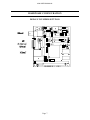
1
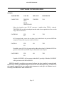
4I29 ETHERNET INTERFACE MANUAL
VERSION 1.6
Copyright 1997 by MESA ELECTRONICS Richmond, CA. Printed in the United States of
America. All rights reserved. This document and the data disclosed herein is not to be reproduced,
used, disclosed in whole or in part to anyone without the written permission of MESA
ELECTRONICS.
Mesa Electronics
4175 Lakeside Drive, Suite #100
Richmond, CA 94806-1950
Tel (510) 223-9272 - Fax (510) 223-9585
E-Mail: [email protected] - Website: www.mesanet.com
4I29 USER'S MANUAL
4I29 USER'S MANUAL
TABLE OF CONTENTS
HANDLING PRECAUTIONS
Handling precautions . . . . . . . . . . . . . . . . . . . . . . . . . . . . . . . . . . . . . . . . . . . . . . . . . . . . . . . . . . . . . . . . . . 4
INTRODUCTION
General . . . . . . . . . . . . . . . . . . . . . . . . . . . . . . . . . . . . . . . . . . . . . . . . . . . . . . . . . . . . . . . . . . . . . . . . . . . . . . . . 5
HARDWARE CONFIGURATION
General . . . . . . . . . . . . . . . . . . . . . . . . . . . . . . . . . . . . . . . . . . . . . . . . . . . . . . . . . . . . . . . . . . . . . . . . . . . . . . . .
Default hardware configuration . . . . . . . . . . . . . . . . . . . . . . . . . . . . . . . . . . . . . . . . . . . . . . . . . . . . . . . .
Default software configuration. . . . . . . . . . . . . . . . . . . . . . . . . . . . . . . . . . . . . . . . . . . . . . . . . . . . . . . . .
External 10Base2 Tranceiver . . . . . . . . . . . . . . . . . . . . . . . . . . . . . . . . . . . . . . . . . . . . . . . . . . . . . . . . . .
Panel mount 10BaseT option . . . . . . . . . . . . . . . . . . . . . . . . . . . . . . . . . . . . . . . . . . . . . . . . . . . . . . . . . .
Termination. . . . . . . . . . . . . . . . . . . . . . . . . . . . . . . . . . . . . . . . . . . . . . . . . . . . . . . . . . . . . . . . . . . . . . . . . . . .
Bus size selection . . . . . . . . . . . . . . . . . . . . . . . . . . . . . . . . . . . . . . . . . . . . . . . . . . . . . . . . . . . . . . . . . . . . . .
6
6
6
8
8
8
8
SOFTWARE CONFIGURATION
General . . . . . . . . . . . . . . . . . . . . . . . . . . . . . . . . . . . . . . . . . . . . . . . . . . . . . . . . . . . . . . . . . . . . . . . . . . . . . . . . 9
SET4I29 . . . . . . . . . . . . . . . . . . . . . . . . . . . . . . . . . . . . . . . . . . . . . . . . . . . . . . . . . . . . . . . . . . . . . . . . . . . . . . . 9
QUICKSET . . . . . . . . . . . . . . . . . . . . . . . . . . . . . . . . . . . . . . . . . . . . . . . . . . . . . . . . . . . . . . . . . . . . . . . . . . 13
LINKOK . . . . . . . . . . . . . . . . . . . . . . . . . . . . . . . . . . . . . . . . . . . . . . . . . . . . . . . . . . . . . . . . . . . . . . . . . . . . . 13
SHOW4I29 . . . . . . . . . . . . . . . . . . . . . . . . . . . . . . . . . . . . . . . . . . . . . . . . . . . . . . . . . . . . . . . . . . . . . . . . . . . 13
I/O CONNECTORS
BNC Connector . . . . . . . . . . . . . . . . . . . . . . . . . . . . . . . . . . . . . . . . . . . . . . . . . . . . . . . . . . . . . . . . . . . . . . . 14
Twisted Pair connector . . . . . . . . . . . . . . . . . . . . . . . . . . . . . . . . . . . . . . . . . . . . . . . . . . . . . . . . . . . . . . . 14
AUI connector . . . . . . . . . . . . . . . . . . . . . . . . . . . . . . . . . . . . . . . . . . . . . . . . . . . . . . . . . . . . . . . . . . . . . . . . 14
External transceiver option . . . . . . . . . . . . . . . . . . . . . . . . . . . . . . . . . . . . . . . . . . . . . . . . . . . . . . . . . . . 14
INSTALLATION
General . . . . . . . . . . . . . . . . . . . . . . . . . . . . . . . . . . . . . . . . . . . . . . . . . . . . . . . . . . . . . . . . . . . . . . . . . . . . . . . 14
REFERENCE INFORMATION
Specifications . . . . . . . . . . . . . . . . . . . . . . . . . . . . . . . . . . . . . . . . . . . . . . . . . . . . . . . . . . . . . . . . . . . . . . . . . 16
Warranty. . . . . . . . . . . . . . . . . . . . . . . . . . . . . . . . . . . . . . . . . . . . . . . . . . . . . . . . . . . . . . . . . . . . . . . . . . . . . . 17
Schematic diagrams . . . . . . . . . . . . . . . . . . . . . . . . . . . . . . . . . . . . . . . . . . . . . . . . . . . . . . . . . . . . . . . . . . . 19
4I29 USER'S MANUAL
HANDLING PRECAUTIONS
STATIC ELECTRICITY
The CMOS integrated circuits on the 4I29 can be damaged by exposure to electrostatic
discharges. The following precautions should be taken when handling the 4I29 to prevent possible
damage.
A. Leave the 4I29 in its antistatic bag until needed.
B. All work should be performed at an antistatic workstation.
C. Ground equipment into which 4I29 will be installed.
D. Ground handling personnel with conductive bracelet through 1 megohm resistor to ground.
E. Avoid wearing synthetic fabrics, particularly Nylon.
Page 4
4I29 USER'S MANUAL
INTRODUCTION
GENERAL
The 4I29 is a 16 bit Ethernet interface implemented on a stackable PC/104 bus card. The 4I29
supports 10BaseT (Twisted pair) and 10Base2 (Thin-BNC) Ethernet, plus has an AUI connector for
connection to external transceivers. The 4I29 can also be supplied with a low cost external panel
mount BNC transceiver for applications where access to the 4I29 card is restricted.
The 4I29 can be compatible with the NE2000 or WD8013EBT depending on EEPROM setup
options.
Most 4I29 options are settable via a provided setup utility, there are only three option jumpers
(8/16 bit bus select and 10Base2 termination, local tranceiver power). Setup options are stored in an
on card EEPROM, so that the setup utility need only be run when changing hardware settings.
Programmable options include emulation mode (NE2000 or WD8013EBT), I/O address, boot
PROM enable, boot PROM location, boot PROM size, interrupt select, and 10BaseT / 10Base2 /
AUI selection. Selectable interrupts are IRQ2, IRQ3, IRQ4, IRQ5, IRQ10, IRQ11, and IRQ12.
The 10Base2 DC-DC converter can be turned off to minimize power when idle, and is
automatically disabled when the 4I29 is setup for twisted pair use. The all CMOS design of the 4I29
plus efficient DC-DC converter keeps operating power below 2 watts.
Standard packet buffer is 16K bytes but a 64K byte buffer version is available if desired.
A 32 pin dip socket allows installation of 28 or 32 pin boot PROMs from network vendors. The
4I29 is capable of writing to the boot PROM, allowing use of a 5V flash boot PROM if desired.
Page 5
4I29 USER'S MANUAL
HARDWARE CONFIGURATION
GENERAL
The 4I29 has only three hardware configuration options, as most 4I29 configuration is done via
the provided software configuration utility. The hardware options are 10Base2 (BNC) termination, 8
bit/AUTO bus size selection and local tranceiver power disconnect. The options are selected with
shorting jumpers placed on three pin headers. In the following discussions, when the words "up",
"down", "right", and "left" are used it is assumed that the 4I29 card is oriented with its bus connectors
J1 and J2 at the bottom edge of the card (nearest the person doing the configuration).
DEFAULT HARDWARE CONFIGURATION
The 4I29 card is configured in the following manner when shipped from the factory.
FUNCTION
DEFAULT
JUMPER
POSITION
LOCAL XCVR POWER
TERMINATION
BUS SIZE
ENABLED
DISABLED
AUTO
W1
W2
W3
UP
DOWN
LEFT
DEFAULT SOFTWARE CONFIGURATION
The default EEPROM configuration on 4I29 card as shipped from the factory is as follows:
PARAMETER
VALUE
MAINMODE
COMPATIBLE
PORTADD
INTERRUPT
PROMLOC
CABLETYPE
FASTREAD
FASTIO16
FASTCHRDY
IOMAPPED
YES
300
IRQ5
NONE
THIN
NO
NO
NO
Page 6
4I29 USER'S MANUAL
HARDWARE CONFIGURATION
DEFAULT JUMPER SETTINGS
Page 7
4I29 USER'S MANUAL
HARDWARE CONFIGURATION
EXTERNAL 10BASE2 TRANCEIVER
The 4I29 can use an optional external 10base2 (BNC) tranceiver module from MESA. This small
circuit card module can be panel mounted up to 1 foot away from the 4I29 card. This circuit card is
called the MAU and is included with the 4I29-E model.
If the external BNC tranceiver is used, you must disconnect the local tranceivers power. This is
done by moving W1 to the down position. The 4I29 setup must use the 'THIN' cable selection when
using the MAU, as the MAU's power comes from the local tranceiver power supply
It is not necessary to change the default (enabled) W1 position when selecting between thin, thick,
or twisted pair interfaces, as the hardware on the 4I29 card enables the DC-DC converter only when
the thin ethernet interface is selected.
PANEL MOUNT 10BASET OPTION
If the RJ45 connector on the 4I29 is not located in a convenient place for the 10BaseT cable, an
optional adapter is available from MESA that allows remote mounting of the RJ45 connector up to 1
foot away from the 4I29. The part name of this adapter is TAU. The TAU also has link status, receive,
and transmit LEDs.
TERMINATION
The 10Base2 input (BNC) can be terminated on the 4I29 card. This eliminates the need for the
TEE fitting + BNC terminator at the end of the line, and is very convenient for simple two or three
node nets. The on card termination should not be used if the Ethernet cabling is subject to frequent
change, as it is easy to forget that a card is terminated internally. The internal termination is enabled by
setting the shorting jumper on jumper block W1 in the UP position. Setting the jumper to the DOWN
position disables the internal termination.
BUS SIZE SELECTION
The 4I29 can work with 8 and 16 bit CPU's. Bus size is normally selected automatically by sensing
the voltage on the PC/104 bus J2 connector pin 34. This is a 5V line on the AT part of the bus
connector. If 5V is sensed on this line, an AT type CPU is assumed, and 16 bit bus transfers are used.
This scheme is not guaranteed to work in all circumstances. For example, if other I/O cards with the J2
connector are used, pin 34 of J2 may be tied to +5V even with an XT type CPU. Because of this
possibility, the 4I29 can be forced to work in 8 bit mode if required.
If the shorting jumper on jumper block W2 is placed in the left hand position, automatic bus sizing
is enabled. If the shorting jumper is placed in the right hand position, the 4I29 is forced into the 8 bit
mode.
Page 8
4I29 USER'S MANUAL
SOFTWARE CONFIGURATION
GENERAL
Most 4I29 setup options are stored in an on card EEPROM. This includes I/O address, interrupt
line selection, Boot PROM enable, size ,and location, selection of compatibility mode, and various
timing options.
Two setup utility programs are supplied with the 4I29. These programs allow you to change these
parameters and display the current card setup.
SET4I29
SET4I29 is a utility program for setting 4I29 EEPROM options. SET4I29 is invoked with two or
optionally three command line parameters, a port address, a file name, and an 'I' for immediate mode:
SET4I29 300 WD8013.CFG [I]
The port address will be 300 the first time SET4I29 is used, because all 4I29 cards are shipped
from MESA configured for that location. All port addresses are in hexadecimal. Once a 4I29 card has
been configured to a different port address, you need to specify the new port address when running
SET4I29.
Because it is possible to forget the port location of a 4I29 card, the port address on the command
line can be replaced with 'S' or '?'. This causes SET4I29 to look for the 4I29 card by probing all of the
possible 4I29 I/O addresses. You should not use the (S)earch option if you know the 4I29 port
address, as it is not guaranteed to work in all cases.
The second command line parameter is the name of the configuration file. The configuration file is
an ASCII file containing the configuration parameters. The 4I29 distribution disk has two example
configuration files, NE2000.CFG and WD8013.CFG. You should use these files as a starting point to
creating your own configuration files. The format of the configuration file is very simple: each line of
the configuration file consists of a parameter name followed by a parameter value. If a parameter
name is not specified in the configuration file, that parameter will be set to the default value shown in
the following table. Note that the defaults in the following table are not the same as the factory
default options.
The third parameter is the optional 'I'. The I stands for Immediate. When I is specified, the set
utility does not change the EEPROM setup values, but only changes the current 4I29 operating
parameters. These changes take effect immediately, but only last until the next hardware reset. This
can be used for trying different setups before commiting them to permanent storage in the EEPROM.
Certain 4I29 parameters cannot be changed in the immeditate mode. If a configuration file that
includes parameters that cannot be changed in the immediate mode is used in the immediate mode,
warnings will be printed, and those parameter changes will be ignored.
Page 9
4I29 USER'S MANUAL
SOFTWARE CONFIGURATION
SET4I29
The following table shows SET4I29 parameter names, parameter values, default parameter
values, and whether the parameter can be changed in immediate mode:
PARAMETER
VALUES
DEFAULT
IMMEDIATE
MAINMODE
IOMAPPED
MEMMAPPED
IOMAPPED
NO
Main mode sets the emulation mode of the 4I29 to I/O mapped (NE2000) or memory
mapped (WD8013) operation. Note that strict compatibility with the WD8013 mode is
not guaranteed with the National ATLANTIC chip. Therefore the NE2000 mode is
suggested.
COMPATIBLE
YES
NO
YES
NO
If COMPATIBLE is YES, the buffer mapping matches the standard size and location for
WD8013 and NE2000 compatibility. If COMPATIBLE is NO, and the 4I29 has 64K byes
of buffer RAM, all buffer RAM will be accessible.
PORTADD
240
280
2C0
300
320
340
360
300
YES
Sets the 4I29 port address. Make sure that no other card in the system uses the same I/O
address.
Page 10
4I29 USER'S MANUAL
SOFTWARE CONFIGURATION
SET4I29
PARAMETER
VALUES
DEFAULT
IMMEDIATE
INTERRUPT
NONE
IRQ2
IRQ3
IRQ4
IRQ5
IRQ10
IRQ11
IRQ12
IRQ2
YES
Selects the IRQ line that the 4I29 will drive. Make sure that no other card in the system
uses the same interrupt line.
PROMLOC
NONE
C000-16K
C400-16K
C800-16K
CC00-16K
D000-16K
D400-16K
D800-16K
DC00-16K
C000-32K
C800-32K
D000-32K
D800-32K
C000-64K
D000-64K
NONE
NO
Selects the boot PROM location and size. NONE means that the boot PROM is disabled.
Make sure that the boot PROM location does not overlap any memory in the system.
Page 11
4I29 USER'S MANUAL
SOFTWARE CONFIGURATION
SET4I29
PARAMETER
VALUES
DEFAULT
CABLETYPE
TWISTED
TWISTED
THIN
THICK
TWISTEDLOW
IMMEDIATE
YES
Selects the interface type. DC-DC converter is enabled when THIN is selected.
TWISTEDLOW uses the twisted pair interface with a lower squelch level for use with
longer than normal cables.
FASTREAD
YES
NO
NO
YES
In I/O mapped mode, causes the next data to be fetched before the previous IORD has
completed. Only enable in systems with fast ISA bus!
FASTIO16
YES
NO
NO
YES
If enabled, causes IOCS16 to be generated by address decode only. If disabled, IOCS16 is
generated with IORD, and IOWR. May be needed with some chip sets.
FASTCHRDY
YES
NO
NO
YES
If enabled, IOCHRDY will be generated when BALE goes high. If disabled, IOCHRDY
will be generated with IORD and IOWR.
SET4I29 should be run before any network software has been installed or unpredictable
behavior may result! After SET4I29 has been run (in the non-immediate mode), you must reset
the computer system for the new configuration parameters to take effect. A hardware reset is
necessary, CONTROL-ALT-DEL will not work!
Page 12
4I29 USER'S MANUAL
SOFTWARE CONFIGURATION
QUICKSET
QUICKSET is a similar utility to SET4I29 except that is can only change one 4I29 parameter at a
time and the parameter to be changed is supplied on the command line. QUICKSET only changes the
4I29 register vaulues, not the EEPROM, so that the 4I29 will return to its previous configuration after
a system reset. QUICKSET is invoked with the hexadecimal port address on the command line:
QUICKSET 300 PARAMETER VALUE
Where PARAMETER and VALUE are the same parameters and values that SET4I29 uses. For
example:
QUICKSET 320 CABLETYPE THIN
Would set the 4I29 at 0320H to use the BNC interface.
LINKOK
LINKOK is a simple utility to test the status of the 10BaseT link, and optionally switch the 4I29
cable type to 10 baseT. LINKOK is invoked with the hexadecimal port address on the command line:
LINKOK 300 [AUTO]
If the optional parameter AUTO is supplied, LINKOK will change the CABLETYPE setting to
10BASET if the 10BaseT link status is ok. This can be used to automatically select the 10BaseT port
if the RJ 45 cable is installed. The CABLETYPE will revert to the original 4I29 card settings after a
hardware reset. LINKOK should be run before any network software.
SHOW4I29
SHOW4I29 is a utility program that displays some of the current 4I29 setup parameters and the
4I29 Ethernet address. The COMPATIBLE option and the PROMLOC option are not readable, so
they are not displayed. SHOW4I29 is invoked with the hexadecimal port address on the command
line:
SHOW4I29 300
Because it is possible to forget the port location of a 4I29 card, the port address on the command
line can be replaced with 'S' or'?'. This causes SHOW4I29 to look for the 4I29 card by probing all of
the possible 4I29 I/O addresses. You should not use the (S)earch option if you know the 4I29 port
address, as it is not guaranteed to work in all cases.
SHOW4I29 should not be run after network software is installed, or unpredictable behavior
may result.
Page 13
4I29 USER'S MANUAL
INTERFACE CONNECTORS
10BASE2 CONNECTOR
Depending on 4I29 model, the 4I29 may have a BNC connector for connection to 10Base2
(Cheapernet) networks. This connector is marked P1. When the BNC connector is used, a BNC TEE
must be connected to the 4I29's BNC connector if the Ethernet coax does not end at the 4I29. If the
coax ends at the 4I29, a 50 Ohm terminator must be installed. This terminator can be a BNC
terminator if the BNC TEE is used, or the internal 4I29 termination option can be used.
10BASET CONNECTOR
Depending on 4I29 model, the 4I29 may have a 8 pin modular telephone type jack for use with
10BaseT twisted pair networks.This connector is marked P5. When twisted pair networks are used, a
10BaseT hub must be supplied. You cannot simply connect from one interface card to another when
twisted pair cable is used.
AUI CONNECTOR
An AUI connector is provided for connecting to external transceivers. This connector is a 16 pin
header. When a flat cable with a female header at one end, and a female D-SUB connector at the other
end is plugged onto the 16 pin header, the D-SUB pinout matches the AUI standard pinout. This flat
cable is available from MESA. If you make your own cable, note that pin 16 of the flat cable is not
used. The flat cable should be less than one foot long, as it is not a good impedance match to the 78
Ohm twisted pair transceiver cables. 12V power on the AUI connector is directly connected to the
PC/104 bus 12V system power.
EXTERNAL TRANCEIVER OPTION
The 4I29 is available with a low cost external 10Base2 tranceiver option. This panel mount BNC
tranceiver allows simple external access to the 10Base2 connector without depending on the PC/104
stack location. This tranceiver connects to the 4I29's AUI connector with a 20 pin flat cable and gets
its isolated power from the 4I29's DC-DC converter. This flat cable must be 1 foot or shorter in length
. When installing the flat cable, make sure that the pin one mark on the cable is aligned with the white
dot on connector P4. When the external tranceiver is used, you must also move jumper W1 to the
down position to disconnect the local BNC tranceiver.
Page 14
4I29 USER'S MANUAL
INSTALLATION
GENERAL
When the 4I29 has been properly configured for its application, it can be inserted into a PC/104
stack. The standoffs should then be tightened to secure the 4I29 in its place. When the 4I29 is secured
in the stack the I/O connectors can be plugged in from the side.
Page 15
4I29 USER'S MANUAL
REFERENCE INFORMATION
SPECIFICATIONS
MIN
MAX
UNIT
NOTES
POWER SUPPLY
Voltage
Supply current (5V)
Supply current (5V)
4.5
-----
5.5
125
250
V
mA
mA
(AUI, 10BaseT)
(10Base2)
BUS LOADING:
Input capacitance
Input leakage current
Output drive capability
Output sink current
----150
12
15
5
-----
pF
uA
pF
mA
ENVIRONMENTAL:
Operating temperature range
-I version
-C version
Relative humidity
-40
0
0
+85
+70
90
o
Page 16
C
C
Percent
Non-condensing
o
4I29 USER'S MANUAL
REFERENCE INFORMATION
WARRANTY
Mesa Electronics warrants the products it manufactures to be free effects in material and
workmanship under normal use and service for the period of 2 years from date of purchase. This
warranty shall not apply to products which have been subject to misuse, neglect, accident, or
abnormal conditions of operation.
In the event of failure of a product covered by this warranty, Mesa Electronics, will repair any
product returned to Mesa Electronics within 2 years of original purchase, provided the warrantor's
examination discloses to its satisfaction that the product was defective. The warrantor may at its
option, replace the product in lieu of repair.
With regard to any product returned within 2 years of purchase, said repairs or replacement will be
made without charge. If the failure has been caused by misuse, neglect, accident, or abnormal
conditions of operation, repairs will be billed at a nominal cost.
THE FOREGOING WARRANTY IS IN LIEU OF ALL OTHER WARRANTIES,
EXPRESS OR IMPLIED. INCLUDING BUT NOT LIMITED TO ANY IMPLIED
WARRANTY OF MERCHANTABILITY, FITNESS, OR ADEQUACY FOR ANY
PARTICULAR PURPOSE OR USE. MESA ELECTRONICS SHALL NOT BE LIABLE FOR
ANY SPECIAL, INCIDENTAL, OR CONSEQUENTIAL DAMAGES, WHETHER IN
CONTRACT, TORT, OR OTHERWISE.
If any failure occurs, the following steps should be taken:
1. Notify Mesa Electronics, giving full details of the difficulty. On receipt of this information,
service data, or shipping instructions will be forwarded to you.
2. On receipt of the shipping instructions, forward the product, in its original protective
packaging, transportation prepaid to Mesa Electronics. Repairs will be made at Mesa Electronics and
the product returned transportation prepaid.
Page 17
4I29 USER'S MANUAL
REFERENCE INFORMATION
THIS PAGE INTENTIONALLY LEFT ALMOST BLANK
Page 18
4I29 USER'S MANUAL
REFERENCE INFORMATION
SCHEMATICS
Page 19