1
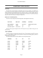
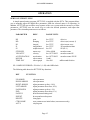
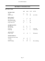
4I27A MOTOR CONTROLLER - ANALOG
VERSION 1.2
Copyright 1997 by MESA ELECTRONICS Richmond,CA. Printed in the United States of
America. All rights reserved. This document and the data disclosed herein is not to be reproduced,
used, disclosed in whole or in part to anyone without the written permission of MESA
ELECTRONICS.
Mesa Electronics
4175 Lakeside Drive, Suite #100
Richmond, CA 94806-1950
Tel (510) 223-9272 - Fax (510) 223-9585
E-Mail: [email protected] - Website: www.mesanet.com
4I27A USER'S MANUAL
4I27A USER'S MANUAL
TABLE OF CONTENTS
WARNINGS
Servo hazards . . . . . . . . . . . . . . . . . . . . . . . . . . . . . . . . . . . . . . . . . . . . . . . . . . . . . . . . . . . . . . . . . . . . . . . . . . 4
Handling precautions . . . . . . . . . . . . . . . . . . . . . . . . . . . . . . . . . . . . . . . . . . . . . . . . . . . . . . . . . . . . . . . . . . 4
INTRODUCTION
General . . . . . . . . . . . . . . . . . . . . . . . . . . . . . . . . . . . . . . . . . . . . . . . . . . . . . . . . . . . . . . . . . . . . . . . . . . . . . . . . 5
HARDWARE CONFIGURATION
General . . . . . . . . . . . . . . . . . . . . . . . . . . . . . . . . . . . . . . . . . . . . . . . . . . . . . . . . . . . . . . . . . . . . . . . . . . . . . . . .
Default configuration . . . . . . . . . . . . . . . . . . . . . . . . . . . . . . . . . . . . . . . . . . . . . . . . . . . . . . . . . . . . . . . . . .
Port address. . . . . . . . . . . . . . . . . . . . . . . . . . . . . . . . . . . . . . . . . . . . . . . . . . . . . . . . . . . . . . . . . . . . . . . . . . . .
LM628 clock . . . . . . . . . . . . . . . . . . . . . . . . . . . . . . . . . . . . . . . . . . . . . . . . . . . . . . . . . . . . . . . . . . . . . . . . . .
Default motor-enable polarity. . . . . . . . . . . . . . . . . . . . . . . . . . . . . . . . . . . . . . . . . . . . . . . . . . . . . . . . . .
6
6
6
8
8
INTERFACE CONNECTOR
General . . . . . . . . . . . . . . . . . . . . . . . . . . . . . . . . . . . . . . . . . . . . . . . . . . . . . . . . . . . . . . . . . . . . . . . . . . . . . . . . 9
I/O connector orientation . . . . . . . . . . . . . . . . . . . . . . . . . . . . . . . . . . . . . . . . . . . . . . . . . . . . . . . . . . . . . . 9
RS-422 interface connector pinout . . . . . . . . . . . . . . . . . . . . . . . . . . . . . . . . . . . . . . . . . . . . . . . . . . . . . 9
INSTALLATION
General . . . . . . . . . . . . . . . . . . . . . . . . . . . . . . . . . . . . . . . . . . . . . . . . . . . . . . . . . . . . . . . . . . . . . . . . . . . . . . . 10
OPERATION
Register map . . . . . . . . . . . . . . . . . . . . . . . . . . . . . . . . . . . . . . . . . . . . . . . . . . . . . . . . . . . . . . . . . . . . . . . . . . 11
Parallel port . . . . . . . . . . . . . . . . . . . . . . . . . . . . . . . . . . . . . . . . . . . . . . . . . . . . . . . . . . . . . . . . . . . . . . . . . . . 11
Parallel port bits . . . . . . . . . . . . . . . . . . . . . . . . . . . . . . . . . . . . . . . . . . . . . . . . . . . . . . . . . . . . . . . . . . . . . . . 12
Parallel port operation . . . . . . . . . . . . . . . . . . . . . . . . . . . . . . . . . . . . . . . . . . . . . . . . . . . . . . . . . . . . . . . . 13
Interrupt select . . . . . . . . . . . . . . . . . . . . . . . . . . . . . . . . . . . . . . . . . . . . . . . . . . . . . . . . . . . . . . . . . . . . . . . . 13
Interrupt mode . . . . . . . . . . . . . . . . . . . . . . . . . . . . . . . . . . . . . . . . . . . . . . . . . . . . . . . . . . . . . . . . . . . . . . . . 13
Interrupt operation. . . . . . . . . . . . . . . . . . . . . . . . . . . . . . . . . . . . . . . . . . . . . . . . . . . . . . . . . . . . . . . . . . . . 14
Connecting motors . . . . . . . . . . . . . . . . . . . . . . . . . . . . . . . . . . . . . . . . . . . . . . . . . . . . . . . . . . . . . . . . . . . 14
Servo system tuning . . . . . . . . . . . . . . . . . . . . . . . . . . . . . . . . . . . . . . . . . . . . . . . . . . . . . . . . . . . . . . . . . . . 15
Demonstration programs . . . . . . . . . . . . . . . . . . . . . . . . . . . . . . . . . . . . . . . . . . . . . . . . . . . . . . . . . . . . . 16
REFERENCE INFORMATION
Specifications . . . . . . . . . . . . . . . . . . . . . . . . . . . . . . . . . . . . . . . . . . . . . . . . . . . . . . . . . . . . . . . . . . . . . . . . . 17
Warranty. . . . . . . . . . . . . . . . . . . . . . . . . . . . . . . . . . . . . . . . . . . . . . . . . . . . . . . . . . . . . . . . . . . . . . . . . . . . . . 18
Schematic diagrams . . . . . . . . . . . . . . . . . . . . . . . . . . . . . . . . . . . . . . . . . . . . . . . . . . . . . . . . . . . . . . . . . . . 19
4I27A USER'S MANUAL
WARNINGS
SERVO WARNING
Large servo motors are capable of inflicting serious injury both to people and to
mechanisms associated with the servo system. In addition, some motors use potentially
lethal supply voltages.
When a servo control system is first configured, unpredictable behavior should be
EXPECTED. First time checks of basic servo operation (such as motor position versus
drive) should be checked with the motor power leads disconnected.
Never depend on software commands to the 4I27A to disable the motor when you or
others would be exposed to a hazard should the motor start unexpectedly. Motor power
should always be removed when working on mechanical parts of the servo system.
STATIC ELECTRICITY
The CMOS integrated circuits on the 4I27A can be damaged by exposure to electrostatic
discharges. The following precautions should be taken when handling the 4I27A to prevent
possible damage.
A. Leave the 4I27A in its antistatic bag until needed.
B. All work should be performed at an antistatic workstation.
C. Ground equipment into which 4I27A will be installed.
D. Ground handling personnel with conductive bracelet through 1 megohm resistor to
ground.
E. Avoid wearing synthetic fabrics, particularly Nylon.
Page 4
4I27A USER'S MANUAL
INTRODUCTION
GENERAL
The 4I27A is a low cost, LM628 based 2 axis DC servo motor control system implemented on a
stackable PC/104 bus card. The 4I27A is designed for high performance positioning systems using
DC servo motors with quadrature shaft encoders.
The per axis output of the 4I27A is a +- 10 volt signal that can drive analog input type servo
amplifiers directly.
The 4I27A quadrature encoder and index inputs are RS-422. This is desireable where long
encoder cables are required.
Control signals for each axis include 3 auxiliary I/O bits. These I/O bits may be used for overtemperature shutdown detect and servo amplifier enable. Eight general purpose I/O bits are available
for any application use.
The LM628's used on the 4I27A are high performance digital processors specifically designed for
motion control. The LM628 can execute a ramp-up, slew, and ramp-down motion sequence without
host processor intervention.
Host interrupts can be generated at end of motion, position breakpoints, index pulse, or in
response to various error conditions. Interrupts are or'ed on the 4I27A card, so that only one system
interrupt is used. The IRQ line used can be software selected from any of the 11 available AT bus
interrupts.
A digital PID filter is used to set loop feedback parameters for stability and optimum performance.
Velocity, target position and filter parameters may be changed during motion. The clock speed of the
LM628's can be lowered to accommodate large motors that require longer time constants.
Demonstration software includes examples of 2 axis position mode operation, velocity mode
operation, and a simple filter tuning program that allows dynamic filter coefficient modification while
providing a graphic display of the servo system step response. Source code is provided for all
demonstration software.
A PWM output version of the 4I27A is available as the 4I27.
Page 5
4I27A USER'S MANUAL
HARDWARE CONFIGURATION
GENERAL
The 4I27A has only three hardware configurable options, the I/O port address, the LM628 clock
speed, and the startup motor enable bit states. The options are selected with shorting jumpers placed
on three pin headers. In the following discussions, when the words "up", "down", "right", and "left"
are used it is assumed that the 4I27A card is oriented with its bus connectors J1 and J2 at the bottom
edge of the card (nearest the person doing the configuration).
DEFAULT CONFIGURATION
The 4I27A card is configured in the following manner when shipped from the factory.
FUNCTION
DEFAULT
JUMPERS
POSITION
PORT ADDRESS
LM628 CLOCK
MOTOR ENABLES
0200H
8 MHZ
PULLED-UP
W1,W2,W3
W4
W5
DOWN,DOWN,DOWN
LEFT
UP
Demonstration programs shipped with the 4I27A depend on the port address being left at the
default setting
PORT ADDRESS
The 4I27A occupies 16 contiguous locations in I/O space. The base address of the 4I27A card can
be any of eight different locations. These locations are selected with shorting jumpers placed on
jumper blocks W1,W2, and W3.
The following table shows the I/O base addresses selected by these jumpers:
ADDRESS
W1
W2
W3
0200H
0210H
0220H
0230H
0240H
0250H
0260H
0270H
DOWN
DOWN
DOWN
DOWN
UP
UP
UP
UP
DOWN
DOWN
UP
UP
DOWN
DOWN
UP
UP
DOWN
UP
DOWN
UP
DOWN
UP
DOWN
UP
Page 6
4I27A USER'S MANUAL
HARDWARE CONFIGURATION
PORT ADDRESS, CLOCK, AND MOTOR ENABLE JUMPERS
Page 7
4I27A USER'S MANUAL
HARDWARE CONFIGURATION
LM628 CLOCK
The LM628 motor controller chip on the 4I27A normally uses a 8 MHz clock. This clock can be
set to 4 MHz if desired.The maximum quadrature input rate will be reduced to 500 Khz when the 4
MHz clock option is selected. Moving W4 to the LEFT position sets the LM628 clock to 8Mhz.
Setting W4 to the RIGHT position sets the LM628 clock to 4 MHz.
DEFAULT MOTOR-ENABLE POLARITY
The motor enable bits on port A of the parallel port can be set to be pulled up or pulled down on
power up and system reset. These bits can then be used to disable an external servo amplifier at startup
to prevent unwanted motor motion.
The parallel port reverts to an input state when reset, so the status of these pins is determined
entirely by the pull-up or pull down resistors.
Setting W5 to the UP position connects the resistors to VCC so that these signals will be high at
system reset. This is the default connection. Setting W5 in the DOWN position will pull the motor
enable bits down at system reset. Note that these are 3.3K resistors and will only drive a CMOS input
until the parallel port is programmed to output mode.
Page 8
4I27A USER'S MANUAL
INTERFACE CONNECTOR
GENERAL
The I/O interface connector on the 4I27A is a 50 pin header. The suggested mating connector is
AMP PN 1-746285-0. The 4I27A uses RS-422 encoder inputs.
I/O CONNECTOR ORIENTATION
The 50 pin connector on the 4I27A has the pin one end marked with a white square on the circuit
card. This corresponds with the red stripe on typical flat cable assemblies. If more positive
polarization is desired, center polarized IDC header connectors should be used. These connectors
will not fully mate with the pins on the 4I27A if installed backwards. A suggested center polarized 50
pin IDC header is AMP PN 1-746285-0.
INTERFACE CONNECTOR PINOUT
PIN#
SIGNAL
PIN#
SIGNAL
1
3
5
7
9
11
13
17
21
25
29
33
37
41
45
49
MOTOR1QB
MOTOR1QA
MOTOR0QB
MOTOR0QA
MOTOR1 IDX
MOTOR0 IDX
MOTOR1AOUT
NC
/MOTOR1ENA
MOTOR1SENSE1
MOTOR1SENSE0
BIT 7
BIT 5
BIT 3
BIT 1
+5 volt power
2
4
6
8
MOTOR1/QB
MOTOR1/QA
MOTOR0/QB
MOTOR0/QA
MOTOR1/IDX
MOTOR0/IDX
MOTOR0AOUT
NC
/MOTOR0 ENA
MOTOR0SENSE1
MOTOR0SENSE0
BIT 6
BIT 4
BIT 2
BIT 0
10
12
15
19
23
27
31
35
39
43
47
Even numbered pins 14 through 50 are grounded. RS-422 differential pairs are on odd and even
successive pins, for example: MOTOR0QB and MOTOR0/QB (pins 5 and 6 respectively) comprise a
RS-422 differential pair ( the B quadrature encoder input for motor 0). All RS-422 inputs on the
4I27A are terminated at the 4I27A card with 136 Ohm resistors.
Page 9
4I27A USER'S MANUAL
INSTALLATION
GENERAL
When the 4I27A has been properly configured for its application, it can be inserted into a PC/104
stack. The standoffs should then be tightened to secure the 4I27A in its place. When the 4I27A is
secured in the stack the I/O connector can be plugged in from the side.
Page 10
4I27A USER'S MANUAL
OPERATION
REGISTER MAP
The 4I27A occupies 16 contiguous I/O port locations starting at the user selected base address.
BASE +00H
BASE +01H
BASE +02H
BASE +03H
BASE +04H
BASE +05H
BASE +06H
BASE +07H
BASE +08H
BASE +09H
BASE +0AH
BASE +0BH
BASE +0CH
BASE +0DH
BASE +0EH
BASE +0FH
82C55 Port A
(must be output)
82C55 Port B
(must be input)
82C55 Port C
(user defined)
82C55 Control port
Motor 0 Command/Status port
Motor 0 Data port
Motor 0 Command/Status port (duplicate)
Motor 0 Data port (duplicate)
Motor 1 Command/Status port
Motor 1 Data port
Motor 1 Command/Status port (duplicate)
Motor 1 Data port (duplicate)
Motor 0 and Motor 1 Command/Status port
Motor 0 and Motor 1 Data port
Motor 0 and Motor 1 Command/Status port (duplicate)
Motor 0 and Motor 1 Data port (duplicate)
PARALLEL PORT
A 82C55 parallel port is supplied to control various bits for motor control and to provide an 8 bit
general purpose input or output port. The motor control bits can be used for any purpose. The motor
control bits are active low, and have pullup resistors, so that they are inactive on power up. All bits not
mentioned are not used and should be set high.
Page 11
4I27A USER'S MANUAL
OPERATION
PARALLEL PORT BITS
82C55 PORT
BIT
PIN
FUNCTION
A
A
A
A
A
A
A
A
0
1
2
3
4
5
6
7
23
21
N/A
N/A
N/A
N/A
N/A
N/A
/Motor 0 enable (general purpose bit)
/Motor 1 enable (general purpose bit)
ISEL0
ISEL1
ISEL2
ISEL3
IMODE0
IMODE1
B
B
B
B
B
B
B
B
0
1
2
3
4
5
6
7
31
27
29
25
11
9
N/A
N/A
Motor 0 sense (general purpose bit)
/Motor 0 overtemp (general purpose bit)
Motor 1 sense (general purpose bit)
/Motor 1 overtemp (general purpose bit)
Motor 0 index (also connected to LM628)
Motor 1 index (also connected to LM628)
Motor 0 INT status (Rev. C or > cards only)
Motor 1 INT status (Rev. C or > cards only)
C
C
C
C
C
C
C
C
0
1
2
3
4
5
6
7
47
45
43
41
39
37
35
33
Bit 0 (general purpose bit)
Bit 1 (general purpose bit)
Bit 2 (general purpose bit)
Bit 3 (general purpose bit)
Bit 4 (general purpose bit)
Bit 5 (general purpose bit)
Bit 6 (general purpose bit)
Bit 7 (general purpose bit)
Page 12
4I27A USER'S MANUAL
OPERATION
PARALLEL PORT OPERATION
The parallel ports on the 4I27A use a standard 82C55 PIA. The user accessible I/O lines have
3.3K pullup resistors to simplify interfacing to contact closure, opto-detector or open collector
outputs.
Ports A and B have predefined functions, while port C is available for general purpose use. Port C
has the feature of being splitable into two 4 bit ports to allow both input and output bits on the same
port.
Port A is used as an output port. It controls the /MOTOR0ENA and /MOTOR1ENA bits, the
ISEL bits which determine the IRQ line driven by the 4I27A, and the IMODE bits which control the
interrupt driver enable and mode.
Jumper W5 determines whether /MOTOR0ENA and /MOTOR1ENA have pullups or
pulldowns. Before setting port A to output mode, Port A can be read to determine the desired 'off'
state of these pins. (as determined by W5)
Port B is used as an input port, The MOTOR0SENSE, MOTOR1SENSE, MOTOR0TEMP,
MOTOR1TEMP, MOTOR0IDX, MOTOR1IDX, INT0, and INT1 bits are read here. The Pascal
source code in the file 4I27LOW.PAS has examples of setting up and using the predefined parallel I/O
on the 4I27A.
INTERRUPT SELECT
When the 4I27A card uses interrupts, the specific IRQ line driven by the 4I27A is determined by
the ISEL bits of the 82C55's port A. The four ISEL bits form a binary code that corresponds directly
with the IRQ line selected. Since there are other bits on the 82C55's port A, you should always change
the ISEL bits by reading the port, modifying the desired bits, and then rewriting the port. The Pascal
source code in the file 4I27LOW.PAS has examples of setting the IRQ line.
INTERRUPT MODE
The two IMODE bits on the 82C55's port A determine the 4I27A's interrupt mode. The IMODE
bits function as follows:
IMODE1
IMODE0
FUNCTION
0
0
1
1
0
1
0
1
Interrupt driver disabled
Normal interrupt mode
Shared interrupt mode
Shared interrupt mode + pull down
The shared interrupt mode uses an active pullup - passive pulldown driver to allow the sharing
(logical or'ing) of interrupts between cards. The interrupt can only be shared with other cards that
support this mode of shared interrupts.
Page 13
4I27A USER'S MANUAL
OPERATION
INTERRUPT OPERATION
The LM628 interrupt outputs are logically ORed by the 4I27A card. This means that an interrupt
output from either of the LM628's will can cause a system interrupt. 4I27's with revision C or greater
PC cards can read the interrupt status of both LM628s though port B of the parallel interface. This can
be used by the interrupt service routine to quickly determine which channel caused the interrupt.
The bus interrupt line is driven by a tri-state buffer controlled by the IMODE bits. The IMODE
bits will be in a low state until the 82C55 is programmed. If interrupts are not used, the IMODE bits
should be low.
CONNECTING MOTORS
After the 4I27A has been configured and installed in the system, it should be checked for correct
operation. The supplied programs 4I27READ, and 4I27TUNE can be used as a quick check of 4I27A
functionality.
The first step is to connect the 4I27A to the quadrature encoder(s) and then use 4I27READ to
check for functionality and proper count direction (to match the coordinates of your positioning
system).
The program 4I27READ simply prints both motor positions (relative to their position at program
initialization) continuously until a key is pressed. If the count direction is reversed, switch the encoder
A and B outputs to the 4I27A. When RS-422 interface encoders are used, make sure not to mix A and
B outputs.
For the next step, It is suggested that the motor drive leads be left disconnected, and 4I27TUNE
be run. When 4I27TUNE is run, it will check for the presence of the 4I27A, and enable motor 0.
Motor 0 will be configured for position mode with the home position being set to wherever motor 0
happens to be during program initialization.
The analog outputs of the 4I27A can then be monitored while the motor is manually 'rocked' back
and forth from its original position. If the 4I27A is operating correctly, the analog outputs should vary
with encoder shaft position.
The motor(s) should be connected such that the motor drive would tend to oppose the hand
generated motor motion.
Page 14
4I27A USER'S MANUAL
OPERATION
SERVO SYSTEM TUNING
A simple manual tuning program, 4I27TUNE, is supplied with the 4I27A. This program allows
you to manually adjust the digital filter parameters while the selected motor is in operation. In
addition, 4I27TUNE can record the step response of the servo system with the current set of filter
parameters. 4I27TUNE uses the cursor keys to select the desired parameter, and adjust that
parameter. The selectable parameters are as follows:
PARAMETER
DESC.
RANGE UNITS
KP
KD
KI
IL
SI
STEP SIZE
VELOCITY
ACCELERATION
MOTOR
TIME / DIV
gain
damping
integral
integral limit
sample interval
motor step
velocity
acceleration
selects motor
selects graph
0 to 32767
0 to 32767
0 to 32767
0 to 32767
0 to 255
100 to 10000
0 to 1073741823
0 to 1073741823
0 and 1
10 to 200
drive/err
drive/err(n)-error(n-1)
drive/accum. error
KI contribution limit
SP/(SI+1)
encoder counts
encoder counts/SP
encoder counts/ SP/ SP
milliseconds/division
SP = SAMPLING PERIOD = 256 uSec * (1+SI) with 8 MHz clock.
The following table shows the 4I27TUNE key functions.
KEY
FUNCTION
UP ARROW
DOWN ARROW
RIGHT ARROW
LEFT ARROW
PAGE DOWN
END
PAGE UP
INSERT
DELETE
CTRL HOME
ALT X
select parameter
select parameter
adjust parameter up fast (+10%)
adjust parameter down fast (-10%)
adjust parameter up slow (+1%)
adjust parameter down slow (-1%)
draw horizontal timing scale
do step and record response
clear graph
reset parameters to initial values (current motor only)
exit program
Page 15
4I27A USER'S MANUAL
OPERATION
DEMONSTRATION PROGRAMS
4I27VELO sets motor 0 and motor 1 into the velocity mode and allows you to set their speeds in
RPM.
4I27POS1 sets motor 0 to position mode, and does some ramp-up / ramp- down motions.
4I27POS2 sets motor 0 and 1 to position mode, and does a set of coordinated (XY) motions with
them. 4I27POS2 will bail out if both motors are not present.
4I27VELO and 4I27POS may need to have their default filter parameters and other constants
changed to match your motors and card location before being run.
4I27TUNE is a manual parameter tuning program that allows you to optimize filter parameters
while the selected motor is in operation. 4I27TUNE requires an EGA, VGA or Hercules compatible
video adaptor card for operation.
All of the demonstration programs are written in Turbo Pascal. The source code for the
demonstration programs is provided in the source directory of the 4I27A distribution disk.
Page 16
4I27A USER'S MANUAL
REFERENCE INFORMATION
SPECIFICATIONS
MIN
MAX
UNIT
NOTES
POWER SUPPLY
Voltage
Supply current
4.5
---
5.5
125
V
mA
(no ext load)
BUS LOADING:
Input capacitance
Input leakage current
Output drive capability
Output sink current
----150
12
15
5
-----
pF
uA
pF
mA
I/O PORT LOADING:
Input logic low
Input logic high
Output low
Output high
-.3
2.0
---3.0
.8
5.5
.4
---
V
V
V
V
2.5 mA sink
2.5 mA source
ANALOG OUT:
Output voltage
-10
+10
V
5K Ohm load
ENVIRONMENTAL:
Operating temperature range
-I version
-C version
Relative humidity
-40
0
0
+85
+70
90
o
Page 17
C
C
%
o
Non-condensing
4I27A USER'S MANUAL
REFERENCE INFORMATION
WARRANTY
Mesa Electronics warrants the products it manufactures to be free effects in material and
workmanship under normal use and service for the period of 2 years from date of purchase. This
warranty shall not apply to products which have been subject to misuse, neglect, accident, or
abnormal conditions of operation.
In the event of failure of a product covered by this warranty, Mesa Electronics, will repair any
product returned to Mesa Electronics within 2 years of original purchase, provided the warrantor's
examination discloses to its satisfaction that the product was defective. The warrantor may at its
option, replace the product in lieu of repair.
With regard to any product returned within 2 years of purchase, said repairs or replacement will be
made without charge. If the failure has been caused by misuse, neglect, accident, or abnormal
conditions of operation, repairs will be billed at a nominal cost.
THE FOREGOING WARRANTY IS IN LIEU OF ALL OTHER WARRANTIES,
EXPRESS OR IMPLIED. INCLUDING BUT NOT LIMITED TO ANY IMPLIED
WARRANTY OF MERCHANTABILITY, FITNESS, OR ADEQUACY FOR ANY
PARTICULAR PURPOSE OR USE. MESA ELECTRONICS SHALL NOT BE LIABLE FOR
ANY SPECIAL, INCIDENTAL, OR CONSEQUENTIAL DAMAGES, WHETHER IN
CONTRACT, TORT, OR OTHERWISE.
If any failure occurs, the following steps should be taken:
1. Notify Mesa Electronics, giving full details of the difficulty. On receipt of this information,
service data, or shipping instructions will be forwarded to you.
2. On receipt of the shipping instructions, forward the product, in its original protective
packaging, transportation prepaid to Mesa Electronics. Repairs will be made at Mesa Electronics and
the product returned transportation prepaid.
Page 18
4I27A USER'S MANUAL
REFERENCE INFORMATION
SCHEMATICS
Page 19
4I27A USER'S MANUAL
Page 20
4I27A USER'S MANUAL
Page 21
4I27A USER'S MANUAL
Page 22
4I27A USER'S MANUAL
Page 23
4I27A USER'S MANUAL
Page 24