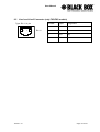
1
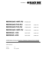
User Manual
MDS932AE-10BT-R2
STANDALONE
MDS932AE-FXO-R2
STANDALONE
COMMING SOON
MDS932AE-FXS-R2
STANDALONE
COMMING SOON
MDS933AE-10BT-R2
STANDALONE
COMMING SOON
MDS932C-1-R2
RACK-CARD
COMMING SOON
MDS932C-2-R2
RACK-CARD
COMMING SOON
G.SHDSL Modem following the Restriction of Hazardous Substances Directive (RoHS)
USER MANUAL
Version
1.5
Revision
05. July 2005
User Manual
© Copyright ©2005 by BLACK BOX Network Services AG. The contents of this publication
may not be reproduced in any part or as a whole, transcribed, stored in a retrieval system,
translated into any language, or transmitted in any form or by any means, electronic,
mechanical, magnetic, optical, chemical, photocopying, manual, or otherwise, without the prior
written permission of BLACK BOX Network Services AG. All rights reserved.
Version: 1.5
Page. 2 of 28
User Manual
VERSION CONTROL.......................................................................................................... 5
1
GENERAL INFORMATION........................................................................................ 6
ORDER INFORMATION ..................................................................................................... 7
2
3
4
5
6
DESCRIPTION OF THE DEVICE .............................................................................. 8
2.1
Exterior design Stand Alone models ................................................................. 8
2.2
Exterior design rack card models.................................................................... 10
RULES OF SWITCHING.......................................................................................... 12
3.1
The standalone delivery set ............................................................................ 12
3.2
The rack-card delivery set............................................................................... 12
3.3
Connection rules ............................................................................................. 12
3.4
Communication parameters of the terminal configuration............................... 13
THE COMMAND SYSTEM ...................................................................................... 14
4.1
Basic rules....................................................................................................... 14
4.2
The main menu ............................................................................................... 14
4.3
Performance management submenu.............................................................. 15
4.4
4.3.1
Loop Status submenu ....................................................................... 15
4.3.2
Ethernet Status submenu.................................................................. 16
Configuration management submenu ............................................................. 16
4.5
4.4.1
DSL Setup ......................................................................................... 17
4.4.2
Ethernet Setup submenu................................................................... 19
4.4.3
Profile submenu ................................................................................ 20
Security management submenu ..................................................................... 20
TFTP UPLOAD ........................................................................................................ 21
5.1
Unit preparation............................................................................................... 21
5.2
PC Software download.................................................................................... 21
5.3
Unit termination ............................................................................................... 21
SNMP ....................................................................................................................... 22
6.1
Version: 1.5
Traps ............................................................................................................... 22
Page. 3 of 28
User Manual
7
TECHNICAL SPECIFICATIONS.............................................................................. 23
8
STORAGE CONDITIONS ........................................................................................ 24
9
CONNECTOR’S DESCRIPTION ............................................................................. 25
10
9.1
DSL Connector Standalone units (MDS932/933AE-10BT-R2) ....................... 25
9.2
DSL Connector for Rack-Cards (MDS932C-1/2-R2) ...................................... 25
9.3
Monitor Connector........................................................................................... 26
9.4
Hub Connector ................................................................................................ 26
9.5
Line1 and Line2 Connector (only FXO/FXS models) ...................................... 27
DESCRIPTION OF INTERFACE CABLES.............................................................. 28
10.1 Ethernet cable ................................................................................................. 28
10.2 DSL cable........................................................................................................ 28
Version: 1.5
Page. 4 of 28
User Manual
VERSION CONTROL
Version
Date
Major changes to previous version
1.0
31.12.2001
Initial version of the manual corresponding to version 1.2 of
the device microprogram
1.1
23.10.2003
New function description corresponding to software release
V1.6
Corrected Connecter description 9.1
Changed DSL cable to twisted type 10.2
1.2
26.1.2004
Manual corresponding to software version 1.7
Implementation of SRL models
1.3
11.2.2005
Manual corresponding to software version 1.9s
SNMP topic implemnted
TFTP topic implemented
Small Text changes
1.4
13.06.2005
New design of PCB which is following the Restriction of
Hazardous Substances Directive (RoHS)
One Ethernet connector instead of two
Manual corresponding to software version 2.2/2.3
1.5
05.07.2005
Added Connecter drawing 8.2
Small Text changes
Version: 1.5
Page. 5 of 28
User Manual
1 GENERAL INFORMATION
•
High-speed symmetrical data transmission over one physical copper
twisted pair with the 135 Ohm impedance according to ETSI TS 101 135.
•
ITU-T G.991.2 (G.shdsl) line encoding.
•
Line rate in the range from 72 Kbit/s to 2320 Kbit/s.
Line rate in the range from 144 Kbit/s to 4624 Kbit/s (4W models only)
•
Manual or automatic mode of line-speed adjustment.
•
Ethernet 10/100Base-T interface, Full/Half duplex.
•
Transmition of VLAN packet (IEEE-802.1Q).
•
Dynamic table formation of MAC addresses.
•
Accumulation of up to 1024 MAC addresses.
•
Granting of 95% of the digital channel band to the user.
•
In-built functions of diagnostics and self-testing.
•
Low power consumption, easy-to-use applications.
•
Console port for the local management.
•
Telnet port for the local / remote management
•
SNMP Management
•
Remote TFTP Software upload
•
230 Vac power
For MDS932AE-FXO/FXS-R2
•
up to 2 voice cannel.
Version: 1.5
Page. 6 of 28
User Manual
ORDER INFORMATION
MDS932AE-10BT-R2
Standalone Modem, G.shdsl, 10/100Base-T Bridge, VLAN,
Adapter 230 Vac
MDS932C-1-R2
Rackcard Modem, G.shdsl, 10/100Base-T Bridge, VLAN
MDS932C-2-R2
Rackcard Dual Modem, G.shdsl, 10/100Base-T Bridge, VLAN
MDS933AE-10BT-R2
Standalone Modem, G.shdsl, 1 or 2 pairs, up to 4.6Mbps,
10/100Base-T Bridge, VLAN, Adapter 230 Vac
MDS932AE-FXS-R2
Standalone Modem, G.shdsl, 10/100Base-T Bridge, VLAN,
Adapter 230 Vac, with 2 FXS interfaces
MDS932AE-FXO-R2
Standalone Modem, G.shdsl, 10/100Base-T Bridge, VLAN,
Adapter 230 Vac, with 2 FXO interfaces
Version: 1.5
Page. 7 of 28
User Manual
2 DESCRIPTION OF THE DEVICE
2.1
Exterior design Stand Alone models
The front panel of the device has 3 LEDs (FXO and FXS has 2 additional LEDs):
Status
informs the user about the status of the local device. The following four statuses are
possible
«blinking red»
informs the user about malfunctioning of the modem’s hardware
and software. In this case, the modem is out of order and should be
submitted to the service center for being repaired.
«red»
informs the user about an urgent alarm. An abruption of the
connection, the correspondence of the signal-to-noise ratio which
does not allow to transmit information and a great number of
errored blocks can cause an urgent alarm. See the “Command
menu” chapter for detail.
«amber»
informs the user about non-urgent alarms. An abruption of
connection over the user’s interface can cause non-urgent alarms.
«green»
absence of alarms. Normal functioning of the device.
WAN
informs the user about the status of the remote device. At the time being the remote
configuring of modems is not provided.
LAN
The LED is lit upon an incorrect connection to the LAN. The LED is blink upon the
detection of packets in the segment of the current LAN.
PORT1
Informs the user about FXO/FXS activity on port 1
PORT2
Informs the user about FXO/FXS activity on port 2
Version: 1.5
Page. 8 of 28
User Manual
The back panel of the MDS932AE-10BT-R2 and MDS933AE-10BT-R2 modem has:
•
The “12V” power connector. The connection of the modem to the 230 V power supply
is implemented using an external power supply unit;
•
the “DSL” connector to connect the modem to the leased physical line.
•
the “Monitor” connector to control the modem and store statistics;
•
“HUB” connectors to connect the modem to a HUB using a straight Patch Cord
The back panel of the MDS932AE -FXO/FXS-R2 modem has additionally:
•
The “PORT1” and ”PORT2” connector to connect to PABX (FXO model) or to telephone
(FXS model).
Version: 1.5
Page. 9 of 28
User Manual
2.2
Exterior design rack card models
Version: 1.5
Page. 10 of 28
User Manual
Status(L)
informs the user about the status of the local device. The following four statuses are
possible
«blinking red»
informs the user about malfunctioning of the modem’s hardware and
software. In this case, the modem is out of order and should be
submitted to the service center for being repaired.
«red»
informs the user about an urgent alarm. An abruption of the
connection, the correspondence of the signal-to-noise ratio which
does not allow to transmit information and a great number of errored
blocks can cause an urgent alarm.
«amber»
informs the user about non-urgent alarms. An abruption of
connection over the user’s interface can cause non-urgent alarms.
«green»
absence of alarms. Normal functioning of the device.
Status(R)
informs the user about the status of the remote device. At the time being the remote
configuring of modems is not provided.
Ethernet
The LED is lit upon an incorrect connection to the LAN. The LED is blink upon the
detection of packets in the segment of the current LAN.
Version: 1.5
Page. 11 of 28
User Manual
3 RULES OF SWITCHING
3.1
The standalone delivery set
The delivery set includes:
•
the subscriber access device (a modem)
•
the power supply source (an AC adapter)
•
the cables for the line connections
3.2
The rack-card delivery set
The delivery set includes
•
the subscriber access device (a modul)
•
the cables for the line connections
3.3
Connection rules
During the connection of the modem stick to the following rules:
•
connect the modem using the “straight” Patch Cord cable to the hub
through the HUB connector.
•
connect the modem using the “crossover” Patch Cord cable to the PC
through the HUB connector.
•
connect the modem, if necessary, to the serial port of the PC through
the “MONITOR” connector using the “straight” modem cable;
•
connect the modem to the line using the “DSL” connector;
•
connect the power supply unit to the AC power system;
•
connect the modem to the power adapter using the “AC 12V” connector; it’s necessary to
use 13.5V adapter for FXS models
•
launch the hyper-terminal operation program on the PC.
Version: 1.5
Page. 12 of 28
User Manual
3.4
Communication parameters of the terminal configuration
It is necessary to set the following parameters to monitor the modem:
•
transmission rate – 9600;
•
data bits – 8;
•
parity – none;
•
number of stop bits – 1;
•
flow control – None
To update the information on the screen use the “Enter” key. The following menu will appear
on the screen.
Input Password:
Please enter your programmed password. The unit will be delivered with the default password
“admin”
After entering the password the following menu will appear.
Discovery G.SHDSL
Ethernet Monitor V2.3
+-----------------------+
+
Main Menu
+
+-----------------------+
1. Performance management (PM)
3. Configuration management (CM)
4. Security management (SM)
5. Exit Console
Select item number or ESC to Upper level menu>>
The modem is ready to be configured.
Version: 1.5
Page. 13 of 28
User Manual
4 THE COMMAND SYSTEM
4.1
Basic rules
After the command is typed, press <enter>.
The <Backspace> key is used to edit commands.
It is necessary to input item number, for choising menu item,
You can use “PageUP”, “PageDown” and “Space” keys, for scrolling list of available value of
parameters,
The “Esc” key is using for canneling of new value of parameters or reterning to up menu
screen.
4.2
The main menu
The main menu is the following:
Discovery G.SHDSL
Ethernet Monitor V2.3
+-----------------------+
+
Main Menu
+
+-----------------------+
1. Performance management (PM)
3. Configuration management (CM)
4. Security management (SM)
5. Exit Console
Select item number or ESC to Upper level menu>>
The menu consists of five submenus. To choose the needed submenu, it is necessary to type
its number and press “Enter”. The main menu also contains information about the current
version of the firmware. It is important that you inform the service center about it when being
consulted.
Version: 1.5
Page. 14 of 28
User Manual
4.3
Performance management submenu
Upon activation of the performance management submenu the following message will be
displayed.
Performance Management
1.Loop Status...
4.EtherNet Status...
Select item number or ESC to Upper level menu>>
4.3.1 Loop Status submenu
Upon activation of the performance management submenu the following message will be
displayed.
Performance Management->Loop Status
System Up Time: 0 Day 00:16:31
= Loop 1 =
Loop Up Time:
0 Day 00:15:07
Operation State:Data
Line Speed:
2312K
Rx Gain:
5.43 dB
Tx Power:
14.50 dBm
S/N Ratio:
37.74 dB
Framer Status: In sync.
Loop Atten.:
-0.19 dB
Operation Mode: Slave
Auto/Fixed:
Auto
Clock Source:
Follow Loop
Annex:
A/B
Max. Speed:
2312K(36N)
Min. Speed:
72k(1N)
1.Disconnect
Select item number or ESC to Upper level menu>>
Version: 1.5
Page. 15 of 28
User Manual
4.3.2 Ethernet Status submenu
Upon activation of the performance management submenu the following message will be
displayed.
Performance Management->EtherNet Status
Link:Link down
Used Entries:0
Fwd Packets:0
Speed:Auto
Link Speed:---Tx Packets:0
Drop Packets:0
Duplex:Auto
Link Duplex:---Rx Packets:0
MAC Address: 00-00-00-00-00-00
1.Clear Counters
Select item number or ESC to Upper level menu>>
4.4
Configuration management submenu
Upon activation of the configuration management submenu the following message will be
displayed.
Configuration Management
1.DSL Setup...
4.EtherNet Setup...
6.Profile...
Select item number or ESC to Upper level menu>>
Version: 1.5
Page. 16 of 28
User Manual
4.4.1 DSL Setup
In this menu you can setup the DSL link. When you have selected that menu, the following will
appear:
Configuration Management->DSL Setup
1.[Loop 1 Operation Mode]:Slave
2.[Loop 1 Auto/Fixed]:Auto
4.[Loop 1 Min. Connection Speed]:72K(1N)
5.[Loop 1 Max. Connection Speed]:2312K(36N)
6.[Loop 1 Annex]:B
7.[Loop 1 Tx Level Adjustment]:0 dB
18.[2W/4W]:2W
Select item number or ESC to Upper level menu>>
4.4.1.1 Operation Mode
In this menu you can setup the unit to one of the following states:
Master, Slave
4.4.1.2 Auto / Fixed
This Menu is NOT available if the unit is in 4W mode!
In this Mneu you can setup the unit to one of the following states:
Auto, Fixed
If Auto is selected, the unit works in the adaptive mode.
If Fixed is selected, the unit works with fixed linerates.
4.4.1.3 Min- Max Connection Speed (only if Auto is selected)
•
In the Min. Max Connection Speed menu, you can specifiy your desired Adaptive mode
speed limit borders in the range of 72 kbps to 2312 kbps for 2wire units and 144 kbps to
4624 kbps for 4wire models
Version: 1.5
Page. 17 of 28
User Manual
4.4.1.4 Fixed Connection Speed (only if Fixed is selected)
•
In the Fixed Connection Speed menu, you can specifiy your desired speed in the range of
72 kbps to 2312 kbps for 2wire units and 144 kbps to 4624 kbps for 4wire models
4.4.1.5 Annex
•
With the Appendix menu you can choose between A, B, A / B. If you don’t know what
Annex you have to setup, then use the A / B configuration.
4.4.1.6 Tx Level Adjustement
•
In the Tx Level Adjustements menu you can setup you desired TX output level in the range
from +2dB to –13dB.
Please note: changing the default value of 0 to another value may cause serious
malfunction of the DSL line. It should be changed only by qualified personal.
4.4.1.7 2W / 2CH / 4W
•
In the 2W / 4W (2wire / 4 wire) Adjustements menu you can setup you desired number and
mode of the DSL line. The following modes are possible:
2W:
1 DSL line, normal mode
4W:
2 DSL lines, dual pair mode (4W models only)
2CH:
2 DSL lines, multipoint mode (4W models only)
Version: 1.5
Page. 18 of 28
User Manual
4.4.2 Ethernet Setup submenu
Configuration Management->EtherNet Setup
1.[Speed]:Auto
2.[Duplex Mode]:Auto
3.[Disable Mac Filter]:No
4.IP Address>>192.168.5.105
5.Subnet Mask>>255.255.255.0
6.Gateway Address>>192.168.5.1
7.NMS IP Address>>192.168.5.254
8.Read Community>>
9.Write Community>>
10.Trap Community>>
11.TFTP Server>>Off
Select item number or ESC to Upper level menu>>
•
•
In the Speed menu, you can setup the Ethernet speed to the following states:
10M, 100M or Auto
In the Duplex Mode menu you can setup the Ethernet ports to the following states:
Half, Full or Auto
•
In the IP Adress-, Subnet Mask- and Gateway Address menu you, can setup the desired Ip
settings
•
In the NMS IP Address menu you can setup the IP receiver address for the SNMP traps
(the Network Manager).
•
In the Read / Write / Trap Community menu you can setup the desired SNMP community
address names (text).
•
TFTP Server
Version: 1.5
Page. 19 of 28
User Manual
4.4.3 Profile submenu
Users can save and load up to 4 profiles for different tasks. The Profile 0 is the default profile
during power on. Users have to save all new value of parameters before power off.
4.5
Security management submenu
The security management is using for setting the desired password for the console access.
Version: 1.5
Page. 20 of 28
User Manual
5 TFTP UPLOAD
5.1
Unit preparation
• Enter the Ethernet Setup submenu.
• Enter menu point 11 and switch TFTP on
• Exit menu point 11
• Enter the Profile Submenu and Save the settings to Profile 0
• Restart the unit
5.2
PC Software download
• Unzip the download file to an empty directory
• Open the cmd.exe windows menu (Run, cmd)
• Enter the directory with the unzipped files
• Enter the following command “upload ´ipadress´”
• Wait until the program terminates
• Close the cmd.exe windows menu
5.3
Unit termination
• Enter the Ethernet Setup submenu.
• Enter menu point 11 and switch TFTP off
• Exit menu point 11
• Enter the Profile Submenu and Save the settings to Profile 0
• Restart the unit
Version: 1.5
Page. 21 of 28
User Manual
6 SNMP
6.1
Traps
The unit supports the following traps:
Trap
Description
Cold start
Sent on unit startup
Linkup
Sent on DSL link up
Linkdown
Sent on DSL link loss
Authorization Error
Sent on reception of a wrong cummunity string (hacker attack)
Version: 1.5
Page. 22 of 28
User Manual
7 TECHNICAL SPECIFICATIONS
The main technical specifications of modems of the Black Box family are presented below in
the table.
Line interface.
Standard
ETSI 101 135
Regulation
RoHS ready (Pb-free)
Number of pairs
1 or 2
Line rate
2 wire models
72 – 2320 Kbit/s
4 wire models
144 – 4624 Kbit/s
Communication range for cables with
the wire diameter of
0.4 mm:
0.9 mm:
approx:
aprrox:
144 Kbit/s
8.2 km
31 km
2320 Kbit/s
3.6 km
13.7 km
(values are depending on noise
enviroment and line quality)
Line code
G.shdsl (TC-PAM)
Input impedance of the physical line
135 Ohm
Output signal level
0.5dBm – 15.5 dBm
Transmission spectrum
from 0…450 kHz
User’s interface
Standard:
IEEE-802.3
IEE-802.1Q
Interface type:
Ethernet 10/100Base-T, Full/Half Duplex
Connector:
RJ-45
Management
Monitoring
VT100
Power supply
Supply voltage:
~230 Vac ± 10%; 50 Hz
Power consumption:
No more than 5 W
Grounding resistance
No more than 10 Ohm
Protection
Conforms to the requirements of the GOST (State
Standard) 12.2007.0-85, GOST 7153-85,
GOST Р.50033-92 and Norm 9-93
Climatic conditions
Storage Temperature range
-30° C … +75° C
Operating Temperature range
-50° C … +75° C
Relative humidity of air
5%…85%
Version: 1.5
Page. 23 of 28
User Manual
8 STORAGE CONDITIONS
The equipment of the Black Box family while being packed should withstand all means of
transport at a temperature in the range form -50о С to +75о С and the relative humidity of air up
to 100% at 25о С. The equipment can also withstand air-transport at a low air pressure of 12
kPa (90 Torr) at -50о С.
The packed equipment of the Black Box family can be stored within 12 months (from the date
of transshipment including transporting time) in storage rooms without heating
at -50о С - +75о С and the mean monthly value of the air humidity of 80%
at 20о С; short-term increases of air humidity up to 98% (no more than a month a year) at a
temperature not exceeding 25о С without moisture condensation is admissible.
The equipment should be stored in storage buildings, which protect the devices from
atmospheric precipitations. The equipment should be kept on shelves or in factory packages in
the absence of vapors of acids, alkali and other atmospheric impurities.
Version: 1.5
Page. 24 of 28
User Manual
9 CONNECTOR’S DESCRIPTION
9.1
DSL Connector Standalone units (MDS932/933AE-10BT-R2)
Type: RJ-45, 8 pin
1
9.2
8
RJ-45
Number
Signal
Assignment
1,2
NC
-
3
LB,a
Ttp (4W model only)
4
LA,a
tip
5
LA,b
ring
6
LB,b
ring (4W model only)
7,8
NC
-
DSL Connector for Rack-Cards (MDS932C-1/2-R2)
Type: RJ-45, 8 pin
1
Version: 1.5
8
RJ-45
Number
Signal
Assignment
1
LB,a
tip (4W model only)-
2
LB,b
ring (4W model only)
3
NC
-
4
LA,a
tip
5
LA,b
ring
6,7,8
NC
-
Page. 25 of 28
User Manual
9.3
Monitor Connector
Type: Sub-D9, female
1
6
DB9
9
5
female
9.4
Number
Signal
Assignment
1
NC
-
2
TXD
Transmit data
3
RXD
Receive data
4
DTR
Data terminal ready
5
SGND
Signal ground
6
NC
-
7
NC
-
8
NC
-
9
NC
-
Hub Connector
Type: RJ-45
1
Version: 1.5
8
RJ-45
Number
HUB assignment
1
Rx+
2
Rx-
3
Tx+
4
NC
5
NC
6
Tx-
7
NC
8
NC
Page. 26 of 28
User Manual
9.5
Line1 and Line2 Connector (only FXO/FXS models)
Type: RJ-11, 4 pin
1
Version: 1.5
4
RJ-11
Number
Signal
Assignment
1
NC
-
2
LA,a
tip
3
LA,b
ring
4
NC
-
Page. 27 of 28
User Manual
10 DESCRIPTION OF INTERFACE CABLES
10.1 Ethernet cable
Side А
Color of wire
Side B
1
white/green
1
2
green/white
2
3
white/orange
3
4
blue/white
4
5
white/blue
5
6
orange/white
6
7
white/brown.
7
8
brown/white
8
Side А
Color of wire
Side B
1
white/green
1
2
green/white
2
3
white/orange
3
4
blue/white
4
5
white/blue
5
6
orange/white
6
7
white/brown.
7
8
brown/white
8
10.2 DSL cable
Version: 1.5
Page. 28 of 28