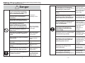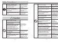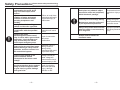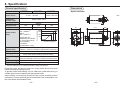
1
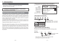
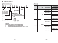
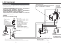
Instruction Manual
Speed Controller for Small Geared Motors
MGSD Series
• Thank you for purchasing the Panasonic speed controller
MGSD for small geared motor.
• Carefully read this manual thoroughly before installing and
operating the product.
Section "Safety Precautions" (pp. 3-9) contains very important
information concerning safety and reliable operation.
Keep this manual in a safe location where it can be easily
accessed for reference.
The user and operator should always refer to this manual.
● This
product is for industrial equipment. Don't use this product at general household.
Safety Precautions Please observe safety precautions fully.
• Contents
page
Safety Precautions .......................................................... 3
1. Introduction ............................................................... 10
Unpacking ............................................................................. 10
General description of the speed controller ......................... 10
2. Names and functions ................................................ 14
3. Installation ................................................................. 15
4. Wiring diagram .......................................................... 17
Considerations for wiring ....................................................... 17
Wiring diagram ..................................................................... 18
Standard electrical wiring diagram ....................................... 20
Speed change only .......................................................... 20
Unidirectional rotation and electric brake ......................... 22
Normal/reverse rotation and electric brake ...................... 24
Peripheral wiring .................................................................... 26
Motor wiring with cooling fan motor (F) or thermal protector (TP) .... 26
Wiring to electromagnetic brake ....................................... 27
5. Options ....................................................................... 28
6. References ................................................................. 32
7. Compatible with international standards ................ 38
8. Specification .............................................................. 42
9. Inspection and maintenance .................................... 44
Inspection ............................................................................. 44
Troubleshooting .................................................................... 45
Various icons and important messages are used in this
manual to avoid problems that could result in hazards to
personnel and damage to properties.
• The below explains what will happen if someone fails to
heed a particular precaution statement.
Danger
Danger statements are used to
indicate hazards or unsafe
practices witch COULD result
in severe personal injury or
death.
Caution
Caution statements are used
to indicate hazards or unsafe
practices which COULD result
in minor personal injury or
product or property damage.
• The following symbols are used to describe the type of
Do and Don't.
This symbol is used to indicate a practice
that shall not be attempted.
This symbol is used to indicate a practice
that shall be done.
10. After-Sale Service (Repair) ..................................... 46
–2–
–3–
Safety Precautions Please observe safety precautions fully.
Use overcurrent protection device,
ground-fault circuit interrupter,
overtemperature protecting device,
and emergency stop device.
Danger
Don't use the speed controller in
or near environment containing
water, corrosive gas, flammable
gas or flammable material.
Don't place flammable materials
near the motor (including the
controller).
After an earthquake, first verify
safety.
To prevent
possibility of fire.
Don't make soldering joint on a
round pin of the speed controller.
Don't damage leadwires or
subject leadwires to excessive
stress such as strong pressure,
heavy object and clamping load.
Failure to heed
these requirements
will result in electric
shock, personal
injury or fire.
Before transferring, wiring or
checking product, disconnect the
power source for safe isolation.
Incomplete power
disconnection will
cause electric shock.
Securely install the equipment to
prevent bodily injury or fire in
case of earthquake.
Failure to heed
these requirements
will result in electric
shock, personal
injury, fire,
malfunction or
damage.
Will cause electric
shock, malfunction
or damage.
Provide emergency stop circuit
externally for instantaneous
interruption of operation and
power supply.
Don't use the controller in a place
subject to excessive vibration or
shock.
Will cause electric
shock, personal
injury or fire.
Install the unit to a nonflammable
construction (e.g. metal).
Installation on a
flammable material
may cause fire.
Don't remove the speed controller
setting knob.
Will cause burn
injury or electric
shock.
Don't touch rotating member of
the motor.
Will cause personal
injury.
Installation area should be free
from excessive dust, and from
splashing water and oil.
Failure to heed this
precaution will result
in electric shock,
personal injury, fire,
malfunction or
damage.
Don't touch potentially hot motor
casing.
Will cause burn
injury.
Don't attempt to carry out wiring or
manual operation with wet hand.
Will cause electric
shock, personal
injury or fire.
Correctly run wirings to the
tacho-generator.
Incorrect wiring will
result in short circuit,
electric shock,
personal injury, etc.
Wiring work should be done by a
qualified electrician.
Wiring work done by
an inexperienced
person will cause
electric shock.
Turn off power upon power
interruption or activation of
overtemperature protecting device.
Unpredictable
restarting will cause
personal injury.
Don't use leadwires soaked in
water or oil.
–4–
–5–
Safety Precautions Please observe safety precautions fully.
Don't lock the motor shaft while
the motor is running.
Install the equipment in the
control board and keep the
terminal block and protect it from
inadvertent contact.
Failure to heed this
precaution will result in
electric shock, personal
injury, fire, malfunction
or damage.
After correctly connecting
leadwires, insulate the live parts
with insulator.
Incorrect wiring will
result in short circuit,
electric shock, fire or
malfunction.
Don't turn off and on power so
frequently.
Ground the motor ground to the
earth.
Floating ground
circuit will cause
electric shock.
Don't pull leadwires with an
excessive force.
Don't clog or put an object into
the radiating hole of the motor.
Don't use the equipment in highly
intensive electric field.
Caution
Don't move the product by
holding leadwires or motor shaft.
Don't put the machine into
unstable operation.
Once power failure occurs, don't
come close to the machine that
will unexpectedly start upon
recovery of the power.
Provide secure mechanism so
that the restarting of the machine
will not cause personal injury.
Don't apply excessive shock to
the motor shaft.
Don't apply excessive shock to
the product.
Don't get on the product. Don't
place heavy object on the
product.
–6–
Failure to heed
these precautions
will cause bodily
injury.
Locked motor will
cause fire, electric
shock, or malfunction.
Failure to heed this
instruction will result
in fire.
Failure to heed this
instruction will result in
fire, personal injury,
malfunction or damage.
Failure to heed this
instruction will cause
fire, electric shock or
personal injury.
Don't use the equipment under
direct sunshine.
Failure to heed
these instructions
will cause personal
injury or fire.
Don't use the equipment in an
environment where electrostatic
voltage potentials may be
produced.
Induced malfunction
will cause
malfunction or
personal injury.
Don't drop or cause topple over
of something during
transportation or installation.
Failure to heed this
instruction will result
in personal injury or
malfunction.
Failure to heed this
instruction will cause
fire, electric shock or
malfunction.
Failure to heed this
instruction will result in
electric shock, personal
injury, fire, malfunction
or damage.
Don't use a variable transformer
or transformer having capacity
insufficient to feed the load.
Excessive shock will
cause failure.
Don't use the equipment outside
the limits described on the
nameplate and user's manual.
Failure to heed this
instruction will result in
electric shock, personal
injury, fire, malfunction
or damage.
Never attempt to perform
modification, dismantle or repair.
–7–
Failure to heed this
instruction will cause
fire, electric shock or
personal injury.
Safety Precautions Please observe safety precautions fully.
Perform installation by taking into
consideration the mass of the
body and rated output of the
product.
Adjust ambient environmental
condition of motor and speed
controller to match the motor
operating temperature and
humidity.
Failure to heed these
instructions will result
in personal injury or
malfunction.
Exactly follow the installing
method and direction specified.
Use the speed controller in
combination with the specified
motor.
Failure to heed this
instruction will result
in fire.
Connect the motor
electromagnetic brake control
relay in series with a ground-fault
interrupter, circuit breaker and
relay so that they turn off the
circuit upon emergency stop.
Lack of connection
will cause
malfunction.
Test-run the securely fixed motor
without loading to verify normal
operation, and then connect it to
the mechanical system.
Operation using a
wrong model or
wrong wiring
connection will result
in personal injury.
Level of input voltage to the
speed controller should
correspond to the motor rated
voltage.
Operation from a
voltage outside the
rated voltage will
cause electric shock,
personal injury or fire.
Provide protection device against
idling of electro-magnetic brake
or gear head, or grease leakage
from gear head.
Lack of protection
will cause personal
injury, damage,
pollution or fire.
–8–
Don't place any obstacle object
around the motor and peripheral,
which blocks air passage.
Temperature rise will
cause burn injury or
fire.
Correctly run and arrange wiring.
Maintenance must be performed
by an experienced personnel.
Wrong wiring will
cause personal injury
or electric shock.
Always keep power disconnected
when the power is not necessary
for a long time.
Improper operation
will cause personal
injury.
Scraps must be treated as
industrial waste.
–9–
1. Introduction
Unpacking
Designation and rating on the nameplate
· Verify that the model No. matches your order sheet.
· Damage in transit is not found.
Should you find any discrepancy in the product,
consult your local dealer.
General description of the speed controller
The MGSD type speed controller is designed to operate with a small
geared motor to adjust and vary its speed. The speed is adjusted from
the speed setting knob. The input voltage can be single-phase 100-120
VAC, or single-phase 200 – 240 VAC. The speed controller is compatible
with EC directive and UL standard.
Compatible with DIN terminal block which is convenient to install on the
distribution board, and small timer common option available from
Panasonic Electric Works Co.,Ltd. (pp. 32 – 37).
Rated
input voltage
Input current
Rated speed
Rated output
Serial No.
(production No.)
Input
Input Current
Rated Speed
Rated Output
Model
name
50/60Hz 1Ph 200–240V
1.0A
1400/1700min–1
6–90W
Ser.No. 06110001G
Panasonic Corporation
Made in China
C58401
Description of model No.
M G S D B 2
1–4
5
Series
Output
100V
Read this manual thoroughly so that you will become gradually
acquainted with the excellent features of your speed controller for small
geared motor and understand how to fully utilize these functions. The
speed controller is designed to be integrated into a general control board.
The product must be handled by experienced personnel familiar with
the product.
SPEED CONTROLLER
MGSDB2
Model No.
200V
A : 3 – 40W
B : 60 – 90W
B : 6 – 90W
6
Input power supply
1. Single phase 100 – 120 VAC
2. Single phase 200 – 240 VAC
Serial number (production No.)
The Ser. No. on the nameplate contains the following codes.
Example
Ser.No. * 06
11
0001 *
Sequential number
Manufacturing month
Manufacturing year
This product was manufactured in November 2006
and assigned a sequential number 0001.
– 10 –
– 11 –
1. Introduction
Motor Part Number
Rating
M 9 1 Z 9 0 G V 4 L G
1,2
3
4
5,6
7
Output
Size
M6: Sq.60mm
M7: Sq.70mm
M8: Sq. 80mm
M9: Sq. 90mm
Series
1 : Induction motor
R : Reversible motor
Series
X : 40 W or lower
Z : 60 W or higher
8
9
10
11
Model No.
Output
Power
supply
Compatible
induction motor
No. of
poles
M61X***V4**
Shape of shaft
G : Pinion
S : Round
Variable speed
V : Variable (without brake)
BV: Variable with electromagnetic
brake
Voltage
L : 100V
D : 110 – 115V
Y : 200V
G : 220 – 230V
Version
Blank : Pinion shaft motor (Japanese standard)
S
: Round shaft motor (Japanese standard)
G
: International standard approved motor (CE, UL, CCC)
MGSDA1 3-40W
AC100V
to
AC120V
M71X***V4**
M81X***V4**
M91X***V4**
M91Z***V4**
MGSDB1 60-90W
M61X***V4**
AC200V
MGSDB2 6-90W
M71X***V4**
to
AC240V
M81X***V4**
M91X***V4**
M91Z***V4**
– 12 –
– 13 –
Compatible
reversible motor
Compatible reversible motor
with electromagnetic brake
M6RX***V4**
M6RX**GBV4**
M7RX***V4**
M7RX**GBV4**
M8RX***V4**
M8RX**GBV4**
M9RX***V4**
M9RX**GBV4**
M9RZ***V4**
M6RX***V4**
M6RX**GBV4**
M7RX***V4**
M7RX**GBV4**
M8RX***V4**
M8RX**GBV4**
M9RX***V4**
M9RX**GBV4**
M9RZ***V4**
2. Names and functions
Terminal block locking
hook mounting hole
3. Installation
Terminal block
locking claw
Nameplate
Installation location
(1) Indoors free from rain and direct sunlight: the product is not of a
waterproof construction.
(2) Free from vibration 4.9 m/s2 or more; shock, dust, iron powder or oil
mist; splash of water, oil and grinding fluid; and away from flammable
materials, corrosive gas (H2S, SO2, NO2, Cl2, etc.) or flammable gas.
(3) Well ventilated dry and clean location containing negligible amount
of oil or dust.
Environmental condition
Caution plate
Speed control knob
<Rear panel>
Item
Condition
Operating temperature
–10 – 50°C
Storage temperature
–20˚C – 60˚C
Operating humidity
90% RH or below (no dewing)
Allowable vibration
4.9 m/s2 or below (10 – 60 Hz)
Altitude
1000 m max.
Pin
Pin number
Terminal block
locking claw
– 14 –
– 15 –
3. Installation
4. Wiring diagram
Considerations for wiring
Installing method
The product can be mounted in either of the following two ways but
must be installed inside the control board.
Orientation of the product in the control board is not limited.
• Using flush mounting frame
(sold separately: see p. 34)
• Using miniature DIN terminal block
(sold deparately: see pp. 32 and 33)
Terminal block
Flush mounting frame
DIN rail
Mounting plate
<Precautions>
For further information,
consult the manufacturer
of terminal block.
Caution
Special care is always given to our products during manufacturing and
delivery to keep quality from deteriorating. Customer is also required to
keep the quality by designing and providing failsafe and safety operating
field and condition so that external noise, electrostatic charge, wrong
wiring, wrong parts are prevented or eliminated.
In rare instances, the product may give off fume like a smoke of a
cigarette if it is in a specific malfunctioning state. Precaution against
possible fumes should be taken into consideration when the product is
used in a clean room, etc.
DON'T
• Use a terminal block or socket for connection. Do not solder the lead
to the pin.
• When using a transformer or variable transformer, its capacity must
be larger than the rated current of the product by the factor of 2 or
more, to assure reliable operation.
• If the input lead is longer than 1 m (e.g. lead from a tachometer
generator), seal it or replace it with shielded cable to prevent induction
of noises.
Don't turn the shaft of speed
control potentiometer using a
tool with the knob removed.
– 16 –
• Don't ground the shielding.
• The length of the wiring between the speed controller and the motor
should be 3 m or shorter.
• Wiring from the tachometer generator (TG) carries current at a high
voltage: Risk of electrical shock.
• When using a cooling fan motor or a motor with thermal protector,
also see p. 26.
High voltage is
applied to the
potentiometer:
Danger!
– 17 –
4. Wiring diagram
Wiring diagram
Speed control knob
• The motor speed can be adjusted from the speed setting knob on the
controller front panel.
• The thick continuous lines represent main circuit. Use conductor of
size 0.75 mm2 (AWG 18) or larger for the main line.
• The thin continuous lines represent signal circuit. Use conductor of
size 0.3 mm2 (AWG 22) or larger in the signal circuit.
When the distance from the tachometer generator (TG) is long, use
shielded twisted pair cable.
This knob adjusts the rotating speed of the motor from
90 (min-1) to 1400/1700(min-1) at 50/60 Hz.
Miniature DIN
terminal block
Panasonic Electric
Works Co.,Ltd.
AT7803
See Section 6.
References.
65
4
3
<Caution>
Do not ground the shielding material.
Circuit breaker
(NFB)
Power supply
100 V system: 1ø100 – 120 V
200 V system: 1ø200 – 240 V
<Caution>
<Precautions>
Install ground-fault
circuit interrupter in
the power supply.
The input voltage must be in
the range of rated voltage
compatible with the motor
specification.
Install a noise filter and surge
absorber to protect against
external noise and lightning surge.
Noise filter
Surge absorber
(option)
7 8 1 2
TG
White
Gray
Black
Pink
Pink
Capacitor cap
Motor
Capacitor
(supplied with the motor)
Power switch
Ground the return circuit to the earth terminal.
Should be class D earthing (100 or less, ø1.6 mm or more).
– 18 –
Ground the return circuit to the earth
terminal.
Should be class D earthing (100 or less,
ø1.6 mm or more).
Tightening torque: 1.0 – 1.5 N·m
– 19 –
For wiring connection of
the capacitor, see the
motor instruction manual.
4. Wiring diagram
Standard electrical wiring diagram
Normal/reverse rotation
SW1
Speed change only
2
1
SW1
2
1
Feed motor
rated voltage
Speed controller
CW
White
8
Gray
7
Motor
Black
Speed controller
Unidirectional rotation
Spark killer
R1 C1
White
8
7
CW
3
CCW
6
4
3
Feed motor
rated voltage
Gray
SW2
Motor
Black
Capacitor
R1 C1
Spark killer
Pink
TG
Pink
5
6
Capacitor
Pink
4
TG
Pin No.
Pink
5
SW1
100 V supply system 5 A or more at 125 VAC
SW2
200 V supply system 5 A or more at 250 VAC
Spark killer R1+C1
DV0P008 (option)
For optional accessories, see p. 30.
<Precautions>
Pin No.
Run
SW1
ON
Stop
OFF
<Note>
Rotating direction viewed
from shaft end
CW
Clockwise
CCW
Counterclockwise
This wiring diagram causes the motor to
rotate clockwise when viewed from the motor
shaft end.
To run the motor counterclockwise,
interchange the connecting point of black
and gray leads.
– 20 –
Normal
When using independent relay
contacts for SW2 to change over
normal/reverse, interlock both
contacts so that they will not
close simultaneously.
SW1
SW2
* • To change rotation direction of
induction motor
ON
CW
Stop Reverse
OFF
ON
*
CCW
SW1: Power switch
SW2: Normal/Reverse selector
switch
Provide a motor halt period. Switch over SW2 after complete stop of the motor.
• To change rotation direction of reversible motor
A motor halt period is not necessary. Switch over SW2 while keeping SW1 turned
ON. When configuring SW2 with relay contacts, use a relay having large gap
between contacts (e.g. HG/HP relay from Panasonic Electric Works Co.,Ltd.)
to prevent malfunction due to short-circuited capacitor.
– 21 –
4. Wiring diagram
Unidirectional rotation and electric brake
40 W or higher
SW1
<Precautions>
2
1
• The number of start/stop operations should be 6/min. or less.
Feed motor
rated voltage
25 W or less
2
1
Feed motor
rated voltage
CW
Speed controller
White
Gray
7
8
3
6
4
Spark killer
RUN
SW2
Black
C1
Motor
STOP SW3
RUN
R2
Capacitor
External
braking
resistor
Pink
8
RUN
SW2
Pink TG
CW
Gray
Black
C1
Motor
R1
Capacitor
Spark killer
3
STOP
SW3
Pink
Pin No.
<Note>
This wiring diagram causes the motor to rotate clockwise when
viewed from the motor shaft end.
To run the motor counterclockwise, interchange the connecting point
of black and
SW1 100 V supply system 5 A or more at 125 VAC
gray leads.
SW2
200 V supply system 5 A or more at 250 VAC
SW3
10 mA at 10 VDC
Spark killer R1+C1
DV0P008 (option)
External braking resistor R2
DV0P003 (option)
Pin No.
Braking
When SW2 and SW3 are
switched from RUN to
STOP, electric braking is
applied for approx. 0.5 sec.,
and the motor stops
instantly.
Difference in switching time
between SW2 and SW3
must be 0.1 sec. or smaller.
Run
SW1
SW2
SW3
Stop
TG
Braking
Run
ON
RUN
STOP
RUN
SW1: Power switch
SW2: RUN/STOP switch
SW3: Braking start switch
<Precautions>
If SW2 is in RUN position while SW3 is in STOP, abnormal operation
occurs (full speed rotation for a short time; or if SW3 is in RUN
position while SW2 is in STOP, motor temperature rises excessively.
For option, refer to p. 29, 30 onward.
– 22 –
Pink
RUN
<Precautions>
5
White
7
6
4
5
R1
STOP
Speed controller
SW1
External
braking
resistor
R2
STOP
– 23 –
4. Wiring diagram
Normal/reverse rotation and electric brake
40 W or higher
<Precautions>
SW1
2
1
• The number of start/stop operations should be 6/min. or less.
External
braking
resistor
SW1
2
1
Feed motor
rated voltage
Speed controller
White
Spark killer
CW
SW4
7
8
C1
R1
SW2
RUN
3
6
4
5
STOP
STOP
SW3
RUN
CW
Black
SW5
R2
CCW
External
braking
resistor
Pink
Clockwise
CCW
Counterclockwise
SW1, SW2
100 V supply system
5 A or more at 125 VAC
SW4, SW5
200 V supply system
5 A or more at 250 VAC
SW3
DC10V 10mA
Spark killer R1+C1
DV0P008 (option)
External braking resistor R2
DV0P003 (option)
– 24 –
CCW
SW4
CW
R2 CCW
C1
SW2
CW
TG
Pink
Gray
SW5
Black
Motor
R1
Capacitor
Spark killer
7
6
4
5
White
STOP
Pink
SW3
TG
Pink
RUN
SW1
<Precautions>
When SW2 and SW3 are
switched from RUN to STOP,
electric braking is applied for
approx. 0.5 sec., and the motor
stops instantly.
Difference in switching time
between SW2 and SW3 must be
0.1 sec. or smaller.
Stop Reverse
ON
SW2
SW3
RUN
SW4
SW5
CW
0.7 sec. or longer
<Precautions>
Braking
Braking
Normal
Pin No.
CW
For option, refer to p. 29, 30 onward.
Motor
Capacitor
Rotating direction viewed
from shaft end
Pin No.
8
RUN STOP
3
Gray
CCW
Speed controller
25 W or less
Feed motor
rated voltage
STOP
RUN
CCW
SW1: Power switch
SW2: RUN/STOP switch
SW3: Braking start switch
SW4, SW5: Normal/Reverse selector
switch
If SW2 is in RUN position while SW3 is in STOP, abnormal operation
occurs (full speed rotation for a short time; or if SW3 is in RUN
position while SW2 is in STOP, motor temperature rises excessively.
<Precautions>
Never attempt to change direction (SW4, SW5) while motor is
running or electric brake is being applied.
– 25 –
4. Wiring diagram
Wiring to electromagnetic brake (40 W or below)
Motor wiring with cooling fan motor (F) or thermal protector (TP)
Speed controller
The thermal protector (TP) is an automatic reset type. To prevent hazards
caused by restarting of TP, operate it by connecting wiring as shown
below. Don't connect TP directly to the power supply.
Ry
1
2
Pin No.
Motor (M) and tachogenerator (TC) should
be connected according
to corresponding wiring
diagram (pp. 20-25).
SW A
Ry
Variable speed motor with electromagnetic brake should be wired as
shown below.
SW1
Speed controller
Peripheral wiring
Feed motor
rated voltage
2
1
C1
Pin No.
STOP
RUN
SW9
R1
Spark killer
Motor
Yellow
Brake
Yellow
Connect the
cooling fan
motor (F)
across pins
(1) and (2) on
the power
terminal.
TP
Blue or yellow
Black
M White
Gray
TP
Blue or yellow
TP
F(Black)
F(Black)
Ry Relay
F
TG
SWB
Ry
Closed
Ry
Closed
Closed Open
TP
Closed
Closed
Feed
motor
rated
voltage
Closed
ON
SW1
100V supply system
AC125V
5 A or more
SW9
200V supply system
AC250V
5 A or more
Spark killer R1+C1
TG(Pink)
SWA
SW B
ON
For option, refer to p. 30 onward.
<Precautions>
1. Operate SW9 simultaneously with RUN/STOP switching of other
switches, if any.
2. For remaining wirings, refer to corresponding wiring diagram.
ON
Run
Closed
DV0P008 (option)
Continue
Once the TP operates, cooling period is required until the operation can start.
Relay
Ry
SW A
Momentary N.O. contact
SW B
Momentary N.C. contact
100 V supply system
AC125V 5 A or more 3a contact
200 V supply system
AC125V 5 A or more 3a contact
– 26 –
– 27 –
5. Options
<Note>
Tachometer (DVOP001)
This tachometer is especially designed to operate with our speed
controller so that it can provide easier displaying of motor speed.
Unit: mm
±1
ø5
4
Speed controller
2–ø3.5 hole
Motor
48 ±0.3
TM
Pink
4
48 ±0.3
Pink TG
5
Panel cutout drawing
Calibrate the scale of the tachometer (TM) from the potentiometer on
the rear panel.
1. While running the motor at its full rotation speed without load,
adjust to 1450 min-1 if power supply is at 50 Hz, or 1750 min-1 if
60 Hz.
2. Monitor the output signal of the TG on an oscilloscope and
determine the frequency. And adjust:
rotating speed N (min-1) = 5 x f (Hz)
Caution: Since the circuit is not isolated from the power supply,
use an insulated tool such as an insulated screwdriver to protect
against electric shock.
Pin No.
External braking resistor (DVOP003)
max40
5.6 10W
ø3.8
3
12
<Precautions>
· Connect the tachometer in parallel with the tachometer generator (TG).
· If the tachometer (TM) requires longer connection cable, use shielded
twisted pair cable. Don't ground shielding of the cable.
· Accuracy of tachometer readings will depend on variation in motor
performance and operating environment (temperature and noise). The
tachometer should be used as a rough indicator.
0.5
4.8 ±0.5
(ø2.5)
(2.2)
33 ±3.0
9 +–13
Potentiometer
for calibration
14 ±1
10.5 ±1.5
48
6 ±0.5
2–M3
Mounting
screw
10.5±1.5
8.5
8 ±1
12.2
48 ±2
0.8
65
Unit: mm
48
60
Input terminal
(0.6)
<Precautions>
The resistance of DVOP003 is 5.6 . When using commercially available
resistor, choose 4.7-6.8 , 10 W or larger.
– 28 –
– 29 –
5. Options
Spark killer (DVOP008)
Surge absorber (DVOP4190)
0.1 F 120
Type R.A.V-781BWZ-4: Okaya Electric Industries Co., Ltd.
5.5 ±1
11 ±1
Unit: mm
ø4.2 ±0.2
ø0.7 ±0.05
<Circuit diagram>
UL-1015 AWG16
28 ±1
C1
+30
200 –0
The capacitance of capacitor in the DVOP008 is 0.1 F and the
resistance of the internal resistor is 120 . When using commercially
available spark killer, choose one consisting of the following parts:
R1
Unit: mm
4.5 ±0.5
<Precautions>
14.3min 17.5 ±0.5
16.5 ±1
9 ±0.5
28.5 ±1
20.5 ±0.5
R1 = 10 – 200 (1/4 W or larger)
C1 = 0.1 – 0.33 F (AC250WV)
41 ±1
Noise filter (DVOP3611-5)
Type SUP-EQ5-ER-6: Okaya Electric Industries Co., Ltd.
Unit: mm
7.0
Terminal cover (clear)
5.0
Octal pin socket (DVOP4560)
Type S-3898: Sato Parts Co., Ltd.
53.1 ±1.0
2.0
2–ø4.5
6-M4
(11.6)
(13.0)
39 ±0.1
48.4
2–ø4.5 x 6.75
8.0
6
12.0
50.0
60.0
3.2
10.0
Marking
(label)
Unit: mm
20.8
0.8
4
33
ø29
100.0 ±2.0
88.0
75.0
<Circuit diagram>
1
L
Cy
R
Cx
3
Cx
Cy
2
4
– 30 –
– 31 –
6. References
DIN rail terminal block (8-pin) (ATC180031)
Noise filter
10
49
10
27
50
40
Unit: mm
Unit: mm
24
19
Type MR-2043: NEC Tokin Corporation
M3.5
70
E
35.5
50
33
40
4–ø4.5
Marking
(label)
2.5
3.6 x 4.8
4
12
• To prevent contact failure
and loose connection,
positively engage the locking
hooks.
Option common to compact timers from Panasonic Electric Works Co.,Ltd.
The following common timer option is available through your local agent
for Panasonic Electric Works Co.,Ltd.
Miniature DIN terminal block (AT7803)
Unit: mm
Locking hook
Compact timer protection cover
(AT7881)
Rear panel terminal block
(AT78041)
Unit: mm
21
1
Unit: mm
45.6
24.5
M3.5
41
71
ø14
ø30
ø31.4
Unit: mm
8
ø32.5
8.6
– 32 –
26
(34.6)
11.6
40
8P cap (AD8013)
1
37.2
1. Prevents accidental operation after
speed setting and also serves as a
dustproof cover.
2. Use the cover together with the flush
mounting frame described later.
– 33 –
38
16
6. References
Flush mounting frame (Panasonic Electric Works Co.,Ltd.)
Part No.
ordered
H
type
Color
AT7851
Gray
AT7852
Black
AT7853
Silver gray
Control board mounting
Mounting hole dimensions (unit: mm)
surface, front view
50.5
48
+0.5
0
R2 or
below
43.5
+0.5
0
Distance between
parallel holes
6.5 mm or more
58
K
type
AT7811
Gray
AT7812
Black
AT7813
Silver gray
AT7821
Gray
AT7822
Black
R2 or
below
53 ±0.3
39 ±0.3
Distance between
parallel holes
11 mm or more
50
MHP
type
AT7823
R2 or
below
53 ±0.3
74
Silver gray
39 ±0.3
Distance between
parallel holes
13 mm or more
2–ø4.5
MHP-M AT7831
type
Gray
76 +0.1
53 ±0.3
58
R2 or
below
39 ±0.3
Distance between
parallel holes
21 mm or more
88
2–ø4.5
S
type
R2 or
below
AT7841
Gray
76 +0.1
66 ±0.3
Compatible panel thickness
1.0-3.5 mm
– 34 –
52 ±0.3
– 35 –
Distance between
parallel holes
8 mm or more
6. References
(3) Engage the hook with the base to fix it to the mounting frame.
Installing
Arm
(1) Insert the mounting frame from the front panel of the
cutout.
Hook
[Note]
8P cap
As the body touches the
mounting frame rib, push
upper and lower hooks in
the direction of arrow for
Arm
locking.
Hook
[Note]
For
connecting
wirings,
Insertion of the mounting frame with the body into the panel is
use 8P cap (AD8013) and
impossible.
rear panel terminal block
The S-type flush mounting frame can be inserted together with
(AT78041).
the body.
(2) After mounting the frame on the panel, insert the body
from the rear.
Rear panel
terminal block
Mounted state
Protection cover
Mounting
frame
H type
K type
Dimension Dimension Dimension
A
B
C
14.2
52.8
16.2
15.7
51.3
17.7
MHP type
MHP-M type
A
B
34.6
S type
C
– 36 –
– 37 –
7. Compatible with international standards
EC directives
UL/CE Certification
EC directives cover all general consumer electronics having specific
functions and to be directly delivered to European Union (EU).
These electronic products must meet safety standards commonly
applicable to all EU member nations, and must bear CE marking.
Our speed controllers are compatible with standards referenced by Low
Voltage Directive so that the machines and devices incorporating these
controllers will meet requirements of EC directives.
Conformance to EMC directives
Our speed controllers have been verified to conform to standards
associated with EMC directives by testing them using application models
(conditions) representing typical installations and wiring with which these
controllers will be used. Of course, it is impossible to simulate all actual
operating conditions (e.g. wiring and grounding). Therefore, any
equipment incorporating our speed controller should be checked on
the items required by EMC directives (especially, unwanted radiation,
noise, terminal voltage, etc.).
Pursuant to at the directive 2004/108/EC,article 9(2)
Panasonic Testing Centre
Panasonic Service Europe,
a division of Panasonic Marketing Europe GmbH
Winsbergring 15,22525 Hamburg,F.R.Germany
Installation
condition
Standard
UL508
UL
Standard for industrial control devices
such as motor control
E228869
EN50178
Electronic/electrical devices used in
electric power facilities (Low Voltage
Directive)
EN55011
Radio interference wave characteristics
of high-frequency devices for industrial,
scientific and medical application
EN61000-6-2
Immunity standard for industrial
environment
(EMC directive)
IEC61000-4-2
Overvoltage
Electrostatic discharge immunity test
Category II
CE IEC61000-4-3
–
Radio frequency radiation field
immunity test
IEC61000-4-4
Electrical high speed transient burst
immunity test
IEC61000-4-5
Lightning surge immunity test
IEC61000-4-6
High-frequency conductivity immunity test
IEC61000-4-11
Instantaneous power interruption immunity test
– 38 –
File No.
– 39 –
Class II device
Pollution degree 2
7. Compatible with international standards
Peripherals layout practices
Recommended circuit breakers
· 100 V system: 1-p 100-120 V ±10%, 50/60 Hz
200 V system: 1-p 200-240 V ±10%, 50/60 Hz
Power
source
· Use it in environment of overvoltage category II
specified in IEC 60664-1.
· When using in overvoltage category III environment, connect
an insulating transformer conforming to EN standard or IEC
standard to the input of the speed controller.
· Electric wire size should be compatible with EN 60204-1.
Circuit
breaker
or fuse
Noise
filter
Surge
absorber
Sanken Airpax Co., Ltd.
Type single-phase: IELH-1-11-63-5A-M
Rated current 5 A, current breaking characteristic DELAY63
Recommended current breaking characteristic: DELAY61-63
Installation environment
Use the speed controller in pollution degree 2 or 1 as specified in
IEC60664-1.
(Example: Installed the controller in IP54 control board)
Control board
Connect a specified UL and IEC standard approved
circuit breaker or UL approved fuse between the power
source and the noise filter. This configuration meets
requirements of UL508 (file No.E228869).
TG
Circuit
breaker
Power
supply
When using two or more speed controllers together with
one noise filter, consult the noise filter manufacturer.
Connect a surge absorber to the primary side of the noise
filter. Disconnect the surge absorber before conducting
withstand voltage test of machine/device to protect the
surge absorber.
Noise
filter
or
Speed
controller
M
Motor
fuse
Surge
absorber
Capacitor
Protective earth (PE)
Protective earth (PE)
* The length of connection cable between the speed controller and motor
should be shorter than 3 m.
Manufacturer of peripherals
As of September 2006
Ground
Connect the protective earth (PE) to the motor and noise
filter connected to the speed controller.
Speed controller and peripherals
Product
Option part No. Manufacturer part No.
Manufacturer
Okaya Electric Industries
Co., Ltd.
NEC Tokin Corporation
Manufacturer
Noise filter
-
MR-2043
NEC Tokin Corp.
Surge absorber
DV0P4190
R.A.V-781BWZ-4
Okaya Electric
Industries Co., Ltd.
Panasonic Electric Works Co.,Ltd.
Sanken Airpax Co., Ltd.
Sato Parts Co., Ltd.
– 40 –
– 41 –
TEL
East Japan : 03-3424-8120
West Japan : 06-6392-1781
East Japan : 03-3515-9151
West Japan : 06-6263-6781
06-6908-1131
East Japan : 0492-83-7575
West Japan : 06-6312-8716
06-6643-2561
8. Specification
General specification
Dimensions
MGSDA1
ø1 100 – 120 VAC
Supply voltage
permissible
variable range
Power supply frequency
Speed control
range
Rated voltage ±10%
50/60Hz
1.0A
2.0A
1.0A
3 – 40W
60 – 90W
6 – 90W
50Hz :
90 – 1400min–1
60Hz :
90 – 1700min–1
Speed will vary
depending on variation
in motor performance
and operating
conditions
(temperature, noise).
Speed variations
(against load)
Braking *
1000
500
0
0
2
4 6 8
Controller graduation
1000min-1, Amount of change in speed at 80% rated toque
Internal
Active while electric braking current is flowing
Amount of braking current is 2-3 times the rated current.
Parallel running
Not applicable
0.5 s (standard)
Equipment weight
*
80g
Electric braking has no mechanical brake holding mechanism.
Reversible motor has simple continuous sliding brake which will provide
certain mechanical holding function.
To provide further brake holding, use our C&B motor (unidirectional only) or
variable speed motor containing electromagnetic brake.
When braking a load having excessively high inertia, durability and life
expectancy of motor shaft and gear should be taken into consideration. Use
the motor within the allowable inertia.
– 42 –
14.2
60Hz
50Hz
1700
1400
Electric braking
time
1
67.1
36
5% (standard)
Speed setting
1
Unit: mm
ø1 200 – 240 VAC
59
Compatible motor output
• Speed controller
ø20
Rated input current
MGSDB2
50
Power source
MGSDB1
No. of revolutions (min–1)
Part No.
– 43 –
9. Inspection and maintenance
Inspection
Troubleshooting
Periodically check and maintenance to assure safe and reliable
operation of the speed controller.
Practical considerations for checking and maintenance
If a problem occurs with your system, use the following procedure for locating and
remove the cause.
In the event the problem cannot be isolated or the speed controller is suspected,
or if you have any questions, please contact us or your local agency.
Turning off/on of power supply must be done by the personnel
responsible for the maintenance work.
Motor won't run
Checking items and period of maintenance work
Under normal operating condition
Ambient temperature (annual average) 30°C,
100% load factor, 20 hours max./day
Perform daily check and periodic check as shown below:
Category
Frequency
<Precautions>
The frequency specified for periodic check should be changed as necessary
depending on operating condition.
Guideline for replacement
No reference can be established since components and parts should
be replaced based on operating condition and method. Replace or repair
defective or malfunctioning parts.
DON'T
Yes
Voltage across pin 1 and 7
changes as the speed setting is
changed
Yes
Consult us when it is necessary to
overhaul the assembly.
Product Category Life expectancy
Remarks
Life expectancy is reference for replacement.
Speed Electrolytic
Approx.
Potentially defective part must be replaced
controller capacitor
5 years
before expected lifetime.
Motor, gear See motor instruction manual.
– 44 –
No
Yes
Proper load factor
No
Yes
Motor with thermal protector
Yes
No
Thermal protector is active
· Thermal protector actuation
Review wiring against the wiring
diagram (see pp.17–27)
Prospect of speed controller failure
Protect against noise
No
External noise
Check for
¥ Ambient temperature, humidity, dust, dirt, foreign material
¥ Unusual vibration, shock, sound ¥ Main circuit voltage
Daily check Every day ¥ Smell ¥ Contaminated pin
¥ Damaged wiring ¥ Loose connection (motor, devices)
¥ Misalignment ¥ Foreign matters on load
Periodic check Once/year ¥ Excessively overheating motor
No
Wiring is correct
No
temperature:120–130°C
Yes
Noise filter
· MR-2043: NEC Tokin Corp.
· SUP-EQ5-ER-6 (DVOP3611-5):
Okaya Electric Industries Co., Ltd.
SUP-EQ5-ER-6 is a recommended
noise filter for use in high noise level
environment.
Reduce the load or use a higher
output motor
· Halt the process for recovery
· Reduce the load or use a
higher output motor
· Arrange setting so that the
motor frame temperature is
kept below 90°C
Motor or capacitor fails
Motor is running at constant speed
Wiring is correct
No
Review wiring against the
wiring diagram (see pp.17–27)
Yes
Using jumper wire, short-circuit pins 2 and 7. No
AC voltage (approx. 6.5V) on pins 4 and 5
Yes
Speed controller is at fault
– 45 –
· Tachometer generator is
faulty
· Breaking of interconnecting
cable
After-Sale Service (Repair)
MEMO
Repair
Consult to a dealer from whom you have purchased the product for
details of repair.
When the product is incorporated to the machine or equipment you
have purchased, consult to the manufacuter or the dealer of the machine
or equipment.
Cautions for Proper Use
• This product is intended to be used with a general industrial product, but
not designed or manufactured to be used in a machine or system that
may cause personal death when it is failed.
• Install a safety equipments or apparatus in your application, when a
serious accident or loss of property is expected due to the failure of this
product.
• Consult us if the application of this product is under such special conditions and environments as nuclear energy control, aerospace, transportation, medical equipment, various safety equipments or equipments
which require a lesser air contamination.
• We have been making the best effort to ensure the highest quality of the
products, however, application of exceptionally larger external noise
disturbance and static electricity, or failure in input power, wiring and
components may result in unexpected action. It is highly recommended
that you make a fail-safe design and secure the safety in the operative
range.
• If the motor shaft is not electrically grounded, it may cause an electrolytic
corrosion to the bearing, depending on the condition of the machine and
its mounting environment, and may result in the bearing noise. Checking
and verification by customer is required.
• Failure of this product depending on its content, may generate smoke of
about one cigarette. Take this into consideration when the application of
the machine is clean room related.
• Please be careful when using in an environment with high concentrations of sulphur or sulphuric gases, as sulphuration can lead to disconnection from the chip resistor or a poor contact connection.
• Take care to avoid inputting a supply voltage which significantly exceeds
the rated range to the power supply of this product. Failure to heed this
caution may result in damage to the internal parts, causing smoking
and/or a fire and other trouble.
– 46 –
– 47 –
Technical information
Technical information of this product (Instruction Manual, CAD data) can be
downloaded from the following web site.
http://industrial.panasonic.com/ww/i_e/25000/motor_fa_e/motor_fa_e.html
MEMO (Fill in the blanks for reference in case of inquiry or repair.)
Date of
purchase
Model No.
MGSD
Dealer
Tel: (
)
-
7-1-1 Morofuku, Daito, Osaka, 574-0044, Japan Phone : +81-72-871-1212
© Panasonic Corporation 2010
Printed in China
IMD98
A0209-2110