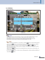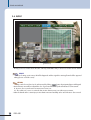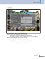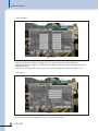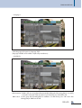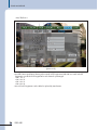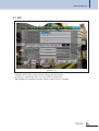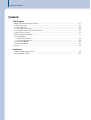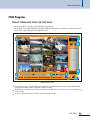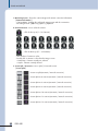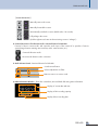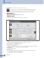
1
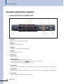
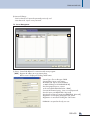
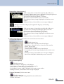
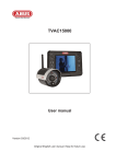
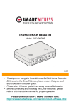
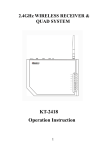
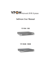
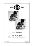
Operation Manual
Stand Alone DVR
DSR-430
STAND ALONE DVR
Welcome
A personal welcome to you from the management and employees of Inter-M
All of the co-workers here at Inter-M are dedicated to providing excellent products with inherently good value,
and we are delighted you have purchased one of our products.
We sincerely trust this product will provide years of satisfactory service, but if anything is not to your complete
satisfaction, we will endeavor to make things right.
Welcome to Inter-M, and thank you for becoming part of our worldwide extended family!
CAUTION
RISK OF ELECTRIC SHOCK
DO NOT OPEN
CAUTION: TO REDUCE THE RISK OF ELECTRIC SHOCK.
DO NOT REMOVE COVER (OR BACK).
This symbol is intended to alert the user to the
presence of uninsulated “dangerous voltage” within
the product’s enclosure that may be of sufficient
magnitude to constitute a risk of electric shock to
persons.
This symbol is intended to alert the user to the
presence of important operation and maintenance
(servicing) instructions in the literature accompanying
the appliance.
NO USER-SERVICEABLE PARTS INSIDE.
REFER SERVICING TO QUALIFIED SERVICE PERSONNEL.
WARNING
To prevent fire or shock hazard, do not
expose the unit to rain or moisture.
Caution: To prevent electric shock do not use this (polarized) plug with
an extension cord, receptacle or other outlet unless the blades
can be fully inserted to prevent blade exposure.
Attentions: Pour prévenir les chocs électriques ne pas utiliser cette
fiche polarisée avec un prolongateur, une prise de courant
on une autre sortie de courant, sauf si les lames peuvent
étre insérées à fond sans en laisser aucune partie à
découvert.
*Do not install this equipment in a confined space such as a book case or similar unit.
*The apparatus shall not be exposed to dripping or splashing and no objects filled with liquids, such vases, shall be placed on the apparatus.
*Worded: “WARNING FOR YOUR PROTECTION PLEASE READ THE FOLLOWING-WATER AND MOISTURE: Unit should not be used near
water(e.g. near a bathtub, washbowl, kitchen sink, laundry tub, in a wet basement, or near a swimming pool, etc). Care should be taken so than
objects do not fall and liquids are not spilled into the enclosure through openings.”
Service Instructions
*Worded: "Caution: These servicing instructions are for use by qualified service personnel only. To reduce the risk of electric shock, do not
perform any servicing other than that contained in the operating instructions unless you are qualified to do so."
*Location: Instruction Manual.
NOTE : This equipment has been tested and found to comply with the limits for a Class A digital device, pursuant to Part 15 of the FCC Rules. These
limits are designed to provide reasonable protection against harmful interference when the equipment is operated in a commercial
environment. This equipment generates, uses, and can radiate radio frequency energy and, if not installed and used in accordance with the
instruction manual, may cause harmful interference to radio communications. Operation of this equipment in a residential area is likely to cause
harmful interference in which case the user will be required to correct the interference at his own expense.
* It can be heated up if you use this product in closed box or ill-ventilated place.
2
DSR-430
STAND ALONE DVR
Contents
System Components.......................................................................................................................6
Introduction
1. System Features .............................................................................................................................6
2. Major Functions .............................................................................................................................7
Formation and Function of System
1. Led and Button of the Front Side ......................................................................................................8
2. The Back Side ..............................................................................................................................10
System Setup
1. Booting .......................................................................................................................................11
2. Live.............................................................................................................................................12
3. Set Up.........................................................................................................................................14
3-1. Recording ............................................................................................................................15
3-2. Play .....................................................................................................................................16
- Play and set a play ...............................................................................................................16
- Play .....................................................................................................................................17
3-3. Schedule ..............................................................................................................................19
3-4. Event....................................................................................................................................20
3-5. Network...............................................................................................................................21
3-6. Set up ..................................................................................................................................22
- Factory Default .....................................................................................................................22
- Date and Time ......................................................................................................................23
- Buzzer/Alarm ......................................................................................................................24
- Password .............................................................................................................................24
- Language .............................................................................................................................25
- Hard Disk.............................................................................................................................25
- Pan/Tilt/Zoom......................................................................................................................26
3-7. Live......................................................................................................................................27
Specifications ................................................................................................................................28
DSR-430
3
STAND ALONE DVR
Before you begin...
This operation manual is the guidebook against the program use method and a composition of DSR
system (below system).
Before using a system, certainly it tries to read the instruction manual certainly, it wishes.
After dissolving a packing to, it confirms the various component and the question sleeps system sale and question.
CAUTION
This is security product and please keep it from the electrical shock and impact.
Please avoid from high temperature and heavy humidity.
Recommend operation temperature -10'C ~ +40'C.
The breakdown due to the use of adaptor which is not included in the product can not be
guaranteed by the manufacture.
No Manufacturer guarantees HDD saved data.
No Manufacturer guarantees user's fault.
Please regularly backup important data from the system.
If HDD is necessary to be changed, you can only change it to ATA HDD.
Before using the recording function, you had better confirm the time set for the first thing not
to get the date incorrect.
Safety Notice
1. Before installing the product
- Take out the components and place them on a clean and dry area.
- Install in a well ventilated place.
- Do not install in areas of strong electrical or electromagnetic interference, such as in switchgear rooms
or near powerful loudspeakers etc.
- Avoid installing in areas with severe temperature changes such as garages and outbuildings.
- Do not install in direct sunlight or near sources of heat and avoid sources of vibration.
- Please check the mains voltage settings on the system before connecting the power cord.
- Having unpacked the system, we recommend retaining all packaging for future use in the event of
relocation or returning to manufacturer. To avoid the danger of suffocation, please dispose of the
plastic wrapping carefully.
4
DSR-430
STAND ALONE DVR
2. Notes on using the product
- Please make sure to read the user guide before using the system.
- Contact the supplier if the product does not function. Do not attempt to fix any internal problems as this
may void your warranty. The system contains static sensitive components.
- Do not operate the system or touch the power cord or outlet with wet hands.
- Do not use alcohol or solvent based products to clean the cabinet.
- Press the
button of keypad for 5secs before shutting down the system and confirm the power off
message. HDD is a possibly defected if you keep the Power on and off without the system OFF.
- Do not place any heavy items on top of the system.
- Do not move the system whilst powered up.
- In the event of any system failure where smoke or smells are present, turn off the system, remove the
mains plug and contact your supplier.
Manufacturers Guarantee
This system is guaranteed against failure within 1 year of the purchase date.
We reserve the right to replace components prior to the replacement of the complete system.
Do not attempt to repair any internal components as this may void warranty.
This guarantee does not cover instances of system abuse, physical damage or other issues beyond the
manufacturers control.
In the event of any failure, contact your supplier.
Free maintenance or replacement service is not applicable if:
1. The system was damaged due to user error or abuse.
2. The user did not follow the instructions in the user guide.
3. The rated voltage and frequency specified in the user guide were not observed.
4. Replacing of consumables or cleaning of the system is required.
5. System failure following repair by unauthorized personnel.
* The consuming width shift and equipment cleaning are excepted from maintenance conservativeness.
After the free maintenance period has expired, you can have your system upgraded or repaired by your
supplier. Should you require these services, please ask your supplier for more information.
Product Name
Product Number
Supplier / Telephone
Date of Purchase
Guarantee Period
Customer
Information
Name
Address
Telephone
- Please note other terms and conditions may vary with different suppliers.
- You should quote the information above when requesting maintenance or service.
DSR-430
5
STAND ALONE DVR
System Component
Please, dissolve a packing at the place which is flat and moisture less. And than, check the components as below.
Components of DSR System
DSR-430 MAIN UNIT
REMOTE CONTROLLER
BATTERY AAA 2pcs
USER MANUAL
ADAPTER
MOUSE
POWER CABLE
Introduction
What is the STAND-ALONE DVR?
As DVR of All in one type built in functions of DVR, Independent system was embodied.
Because stand-alone type have a high stability and convenience, it is going to replace DVR based PC.
System Features
1) Stability
Stand-Alone Type of Non OS base.
2) Convenient Characteristic
The menu set which is convenient due to an intuition use.
A variety of control interface : Mouse/Remote Controller/KeyPad
The support a search [Motion/Sensor/continuity/Motion+Sensor/Manual Recording Type]
3) Expendability
Remote control software gearing of Inter-M DVR Product(CMS).
Support ‘Explorer Viewer’
4) Technical Power
Non OS base User Interface embodiment.
5) Functions
Time-lapse/Event gearing/Post event recording.
Recording set up; classified by camera, days and time.
Built-in external sensor and perceptive function of motion.
6
DSR-430
STAND ALONE DVR
Main Functions of System
- Watching images of real time by four cameras.
- Provide a variety of user control interface.
- Easy to change languages and Video Type(NTSC/PAL).
The things you should be noticed.
- When power up, any key[keypad], except for base key (SET/ESC) in the front is not working under a
mouse connection.
- Without mouse connection, front key and remote control can control the system.
- The Product was released with a password ‘1234’.
- When set up the equipment the first time, confirm the set up time. If the time do not match with real time,
re-set up the time with reference to manual[3-6 Date and Time]
- For recording the first time, format HDD with reference to ‘hard disk’ part of manual [3-6 Hard Disk] prior
to use of the system or, recording will not be operated.
- NTSC Type Operation: Under pressing ESC key, Power up.
- PAL Type Operation: Under pressing
SET key, Power up.
- In case you lost the password for setting up, you should press the upward key at the same time of the
power connected. After checking the booting message, all the values set by user are default by pressing
the up key / right key / down key / left key in a row by auto-rebooting.
After all the rebooting, all the user setting values become to default.
DSR-430
7
STAND ALONE DVR
Formation and Function of System
1. LED AND BUTTON OF THE FRONT SIDE
1
2
3
4
5
6
7
9
8
SET
DSR-430
ACT
LINK
HDD
REC
POWER
USB
ESC
10
11
12
13
1. ACT LED
When used the network communication.
2. LINK LED
When connect with network.
3. HDD LED
When system is reading and writing HDD.
4. REC LED
When system is recording.
5. POWER LED
When power up.
6. MENU BUTTON
When select 4partition and menu in the screen.
To turn off the system, press key
for five seconds on the screen.
(confirm the OFF message and then shut the power).
7. CH1 BUTTON
When move to upwards of menu, select the camera1. and set up a password, [CH1] is used as the Key1.
8. CH2 BUTTON
When move to the right side of menu, select the camera2. and set up a password, [CH2] is used as the Key2.
9. SET BUTTON
Option of Setting up/keeping by hand operated.
8
DSR-430
STAND ALONE DVR
10. USB PORT
Image suspended of the Recording Play is kept via USB.(support Multi Card reader of USB Type.)
11. CH4 BUTTON
When move to the left side of menu, select the camera4. and set up a password, [CH4] is used as the Key4.
12. CH3 BUTTON
When move to downwards of menu, select the camera3. and set up a password, [CH3] is used as the Key3.
13. ESC BUTTON
Cancellation of seeing up/conclusion of/keeping by hand operated.
DSR-430
9
STAND ALONE DVR
2. THE BACK SIDE
1
2
3
4
5
6
7
1. POWER (DC JACK)
Use DC12V/3A adaptor with 160G HDD.
2. VIDEO INPUT (BNC)
Connect with cameras and external equipments.(NTSC/PAL)
3. VIDEO OUTPUT (BNC/S-VIDEO)
Connect with monitors for watching screen.(NTSC or PAL)
4. MOUSE (PS2)
Connect with a mouse for controlling the system.
(Power up after mouse connection makes only base keys of the front key are operated.)
5. LAN (RJ-45)
LAN is connected with RJ-45.(for client connection)
6. SENSOR INPUT
Provide input of four sensors.
7. ALARM OUTPUT
Connect with equipment of alarm output.(0.5A 125VAC, 1A 24VDC)
8. PTZ (RS-485)
P/T/Z cameras is controlled by RS-485 Communication.
10
DSR-430
8
STAND ALONE DVR
System Setup
NTSC or PAL Type is released; Language can be changed in set-up of menu.
- Under
SET key is pressed, power up ; the system is operated as PAL.
- Under
SET key is pressed, power up ; the system is operated as NTSC.
1. BOOTING
In the back side, connect with input/output and a mouse and than power up. It makes a booting as below [picture 1-1]
[picture 1-1]
‘Found Hard-Disk…’ message is disappeared, the system booting was concluded normally.
If you do not find a hard disk, ‘No Hard-Disk found’ message is shown. A damage of a hard disk, poor
connections of HDD or use of low level of electronic power adaptor are also shown like that.
The date, time, availability of hard disk is shown in the downward of screen.
To set up a product the first time, format HDD with reference to ‘Hard-Disk’ part of manual. [3-6 Hard Disk]
A mouse and keypad can not be used simultaneously.
(exclusive of
SET[Record] /
ESC[STOP])
When you power up without mouse connection, equipments can be controlled by remote control and key pad.
When you put the power ON only with the mouse connected, equipments can be controlled by only mouse.
(SESESET[Record Start] and ESC [Record Stop] of Keypad is operated.)
DSR-430
11
STAND ALONE DVR
2. LIVE
After booting normally, the live screen of four channels is shown as below.[picture 2-1]
[picture 2-1]
[picture 2-2]
12
DSR-430
STAND ALONE DVR
MOUSE
Full screen will be shown when you put the point each channel area and click on the left side of mouse.
Previous channel will be shown when you divide the screen into two and click on the left area with right
side of the mouse. (in case present screen is CH1, it will move to CH4)
Next channel movie will be shown when you click the right area with right side of mouse. And you will
go back to ‘Quad’ mode when click the left side of it.
KEYPAD
Full screen of each channel will be shown if you click CH1/CH/ /CH3/ CH4
/
of the keypad.
If there is no input Video signal, Blue screen Viewer will be generated such as CAMERA2, CAMERA3 of
the below 2-1 photos.
[picture 2-3]
When each channel is in recording status, the image will be shown as above.
Each of which means as below;
MA(Manual Recording) : You can save manual when click ‘SET’ button and stop to save when click
‘ESC’ button.
SC(Schedule Recording) : Schedule will be saved based on time and day set and will be shown in the monitor.
MO(Motion Recording) : If ‘motion’ happens to time and day set, it will be saved and shown in the monitor.
SE(Sensor Recording) : If detect of Sensor happens to time and day set, it will be saved shown in the monitor.
MO SE(Motion & Sensor Recording) : The sign ‘SE’ will be appeared and saved when it Motion or Sensor
detect, Motion & Sensor happen.
If you push the ‘S ET’ button, Manual Recording will get started.
If you push the ‘S ET’ button, Manual Recording will get finished.
DSR-430
13
STAND ALONE DVR
3. SET UP
You can see the windows MENU when first click “ °·” of Keypad or right button of a mouse.
Normally, password is not necessary to make a shipment.
The password;1234, however, is necessary to enter and change the menu.
* Password can be input with keypad and each channel button stands for the number.
(
=1,
=2,
=3,
=4)
[picture 3-1]
MOUSE
- A left button
• Choose the menu
• Change the value on it possible to use mouse scroll.
• Choose the menu Field(REC/PLAY/SCH/EVENT/NET/SETUP/LIVE)
- A right button
• Close the menu
KEYPAD
-S
- ES
14
/ UP/D/WN/LEF//RIGHT : Move a cursor
: • Choose a menu
: • Change the value
ET : Save the value revised and be out of the menu.
C : Not save the figure revised and be out of the menu.
DSR-430
STAND ALONE DVR
3-1. RECORDING
Save ‘recording set’ as channels.
[picture 3-2]
- Channel : Choose the channel [choice options: 1~4]
- Resolution : Choose a recording resolution of a channel chosen
- Resolution : (Choice options: NTSC 704X240, 352X240 / PAL 704X288, 352X288)
- Quality : Choose a recording quality of a channel chosen.
- Quality : (Choice options : minimum/low/middle/high/maximum)
- FPS : Set a recording framerate of a channel chosen per a second.
- FPS : Maximum recording frame at 704x240 is 15FPS per a second for NTSC and 704x288 is 12.5FPS per
- FPS : a second for PAL.
- Recording Time After a Motion Detection : Set a recording time after a motion occurs.
- Recording Time After a Sensor Occurrence : Set a recording time after a sensor occurs.
- Sensor Connection : Choose a sensor linked a channel chosen.
- Sensor connection: (according to the sensor chosen occurs sensor recording and alarm output)
* Sensor Recording isn’t made if you do not choose a connection of Sensor of the ‘REC’ Field in spite of a sensor
recording is set to the ’SCH’ Field and it starts to work .
- Confirmation/Cancellation : After set a channel, press ‘OK’ or ‘ESC’.
DSR-430
15
STAND ALONE DVR
3-2. PLAY
< Play and set a play >
[picture 3-3]
- Channel : Choose the channel you would like to search.
- Date : Choose the date you would like to search.
- LOAD : Choose the way recorded and search for a recording file.
- Read : After choosing among Emergency/Continuous/Motion+Sensor/Motion/Sensor, push the ‘LOAD’ button
- Read : and you can only find out the file regarding the way of recording.
- Confirmation : After choosing the hour , press the ‘OK’ button and let it play.
- Confirmation : (The playing unit of recording file is 15minutes.)
16
DSR-430
STAND ALONE DVR
< Play >
As above, you can find the date and time of the movie playing the upper side of the screen.
[picture 3-4]
[picture 3-5]
DSR-430
17
STAND ALONE DVR
MOUSE
- The movie is played with full screen if you scroll and click the Mouse once more to get the size back. You can
control the speed of a play with scrolling the Mouse.
- The screen is stopped by clicking the scroll and moved pre or post one frame by rolling the scroll up and down.
When it is stopped, you can click the left button for a reverse play and the right button for a play.
- To back to the ‘SCH’ menu, click the right button of the mouse.
KEYPAD
- In case using keypad, full screen will be played by clicking
- You can control the speed of a play by using U
- In order to stop playing, you need to press
you click the s
’ button and back to small(PIP) by pressing it again.
P/DOWN button.
LE FT or RIGHT button. Also you can move forward as a frame. If
LE FT or RIGHT button in stop mode, it starts to play reverse and forward.
* The operation of keypad and remote control is same. The remote control can be used by setting numbers.
18
DSR-430
STAND ALONE DVR
3-3. SCHEDULE
How to set a time table.
[picture 3-6]
MOUSE
- Click a left button of the mouse(in the left upper outside area of time table cell), all date will be set or clear.
- Click a left button of the mouse in the area of 0~23, all the date for the time will be set or clear.
- Click a left button of the mouse in the area of the date, all the time for the date will be set or clear
- Put the pointer in each sell and click a left button, the sell pointed will be set or clear.
KEYPAD
- The time for the date pointed will be set or clear when you click the ‘ °·’ button of a first sell of left upper side.
- When press the l e ft button in each cell, all dates for the time is chosen (removal of the choice : the lower
directed key) and you can move the rows chosen to right and left with l e ft and l e ft button.
- When choose interactive key, it will be reversed to the standard columns of the cells selected. (Removal of the
choice: the right directed key)
- When you press ‘ °·’ button from the column standard, the entire column chosen is set/clear and you can
move the menu un and down.
- If you press the l e ft button in a column chosen, it will be appeared as a cell area and the entire will be set/
clear with the ‘ °·’ button.
DSR-430
19
STAND ALONE DVR
3-4. EVENT
[picture 3-7]
- The way you choose a motion area is the same as the way of date table. And you can choose a motion area as channel.
MOUSE
- In the event of setting a motion area, PIP will be happened and the original Live Moving Channel will be appeared
nothing.(shown as a black screen).
KEYPAD
- Sensibility can be chosen from 0 to 63 and increased by clicking
‘°·’ button when inputting figures with keypad.
- Motion detection area will be indicated the color of green and the color of pink will indicate a real movement.
0 : A sensor does not work even if movement sensor area is set.
63 : The condition of a sensor is continued when motion detection area is set without any movement.
- Under the channel with no camera input, motion detection area and sensibility can be set but the sensor does not work.
20
DSR-430
STAND ALONE DVR
3-5. NETWORK
[picture 3-8]
- DHCP : When the value is ‘ON’, IP is automatically delivered and set .
- IP Address : Put the IP address delivered from Internet Service Provider.
- IP address : Rebooting will be needed for a renewal when you try to set DHCP function.
- IP address : Please make a use after being confirmed by Network operator as for a possibility of DHCP use.
- Subnet Mask : Input the subnet mask delivered by Network manager.
- Subnet mask : 255.255.255.0 is used in basic in standard network.
- Gateway : Input the gateway delivered by Network manager.
- Gateway : Gateway indicates generally IP of the switch which routing from LAN to WAN.
- Service Port : The service port used in network communication.
- Service port : It is ok to input the port No. opened by network manager in firewall.
- Service port : However it is unnecessary to set a service port at the basic use of internet.
DSR-430
21
STAND ALONE DVR
3-6. SETUP
< Factory Default >
[picture 3-9]
- For factory default, select ‘Factory Default’ in “SELECT MENU” field and ‘ON’ in “Factory Set” field. And then
press “Save” button.
- If you click on “OK” before pressing “Save” button, the setting will be restored to the factory default as well.
- The set up screen disappear when click on “OK”.
22
DSR-430
STAND ALONE DVR
< Date and Time >
[picture 3-10]
Set up the date and time.
MOUSE
- You can select and adjust date and time by clicking on the left button.
- With scroll bar, numbers can be increased or decreased.
KEYPAD
- The operation with remote controller is the same as with keypad.
- Use
[°Á],
[°Ê] keys to move between fields and use
[°Á],
[°Ê] keys to increase or decrease
numbers.
- For “SAVE” and “OK”, press
button on keypad [remote controller :
].
DSR-430
23
STAND ALONE DVR
< Buzzer/Alarm >
[picture 3-11]
- Set the period of buzzer or alarm according to the sensor setting of channels in “REC” Field menu.
- Set the period of buzzer or alarm for each channel according to the detection area and sensitivity of motion in
“EVENT” Field menu.
- In case buzzer or alarm go off continuously, you can stop it by setting the time of buzzer or alarm to “0”.
< Password >
[picture 3-12]
- Password is necessary for changing the set up in case password is specified.
24
DSR-430
STAND ALONE DVR
< Language >
[picture 3-13]
- Set the language of the system in “Language” field.
(Languages available can be added or replaced by manufacturer.)
< Hard Disk >
[picture 3-14]
- HDD Overwrite : If HDD is full, save current data after automatically deleting the oldest saving data. In case [OFF]
is selected in “Overwrite” field, new data is not recorded any more when HDD is full.
- HDD Format : Use the system after formatting HDD for installation. For HDD format, press “OK” button after
selecting [ON] in “HDD Format” field.
DSR-430
25
STAND ALONE DVR
< Pan/Tilt/Zoom >
[picture 3-15]
- Input PTZ Camera specification referring to the manuals of PTZ equipments. DSR-430 can control each PTZ
equipment in case the ID of PTZ equipment for each channel is prearranged.
• CH 1 : ID “1”
• CH 2 : ID “2”
• CH 3 : ID “3”
• CH 4 : ID “4”
- Protocols for PTZ equipments can be added or replaced by manufacturer.
26
DSR-430
STAND ALONE DVR
3-7. LIVE
[picture 3-16]
- Display the camera names on the screen with setting up the camera names.
- Input device is activated when click on the camera name of each channel.
- Adjust Brightness/Contrast/Hue/Saturation with the scroll bar of mouse or keypad.
DSR-430
27
STAND ALONE DVR
Specifications
DSR-430
Camera Input
Video Output
Sensor
Relay
Mouse/USB
Display/Recording NTSC
Speed (FPS)
PAL
NTSC
Live Resolution
PAL
Recording
NTSC
Resolution
PAL
Screen Division
Compression
Recording Type
Search
Speed
Network
Application
Web Browser
Motion Detection
Internal Buzzer
Pan/Tilt Camera
HDD
Operating Temperature
Power Source
Power Consumption
Weight
Dimensions
4 CH
SVHS : 1 Y/C, CVBS : 1 BNC(Monitor)
4 CH
1 CH(1~60sec, Continuance)
PS2 1 Port/USB A 1 Port
Up to 120fps
Up to 100fps
720 x 480
720 x 576
704 x 240(30fps), 352 x 240(120fps)
704 x 288(25fps), 352 x 288(100fps)
1, 4
M-JPEG
Manual, Motion, Sensor, Motion+Sensor, Schedule
Date, Time(Quarter), Event(Motion, Alarm)
SS, S, 1, F, FF Forward/Backward
10/100mb Ethernet(RJ45 Only), (TCP/IP, DHCP)
UCM, DDNS
ActiveX
Multi-Zones, Multi-Channels
Sensor Input, Motion Detection
RS-485 Interface
IDE HDD 1EA
-10°C ~ +40°C
DC 12V, 3A
11W
2.7kg/5lb
320(W) x 44(H) x 250(D)mm/12.6(W) x 1.7(H) x 10(D)in
Specifications and design subject to change without notice.
28
DSR-430
STAND ALONE DVR
Contents
CMS Program
Default Screen and Using the Functions. ...........................................................................................31
1. Monitoring Screen......................................................................................................................32
2. Camera Selection .......................................................................................................................32
3. Screen Split / Conversion ...........................................................................................................32
4. Connect/Disconnect of bi-direction Audio ....................................................................................33
5. Audio Volume Control ................................................................................................................33
6. Index Information Window..........................................................................................................33
7. Function Buttons
7-1. Environment Setup...............................................................................................................34
7-2. Server Management ............................................................................................................35
8. Function Tab Buttons...................................................................................................................36
9. Connect/Disconnect ...................................................................................................................37
10. Quit ........................................................................................................................................38
Supplement
1. Understanding of Dynamic IP ......................................................................................................39
2. Recording Time Table .................................................................................................................40
STAND ALONE DVR
CMS Program
DEFAULT SCREEN AND USING THE FUNCTIONS
- CMS program allows connecting to Inter-M DVR through networks.
- CMS program is for integrated management of Inter-M DVR and some functions are restrictive according to the model.
- Some functions can be changed for new DVR in the future.
6
1
7
8
3
4
2
5
9
10
< CMS Default Screen >
Function button may not be naturally executed at low line speed depending on the line speed of [CMS Default
Screen] network. Wait a minute until function will be executed.
Problem may occur that the screen stops or remains in a standby status for a long time when consecutively using
function button.
Connect or disconnect button is used for connection through networks.
DSR-430
31
STAND ALONE DVR
1. Monitoring Screen : Shows the camera image and camera connection information.
[ Camera Information ]
- Camera Name : Displays the configured camera name and the current time
- Recording & Event : [R]Record, [S]Sensor, [M]Motion
2. Camera Selection : Use to select the camera
: Click for Group A (1 ~ 16 Cameras)
: Click for B Group (17 ~ 32 Cameras)
- Click number of camera to select.
- Double-click’ a camera to select from the image screen.
• Dark Gray : Camera currently not selected
• Purple : Camera currently selected
3. Screen Split / Conversion : Use to Split / Convert the screen.
[ Screen Split ]
32
-
: Screen not split (automatic / manual conversion)
-
: Screen split into 4 sections (automatic / manual conversion)
-
: Screen split into 6 sections (automatic / manual conversion)
-
: Screen split into 9 sections (automatic / manual conversion)
-
: Screen split into 10 sections (automatic / manual conversion)
-
: Screen split into 13 sections (automatic / manual conversion)
-
: Screen split into 16 sections (automatic / manual conversion)
DSR-430
STAND ALONE DVR
[ Screen Conversion ]
-
: Manually reverses the screen.
-
: Manually Forwards the screen.
-
: Automatically switches the screen. (default value: 10 seconds)
-
: Fully enlarges the screen.
-
: (click the right mouse button in the monitoring screen to “enlarge” )
4. Connect/Disconnect of bi-direction Audio: restricted function for DSR-430
Function to listen to remote audio and output the audio input of the current PC to speakers of remote
system.(Usage: Remote warning announcement, audio communication, etc.)
: Connect bi-direction audio.
: Disconnect bi-direction audio connection
5. Audio Volume Control : Restricted function for DSR-430
: Sound removal button
: Volume adjustment scroll bar
: Button to remove or restore sound
6. Index Information Window : Shows the current date, time and hard disk saving status information.
Display of current date and time
Display of HD recording capacity
Display oldest recording date
DSR-430
33
STAND ALONE DVR
7. Function Button : This is function to set or retrieve environment.
-
Environment Setup : Sets environment related with CMS (Client Manager System).
[ Authorization Procedure ] Performs authorization procedure for environment setting.
(Default Password : “1111”)
If authorization is successfully done, following window is displayed.
7-1. Environment Setup
1
2
3
4
5
1) System
- Automatic Screen Conversion Price (unit: second) : Sets interval of automatic screen conversion time (second).
- Display of Character on Image: Checks whether use will be done or sets font.
- Basic Screen Mode : Selects initial division screen
2) Dynamic IP Server : Sets dynamic IP server.
- Type : Choose the type of DVR
- Dynamic IP Server Address : Displays server address to support Dynamic IP. (128.134.140.160)
- Server Response Time : Sets response time in request of Dynamic IP.
3) Recording Setup
- Sets a drive to record data.
4) Reconnection Setup
- Reconnect : Reconnect where connection with the server is broken due to network problems.
- Use : Sets whether re-Connect for use will be done
- Reconnect InTerval : Sets re-Connect trial interval.
34
DSR-430
STAND ALONE DVR
5) Password Change
- Previous Password : Inputs the password previously used
- New Password : Inputs a new password.
7-2. Server Management
2
1
1) Server : Controls ID address for connection with server program.
[ Add ] : Registers IP address at a new remote place.
Below screen is displayed if clicking "Add" button.
- Server Type : Choose the type of DVR
- Server Name : Inputs server name.
- IP Address/ID : Inputs server IP address
or MAC Address[ex: XX-XX-XX-XX-XX-XX]
- Port: Designated a port to connect
to the server.[DSR-430 Default Port : 5000]
- Connect Information Saving : Saves user and password.
- User ID: Inputs user ID[DSR-430 : Not need]
- User Password: Inputs user password[DSR-430 : Not need]
- Registration is executed if clicking the “OK” button
- Registration is cancelled if clicking the “OK” button
* DSR-430 is accepted to the only one user.
DSR-430
35
STAND ALONE DVR
[ Modify ] : Modifies IP address of the registered remote location.
- Selects a list to modify from the server register list.
- Click “Modify” button.
- A server information window is displayed as in Add.
- Modifies the part to modify.
- Modify work is executed if clicking “OK” button.
- Modify work is cancelled if clicking “Cancel” button.
[ Remove ] : Deletes IP address of the already registered remote location.
- Selects a list to delete from the server register list.
- Click “Remove” button.
- Select the “OK” button from a window to check whether “Remove” will be done.
2) Group : Controls IP addresses of the remote location as group.
[ Add ] : Registers a new group. Below screen is displayed if clicking “Add” button.
- Group Name : Inputs a group name.
- Explanation : Inputs simple explanation for the group name.
[ Modify ] : Modifies the already registered group.
- Selects a list to modify from the group list.
- Click “Modify” button.
- A group information window is displayed as in the left figure.
- Select server and camera.
- Modify work is executed if clicking “OK” button.
- Modify work is cancelled if clicking “Cancel” button.
[ Remove ] : Delete the already registered group.
- Select a list to delete from the group register list.
- Click “Remove” button.
- Select the “OK” button from a window to check whether “Remove” will be done.
Search Function: Executes Search.
8. Function Tab Button : Functions of logo, camera status, log, pan tilt control, server control and group control.
8. Function Tab Button : (DSR-430 is not accepted to use the network PTZ Control)
[ Camera 1 Group ] : Displays camera status from No.1 camera through No.16.
[ Camera 2 Group ] : Displays camera status from No.17 camera through No.32]
[ Server ] : Controls list of the remote location registered in server control setting.
36
DSR-430
STAND ALONE DVR
[ Remote Place Connect Sequence ]
- Clicks a server name to Connect from server lists with a left mouse.
- “Connect “/ “Remote Setup” menu is displayed if clicking the right mouse
button.[DSR-430: Remote Setup not support.]
- Try Connect to the server in selection of “Connect”.
(All cameras connected with the server are Connected.)
- If succeeding in Connect, image is displayed on the monitor screen
window.
- If failing in Connect, Connect failure error message is displayed.
[ Group ] : Controls list of the group list registered in the group control setting.
[ Group Connect Sequence ]
- Clicks a group name to Connect from server lists with a left mouse.
- "Connect" menu is displayed if clicking the right mouse button.
- Try Connect to the servers in selection of "Connect".
(Connect to all servers included in the group is tried.)
- If succeeding in Connect, image is displayed on the monitor screen
window.
- If failing in Connect, Connect failure error message is displayed.
9. Connect / Disconnect: : Connect to the server or DisConnect Connect from it.
[ Server Connect Sequence ]
Click the Connect icon.
- The Connect window is displayed as in the left figure.
- Server Name : Selects the server to Connect from the server list.
- User ID : Inputs user ID.
- Password : Inputs password.
- "Server Connect" : Clicks the server Connect button.
- If succeeding in Connect, image is displayed on the monitor screen
window.
- If failing in Connect, Connect failure error message is displayed.
[Not need to the ID/PW for DSR-430 by remote connection.]
[Group Connect Sequence]
Click the Connect icon.
- The Connect window is displayed as in the left figure.
- Group Name : Selects a group to Connect from the group list.
- "Group Connect" : Clicks the group Connect button.
- If succeeding in Connect, image is displayed on the monitor screen window.
- If failing in Connect, Connect failure error message is displayed.
[ Connect / Disconnect ] : In Disconnect status.
Click the Connect icon;
- A check window is displayed asking whether Disconnect will be done.
- Click the "OK" button.
DSR-430
37
STAND ALONE DVR
10. Quit : Quit program.
Clicks the end icon.
- The authorization window is displayed.
- Click "OK" button after inputting password.
38
DSR-430
STAND ALONE DVR
Supplement
1. UNDERSTANDING OF DYNAMIC IP
This is method that new Internet IP is assigned whenever starting the system connected with DHCP
(Dynamic Host Configuration Protocol) server, which is not an independent IP fixed to Internet.
To use such system as an independent server, a middle media server to relay IP changed from time to time
is required, and the system that plays such a role is a DIMS(Dynamic IP Management Server) system.
[ Connection for Fixed IP ]
Web Server
INTERNET
DSR-430
Client
[ Connection for Dynamic IP ]
INTERNET
DSR-430
Client
Dynamic IP
Web Server
Dynamic IP Server
(To support "Dynamic IP Function", you must register the user in the "Dynamic IP Server"
(http://www.inter-mdvr.co.kr))
CMS is integrated software as to a group of DVR of Inter-M and could possibly have some functions
unsupplied as a integrated management system of a diversity of products.
DSR-430
39
STAND ALONE DVR
2. RECORDING TIME TABLE
2. RECORDING TIME TABLE
Recording
Resolution
352
X
240
704
X
240
Recording
Resolution
352
X
240
704
X
240
Recording
Resolution
352
X
240
HDD:160G
Value: Days
Quality
KB/1pic
Mbuye/Hour
7.5fps
1ch REC
7.5fps REC by Channel
2ch REC
3ch REC
LOWEST
8
216
30.9
15.4
10.3
7.7
LOW
9
243
27.4
13.7
9.1
6.9
NORMAL
10
270
24.7
12.3
8.2
6.2
HIGH
12
324
20.6
10.3
6.9
5.1
HIGHEST
19
513
13.0
6.5
4.3
3.2
LOWEST
13
351
19.0
9.5
6.3
4.7
LOW
14
378
17.6
8.8
5.9
4.4
NORMAL
16
432
15.4
7.7
5.1
3.9
HIGH
20
540
12.3
6.2
4.1
3.1
HIGHEST
26
702
9.5
4.7
3.2
2.4
Quality
KB/1pic
Mbuye/Hour
15fps
1ch REC
LOWEST
8
432
15.4
7.7
5.1
3.9
LOW
9
486
13.7
6.9
4.6
3.4
NORMAL
10
540
12.3
6.2
4.1
3.1
HIGH
12
648
10.3
5.1
3.4
2.6
HIGHEST
19
1026
6.5
3.2
2.2
1.6
LOWEST
13
702
9.5
4.7
3.2
2.4
LOW
14
756
8.8
4.4
2.9
2.2
NORMAL
16
864
7.7
3.9
2.6
1.9
HIGH
20
1080
6.2
3.1
2.1
1.5
HIGHEST
26
1404
4.7
2.4
1.6
1.2
Quality
KB/1pic
Mbuye/Hour
30fps
1ch REC
LOWEST
8
864
7.7
3.9
2.6
1.9
LOW
9
972
6.9
3.4
2.3
1.7
NORMAL
10
1080
6.2
3.1
2.1
1.5
HIGH
12
1296
5.1
2.6
1.7
1.3
HIGHEST
19
2054
3.2
1.6
1.1
0.8
15fps REC by Channel
2ch REC
3ch REC
30fps REC by Channel
2ch REC
3ch REC
4ch REC
4ch REC
4ch REC
* 704 X 240 Maximum Recording Frame = 15 Frame/sec
40
DSR-430
MADE IN KOREA
www.inter-m.com
2007. 7 9007302120