1
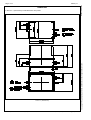
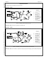
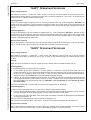
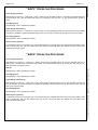
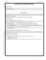
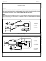
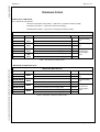
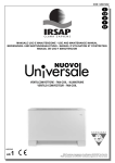
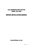
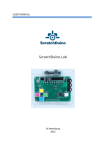
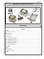
Pag.1 of 16 Edition 18/02/2003 PZB S.p.A. PNEUMATIC SHIFTING UNIT "AIR PLUS" USER MANUAL CONTENTS Copyright – Reproduction prohibited. Listed data can be changed without notice. GENERAL............................................................................................................................................................................ 2 PNEUMATIC SYSTEM “AIR-PLUS” ........................................................................................................................................ 2 SPECIFICATIONS ............................................................................................................................................................... 3 WORKING CONDITIONS ........................................................................................................................................................ 3 DIMENSIONS ....................................................................................................................................................................... 4 AVAILABLE VERSIONS ........................................................................................................................................................... 5 “KAP1” OPERATING PROCEDURE .................................................................................................................................. 7 “KAP2” OPERATING PROCEDURE .................................................................................................................................. 7 “KAP3” OPERATING PROCEDURE .................................................................................................................................. 8 “KAP4” OPERATING PROCEDURE .................................................................................................................................. 8 FUNCTIONAL SYSTEM CONTROL.................................................................................................................................... 9 INSTALLATION ................................................................................................................................................................. 10 SERVICE............................................................................................................................................................................ 12 ORDERING CODES .......................................................................................................................................................... 13 KIT “AIR-PLUS” ACCESSORY ............................................................................................................................................ 15 WARNING.......................................................................................................................................................................... 16 PZB S.p.A. – 40012 Calderara di Reno (BO) Italy – Via Persicetana, 2 – Tel. 0516460511 – Fax 051728528 – http://www.pzbitaly.com - E-mail: [email protected] PZB S.p.A. GENERAL Edition 18/02/2003 Pag.2 of 16 Even nowdays it is possible to find some vehicles which are not equipped with air compressor, since the braking system is mechanically operated. Such vehicles can be equipped with power take offs as well as the other vehicles equipped with the air compressor, along with one or more hydraulic circuits for a tipper with relevant auxiliary functions (krane behind the cabin etc.). In case the vehicle is equipped with an air compressor, the hydraulic circuit can be operated by a low-cost pneuamtic control. In this case PTOs and tipping valve with pneumatic shifting can be used. On the contrary, if the vehicle has no air compressor, the PTO and the whole hydraulic circuit can be mechanically operated. It is well known that the pneumatic control is by far the most reliable one and the easiest to install and to operate, beside the fact that it is also the less expensive. PNEUMATIC SYSTEM “AIR-PLUS” This “PNEUMATIC SYSTEM” is capable to generate the required compressed air necessary to the shift a pneumatically controlled P.T.O. In this way it is possible to fit onto almos any vehicle PTOs with pneumatic shifting, which are, as already said the mst reliable and less expensive ones. This system is called “AIR-PLUS” and it’s made of a compressor with reduced dimensions, operated by means of suitable switch, and it is capable of suppling sufficient compressed air in order to correctly engage the PTO. The whole system can be controlled by an electronic device controlling the complete pneumatic functions. - Shifting of a PTO with no electronic control (Model KAP1) - Shifting of a PTO with electronic control (Model KAP2) - Shifting of a PTO without electronic control and of an alectrically operated tipping valve (Model KAP3) - Shifting of a PTO with electronic control and of an alectrically operated tipping valve (Model KAP4) Every above version is available both with 12 VDC and 24 VDC voltage. The electronic control system developed for versions “KAP2” and “KAP4”, allows different configurations which can easily be adapted to custom’s needs, once the AIR-PLUS is installed. The AIR-PLUS range of compressor is completed with various electric control kits to be chosen according to vehicle specifications and features. SYSTEM RELIABILITY AND HOMOLOGATION “AIR-PLUS” had to undergo several tests on our lab benches, which allowed us to develop e very reliable product capable to satisfy even the heavieast working conditions. Other tests have been done directly on the vehicles operating for a certain amount of time “on the field” under sever working conditions. Further test sessions have ben run at TÜV laboratories, achieving proper certification also concerning electromagnetic compatibility of the built in electronic circuit board. (Test Report RD 2000 / 201 Council Directive 95/54/EC Annex VII-VIII). PZB S.p.A. – 40012 Calderara di Reno (BO) Italy – Via Persicetana, 2 – Tel. 0516460511 – Fax 051728528 – http://www.pzbitaly.com - E-mail: [email protected] Copyright – Reproduction prohibited. Listed data can be changed without notice. 4 different versions for the following applications have been released: Pag.3 of 16 Edition 18/02/2003 PZB S.p.A. SPECIFICATIONS In Table 1 (Specifications) “AIR-PLUS” equipment specifications are listed SPECIFICATION VALUE 3 Air flow at 5 bar dm /min. 1,2 2 3 Displacement cm /rev. 3,9 Maximum pressure bar 6 Average working pressure bar 4,5 Minimum working pressure bar 4 Engine speed at 5 bar rpm 1500 2500 Sound level ** B(A) 9.5 9.6 Noise level ** dB(A) 88 89 Voltage V 12V 24V Absorbed current A 6A 3,5A Table 1 (Specifications) Average full regime achieving time at 5 bar sec 2 Weight kg 1,75 Note ** Values measured in semi-anechoic roomwith the operator equipped with a phonometer at his hear standing one meter away WORKING CONDITIONS AIR-PLUS can work at the envirnmental conditions listed in Table 2 – (Environmental conditions). MAX. VALUE MIN. VALUE °C +60° -15° - 60% - Max. Single working cycle “S1” sec. 5 - Max. multiple working cycle “S2” sec. 15 - Idle time “S3” after “S2” min. - 10 °C 500 - Copyright – Reproduction prohibited. Listed data can be changed without notice. SPECIFICATION InstallationTemperature Relative Humidity Glow wire lest test Table 2 – (Environmental conditions) Important Notice Whenever relative humidity should overcome value listed in Table 2 – (Environmental conditions), peridodically check the quantity of moisture inthe inlet air pipes and possibly carry on proper circuit drainage Picture 1 – (Compressor performance) PZB S.p.A. – 40012 Calderara di Reno (BO) Italy – Via Persicetana, 2 – Tel. 0516460511 – Fax 051728528 – http://www.pzbitaly.com - E-mail: [email protected] DIMENSIONS In Picture 2 – (Dimensions) overall dimensions are rported Picture 2 – (Dimensions) PZB S.p.A. – 40012 Calderara di Reno (BO) Italy – Via Persicetana, 2 – Tel. 0516460511 – Fax 051728528 – http://www.pzbitaly.com - E-mail: [email protected] Edition 18/02/2003 PZB S.p.A. Copyright – Reproduction prohibited. Listed data can be changed without notice. Pag.4 of 16 Pag.5 of 16 Edition 18/02/2003 PZB S.p.A. AVAILABLE VERSIONS Five different versions are availble for the “AIR-PLUS” kit: AIR-PLUS – “KAP1” Breakdown ♦ ♦ ♦ ♦ ♦ ♦ ♦ ♦ 1) - KIT AIR-PLUS 2) - PTO 3) - on-off switch 5) – AIR-PLUS Kit lamp on 4) – Engaged PTO lamp (Optional) 6) – AIR-PLUS power supply lamp (optional) 7) – AIR-PLUS Kit power supply key (optional) 8) – Fuse obligatory Picture 3 – (“AIR-PLUS – KAP1” version for PTO only) “AIR-PLUS – KAP1” this version is required for PTO shifting only. Copyright – Reproduction prohibited. Listed data can be changed without notice. AIR-PLUS – “KAP2” Breakdown ♦ ♦ ♦ ♦ ♦ ♦ ♦ ♦ ♦ 1) - AIR-PLUS KIT 2) – PTO 3) – Onn-Off switch 4) Engaged PTO lamp (Optional) 5) - AIR-PLUS Kit lamp on 6) – End-stroke for clutch pedal 7) – Power supply lamp (optional) 8) - AIR-PLUS Kit power supply key (optional) 9) – Fuse obligatory Picture 4 – (“AIR-PLUS” – “KAP2” version with electronic control for PTO only) “AIR-PLUS – KAP2” version suitable for applications requiring PTO pneumatic shifting only with auxiliary shifting devices. PZB S.p.A. – 40012 Calderara di Reno (BO) Italy – Via Persicetana, 2 – Tel. 0516460511 – Fax 051728528 – http://www.pzbitaly.com - E-mail: [email protected] PZB S.p.A. AIR-PLUS – KAP3 Breakdown ♦ ♦ ♦ ♦ ♦ ♦ ♦ ♦ ♦ ♦ ♦ ♦ ♦ ♦ 1) - KIT AIR-PLUS 2) - PTO 3) – Onn-Off switch 4) – PTO ON lamp (optional) 5) – AIR-PLUS on lamp 6) – Buzzer (optional) 7) – Tipping Lamp (optiona)l 8) – 1-0-2 switch to control tipper rising and lowering 9) – Tipping valve 10) – Power supply lamp (optional) 11) – Power supply key (optional) 12) - Fuse obligatory 13) – End stroke control switch (optional) 14) Pressure switch tipper Edition 18/02/2003 Pag.6 of 16 Picture 5 – (“AIR-PLUS – KAP3” version for PTO and tipping valve) “AIR-PLUS – KAP3” version suitable for PTOs with pneumatic shifting and electrically operated tipping valve. AIR-PLUS – KAP4 ♦ ♦ ♦ ♦ ♦ ♦ ♦ ♦ ♦ ♦ ♦ ♦ ♦ ♦ ♦ 1) - KIT AIR-PLUS 2) - PTO 3) – Onn-Off switch 4) – PTO ON lamp (optional) 5) – AIR-PLUS on lamp 6) – Buzzer (optional) 7) – Tipping Lamp (optional) 8) – 1-0-2 switch to control tipper rising and lowering 9) – Tipping valve 10) – Clutch end-stroke 11) – Power supply lamp (optional) 12) – Power supply key (optional) 13) – Fuse obligatory 14) – End stroke control switch (optional) 14) Pressure switch tipper Picture 6 – (“AIR-PLUS – KAP4” electronically controlled version for PTO and TIPPING VALVE) “AIR-PLUS – KAP4” version suitable for PTOs with pneumatic shifting and electrically operated tipping valve. PZB S.p.A. – 40012 Calderara di Reno (BO) Italy – Via Persicetana, 2 – Tel. 0516460511 – Fax 051728528 – http://www.pzbitaly.com - E-mail: [email protected] Copyright – Reproduction prohibited. Listed data can be changed without notice. Breakdown Pag.7 of 16 Edition 18/02/2003 PZB S.p.A. “KAP1” OPERATING PROCEDURE Power Supply (optional) Wit reference to Picture 3 – (“AIR-PLUS – KAP1” version for PTO only), the whole system can be switched only if the relevant electric kit with safety key (optional) has been fitted. In this case rotationg key “7” into Pos. “I” will permanently switch lamp “6” on, indicating the the system is active. PTO Engagement In order to properly engage engage the PTO it is necessary to operate switch “3”. In this configuration “KIT-KAP1” will control the proper engagement of the PTO without checking the position of the clutch pedal. At the same time lamp “5” will light up. In case the PTO is equipped with with an engagement control switch, when the PTO is engaged lamp “4” will light up. PTO Disengagement In order to disengage the PTO it is necessary to release switch “3” . In this configuration “KIT-KAP1”, will make air flow out obtaining PTO disengagement. Also in this case the disengagement ill take place without taking care of clutch pedal position. Once switch “3” gets released, lamp “5” will turn off. In case the PTO is equipped with a control switch, once the PTO is disengaged lamp “4” will turn off. Disconnection (optional) System disconnection can be necessary only if the relevant safety key electric kit has been fitted. In this case by rotating key “7” into “0” position will turn off lamp “6” indicating that the system is not active any longer. “KAP2” OPERATING PROCEDURE Power Supply (optional) With reference to Picture 4 – (“AIR-PLUS” – “KAP2” version with electronic control for PTO only), if the key operated electric kit has been fitted, by rotating key “8” into pos. “I” lamp “7” will permanently light up to indicate that the system is active. Copyright – Reproduction prohibited. Listed data can be changed without notice. Start up When the system is switched on, lamp “5” wil light up for two seconds and the it will authomatically turn off. PTO Engagement To properly engage the PTO please follow the next steps : in case sensor “6” has been installed on the clutch pedal, it is necessary to fully push clutch pedal and in this position push switch “3”. Once proper engagement pressure has been achieved, lamp “5” will permanently light up. At this point it is possible to relase clutch pedal. In case the clutch pedal gets incidentally released during the engagment of the PTO, the KAP2 device will authomatically disengage the PTO. If sensor “6” has not been installed on the clutch pedal, once switch “3” has been pressed, the compressor will shift PTO engagement device into place without caring of any other controlling device. Once engagement pressure has been achievedlamp “5” will permanently light up. (CAUTION: in this configuration it is not possible to control the clutch pedal!). If the PTO is equipped with a control switch , once the PTO is engaged lamp “4” will light up. PTO Disengagement In order to properly disengage the PTO it is necessary to follow the steps listed here below: If sensor “6” has been fitted, pushing clutch pedal a second time will authomatically disconnect the system. The PTO won’t get disengaged by simply pressing button “3”, but it will be necessary to press clutch. In case sensor “6” hasn’t been fitted on the clutch pedal and properly connected, the disengagement will take place by simply pressing button “3”. Once the circuit has been discharged, lamp “5” will authomatically turn off. If the PTO has been equipped with a control switch , once the PTO has been disengaged, lamp “4” will turn off. Disconnection (optional) System disconnection is possible only if the specific safety key operated electric kit has been fitted. In this case, rotation of key “8” into “0” position will turn lamp “7” off to indicate that the system is not active any longer. PZB S.p.A. – 40012 Calderara di Reno (BO) Italy – Via Persicetana, 2 – Tel. 0516460511 – Fax 051728528 – http://www.pzbitaly.com - E-mail: [email protected] PZB S.p.A. “KAP3” OPERATING PROCEDURE Power Supply (optional) With reference to Picture 5 – (“AIR-PLUS – KAP3” version for PTO and tipping valve), in case the key operated electric kit has been fitted, lamp “10” will permanently light up by rotating key “11” into pos. “I”. This means that the system is active. Edition 18/02/2003 Pag.8 of 16 PTO Engagement See paragraph: “KAP1” Operating Procedure Tipper Rising and Lowering With reference to Picture 5 – (“AIR-PLUS – KAP3” version for PTO and tipping valve) once the PTO has been succesfully engaged, it is possible to operate the electric tipping valve “9” by means of switch “8” and start rise or lower the tipper. PTO disengagement See paragraph: “KAP1” Operating Procedure Disconnection (optional) It is possible to disconnect the system only if the optional safety key operated device has been previously installed. In this case by rotating key “11” into “0” position lamp “10” will turn off and will inform the operator that power have been disconncted from the system. “KAP4” OPERATING PROCEDURE Power Supply (optional) Start up See paragraph: “KAP2” Operating Procedure PTO Engagement See paragraph: “KAP2” Operating Procedure Tipper Rising and Lowering With reference to Picture 6 – (“AIR-PLUS – KAP4” electronically controlled version for PTO and TIPPING VALVE) once the PTO has been succesfully engaged, it is possible to operate the electric tipping valve “9” by means of switch “8” and start rise or lower the tipper. PTO disengagement See paragraph: “KAP2” Operating Procedure Disconnection (optional) It is possible to disconnect the system only if the optional safety key operated device has been previously installed. In this case by rotating key “12” into “0” position lamp “11” will turn off and will inform the operator that power have been disconncted from the system. PZB S.p.A. – 40012 Calderara di Reno (BO) Italy – Via Persicetana, 2 – Tel. 0516460511 – Fax 051728528 – http://www.pzbitaly.com - E-mail: [email protected] Copyright – Reproduction prohibited. Listed data can be changed without notice. With reference to Picture 6 – (“AIR-PLUS – KAP4” electronically controlled version for PTO and TIPPING VALVE), in case the key operated electric kit has been fitted, lamp “11” will permanently light up by rotating key “12” into pos. “I”. This means that the system is active. Pag.9 of 16 Edition 18/02/2003 PZB S.p.A. FUNCTIONAL SYSTEM CONTROL GENERAL CONTROL When the compressor is on, it start pumping air into circuit until a pressure of 5 bar is achieved. At this pressure the compressor stops working. In case of air leakage in the circuit, the compressor would automatically re-start working when the pressure drops under 4 bar. IMPORTANT NOTE Don’t use the compressor in case of air leakage int the pneumatic circuit in order to prevent an overheating of the compressor, of the electric wiring, of the pneumatic connection hoses as a consequence of frequent automatic re-starting attempts. In this case it’s necessary to control the pneumatic circuit and remove air leakage. SYSTEM DIAGNOSTIC Only versions “KAP2”, “KAP3” have this control feature. During the engagement and after the PTO has been succesfully engaged, the electronic control continuously monitors the “AIR-PLUS” compressor status, communicating with the “red lamp” the following conditions: Slow flashing lamp ( _ _ _ _ ) – The compressor is performing PTO engagement. – Normal status Contnuousli lit up lamp – Engagement pressure present inside the pneumatic circuit - Normal status Fast / slow flashing lamp ( _ . _ . _ . _ . ) – The compressor has not achieved the required engagement pressure within the predefined time “S1” as described in Picture 1 – (Compressor performance). This is probably due to an air leakage or to a system failure. Proper service is necessary in this case. Fast flashing lamp ( . . . . ) – Some wrong manoeuvre has been carried out by the operator. It is necessary to correctly repeat the manoeuvre. Copyright – Reproduction prohibited. Listed data can be changed without notice. CHECKING FOR PRESENCE OF CONDENSATE INSIDE THE CONNECTION PIPES Should the relative humidity exceed the grade shown in Table 2 – (Environmental conditions), periodically check – especially during the summer – for the quantity of condensate inside the air inlet pipes and proceed with condensate removal from the circuit when necessary. ELECTRIC PROTECTION OF THE CIRCUIT In order to protect the circuit, a fuse with the following capacity must be installed in the feeder: - a 7,5 Ampere for the 12 V version - a 4 Ampere for the 24 V version For the relevant fitting instructions, please refer to qiring diagram enclosed to the ELECTRIC KIT of the air compressor. PZB S.p.A. – 40012 Calderara di Reno (BO) Italy – Via Persicetana, 2 – Tel. 0516460511 – Fax 051728528 – http://www.pzbitaly.com - E-mail: [email protected] PZB S.p.A. Edition 18/02/2003 Pag.10 of 16 INSTALLATION PPOSITION Thanks to the fact that the AIR-PLUS kit is contained in a waterproof enclosure, it can be installed anywhere on the vehicle, just taking sufficient care that its location will be protected from possible strokes and kept far away from any heat sources or from surfaces having a temperature higher than 120° degrees. The external housing is resistant to a temperature range between –20 up to +60° degrees (GLOW WIRE LEST TEST = 500°C). WIRING Some specific wiring kits are available for the “AIR-PLUS” system. Main power cable must be connected to the start up safety key board (please refer to vehicle handbook). It is necessary to install in the feeder a 7,5A fuse for a 12V and a 4A fuse for a 24V voltage. ♦ 1) – RED ♦ 5) – BLACK Picture 7 – (“KAP1” wiring) Breakdown ♦ 1) – RED ♦ 2) – GREY ♦ ♦ 3) – VIOLET 4) – ORANGE ♦ 5) – BLACK ♦ ♦ ♦ 6) – PINK 7) – JELLOW 8) – WHITE Picture 8 – (“KAP2” wiring) PZB S.p.A. – 40012 Calderara di Reno (BO) Italy – Via Persicetana, 2 – Tel. 0516460511 – Fax 051728528 – http://www.pzbitaly.com - E-mail: [email protected] Copyright – Reproduction prohibited. Listed data can be changed without notice. Breakdown Pag.11 of 16 Edition 18/02/2003 PZB S.p.A. Breakdown ♦ 1) – RED ♦ 5) – BLACK ♦ ♦ ♦ ♦ ♦ 7) – JELLOW 8) – WITHE 9) – BLU 10) – BROWN 11) – JELLOW / GREEN 12) - GREEN ♦ Picture 9 – (“KAP3” wiring) Copyright – Reproduction prohibited. Listed data can be changed without notice. Breakdown ♦ 1) – RED ♦ 2) – GREY ♦ ♦ 3) – VIOLET 4) – ORANGE ♦ 5) – BLACK ♦ ♦ ♦ 6) – PINK 7) – JELLOW 8) – WHITE ♦ ♦ ♦ 9) – BLUE 10) – BROWN 11) – YELLOW / GREEN 12) – GREEN ♦ Picture 10 – (“KAP4” wiring) Pneumatic Pipelines With reference to Picture 2 – (Dimensions) connect pneumatic pipe RILSAN (∅4mm) from the P.T.O. to port “2” of the AIR-PLUS KIT. WARNING For the correct functionality of the system use only RILSAN of ∅=4 mm (4x2 or 4x2,5) to connect “AIR-PLUS to PTO. Don’t use pneumatic pipe with major diameter. PZB S.p.A. – 40012 Calderara di Reno (BO) Italy – Via Persicetana, 2 – Tel. 0516460511 – Fax 051728528 – http://www.pzbitaly.com - E-mail: [email protected] PZB S.p.A. SERVICE It is necessary to priodically check on regular basis the status of the whole pneumatic system. It is therefore necessary to check (with reference to Picture 2 – (Dimensions)): 9 airtightness of the pipe between AIR-PLUS Kit and PTO 9 electric wiring and condition of cables “1” and “4” 9 cleaning of the pressure air pipe from compressor “2” (possible moisture, etc.) 9 air filter “3” cleaning 9 presence of water infiltration inside the compressor housing 9 good performance of the fuse Edition 18/02/2003 Pag.12 of 16 AIR-PLUS SELF DIAGNOSTIC With versions “KAP2” and “KAP4”, the control board performs a continuous diagnostic of the proper compressor working status. In case lamp “5” starts flashing intermittently slow / fast (_._._._), it means that an anomalous condition has been spotted by the diagnostic. In this case you have to check first of all that there is no leakage in the air pipe between the “AIR-PLUS” device and the PTO. Copyright – Reproduction prohibited. Listed data can be changed without notice. In case failure hasn’t been tracked please contact your closest service point for inspection. PZB S.p.A. – 40012 Calderara di Reno (BO) Italy – Via Persicetana, 2 – Tel. 0516460511 – Fax 051728528 – http://www.pzbitaly.com - E-mail: [email protected] Pag.13 of 16 Edition 18/02/2003 PZB S.p.A. ORDERING CODES COMPLETE KIT “AIR-PLUS” The Complete Kit comprehend: - AIR-PLUS compressor units (Table 2 - (“AIR-PLUS” compressor ordering codes)) - ELECTRIC Kit (Table 4 - (“AIR-PLUS” electric kit ordering)) - MOUNTING Kit (Table 3 - (“AIR-PLUS” mounting kits ordering codes)) KIT “AIR-PLUS” Part number Model Description Voltage Notes 2.31.001.0000 KIT Kit “AIR-PLUS” 12V base for PTO 2.31.002.0000 KAP1 Kit “AIR-PLUS” 24V base for PTO 2.31.003.0000 KIT Kit “AIR-PLUS” 12V electronic for PTO 2.31.004.0000 KAP2 Kit “AIR-PLUS” 24V electronic for PTO 12V DC For PTO shifting 24V DC only 2.31.005.0000 KIT Kit “AIR-PLUS” 12V base for PTO + tipping valve 12V DC 2.31.006.0000 KAP3 Kit “AIR-PLUS” 24V base for PTO + tipping valve 2.31.007.0000 KIT Kit “AIR-PLUS” 12V electronic for PTO + tipping valve 24V DC For PTO and electric tipping 12V DC valve 2.31.008.0000 KAP4 Kit “AIR-PLUS” 24V electronic for PTO + tipping valve 24V DC 12V DC For PTO shifting 24V DC only Table 1 - (Kit “AIR-PLUS” ordering codes) Copyright – Reproduction prohibited. Listed data can be changed without notice. “AIR-PLUS” COMPRESSOR UNITS “AIR-PLUS” Base Version Part number 0.00.52.002.00 0.00.52.003.00 0.00.52.004.00 0.00.52.005.00 0.00.52.010.00 0.00.52.011.00 0.00.52.002.00 0.00.52.003.00 Model KAP1 KAP2 KAP3 KAP4 Description Voltage “AIR-PLUS” 12V base for PTO 12V DC “AIR-PLUS” 24V base for PTO 24V DC “AIR-PLUS” 12V electronic for PTO 12V DC “AIR-PLUS” 24V electronic for PTO 24V DC “AIR-PLUS” 12V base for PTO + tipping valve 12V DC “AIR-PLUS” 24V base for PTO+ tipping valve 24V DC “AIR-PLUS” 12V electronic for PTO + tipping valve 12V DC “AIR-PLUS” 24V electronic for PTO + tipping valve 24V DC Notes For PTO shifting only For PTO shifting only For PTO and electric tipping valve Table 2 - (“AIR-PLUS” compressor ordering codes) PZB S.p.A. – 40012 Calderara di Reno (BO) Italy – Via Persicetana, 2 – Tel. 0516460511 – Fax 051728528 – http://www.pzbitaly.com - E-mail: [email protected] PZB S.p.A. Edition 18/02/2003 Pag.14 of 16 “AIR-PLUS” MOUNTING KITS “AIR-PLUS” Mounting Kits Part Number 0.00.99.019.00 - Description Notes Mounting kit “AIR-PLUS” Complete with screws and rilsan pipe ∅e4mm – ∅i2,5mm Mounting kit “AIR-PLUS” + RC. G1/8” D4 Complete with screws, rilsan pipe ∅e4mm – ∅i2,5mm and adapter G1/8” tube D=4 mm Table 3 - (“AIR-PLUS” mounting kits ordering codes) “AIR-PLUS” ELECTRIC KIT “AIR-PLUS” Electric Kit Part number Description 0.00.99.020.00 Electric kit 12V DC “AIR-PLUS” base 0.00.99.021.00 Electric kit 24V DC “AIR-PLUS” base 0.00.99.022.00 Electric kit 12V DC “AIR-PLUS” electronic 0.00.99.023.00 Electric kit 24V DC “AIR-PLUS” electronic 0.00.99.024.00 Electric kit 12V DC “AIR-PLUS” base + tipping valve 0.00.99.025.00 Electric kit 24V DC “AIR-PLUS” base + tipping valve 0.00.99.034.00 Electric kit 12V DC “AIR-PLUS” electronic + tipping valve 0.00.99.035.00 Electric kit 24V DC “AIR-PLUS” electronic + tipping valve Notes For version “KAP1” For versions “KAP2” For version “KAP3” For version “KAP4” Beside the standard electric kit for the “AIR-PLUS” system further electric kits equipped with safety key capable of preventing unwanted system start ups are available. “AIR-PLUS” Electric kit with safety key Part number Description 0.00.99.026.00 “AIR-PLUS” 12V.DC basic elect. kit + safety key 0.00.99.027.00 “AIR-PLUS” 24V.DC basic elect. kit + safety key 0.00.99.028.00 Electronic “AIR-PLUS” 12V.DC basic elect. kit + safety key 0.00.99.029.00 Electronic “AIR-PLUS” 24V.DC basic elect. kit + safety key 0.00.99.030.00 “AIR-PLUS” 12V.DC basic elect. kit + safety key + tipping valve 0.00.99.031.00 “AIR-PLUS” 24V.DC basic elect. kit + safety key + tipping valve 0.00.99.032.00 Electronic “AIR-PLUS” 12V.DC basic elect. kit + safety key + tipping valve 0.00.99.033.00 Electronic “AIR-PLUS” 24V.DC basic elect. kit + safety key + tipping valve Notes For version “KAP1” For versions “KAP2” For version “KAP3” For version “KAP4” Table 5 - (orderin codes for the “AIR-PLUS” electric kit and safety key) PZB S.p.A. – 40012 Calderara di Reno (BO) Italy – Via Persicetana, 2 – Tel. 0516460511 – Fax 051728528 – http://www.pzbitaly.com - E-mail: [email protected] Copyright – Reproduction prohibited. Listed data can be changed without notice. Table 4 - (“AIR-PLUS” electric kit ordering) Pag.15 of 16 Copyright – Reproduction prohibited. Listed data can be changed without notice. Edition 18/02/2003 PZB S.p.A. KIT “AIR-PLUS” ACCESSORY “AIR-PLUS” Kit accessory Code Description - Kit lamp + internal buzzer 12V-DC "AIR-PLUS KAP3" - Kit lamp + internal buzzer 12V-DC "AIR-PLUS KAP4" - Kit lamp + external buzzer 95dBA 12V-DC " AIR-PLUS KAP3" - Kit lamp + external buzzer 95dBA 12V-DC " AIR-PLUS KAP4" - Kit fuse 4,0A for "AIR-PLUS 24V-DC" - Kit fuse 7,5A for "AIR-PLUS 12V-DC" - Kit radio-control for "AIR-PLUS" - Tipping sw. kit "AIR-PLUS-GOLD-IP65" - Tipping sw. kit "AIR-PLUS-SILVER" - Tipping sw. position "MEC" "AIR-PLUS GOLD" - Tipping sw. position "MEC" "AIR-PLUS SILVER" - Tipping sw. position "ELE" "AIR-PLUS SGT01" - Electric kit check clutch “AIR-PLUS KAP1 - KAP3” - Clutch check kit "AIR-PLUS" - "DAILY OLD" - Clutch check kit "AIR-PLUS" - "DAILY NEW S2000" - Clutch check kit "AIR-PLUS" - "NISSAN CABSTAR" - Clutch check kit "AIR-PLUS" - "NISSAN ATLEON" - Clutch check kit "AIR-PLUS" - "ISUZU NPR" - Clutch check kit "AIR-PLUS" - "MITSUBISHI CANTER - Clutch check kit "AIR-PLUS" - "RENAULT MASCOTT" - Panel kit 1P+0C+1S – “AIR-PLUS KAP1- KAP2” - Panel kit 1P+1C+2S - “AIR-PLUS KAP1 - KAP 2” - Panel kit 2P+0C+1S - “AIR-PLUS KAP3 - KAP 4” - Panel kit 2P+0C+2S - “AIR-PLUS KAP3 - KAP 4” - Panel kit 2P+1C+2S - “AIR-PLUS KAP3 - KAP 4” - Panel kit 2P+1C+3S - “AIR-PLUS KAP3 - KAP 4” - Panel kit 1P+0C+1S - “AIR-PLUS KAP1 - KAP 2” for DAILY - Panel kit 1P+1C+2S - “AIR-PLUS KAP1 - KAP 2” for DAILY - Panel kit 2P+0C+1S - “AIR-PLUS KAP3 - KAP 4” for DAILY - Panel kit 2P+0C+2S - “AIR-PLUS KAP3 - KAP 4” for DAILY - Panel kit 2P+1C+2S - “AIR-PLUS KAP3 - KAP 4” for DAILY - Panel kit 2P+1C+3S - “AIR-PLUS KAP3 - KAP 4” for DAILY Note Table 6 - (orderin codes for the “AIR-PLUS” kit accessory) PZB S.p.A. – 40012 Calderara di Reno (BO) Italy – Via Persicetana, 2 – Tel. 0516460511 – Fax 051728528 – http://www.pzbitaly.com - E-mail: [email protected] PZB S.p.A. Edition 18/02/2003 Pag.16 of 16 WARNING Present Edition 18/02/2003 of the catalogues replaces any other previous edition • Dimensions and design of the items represented in this catalogue can be subject to modification without any previous notice • Drawings contained in this catalogue are subject to copyright • Always quote our own ordering codes and part numbers • General sale conditions are printed on the current price list. Copyright – Reproduction prohibited. Listed data can be changed without notice. • PZB S.p.A. – 40012 Calderara di Reno (BO) Italy – Via Persicetana, 2 – Tel. 0516460511 – Fax 051728528 – http://www.pzbitaly.com - E-mail: [email protected]