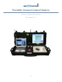
1
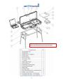
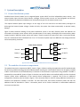
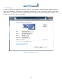
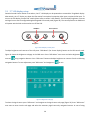
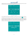
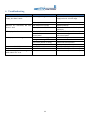
Portable Ground Control Station
A Universal Off-the Shelf Solution
User manual V 1.1
1
Contents
1
System overview ............................................................................................................................................................. 3
2
Specifications .................................................................................................................................................................. 5
3
System Description ......................................................................................................................................................... 6
4
5
3.1
Power distribution system ...................................................................................................................................... 6
3.2
The modular electronics compartment .................................................................................................................. 6
3.3
Connections ............................................................................................................................................................ 9
3.4
Switch description ................................................................................................................................................. 12
GCSsetup ....................................................................................................................................................................... 13
4.1
Electronics installation in MEC .............................................................................................................................. 13
4.2
Battery installation ................................................................................................................................................ 14
4.3
Battery charger ..................................................................................................................................................... 15
4.4
External power connection ................................................................................................................................... 15
4.5
Toughbook installation ......................................................................................................................................... 16
4.6
Foldable stand ....................................................................................................................................................... 17
Operation ...................................................................................................................................................................... 18
5.1
Power Status Display............................................................................................................................................. 18
5.2
VGA setup ............................................................................................................................................................. 19
5.3
17” LCD display setup............................................................................................................................................ 20
6
Troubleshooting ............................................................................................................................................................ 22
7
Contacts ........................................................................................................................................................................ 23
8
User manual version history ......................................................................................................................................... 23
9
References .................................................................................................................................................................... 23
2
1 System overview
Thank you for purchasing UAV Factory’s portable ground control station. UAV Factory’s off-the-shelf portable Ground
Control Station (GCS) is a flexible and universal solution for controlling unmanned vehicles and payloads. The general
overview of the GCS is given in Figure 1.
The GCS can be configured to control unmanned aircraft vehicles (UAV), ground robots, bomb disposal robots, remotely
operated vehicles (ROV) and other robotic devices. The GCS can also be configured to control and monitor other
measurement and sensing equipment.
Based on Panasonic’s field proven CF-31 Toughbook(1), the GCS has additional 17’’ sunlight readable touch screen
display, advanced power distribution system with hot-swappable dual batteries and status monitoring features. The GCS
is housed in a military grade rugged, lightweight case which makes it ideal for use in harsh environments.
3
*Panasonic Toughbook CF-31 is not included with the GCS and
needs to be purchased separately from your local supplier
Figure 1 Portable ground control station system overview
4
2 Specifications
Mechanical Specifications
Dimensions
Weight (excl. Panasonic Toughbook CF-31)
Environmental protection
Operating temperature
Electronics compartment dimensions
Mounting base
Accessory bag internal dimensions
Case features
Computer mounting type
Electrical Specifications
DC input
Battery type
Battery Capacity
Battery Operation time
Connections (all routed to Panasonic CF-31)
Connections to 17” display
DC power output 1
DC power output 2
Antenna pass-through
Computer Specifications (not included with GCS)
Model
Durability
Display Type
Brightness
17” Display Specifications
Display Type
Brightness
Touchscreen type ( optional)
1000 x 420 x 170 mm
18.9 kg
IP66 when closed
-20 to +70 °C (if equipped with wide temperature display)
320 x 270 x 80 mm
M4 threaded mounting grid, 45 mm pitch, aluminum mount kit included
220 x 160 x 70 mm
Rugged plastic case, side handles, carry handle, wheels, pressure purge valve,
shoulder strap (optional)
Docking
10 – 32 VDC
Over-voltage protection, reverse polarity protection
Lithium Ion
108 Wh
2 hours (typical)
2 serial (RS-232), 5 USB, 2 Ethernet, 1 Composite Video in (IMPERX video
device needed), 1 Microphone in, 1 Audio out, PCMCIA slot, HDMI
Composite Video (Optional), external VGA input ( Optional)
12V 5A fused, 50 W
12V 5A fused, 50 W
Two 50 Ohm antenna pass-through to upper lid
SMA-RP termination, RG 142
Panasonic Toughbook CF-31 ( all specifications as per manufacturer
datasheets)
MIL-STD-810G & IP65 certified (6' drop)
13.1" XGA touch screen LED 1024x768
1100 nits
17 " TFT 1280 x 1024 (SXGA)
Optional touch screen
Optional AR glass
1400 nits
Resistive
5
3 System Description
3.1 Power distribution system
Portable Ground Control Station has an integrated power system which has three independent power sources - one
external power input and two Lithium battery cartridges. Allthree power sources are interchangeable and GCS will
switch automatically between availablesources, with preference given to the external power input.
The required external power input voltage is in the range of 10 to 32 Volts DC.In case both battery cartridges are
discharged and external power voltage is below 10 Volts, the system shuts down automatically to prevent battery
damage.
Figure 2 shows schematic drawing of the power distribution system in the GCS. External power and batteries are
connected to the power source selector which provides power to the Laptop, LCD display and to two auxiliary power
outputs located in MEC.Each power source and output is fused to protect the system from short circuit and overload;
fuses are marked with blocks numbered from F1 to F7. The external power input has additional overvoltage protection
and reverse polarity protection.
Power Source Selector
F3
LCD
External
F7
F2
DC OUT 1
Battery 1
F6
F1
DC OUT 2
Battery 2
F5
F4
Laptop
Figure 2 Power distribution diagramofModular Electronics Compartment
3.2 The modular electronics compartment
The modular electronics compartment (MEC), shown in Figure 3 allows installing the application-specific hardwareinside
the GCS.Using theM4 mounting grid and included standard mounting kit, most hardware devices can be quickly installed
in MEC. Circuit boards can be installed directly on the base of the electronics compartment using standoffs. The MEC is
protected by a removable lid, shown in Figure 4. Once the user-specific devices are installed in MEC, the lid is closed and
remains closed, unless modification to the internal device configuration is required. The lid has an additional
configurable connection panel as shown in Figure 4. This connection panel is used for routing additional connections or
switches from equipment installed in the MEC. The GCS comes with three blank connection panels and with the
additional label set described in Table 1. Connection panels can be further machined to accommodate additional
connectors and switches.
6
User serviceable fuses
Dual antenna
pass-through
M4 Mounting Base
Figure 3 Layout of the modular electronic compartment.
Connection panel
Removable lid
Figure 4 MEC protection lid with configurable connection panel.
Two SMA-RP terminated antenna pass-through cables (Figure 3) can be used to connect the SMA-RP antennas in the
upper lid to the hardware devices located in the modular electronics compartment. Alternatively, antenna connectors
can be located on the user-configurable connection panel as shown in Figure 4.
If Omni-directional antennas are used, it is convenient to use the integrated antenna pass-through. If antennas need to
be routed outside the GCS, such as to an antenna mast or tracking antenna, it is more convenient to use the antenna
connections located directly on the connection panel.
7
Table 1 Label set description
Label
Label Description
ANT 3
Antenna Connection
ANT 4
Antenna Connection
GPS
GPS connection
RC
RC transmitter connection
DC
DC OUT 1
DC
DC OUT 2
USB
Ethernet
|O|O| 1
VIDEO IN
COM1 connection
Composite video connection
8
3.3 Connections
Ground Control Station is designed to provide a complete set of connections for electronics located inside the MEC.
There are three groups of electrical connections in the GCS (Figure 5). Group 1 is intended for external device
connectionand features one serial (RS-232) port, one microphone in, one Audio out and one USB. One VGA input for the
17” display can be optionally installedin the GCS. This option allows users to switch between the VGA input and the
Panasonic Toughbook.
Group 2 is located inside the MEC and is used for connecting application specific hardware to the GCS. Group 2features
one USB, one serial (RS-232), one Ethernet, one Composite Video (Video In 1) and two power outputs. Please note that
for capturing composite video on the Panasonic CF-31, the IMPERX VCE-PRO capture device is needed. An optional
Composite Video (Video In 2) can be factory installed to provide direct connection to the 17” display. The overview of
Group 1 and Group 2 connectors is given in Figure 6.
Additional two USB ports and one Ethernet are accessible in Toughbookitself - these connections are marked as Group 3
in Figure 5.
Group 3
USB 4
Group 1 (EXTERNAL)
17” LCD
Toughbook
USB 5
USB 2
RS-232 (Com 2)
Ethernet 2
Touchscreen
VGA IN (Optional)
VCE-PRO
Capture
VGA switch
(Optional)
Microphone in
Audio Out
Group 2 (MEC)
USB 1
Docking station
Ethernet 1
RS-232 (Com 1)
Video In 1*
Video In 2**
USB 3
Figure 5 Communication diagram.
* IMPERX VCE-PRO capture device is needed.
** Video input connected directly to the 17” display (optional).
9
Figure 6 Group 1 and Group 2 connectors overview.
10
External power connector is the XLR type connector which is located in the top right corner of the MEC (Figure 6). The
external connector pinout is given in Figure 7.
Modular electronics compartment provides two power outputs for application specific electronics, marked as ‘DC OUT 1’
and ‘DC OUT 2’, as shown in Figure 6. Each output provides up to 50 W of continuous power for internal electronics.
Figure 8 shows power output socket polarity diagram.
+ Vs
GND
NC
Figure 7 External power socket pinout
GND
+ VCC
Figure 8 Power output socket polarity diagram
11
3.4 Switch description
The ground control station has five switches on the control panel as shown in Figure 9. Each switch is labeled and has
two positions- “ON” and “OFF” respectively. Switch descriptions are given in Table 2. Additional switch is factory
installed on the control panel if optional VGA input is integrated in the GCS.
Figure 9 Control panel
Table 2 Switch description
Switch name
MAIN
LCD
DC OUT 1
DC OUT 2
PC
VGA (Optional)
Description
Main power switch. Turns on the GCS.
Turns on the 17”LCDdisplay.
Turns on power supply ‘DC output 1’ in MEC
Turns on power supply ‘DC output 2’ in MEC
When switch is “ON”,theToughbook is powered from
the GCS’s power supply. When switch is
“OFF”,theToughbookispoweredfrom its internal
battery.
VGA source selection for the 17” display. When “PC”
is selected, the display is connected directly to
Toughbook’s VGA and acts as ‘extended display’.
When “EXT” is selected, the display is connected to
the external VGA source.
12
4 GCSsetup
4.1 Electronics installation in MEC
The MEC lid can be opened by removingfour screws as shown in Figure 1. Application specific electronicscan be installed
into the modular electronics compartment using M4 mounting grid and included standard mounting kit. Mounting kit
includes 6 mounting brackets, 1 meter of 20mm Nylon webbing and 12 plastic slides.Place electronics in the MEC and
attach it with the Nylon webbing to the mounting brackets. Use supplied M4 screws to attach mounting brackets to the
MEC mounting grid. MEC has a suite of connections dedicated for application-specific electronics (please refer to section
3.4).
The example of application specific electronics installation is shown in Figure 10 and Figure 11. Figure 10 shows Procerus
Technologies Kestrel autopilot (2) communication module installation. The module is connected to the DC OUT 1 power
output which provides 12 V supply. The autopilot communication module uses ANT 1 pass-through connection for
antenna and COM 1 for serial connection to Toughbook.
Figure 11 shows typical Kestrel autopilot communication module installation with Rotoconcept’s digital video receiver
(3). In this configuration, video receiver uses ANT 1 and ANT 2 pass-through coaxial cables, DC OUT 2 power source and
Ethernet connection for communication with Toughbook. The Procerus autopilot module is powered from DC OUT 1,
and connected to COM1 serial. Antenna connectorislocated on the configurable panel on the top of the MEC protection
lid.
Figure 10 Example of hardware mounting inside MEC using adjustable aluminum mounts
13
Figure 11 Example of hardware installation in MEC for an unmanned aircraft vehicle
4.2 Battery installation
Ground control station uses two COTS Lithium-Ion MAKITA BL1830 batteries (Figure 12). Use only original 18V BL1830
MAKITA batteries (4). To remove the battery push the release button as shown in Figure 12 and pull the battery
cartridge away from the mount.
Thebatterycartridgesand external power supply can beremoved or connected any time during normal operation-the
power system automatically controls power source selection. The external power is a priority source.
Figure 12 Battery installation
14
4.3 Battery charger
GCS comes with the standard MAKITA charger (Figure 13) for the BL1830 batteries. Charging time for one battery is
approximately 30 minutes. Both 240 VAC and 110 VACcharger versions are available. The 12V DC charger version can be
purchased separately.
Figure 13 MAKITA battery charge
4.4 External power connection
GCS comes with the AC/DC adapter (Figure 14) which is used as external power source from 110 – 240 VAC mains
supply. When external power is connected, the LED which is located near the connector should light green.
Figure 14 AC/DC power adapter
15
4.5 Toughbook installation
The GCS has an integrated CF-31 Toughbook docking station.The docking station is also compatible with the CF-30
Toughbook.
Before installing the Toughbook, insure that protection lid on the back side is opened (Figure 15). Install the Toughbook
into the docking station as shown in Figure 16.Once the Toughbook is located in the docking station, the docking handle
needs to be engaged as shown in Figure 16. To remove the Toughbook from the GCS, first disengage the docking handle
and then remove the Toughbook.
Figure 15 Protection lid is opened
Figure 16 Toughbook docking
16
4.6 Foldable stand
The optional foldable stand is availablefor the GCS. Place the GCS on the top of the stand as shown in Figure 17 and
attach it to the stand using two clamps from both sides.
Figure 17 Foldable stand attachment
17
5 Operation
To turn on the Ground Control Station turn on the “MAIN” switch on the control panel (see Figure 9 for details).All GCS
power parameters are displayed on a dedicated display located in the upper part of the GCS (Figure 1).
5.1 Power Status Display
The power status display shows the GCS power status as shown in Figure 18.The following parameters are displayed on
the power status display: the total system power, internal temperature, external power voltage and battery voltage.If
system is running on batteries, the display shows “arrow” above the appropriate battery symbol as shown in Figure
18.Power status symbol description is given in Table 3.
Ps
19W
Ts
21°C
DC
LOW
17.2V
19.7V
30%
100%
BAT1
BAT2
Figure 18 Power status display
Table 3 Power status symbol description
Label
Ps
Ts
DC
BAT1
BAT2
Description
System total power in Watts.
Internal board temperature in Celsius.
External power voltage. Displays “LOW”
when voltage is below 10 Volts.
Battery 1 status. Upper value shows battery
voltage. Lower value shows remaining
battery capacity
Battery 2 status. Upper value shows battery
voltage. Lower value shows remaining
battery capacity
18
5.2 VGA setup
In order to configure the Toughbook connection to the 17” LCD, navigate to Screen Resolution window as shown in
Figure 19 for Windows 7. Make sure that Toughbook is docked and 17” LCD is switched on as well as VGA switch
(optional) is in “PC” position. Set 1280 x 1024 resolution for second display and select “Extend these displays” in the
multiple display bar. Click “Ok” to save changes.
Figure 19 Second display setup screen
19
5.3 17” LCD display setup
Oncethe Ground Control Station is turned on, the 17” LCD display can be powered on to extend the Toughbook display.
Alternatively, the 17” display can show the information from optional composite video input or optional VGA input. To
turn on the LCD display, usethe“LCD” switch (please refer to section 3.4 for details). The LCD display brightness, contrast
and signal source can be configuredusingtheintegrated LCD control panel (Figure 20). The control panel has an additional
LCD power switch which can be used to turn off the LCD.
OSD Menu
Power indicator
Navigation
LCD Power
Figure 20 LCD display control panel
To adjust brightness and contrast of the LCD press “OSD Menu” (On Screen Display) button on the LCD control panel.
Figure 21 shows the brightness sub page in the OSD menu. Press “OSD Menu” once more and select brightness
contrast
or
using navigation buttons. Press “OSD menu” button and adjust brightness or contrast from 0 to 100 using
navigation buttons. To save adjustment press “OSD menu” and navigate to
for exit.
Figure 21 Brightness sub page
To select the signal source press “OSD menu” and navigate to the signal source sub page (Figure 22). Press “OSD menu”
once more to enter into the sub page and select the necessary signal source by navigation buttons. In case of using
20
Toughbook VGA output or external VGA (optional) select VGA source. In case of using composite video source (Video
input 2) select AV source. Press “OSD menu” to save changes and exit from the sub page.
Figure 22 Signal source sub page
The color adjustment should be done when Toughtbook is connected for the first time to the LCD. Press “OSD menu”
and navigate to the color settings as shown in Figure 23. Select the automatic color adjustment
and press “OSD
menu” button. Make sure that Toughbook is connected to the LCD and PC switch is “on” before using the color auto
adjust. This function will improve image quality but some minor flickering can be still observed on the 17” display while
Toughbook is charging the internal battery. This is common issue for the external display connection through the
docking station via the VGA. High charging current goes through the same docking connector as VGA signal.
Figure 23 Color settings sub page
21
6 Troubleshooting
Problem
Possible reason
GCS is connected to external power Not enough voltage
supply, but doesn’t work.
External power fuse is blown
Batteries are connected, but GCS Both batteries are empty
doesn’t work
Battery fuses are blown
Solution
Connect batteries or appropriate power
supplyinthe 10 – 32 VDC range.
Check fuse F1. Replace if necessary.
Replace batteries
Check fuses F2 and F3. Replace if
necessary.
17” display doesn’t work
LCD display fuse is blown
Check fuse F7. Replace if necessary.
LCD was switched off on the Turn on LCD using power button on the
control panel
LCD control panel
17” display shows “No signal”
Dock handle is not engaged
Check that Toughbook is docked.
Wrong VGA configuration
Refer to section 0.
VGA switch position is wrong
Check VGA switch position
Wrong signal source
Refer to section 0.
No power at DC OUT 1.
DC OUT 1 fuse is blown
Check fuse F5. Replace if necessary.
No power at DC OUT 2.
DC OUT 2 fuse is blown
Check fuse F6. Replace if necessary.
No power output to the Toughbook Fuse is blown
Check fuse F4. Replace if necessary.
when switch “PC” is on.
22
7 Contacts
Please use the following information to contact UAV Factory:
UAVFACTORY LTD.
24A-52 Ganibu Dambis
Riga, Latvia, LV1105
Tel: +371 29119398
Email: [email protected]
8 User manual version history
Version
1.0
1.1
Comments, Updates
Date
First manual version for Portable Control 03.06.2012
Station
Added note regarding the 17” display and 07.23.2012
VGAsetup
Author
AG
AG
9 References
1. Panasonic. [Online] http://www.panasonic.com/business/toughbook/fully-rugged-laptop-toughbook-31.asp.
2. Procerus Technologies. [Online] http://www.procerus.com/index.php.
3. Rotoconcept Robotics. [Online] http://www.rotoconcept.com/.
4. Makita BL1830. [Online] http://www.makita.com.au/products/lxt/lithium-ion/item/lithium-ion/bl1830-18v-li-ionbattery?Prodid=.
23