1
file:///D|/McCalla/aifmdocs/aifm_toc.htm
Home
Application Integration Framework Manual
Table of Contents
Note: All REDLINE sections are incomplete and/or deferred to later Builds.
SECTION
TITLE
PAGE
List of Tables
vi
List of Exhibits
viii
Introduction and Overview
ix
1.0
AWIPS Architecture
1-1
1.1
System Hardware Architecture
1-1
1.2
Major System Software Components
1-1
1.3
Input and Output Devices
1-2
2.0
Local Applications Development (non-D2D)
2-1
2.1
Common Desktop Environment (CDE)
2-1
2.2
Software Tools
2-2
2.3
Setting up a Local Development environment
2-4
2.3.1
Local Development Host
2-5
2.3.1.1
Locally Attached non-AWIPS Platforms
2-6
2.3.1.2
Data Server
2-6
2.3.1.3
Applications Server
2-6
2.3.1.4
Workstation
2-6
2.3.1.5
LAN and CPU Considerations
2-6
2.3.2
Local Development User Accounts
2-7
2.3.3
Local Development User Resources
2-8
2.3.4
Local Development Directory Structure
2-8
2.3.5
CPU Allocation Control
2-9
2.3.6
Controlling Permissions
2-9
2.3.7
Operating System
2-10
file:///D|/McCalla/aifmdocs/aifm_toc.htm (1 of 6)2/15/2007 9:30:17 AM
file:///D|/McCalla/aifmdocs/aifm_toc.htm
2.3.8
Network Information Services (NIS)
2-11
2.3.9
Informix dbspaces
2-11
2.3.10
Wide-Area Network
2-11
2.3.11
Disk
2-11
2.3.11.1
Disk Allocations
2-12
2.3.11.2
System File Information
2-12
3.0
Coding and Documentation Guidelines
3-1
3.1
Software naming conventions
3-1
3.1.1
Name Lengths
3-2
3.1.2
Public API Function and Subroutine Names
3-2
3.1.3
Number/Naming of Subdirectories
3-3
3.1.4
Symbol Names and Restrictions
3-3
3.1.5
Accommodating Backup/Failover: Floating names and addresses
3-5
3.2
High Level Languages
3-5
3.2.1
Allowable C and FORTRAN extensions and features
3-5
3.2.2
Inter-Language Communication
3-9
3.2.3
Source Code Compilation
3-9
3.2.3.1
To compile C code under the gnu C++ compiler
3-9
3.2.3.2
Compiler Flags
3-10
3.2.4
X-Windows System Libraries
3-10
3.3
Scripting Languages
3-11
3.3.1
Tcl/Tk
3-11
3.3.2
Shell Scripts
3-12
3.4
Environment Variables
3-12
3.5
Shared and Archive Libraries
3-13
3.5.1
Description
3-13
3.5.2
Recommendations for Use
3-14
3.6
Error Logging and User Notification
3-15
3.7
Internal Documentation
3-17
3.7.1
Prologues and Source Control
3-17
3.7.2
Header Files and Locations
3-18
3.7.3
Standard Header Files
3-18
3.8
External Documentation
3-19
3.9
Input, Output, Display, and Printing
3-19
4.0
Data Management and Access
4-1
4.1
Data Storage/Access Packages
4-1
file:///D|/McCalla/aifmdocs/aifm_toc.htm (2 of 6)2/15/2007 9:30:17 AM
file:///D|/McCalla/aifmdocs/aifm_toc.htm
4.1.1
Flat files
4-3
4.1.1.1
NetCDF
4-3
4.1.1.2
Plotfiles
4-6
4.1.1.2.1
DataKeys, DataAccessKeys
4-6
4.1.1.3
WSR-88D Radar Products
4-6
4.1.1.4
Local Data Files
4-6
4.1.2
Informix
4-7
4.1.2.1
The dbaccess utility
4-7
4.1.2.2
Informix ESQL/C
4-8
4.1.2.3
Informix Databases
4-8
4.1.2.3.1
Text Product Database
4-8
4.1.2.3.2
ADAP²T (Digital Forecast) Database
4-8
4.1.2.3.3
Hydrological Database
4-9
4.1.2.3.4
Verification and Climate (hmdb) Database
4-9
4.1.3
Data on a Remote AWIPS
4-9
4.1.4
External Data
4-9
4.1.5
Where and How to Access Data Sets
4-10
4.1.6
Data Inventory Methods
4-11
4.1.7
Time and Date Conventions
4-12
4.1.8
Data Access Controls
4-12
4.1.8.1
Informix Concurrency Controls: Database Locks
4-13
4.1.9
Purging
4-13
4.2
Data Classes
4-13
4.2.1
Aircraft observations
4-13
4.2.2
Grids
4-14
4.2.2.1
Naming conventions for grid directories and files
4-14
4.2.2.2
Organization of netCDF grid filesm
4-15
4.2.2.2.1
Global attributes
4-15
4.2.2.2.2
Dimensions and coordinate variables
4-16
4.2.2.2.3
Variables, with their dimensions and attributes
4-18
4.2.2.2.3.1
Grid variables with their companion attribute variables
4-18
4.2.2.2.3.2
Variables representing overall file characteristics
4-21
4.2.2.3
Other supporting files
4-22
4.2.2.4
Existing software (APIs) for reading netCDF grid files
4-23
4.2.2.5
Existing software (APIs) for writing netCDF grid files
4-33
4.2.3
Point Data
4-34
4.2.3.1
METAR Data
4-34
4.2.3.1.1
File naming conventions
4-34
file:///D|/McCalla/aifmdocs/aifm_toc.htm (3 of 6)2/15/2007 9:30:17 AM
file:///D|/McCalla/aifmdocs/aifm_toc.htm
4.2.3.1.2
Organization of files
4-34
4.2.3.1.3
Supporting files
4-37
4.2.3.2
RAOB Data
4-37
4.2.3.2.1
File naming conventions
4-37
4.2.3.2.2
Organization of files
4-38
4.2.3.2.3
Supporting files
4-40
4.2.3.3
Lightning Data
4-40
4.2.3.3.1
File naming conventions
4-40
4.2.3.3.2
Organization of files
4-40
4.2.3.3.3
Supporting files
4-41
4.2.3.4
Wind Profiler Data
4-41
4.2.3.4.1
File naming conventions
4-41
4.2.3.4.2
Organization of files
4-41
4.2.3.4.3
Supporting files
4-42
4.2.3.5
Marine Report Data
4-43
4.2.3.5.1
File naming conventions
4-43
4.2.3.5.2
Organization of files
4-43
4.2.3.5.3
Supporting files
4-45
4.2.3.6
LDAD (Local Data Acquisition and Dissemination)
4-46
4.2.3.6.1
File naming conventions
4-46
4.2.3.6.2
Organization of files
4-46
4.2.3.6.3
Supporting files
4-55
4.2.3.7
Model Soundings
4-55
4.2.3.7.1
File Naming conventions
4-55
4.2.3.7.2
Organization of files
4-55
4.2.3.7.3
Supporting files
4-55
4.2.3.8
Reading and writing to point data files
4-55
4.2.4
RADAR Products
4-57
4.2.4.1
Naming conventions for image directories and files
4-57
4.2.4.2
Radar Text Products
4-62
4.2.4.3
Radar product data format
4-63
4.2.4.4
AWIPS APIs for radar product processing
4-63
4.2.4.4.1
Radar Data Access
4-64
4.2.4.4.2
Radar Data Processing APIs
4-64
4.2.5
Satellite imagery
4-66
4.2.5.1
Naming conventions for image directories and files
4-66
4.2.5.2
Organization of netCDF image files
4-68
4.2.5.2.1
Global attributes
4-70
file:///D|/McCalla/aifmdocs/aifm_toc.htm (4 of 6)2/15/2007 9:30:17 AM
file:///D|/McCalla/aifmdocs/aifm_toc.htm
4.2.5.2.2
Dimensions and coordinate variables
4-70
4.2.5.2.3
Variables, with their dimensions and attributes
4-71
4.2.5.3
Other supporting files
4-71
4.2.5.4
Software APIs for netCDF image file I/O
4-71
4.2.6
Satellite soundings
4-75
4.2.7
Text Database
4-77
4.2.7.1
Text Product Identifiers
4-78
4.2.7.2
Supporting files
4-78
4.2.7.3
Text Database I/O APIs
4-78
4.2.8
Digital Forecast Data
4-81
4.2.8.1
Grids
4-81
4.2.8.2
Zone DFM
4-81
4.2.8.3
Station DFM
4-81
4.2.8.4
IFP Database Access, APIs
4-81
4.2.9
Verification Data
4-81
4.2.9.1
Public Format, Content
4-81
4.2.9.2
Aviation Format, Content
4-81
4.2.9.3
Marine Format, Content
4-81
4.2.9.4
Hazardous Weather Format, Content
4-82
4.2.9.5
Fire Weather Format, Content
4-82
4.2.9.6
Hydrologic Format, Content
4-82
4.2.9.7
Verification Database Access, APIs
4-82
4.2.10
NCEP (REDBOOK) Graphics
4-82
4.3
Site-Specific Data Sets
4-82
4.3.1
Site-Specific Static Data
4-82
4.3.2
Site Customization and Preference Data
4-83
4.3.3
Site Specific Data Formats and Locations
4-83
4.3.4
Site-Specific Data Creation and Management
4-83
5.0
Initiation of Local Applications
5-1
5.1
From a D2D Menu
5-1
5.2
From the CDE Pop-Up Menu
5-2
5.3
From CDE Icons
5-2
5.4
From the Command Line
5-2
5.5
From the crontab
5-2
5.6
HP MC/Service Guard
5-4
6.0
Product Dissemination
6-1
file:///D|/McCalla/aifmdocs/aifm_toc.htm (5 of 6)2/15/2007 9:30:17 AM
file:///D|/McCalla/aifmdocs/aifm_toc.htm
6.1
Dissemination Mechanisms
6-1
6.1.1
WAN
6-1
6.1.1.1
The handleOUP interface
6-2
6.1.1.2
The distributeProduct interface
6-3
6.1.2
LDAD
6-3
6.1.3
Asynchronous Product Scheduler (APS)
6-3
6.2
Product Archive
6-3
7.0
On-Line Resources and URLs
7-1
8.0
References
8-1
9.0
Acronyms
9-1
Appendix 1
NetCDF API examples for reading point data files
A1-1
Appendix 2
Sample output from "testGridKeyServer" to list valid values for AWIPS grid APIs
A2-1
Appendix 3
Summary of applicable data subdirectories by WSR-88D product type
A3-1
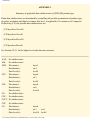
Appendix 4
External Documentation Standards for Locally-Developed AWIPS Applications
A4-1
Appendix 5
man pages for handleOUP.pl and distributeProduct CLIs
A5-1
Appendix 6
Tools to Monitor Application Performance and Resources
A6-1
Appendix 7
Suggested Format of Maintenance Documentation
A7-1
APPENDICES
ATTACHMENTS
Attachment 1
TDL FORTRAN Coding Guidelines
ATT1-1
Attachment 2
TDL C Software Implementation Conventions
52 pp.
Attachment 3
FX-ALPHA C and C++ Coding Conventions
10 pp.
Local Applications
Home Page
file:///D|/McCalla/aifmdocs/aifm_toc.htm (6 of 6)2/15/2007 9:30:17 AM
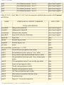
Index of Tables and Exhibits
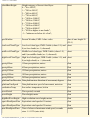
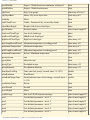
List of Tables
TABLE
DESCRIPTION
PAGE
1.3-1
Input and output device availability and locations on AWIPS.
1-3
2.2-1
Installed locations and licensing terms for Commercial, Off-the-Shelf (COTS) software provided with the
Build 4.2 version of AWIPS at the WFO and RFC.
2-3
2.3.1.5-1
Possible Server Combinations
3-16
2.3.1.5-2
Performance Factors for AS and DS
3-16
2.3.11.2-1
File System Guidelines
3-16
3.2.3.2-1
Server and Workstation Models
3-16
3.9-1
Input and Output device configurations on AWIPS
3-16
4.1-1
Storage formats and methods for the current classes of AWIPS online hydrometeorological data.
4-1
4.1.1.1-1
Correspondence between netCDF and programming language variable types.
4-4
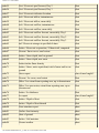
4.2.3.1.2-1 METAR data stored in a binary plotfile.
4-32
4.2.3.1.2-2 METAR data stored in a netCDF file.
4-33
4.2.3.2.2-1 RAOB data stored in netCDF files and binary plotfiles.
4-35
4.2.3.3.2-1 Lightning data stored in netCDF and binary plotfiles.
4-38
4.2.3.4.2-1 Wind profiler data stored in netCDF and binary plotfiles.
4-38
4.2.3.5.2-1 Marine report data stored in netCDF files.
4-40
4.2.3.6.2-1 Hydrological data stored in LDAD hydro netCDF files.
4-44
4.2.3.6.2-2 Automated mesonet data stored in LDAD mesonet netCDF files.
4-45
4.2.3.6.2-3 Cooperative and dial-in data stored in LDAD manual netCDF files.
4-48
4.2.4.1-1
Subdirectory name definitions for the radar product data attribute productType.
4-55
4.2.4.1-2
Subdirectory name definitions for the radar product data attribute elevation.
4-58
4.2.4.1-3
Subdirectory name definitions for the radar product data attribute resolution.
4-59
4.2.4.1-4
Subdirectory name definitions for the radar product data attribute levels.
4-59
4.2.4.2-1
Product category (NNN) identifiers for radar text products stored in the AWIPS text directory
4-59
file:///D|/McCalla/aifmdocs/aifm_table.htm (1 of 2)2/15/2007 9:36:24 AM
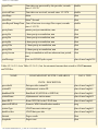
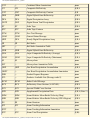
Index of Tables and Exhibits
List of Exhibits
EXHIBIT
DESCRIPTION
PAGE
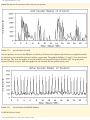
5.5-1
Arrival Pattern for Grids
A2-1
5.5-2
Arrival Pattern for METAR Products
A2-1
A2-1
Sample output lines of "testGridKeyServer -v" to list valid values for fieldID.
A2-1
A2-2
Sample output lines of "testGridKeyServer -p" to list valid values for planeID.
A2-1
A2-3
Sample output lines of "testGridKeyServer -s" to list valid values for sourceID and grid_source.
A2-1
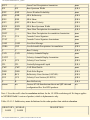
A7-1
Contents and format for PART A: PROGRAM INFORMATION.
A7-17
A7-2
Contents and format for PART B: PROGRAM FILE AND DATABASE INFORMATION.
A7-19
A7-3
Contents and format for PART C: PROGRAM CREATION AND INSTALLATION PROCEDURE.
A7-20
A7-4
Contents and format for PART D: PROGRAM EXECUTION AND ERROR CONDITIONS.
A7-21
A7-5
Contents and format for PART A: SUBPROGRAM INFORMATION.
A7-22
A7-6
Contents and format for PART B: SUBPROGRAM FILE AND DATABASE INFORMATION.
A7-24
A7-7
Contents and format for PART C: SUBPROGRAM CREATION AND INSTALLATION PROCEDURE. A7-25
A7-8
Contents and format for PART D: MANUAL PAGE FOR PROGRAMMERS.
Return to Table of Contents
file:///D|/McCalla/aifmdocs/aifm_table.htm (2 of 2)2/15/2007 9:36:24 AM
A7-26
Introduction - AIFM
INTRODUCTION
This AWIPS Application Integration Framework Manual (AIFM) is intended to assist both field and
headquarters personnel in using the AWIPS environment to develop and implement
hydrometeorological applications. An AWIPS Local Applications Working Group (LAWG) with
National, Regional, and field representation has been established to define the policy and mechanisms
under which local development and distribution of AWIPS applications may proceed. The AIFM
provides the technical guidance to the local software developer, and will be updated as often as
warranted.
A very brief overview of the AWIPS architecture is given in AIFM Chapter 1. Chapter 2 and Appendix
6 describe the AWIPS environment, development resources, software tools, and guidelines on how to
minimize the impact of local applications development on the operational AWIPS. Coding standards and
guidelines are presented in Chapter 3, and in Attachments 1, 2, and 3. Documentation standards and
guidelines are presented in Chapter 3 and Appendix 4. Chapter 4 describes the locations, content, and
methods of access to the various national hydro meteorological data received and stored on AWIPS. The
methods by which local applications may be launched is documented in Chapter 5, and the available
mechanisms for disseminating official and draft products from AWIPS are presented in Chapter 6 and
Appendix 5.
AWIPS is a complex environment in which to develop, integrate, and run applications software.
However, procedures and Application Programming Interfaces (APIs), with the associated underlying
software, are being incrementally defined to assist development. In one respect, applications that are
designed to provide a display to a user can be thought of in two categories--those that utilize the AWIPS
two-dimensional display (D2D) and those that don't. Three provisions for using D2D currently exist-Extensions, Applications, and Depictables. Extensions and Depictables are quite complex to use, and
uninformed use could easily impact the operation of AWIPS. Alteratively to using D2D, displays can be
created using standard X-Window calls, Tcl/Tk, or blt extensions to Tcl/Tk. Therefore, until safe paths
for the use of D2D can be established, no attempt should be made to integrate into D2D. When these
safe paths and system resources to utilize them become available, a separate chapter of the AIFM will
describe them.
This AIFM was written and edited primarily by SAIC/General Sciences Corpora tion, under contract to
the AWIPS Program, working with the Techniques Development Laboratory, other Governmental
organizations, and Litton/PRC, Incorporated (PRC). Some material was taken from an AIFM prepared
by PRC under Government contract for the Builds 1.0 and 2.0 architecture. Additional new material
incorporating experience gained with the current AWIPS architec ture and software was provided by
PRC.
The AIFM is a work in progress. It will be updated in some evolving and complex subject areas, and has
not yet had extensive review or use in the field. It is being provided in order to assist and guide
file:///D|/McCalla/aifmdocs/INTRODUC.htm (1 of 2)2/15/2007 9:37:37 AM
Introduction - AIFM
development of good- quality, well-documented local applications. Constructive criticism from software
developers in the field is encouraged to allow this AIFM to be improved and should be given to your
regional LAWG representative.
file:///D|/McCalla/aifmdocs/INTRODUC.htm (2 of 2)2/15/2007 9:37:37 AM
Section One of the AIFM
1.0 AWIPS Architecture
AWIPS is implemented as a client-server system. The application of client-server methods to AWIPS
facilitates the reuse of functions and provides an expandable and scalable architecture to meet the
evolving needs of long life-cycle systems.
A client-server mechanism enables multiple applications to share the services of various functions and
allows functions to be reused. For example, database services and display services are shared. Through
distribution of services, the system is expandable and scalable. This is accomplished by the ability to
move services from one platform to another, and the ability to increase, incrementally if necessary, the
computing capability needed by any one service. Both activities may be accomplished without affecting
other services or changing mission applications.
In an integrated system such as AWIPS, the multiple functional implementations need to be managed
independently of one another as much as is practical. For example, a change to the data management
function should not cause a change to the display and interaction function or a change to hydromet
processing. By separating the functionality, a degree of independence and isolation can be achieved.
Consider an application that consists of data, processing, and user interaction. It can be implemented as
one monolithic application, or it can be implemented as a set of clients that call upon services common
to user interaction and multiple applications, such as data retrieval and storage. A client/server
implementation permits services that are common to multiple applications to be made available to these
applications, without the need to develop the service for each of the applications. Such an
implementation results in reuse of services.
A client/server implementation also provides separation of client processing from server processing such
that a client can execute on a computer physically different from the one on which the service executes.
This is particularly important for AWIPS, since it is implemented with functionality executing on
different computers. For example, workstations provide the user interface with which the forecaster
interacts, data servers provide data management services to multiple applications, and application
servers process hydromet data and run background applications. Client/server also helps achieve high
availability of functions in the event a server fails by being able to switch to another server, for example,
from a data service executing on one computer to the data service running on another computer. By
constructing applications that separate functions, a switch to a backup server, due to the failure of the
primary server, is transparent to the application.
1.1 System Hardware Architecture
The current AWIPS system architecture is now documented in detail in Chapter 2 of the AWIPS System
Manager's Manual for Release 4.3 (SMM), and will no longer be included in the AIFM.
1.2 Major System Software Components
file:///D|/McCalla/aifmdocs/sec_1.htm (1 of 3)2/15/2007 9:38:22 AM
Section One of the AIFM
This section will only deal with the software components of the AWIPS hydrometeorological
subsystem, since it is these that are of direct importance to the local applications developer. Formal
documentation of the complete system software components is outside the scope of this document. For a
complete description of the system software components within AWIPS refer to the System/Subsystem
Design Description for Release 4.3.
Four major software components comprise the hydrometeorological subsystem of AWIPS: Display Two
Dimensions (D2D), AWIPS Data Analysis and Product Preparation Tools (ADAP²T), the NWS River
Forecast System (NWSRFS) at RFCs or the WFO Hydrologic Forecast System (WHFS) at WFOs, and
the Local Data Acquisition and Dissemination (LDAD) subsystem. D2D provides a system for
acquisition, processing, and display of the majority of the conventional and remotely-sensed
observations and image data, forecast model grids and graphics, and AFOS text products. The D2D
database is the source of these data sets, and consists of a combination of primarily flat file storage, with
text product storage in the Informix RDBMS. The bulk of Section 4 of this document describes the
storage formats and data access for the data sets in the D2D database.
ADAP²T provides tools for the initialization, entry, display, and editing of gridded, areal, and point
forecast data. ADAP²T acquires, processes, and stores centrally- and locally-created objective and
manual forecast guidance including Model Output Statistics (MOS), Local AWIPS MOS Program
(LAMP) guidance, and NCEP Value-Added Grids (VAG). The Interactive Forecast Preparation (IFP)
capability of ADAP²T [Limited-Use Interactive Computer Worded Forecast (ICWF) in Build 4.3] also
creates local forecast data sets in the form of a Digital Forecast Matrix (DFM) which is stored and
maintained in the Informix RDBMS, and generates textual and other official forecast products for
editing and dissemination.
NWSRFS and WHFS are a suite of applications for hydrological data analysis, data display, and
forecasting, and for maintenance of the supporting hydrological databases. The bulk of the hydrological
data sets are stored and maintained in the Informix RDBMS. Documentation for the hydrological data
sets, programming interfaces, and applications are available separately from RFCs and the Office of
Hydrology, and are not included in this document.
The LDAD subsystem supports acquisition of hydrometeorological data from local systems external to
AWIPS, and dissemination of AWIPS products to external systems by a number of mechanisms. Current
(Build 4.3) LDAD dissemination mechanisms are restricted to the LDAD Bulletin Board Service. Future
dissemination mechanisms planned for LDAD include fax, ftp, and web-based dissemination. Section 4
of this document describes the storage formats and data access for the data sets in the AWIPS side of the
LDAD database. Section 6 will include a description of LDAD dissemination mechanisms, and
references to current LDAD documentation.
1.3 Input and Output Devices
AWIPS input and output devices vary by machine and by site type (WFO or RFC). Some are shared
file:///D|/McCalla/aifmdocs/sec_1.htm (2 of 3)2/15/2007 9:38:22 AM
Section One of the AIFM
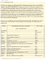
over the network, and others are available only to a specific host machine. Table 1.3-1 lists the primary I/
O devices of interest to application developers.
Table 1.3-1. Input and output device availability and locations on AWIPS.
I/O DEVICE
HOST PLATFORM(S)
WS (x5)
Color Graphics
Monitor
Two each
Color XTerm (x5)
AS (x2)
DS (x2)
LAN Resource
One each
System Console
One shared between AS's
and DS's
Keyboard
One each
One each
Mouse
One each
One each
CD-ROM
One external
drive shared
between all WS's
One shared between AS's
and DS's
One each One each
DAT Autoloader Tape
Backup
One shared
between DS's
B&W Laser Printer
(Postscript)
One
High Speed Laser
Printer
(Postscript)
One at RFCs
Color Inkjet Printer
(Postscript)
One
Internal Disk Storage
3 GB each
External Mass Storage
4 GB
each
6 GB each
(Note 1)
24 GB WFO
40 GB RFC
Note 1: On the DS, a 300 MB partition will be set up for local applications development, and a 420 MB
(WFO) or 1200 MB (RFC) partition will be set up as user space. Release 4.3 introduces a 990 MB
partition set up for local application data (see Section 2.3.3).
file:///D|/McCalla/aifmdocs/sec_1.htm (3 of 3)2/15/2007 9:38:22 AM
Section two of the AIFM
2.0 Local Applications Development (non-D2D)
This section describes the software tools and the software development environment at AWIPS WFO
and RFC sites. It gives guidelines for setting up a local software development environment which
protects the baseline AWIPS data and software configurations.
2.1 Common Desktop Environment (CDE)
At its most basic level, the Common Desktop Environment is a graphical, window-based interface to
many of the common UNIX functions without the need to learn UNIX commands and syntax. CDE
provides a File Manager from which the user can perform functions such as copy, delete, edit, execute
files; navigate through directories; create and delete directories, and find files or files with specific
contents. CDE has its own text editor with print option capability, or can be reconfigured to substitute
the text editor of your choice; a terminal window for the UNIX-capable; a print manager for printer
setup and print job management; an e-mail application; a Help Manager for online help; a calculator,
man page viewer, appointment calendar, and icon editor; and many other tools and utilities.
CDE has implemented a concept of workspaces, which is another level up from the concept of having
multiple windows on the screen. Windowing gives you the capability of having several windows open
on the screen at the same time, with the ability to switch between the single active window and the
inactive windows. Workspaces, in essence, give you the capability of having several screens within one
monitor, each able to containing its own set of multiple windows, with an ability to instantly switch
between screens. The primary difference between windows and workspaces is that only one workspace
is viewable on a monitor at any time--they can't be tiled or overlaid, i.e., they aren't windows-withinwindows.
In a practical sense, workspaces allow you to keep your screen from getting too cluttered when you need
to have several windows open and need to switch between them, or can allow you to organize related
windows into groups contained within their own separate workspaces. Multiple workspaces don't give
you more computing power, more memory, or multiple host machines--you only get a convenient way
of having many windows open simultaneously on the same monitor with less screen clutter.
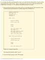
Another powerful feature of CDE is the Create Actions capability. Create Actions allows you to
associate an icon with a UNIX command or script, and to have the command run in a newly-created
terminal window, or have an application initiated by the command in the action run in a window of its
own creation. The command line you enter in the Create Actions menu allows you to enter placeholders
for input files to be acted on by the command. The power of the placeholder is that it allows you to
select a file icon from the file manager window with the mouse, drag it on top of the Action's icon, and
the command in the action will be executed on the file.
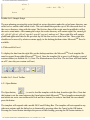
As an example, let's say you've found a non-copyrighted, freeware application to display a WSR-88D
file:///D|/McCalla/aifmdocs/sec_2.htm (1 of 14)2/15/2007 9:39:21 AM
Section two of the AIFM
Echo Tops product in pseudo-3-dimensional form in an X window, but don't have the time learn how to
write a GUI to inventory and select the products from the AWIPS database and fire up the application.
You could set up an action to run the application from the command line with the placeholder for the
Echo Tops product file as an argument. To bring up the display, you would simply open a File Manager
window and change to the AWIPS data subdirectory that holds the Echo Tops product data files
(conveniently named by date and time), select and drag the file icon for the desired time over on top of
the application's Action icon, and bingo, the application runs and up comes a window with the 3-D
display of the selected Echo Tops product.
In its initial configuration, CDE will be set up on the WFO/RFC workstations in a minimal configuration
with named workspaces for D2D (display and analysis package) and other packages. Other than
workspace switching, few or none of the CDE tools or applications will be available while the
workstation is logged in to the operational account. To gain access to the full CDE capabilities at the
workstation, it will be necessary to log out of the operational account on the workstation, and log back in
to the user or developer accounts. The System Manager will have to configure CDE for these accounts
to make available whatever tools are needed by users or software developers.
Depending on local needs, CDE workspaces and applications may be configured differently at different
sites by the System Manager. Also, the locations of applications within workspaces is a matter of
convenience and standardization more than an system-enforced limitation. At any time, any active
window can be copied or moved to another workspace, which gives the user a great deal of flexibility in
their work preferences.
This section is just an overview of CDE, covering major items of interest. Detailed information can be
found on your workstation in the online help documents included with the CDE installation, which can
be accessed from (what else!) the CDE Help Manager facility.
2.2 Software Tools
Each WFO and RFC site is provided with a basic set of Commercial, Off-The-Shelf (COTS) software to
support system management and maintenance, and local application development. The installed COTS
packages include the following:
●
●
HP-UX Operating System, includes:
- Common Desktop Environment (CDE) and associated tools
- vi text editor
- Source Code Control System (SCCS)
- make utility
- xdb and adb debuggers
- m4 macro preprocessor, for all languages
- others, see Table 2-3 of Programming on HP-UX
HP-UX ANSI C Compiler
file:///D|/McCalla/aifmdocs/sec_2.htm (2 of 14)2/15/2007 9:39:21 AM
Section two of the AIFM
●
●
●
●
●
●
●
●
●
HP-UX FORTRAN Compiler
HP DDE Debugger (C/FORTRAN)
X-Window System
OSF Motif
Visual Numerics FORTRAN Numerical Libraries (Statistics package)
Informix RDBMS: On-Line Dynamic Server, SQL, ESQL/C
OmniBack Backup Software
MC/Service Guard (see Section 5.6)
HP Process Resource Manager (see Section 2.3.5)
In addition to the commercial software installed on AWIPS, additional Off-the Shelf freeware packages
that can be used in local software development have been included with the system. The terms for use of
these freeware packages are generally contained in a README or other internal documentation file
included with the package. These packages include:
●
●
●
●
●
●
●
●
●
●
●
netCDF 3.4 (network Common Data Form; array-oriented data file system)
Tcl/Tk 8.0p2 (Tool Command Language and Tool Kit; scripting and GUI tools)
Perl 5.003_1 (scripting and text processing)
netCDF Perl 3.4
LDM (UCAR's Local Data Manager) (currently National Centers only)
a2ps (ASCII-to-PostScript converter, and 'pretty-printer')
BCS (Baseline Control System: code revision system using 'RCS')
RCS (GNU RCS, Revision Control System for configuration items/objects)
make (GNU make, build utility)
ispell (GNU ispell: spell checker utility)
blt 2.3 (extensions to Tcl/Tk)
A complete list can be found at the AWIPS Software Engineering web page at http://isl715.nws.noaa.
gov/awips/sw/cotsfree.html.
COTS Software Locations and Licensing
A summary of the initial installed locations of the COTS packages and the license terms for their use is
shown in Table 2.2-1. All COTS software has been placed in subdirectories under the /opt directory, and
freeware used in the AWIPS baseline is under /usr/local/freeware. Non-baseline public domain or
COTS software shall be installed in a site-controlled directory (i.e., /home/localapps) with symbolic
links from /usr/local (if necessary). Commercial or freeware products SHALL NOT be installed directly
into /usr/local or /opt since these directories are managed via the national baseline. License terms may
vary from site to site. See your local System Manager if there are questions about the COTS locations
and license terms.
Table 2.2-1. Installation locations and licensing terms for Commercial, Off-the-Shelf (COTS) software
file:///D|/McCalla/aifmdocs/sec_2.htm (3 of 14)2/15/2007 9:39:21 AM
Section two of the AIFM
provided with the Build 4.3 version of AWIPS at the WFO and RFC. Items in [] are under evaluation
and have not been finalized for inclusion.
COTS Package
Installed Location NFS Mounting Licensing Terms
1) Runtime or Development
2) # platform(s), or site
3) NFS mountable?
4) # simultaneous users
HP-UX OS B.10.20, CDE, vi
All hosts
n/a
Dev; 1 per host; NFS; 2 Users
(WS), 8 Users (DS/AS)
ANSI C Compiler
DS
Yes
Dev; DS1 and DS2; NFS; 1 User
FORTRAN Compiler
DS
Yes
Dev; Site; NFS; 1 User
Java development kit 1.12
LS
No
Dev; LS; no NFS; 1 User
DDE Debugger
DS
Yes
Dev; DS1 and DS2; NFS; 1 User
X-Window System x11R6
All HP-UX
platforms
n/a
Dev; Site; no NFS; Users n/a
OSF Motif 1.2
All HP-UX
platforms
n/a
Dev; Site; no NFS; Users n/a
Visual Numerics (IMSL)
FORTRAN Numerical
Libraries 3.0
DS
Yes
Dev; DS1 and DS2; NFS; No
User Limits
Informix On Line 7.3
DS
Yes
Dev; DS1 and DS2; NFS; 32
concurrent database connections
Informix SQL 7.2
DS
Yes
Dev; DS1 and DS2; NFS;
Development Phase Sites Only,
32 concurrent database
connections
Informix ESQL/C 7.24
DS
Netscape Fast Track Server
(includes 4.0.7 Browser)
AS, LS
No
Runtime; AS1, AS2, LS; no
NFS; 1 user
HP OmniBack II
DS
No
Runtime; Server-DS1 and DS2;
Agent-All HP-UX platforms; no
NFS; n/a
MC/Service Guard
DS; AS
No
Runtime; n/a; n/a; n/a
Process Resource Mgr.
DS/AS
No
Runtime; DS1, DS2, AS1, AS2;
No NFS; Users n/a
file:///D|/McCalla/aifmdocs/sec_2.htm (4 of 14)2/15/2007 9:39:21 AM
Dev; DS1 and DS2; NFS; 16
Users
Section two of the AIFM
As part of AWIPS site installation, a full suite of documentation is provided to the WFO/RFC for each
licensed COTS package within the AWIPS delivery.
2.3 Setting up a Local Development Environment
This section contains guidelines for the site's developers and AWIPS System Manager to set up an
environment for local application development. These guidelines necessarily lean towards the
conservative to help insure that local applications development has no adverse impact on operations. The
freedom and access that is allowed to local application developers should depend on the level of
proficiency of the individuals involved, and this can only be judged on a case-by-case basis. The
guidelines in this version of the AIFM are based on the assumption of development of stand-alone or
minimally-integrated applications. Significantly greater resources and privileges would be required for
development of D2D-integrated software, particularly those of the extension and depictable types, and
for development of IFP and WHFS modifications and additions, or applications with external system
interfaces.
General guidelines or "Rules to Live By" when making system changes:
●
●
●
Always save backup copies of files being changed (i.e., *.mmddyy, *.orig or *.old);
If a change is applicable to multiple platforms, change only one platform type at a time and
evaluate the changes impact on the overall system. This is especially true when making system
changes to DS/AS servers. If possible, do not change the Backup Server until the change is
proven to accomplish its goal (also consider operating in failover mode). By doing this, a "pure"
recovery (if needed) may be accomplished via a system disk image;
Document what/when/why the change was made.
2.3.1 Local Development Host
Local software development should be hosted on a single workstation designated by site management as
being available for development during times when it is not fully engaged in operations. The reasoning
behind the selection of the WS is that it is at the extreme end of the processing stream, unlike the AS or
DS which must serve multiple clients on a nearly-continuous basis. Also, it has the dedicated color
monitors with full graphics capability, which is essential for running software development tools and
developing display applications. Since neither the AS nor the DS have a monitor suitable for running
software development tools or graphical applications, then independent of which host machine is used
for local development, the developer must occupy a WS position to log into the development host.
Compilation, testing, and debugging on a WS should not affect the performance of the other
workstations, nor should it significantly impact their access to data and resources on the DS.
In an RFC, development of local applications and their operational execution may be performed on any
workstation. The reasoning behind this is that many staff members are involved simultaneously in
file:///D|/McCalla/aifmdocs/sec_2.htm (5 of 14)2/15/2007 9:39:21 AM
Section two of the AIFM
development tasks, operating independently from workstations in many areas of the office. Development
activity is dependent on office goals, available staff, and current hydrometeorological situations.
Adequate, flexible access to an appropriate number of workstations as defined by the local office is
essential for an RFC to effectively and efficiently perform it's overall mission. When operationally
installed, execution of local applications must occur on the workstation or server best suited to the
overall performance and efficiency of the system. Some local applications must be executed via the
CRONTAB for instance. It is the local office manager's responsibility to insure local applications
activity does not adversely affect the performance of other workstations or the servers.
The directories that contain the compilers, tools, user space, and development space are physically
located on the DS disks, but are NFS mounted and transparently available to the WS(s) on which
development is expected to be performed. A disadvantage of using remote NFS mounting is that it
slightly increases the local area network traffic during development-related file access (e.g. compilation,
testing, debugging), however, this is likely not to be significant.
The best place to run a locally developed application should be based on a number of factors:
1.
2.
3.
4.
5.
6.
Mass storage requirements
Schedule
Memory requirements
Database requirements
Degraded mode requirements
LAN and NFS traffic
2.3.1.1 Locally attached non-AWIPS platforms
There is an NWS policy which allows connecting additional hardware (e.g., a PC) to your local AWIPS
LAN. If this has been done, then an obvious place to execute locally developed applications is on these
platforms. Consideration should be given to how to exchange data between these platforms and other
AWIPS platforms if that is a requirement. The use of "rcp" has been proven to cause a lot of processes to
be initiated on the remote platform if a user with a long and complicated .rlogin or .chsrc is used. It may
be better to FTP or remote mount an NFS partition. Either of these methods, if used, shall be tested for
their impact on any operational platform. Caution should be exercised in remote mounting partitions.
NEVER mount a partition from a non-AWIPS platform onto an AWIPS server. This can cause severe
system problems if the non-AWIPS platform goes offline and leaves a stale mount on the AWIPS server.
Instead, use FTP or mount the AWIPS partition onto the non-AWIPS server.
2.3.1.2 Data Server
The DS is the best place to run applications that require a heavy use of the mass storage file system. See
paragraph 3.9.2 for discussion of file system considerations. Applications that access the database can be
run from any server or workstation, but if an application is generating a lot of short transactions versus a
file:///D|/McCalla/aifmdocs/sec_2.htm (6 of 14)2/15/2007 9:39:21 AM
Section two of the AIFM
few long ones, the DS may be the best location for the application.
2.3.1.3 Applications Server
The performance of AS1 is very critical in severe weather and is most impacted by severe weather
because of the applications running on it. For this reason, AS1 shall be avoided for running locally
developed applications. AS2 is heavily used by LAPS once an hour for about 10-20 minutes. Between
these runs, however, the CPU is relatively idle. The "ucron" and Glance utilities can be used to view this
pattern of execution.
2.3.1.4 Workstation
After locally attached non-AWIPS platforms, graphics or text workstations are probably the best choice
to run locally developed applications. If a workstation is used, it does not impact all users and should not
have an impact on the servers. If the graphics workstation is running D2D with many frames of image
data, memory swapping may become an issue and will impact the performance of the local user. If you
are going to use a workstation, use one with low usage, not the workstation at the Public or Aviation
desks.
An application running on the workstation should have its executable located on the workstation. If the
application is on an NFS partition, the application will load across the LAN (causing slower application
loads), and also will swap across the LAN. If a program does not load very often and doesn't use enough
memory to make swapping an issue, the trade off may not be significant. Future plans to increase the
disks on workstations will allow more applications to be mounted locally on workstations.
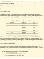
2.3.1.5 LAN and CPU Considerations
The largest percentage of LAN traffic is NFS traffic. Any locally-developed software that extensively
uses an NFS-mounted partition should be aware of the impact not only on the LAN but the server CPU
utilization. It has been determined that if large files are being written to and from NFS partitions, CPU
resources on the server can sometimes be reduced by moving the application to the server where the data
resides. Case in point: The Satellite decoder was moved from the AS to the DS. The CPU utilization
increase on the DS was essentially zero. The increase in the CPU utilization because of the Satellite
decoder move was offset by the decrease in the nfsd CPU utilization. The AS CPU utilization and LAN
utilization obviously decreased. PerfView is a good tool to see the traffic and CPU utilization of these
kind of considerations. Use of PerfView is discussed in Appendix 6.
There is also a consideration of your site's hardware baseline. Some configurations have sufficient room
on an AS while other sites may have more room on the DSs. The following table shows the different
configurations and what the relative performance factors are (with the K100 as "1"). This should just be
used for information. A better look at your system with GlancePlus or PerfView will give you a better
feel for where there are available CPU resources.
file:///D|/McCalla/aifmdocs/sec_2.htm (7 of 14)2/15/2007 9:39:21 AM
Section two of the AIFM
Table 2.3.1.5-1. Possible Server Combinations.
DSs
ASs
K220/2
D350
D380/2
D370/1
D380/2
K100
K220/4
D350
Table 2.3.1.5-2. Performance Factors for AS and DS.
Relative Performance Factors - AS
Relative Performance Factors - DS
K100
1
K220/2
2.5
K350
1
K220/4
4.8
D370/1
2.2
D380/2
3.5
2.3.2 Local Development User Accounts
Each AWIPS system will be configured with one user account on the Data Server. Other accounts
specifically for local applications development should be set up by the System Manager. The user
account for development shall be kept separate from the account(s) used in normal operations in order
that the data access and system resources used in development can be controlled. A pseudo user shall be
created to run locally developed applications. It wil be easier to track the impact of the applications
using the MeasureWare software and tools (See Appendix 6). Create a user called "localapps" and where
possible execute the local applications as that user. The developer and user accounts shall be given readonly permission to AWIPS system and data files so that no crucial data are inadvertently overwritten or
deleted. Creation of user accounts and setting of file permissions are covered in the Chapter 2 of the
AWIPS System Manager's Manual.
2.3.3 Local Development User Resources
Disk space is a major issue for local development. Developers will need a allocation of disk space for
their code and temporary data sets. The preset user account will be provided with a fixed partition of size
460 MB (WFO) or 2240 MB (RFC) of disk space. Developers will have an additional 300 MB area on
the shared (mirrored) data volumes of the DS, in /awips/dev. This area will be created as part of the site
installation procedures. Both /home and /awips/dev are shared (mirrored) data volume of the DS. The
System Manager will be able to create individual user areas under this directory.
Since these allocations are fixed, it is unlikely that a local applications developer will inadvertently "fill
up" the disk storage on the DS with a runaway application. It is up to the System Manager to assure that
file:///D|/McCalla/aifmdocs/sec_2.htm (8 of 14)2/15/2007 9:39:21 AM
Section two of the AIFM
developers and users do not obtain or use access to other areas of the disk on the DS, or to disk storage
on other machines. With 300Mb in the developer's partition, disk space will be at a premium, so either
the system administrators will have to restrict developers from exceed disk sizes by maintaining quotas,
or the site will have to develop a policy for storing and removing files.
Release 4.3 provides a new disk partition for site-specific applications and data. The partition, /data/
local, is sized at 990 MB on the shared (mirrored) data volume of the DS. The primary purpose of this
partition is for storage of local data acquired via LDAD. The partition may also used for other sitespecific purposes such as site-developed executables and scripts required for operations. The site shall
maintain these partitions below the 90% capacity level to prevent disk thrashing, as well as ITO alarms
to the NCF.
2.3.4 Local Development Directory Structure
All shared tables, executable files, etc. shall be placed into the existing areas under the /awips/dev
directory (~/data, ~/bin and ~/sharedlib). Home directories for site developed software or for special
users (e.g. fxa or informix) shall not be in baselined operational or COTS directories (e.g., /awips/fxa or /
opt/informix). All home directories for users and/or pseudo users shall reside in either the /awips/dev or /
home partitions.
Users can add paths to their local development area, or to the site's executable files, yet they shall not
modify any of the AWIPS paths. When developing new software, users may wish to have the executable
files placed into their own development area rather than overwriting an existing version of an application
that is in general use. In addition the users shall maintain their own ~/tmp space for storing temporary
data files.
AWIPS utilizes the standard UNIX configuration directory structures. For instance, when storing man
pages, these are always placed under the appropriate man/man# directory. This means that if an
application is accessible tothe site, then there shall be a /man directory in the development directory
structure for any man pages or help documentation.
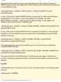
Source Code
Users shall utilize the /awips/dev/develop/src directory for storing their source code. There shall be a
global Makefile for any directories under this directory, and a configuration file for the different Make
options (MakeConfig). Any additional databases shall comply with Informix data replication
requirements (see the System Manager's Manual). All source code shall be compatible with NIS,
meaning that Internet addresses shall not be hard coded.
Executables
Once the development of a new function is complete, and has passed through the site's debugging and
file:///D|/McCalla/aifmdocs/sec_2.htm (9 of 14)2/15/2007 9:39:21 AM
Section two of the AIFM
testing cycle, the final version of the executable file(s) shall be placed in the /awips/dev/bin or /awips/
dev/sharedlib areas. When source code from /awips/dev/develop/src/dir/ is compiled the Makefile shall
place the executable file in the /awips/dev/bin area.
FXA Areas
No source code or executable code shall be placed into the /awips/fxa/bin or /awips/fxa/src areas. In
addition, since the data areas are for incoming data only, any processed data for local applications shall
be stored in the local data area.
Data Files
All configuration files and shared data files shall be stored under the /awips/dev/data directory. Users
can then share those files which will not be modified each time a local application is invoked.
Local Data
Release 4.3 provides a new disk partition for site-specific applications and data. The partition, /data/
local, is sized at 990 MB on the shared (mirrored) data volume of the DS. The primary purpose of this
partition is for storage of local data acquired via LDAD. The partition may also used for other sitespecific purposes such as site-developed executables and scripts required for operations.
Temporary Files
Local software developers should use /tmp for writing temporary files. Files left on /tmp will be purged,
but usually have sufficiently long lifetimes to be used by transient applications. Developers should not
use directories like /var/tmp and /usr/tmp.
Scheduled File Backup
OmniBack is the facility that makes a tape backup onto the archive tape,and is scheduled to run each
night. The /home and /awips/dev areas are included under the basic AWIPS backup plan. It shall not be
necessary for developers to institute any additional procedures for a guarantee that their work has been
saved to tape archive. All site-specific files shall be saved (i.e., a backup copy made) in a directory
covered by OmniBack. Common practice is to create a /home/siteID (e.g., /home/CLE) directory for
these files. This shall include saving older versions of files in a predefined format (i.e., filename.
MMDDYY).
2.3.5 CPU Allocation Control
Standard scheduling and resource allocation for processes under HP-UX are handled by the HP-UX
Scheduler. The HP-UX Scheduler has its own dynamic, automatic methods of allocating CPU resources
file:///D|/McCalla/aifmdocs/sec_2.htm (10 of 14)2/15/2007 9:39:21 AM
Section two of the AIFM
to processes, and does not allow the setting or adjustment of CPU priorities. A separate CPU resource
management tool, the Process Resource Manager (PRM), has been provided with the COTS suite on
AWIPS. PRM is a low-overhead, configurable, process scheduler which allows the System Manager to
control the dynamic HP-UX Scheduler priorities and control the amount of CPU available to users and
applications during periods of heavy CPU demand. Detailed descriptions and instructions for set-up and
use of the PRM are contained in the HP Process Resource Manager User's Guide, which has been
delivered with the HP documentation package for AWIPS.
PRM allocates CPU resources by PRM groups, which are independent of other types of groups on the
system, such as user groups. Individual users can be assigned to a PRM group, and then all their owned
processes will inherit the user's PRM resource allocations of the group. In addition, individual
applications can be assigned to a PRM group, and then the application will get the resource allocation of
its assigned group, no matter what the resource allocation is for the user who is running the application.
All system processes are initially assigned to PRM_SYS, a reserved process resource group (PRMID) of
ID number 0 (zero). If not otherwise assigned, all other user and application processes are assigned to
the OTHERS group, PRMID 1. Besides these two groups, up to 14 additional groups may be defined.
Each PRM group is assigned a percentage of total CPU, where the sum of the CPU percentages for all
defined groups must equal 100%. While competition for CPU usage is low, processes are generally
allowed as much CPU as necessary based on their resource demands. However, as total CPU usage
begins to increase towards 100%, the PRM control on CPU resources kicks in to limit processes to as
much CPU as their group has been allocated.
PRM's usefulness in controlling the resources required for local development depends on how the local
development environment is set up. If all local software development takes place on a WS wholly
dedicated to the local software developer, then the PRM will be of no use since it is only available on the
AS and DS, and since there would be no competition for resources on the dedicated WS in any event. If
local software development is performed via remote login to accounts on the AS or DS (not
recommended), then PRM can be set up to assure that local development activities do not impact the
operational servers and scheduled processes on those machines.
2.3.6 Controlling Permissions
As previously mentioned, local application developers shall be under a separate account for their
activities, and that these user accounts be given read-only permission to AWIPS system files and
operational data files. These restrictions will limit the chances that a local software development activity
will result in a corruption of a critical file in the system or the database. It is up to the individual System
Manager to determine whether to handle local developer accounts and file access permissions as a user
group, or on an individual user account basis.
Access control for data contained in the Informix RDBMS must be handled differently than data in Unix
files. Permission to directly access or modify information in tables in the database is handled through the
file:///D|/McCalla/aifmdocs/sec_2.htm (11 of 14)2/15/2007 9:39:21 AM
Section two of the AIFM
granting and revoking of privileges to individual users. Control of concurrent access to information in a
database table is handled in real time through setting and releasing database locks on specified
information in a table. Access to the Informix database is discussed in Section 4.1.6.
Since access to the text database in Informix is through a UNIX utility and not directly to the Informix
database through SQL, there is no protection to this portion of the database besides the built-in
limitations of the APIs. See Section 4.2.7.3 for cautions and guidance on use of the text database APIs.
2.3.7 Operating System
The guidance here is to NOT make any HP-UX operating system changes. This includes patches and
kernel system parameters. Patches are carefully studied by PRC for dependencies and any conflicts with
other patches, and then tested extensively with the AWIPS baseline. Patches are very hard to back out of
cleanly and SHALL NOT be applied at all. If a patch is required, the request shall be routed through
NWS HQ for consideration in a future build.
2.3.8 Network Information Services (NIS)
Changes to /etc/hosts, /etc/passwd, /etc/group and /etc/services are managed through NIS databases. All
changes to these files must be done on DS1 and propagated via NIS. Reference the AWIPS SMM
Section 3.0 for details. Modifications to "local versions" of these files are not allowed. Inconsistencies
between NIS and "local versions" will cause software to behave unpredictably and/or erratically.
2.3.9 Informix dbspaces
An Informix dbspace is a named area of allocated disk storage. In the AWIPS baseline, Informix
databases (see Section 4.1.2) are created in specific dbspaces. Informix dbspace assignments are defined
via the national baseline and therefore SHALL NOT be changed by site personnel. Loading of sitespecific databases is not allowed, except in the case of RFCs which have predefined dbspaces for this
purpose.
2.3.10 Wide-Area Network
The WAN is designed and sized for NCF monitoring and product distribution. Any other use is
unauthorized and subject to discovery and subsequent notification to the sites that are misusing the
WAN. An example of misuse is NFS mounting of another sites' disks. This should now be disallowed in
the router filtering at all sites. Another example of misuse is the export of displays across the WAN. The
NCF does this occasionally when troubleshooting a site problem, and is acceptable in limited use during
a long install, but this should NOT be done by the sites for any other reason. Use of the WAN for the
exchange of products and files shall not be done on a regular basis.
2.3.11 Disk
file:///D|/McCalla/aifmdocs/sec_2.htm (12 of 14)2/15/2007 9:39:21 AM
Section two of the AIFM
This section discusses disk allocation and system file information, and it provides guidelines that are
crucial for local software developers to consider for storing their applications.
The Mass Storage on AWIPS is redundant for reliability purposes. The mirroring of the mass storage
makes writes to the mass storage slower than writes to non-mirrored storage. If a local application is
creating a temporary file that does not need to be redundant, the best performance can be accomplished
by writing to non-mirrored storage. Volume Groups 0 and 1 (vg00 and vg01) are the internal disks and
are not mirrored; Volume Group 2 (vg02) is the mirrored mass storage device. A "bdf" command will
show you what partitions are on what disks.
As a reminder, please clean up or overwrite temporary files.
2.3.11.1 Disk Allocations
Disk allocations are defined in the Mass Storage Design document and a controlled via the national
baseline and therefore SHALL NOT be changed by site personnel. The unallocated disk space is
evaluated on a per-release basis and is intended for future use. Local software development should be
done in the /awips/dev or /home directory, using /home/localapps for common source code and
individual developers' subdirectories (e.g., /home/localapps/devname) for other items. Release 4.3
provides a new disk partition /data/local for site-specific applications and data. The primary purpose of
this partition is for storage of local data acquired via LDAD. The partition may also be used for other
site-specific purposes such as site-developed executables and scripts required for operations.
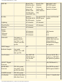
2.3.11.2 System File Information
The following table lists critical directories and files, and guidelines on their treatment by the developer
or system manager.
Table 2.3.11.2-1. File System Guidelines.
File or Directory
Guidelines and Cautions
/ (root)
All directory ownerships and permissions at the root level shall be left alone.
/.profile
/.rhosts
Changes to these files may severely impact operations of the platform.
/etc
This is a sensitive area and should be approached with caution. Be aware of
NIS-managed files and, as discussed above, any changes to NIS-managed
files MUST BE made on DS1 only.
/etc/rc.config.d
These files are especially sensitive and shall not be modified without prior
discussions with Headquarters.
file:///D|/McCalla/aifmdocs/sec_2.htm (13 of 14)2/15/2007 9:39:21 AM
Section two of the AIFM
/etc/rc.config.d/netconf This file shall only be change by the site when assigning the site-specific IP
Address to the LDAD server. This assignment is made by the
"ROUTE_DESTINATION[1]" entry. No other changes shall be made to this
file. Changes to any "[0]" entries will impact WAN access.
/var
This partition contains many dynamic operating system files. Caution should
be taken whenever files are being deleted. When freeing space in /var, files
under /var/tmp and /var/adm/crash can be deleted.
var/spool/cron/crontabs Files under this directory have been scheduled via the cron daemon. Files
shall NEVER be added/deleted from this directory, as it could have adverse
effects on the cron daemon. Proper submittal/removal of a user's cron is
through the instructions in Chapter 18 of the SMM.
/stand
DO NOT TOUCH. This area is for HP-UX kernel rebuilds.
/usr
DO NOT TOUCH. This area contains UNIX tools. Many symbolic links
exist here and critical to proper operations of HP-UX.
/opt
/usr/local
These directories are managed via the national baseline and therefore
SHOULD NOT be changed by site personnel. No products should be added/
removed from these directories. The size of these directories is evaluated
whenever a new or upgraded product is recommended for release. If sites
obtain non-AWIPS software products from HP that normally would be
installed in /opt, or public domain software that normally would be installed
in /usr/local, the installation of the package shall be in a site-controlled
directory (i.e., /home/localapps) with symbolic links from /opt or /usr/local (if
necessary).
file:///D|/McCalla/aifmdocs/sec_2.htm (14 of 14)2/15/2007 9:39:21 AM
Section Three of the AIFM
3.0 Coding and Documentation Guidelines
The material in this section is meant to be a guide to development of robust, portable, maintainable
software. The degree to which a local developer adheres to a coding style and a set of standards may be
a matter of personal choice if that code will be used only by the developer or within the office. Each
WFO, RFC, or Region may have its own set of more comprehensive software standards for software
intended for wider distribution which may apply to a locally-developed application. Suggested changes
should be provided to your regional LAWG representative to be included in future updates of this
document.
The AIFM coding and documentation guidelines are adapted from those originally defined and used for
AWIPS hydrometeorological applications development at the Techniques Development Laboratory and
PRC, and for the DAR3E system at the Forecast Systems Laboratory. Additional guidelines for
development using software tools and packages not originally part of AWIPS but used in D2D (e.g., Tcl/
Tk, C++) inside WFO-Advanced may be included in future releases of this document.
3.1 Software Naming Conventions
This section contains AWIPS guidelines for naming of files, source directories, and code symbols. The
degree to which these naming conventions need to be followed depends on the intended use for a local
application, and the history of the application. Applications which are not intended to leave the local
office or work in environments outside the core AWIPS hardware and software may not need to follow
the guidelines. The guidelines may not be practical for medium or large applications which already exist
(legacy code), and which would involve a great deal or re-engineering or modification to meet the
guidelines. Adherence to the guidelines is required for new application development which is targeted
for national or regional deployment, or which would have long lifetimes and portability to other
platforms.
Naming conventions shall be used for locally developed applications; avoid using the same (or similar)
names as already existing applications, file systems, or executables. This is especially true for common
UNIX executables and utilities like grep, more, and cat. Common extensions shall be used, such as ".
sh" for POSIX shell scripts, ".csh" for C Shell scripts, ".pl" for Perl scripts, and ".f" or ".for" for
FORTRAN applications source code, ".c" for C-language source code, and ".C" or ".cpp" for C++
source code. Locally developed applications shall be stored in a "local" subdirectory (e.g., /data/fxa/
localapps or /home/localapps) using the guidelines in Section 2.3.4. More detailed naming convention
guidance is given in the sections that follow.
3.1.1 Name Lengths
File Name Length:
file:///D|/McCalla/aifmdocs/sec_3.htm (1 of 25)2/15/2007 9:39:43 AM
Section Three of the AIFM
For portability, all file names, including programs, libraries, and the like, shall be 14 or fewer characters.
Source file names shall be 12 or fewer characters to account for SCCS prefixes, for example:
/awips/dev/develop/src/ioutil/getGrid.c - contains the getGrid() function.
/awips/dev/develop/src/grib/loadObj.c - contains the loadObj() function.
Symbol Name Length:
Symbol names are the names used within the source and object code to reference procedures and
parameters. For example, in FORTRAN, the name that follows in the PROGRAM, SUBROUTINE, or
FUNCTION statement is the symbolic name of the module, and may differ from the filename of the file
containing the source code for the module (see the above two C examples). ANSI standard name
conventions are too restrictive at 6 characters. AWIPS allows symbol names to be unique up to 31
characters.
3.1.2 Public API Function and Subroutine Names
Public and Private APIs
Public APIs are those functions and subroutines which are not unique to a single application, or which
may be used now or in the future by other applications (i.e., library routines, utility functions, services,
etc.). Private APIs are the individual functions and subroutines comprising an application and unique to
the application. It is a matter of judgement on the part of the developer as to whether a function or
subroutine developed for an application is reusable by other applications and should be treated as a
public API or utility. There is no specific symbolic or file naming convention for private APIs, although
the names should attempt to be unique to the extent possible, and the routines should be organized into
subdirectories according to Section 3.1.3.
The AWIPS public API naming convention for C is verbNoun, and for FORTRAN is in the form
VERB_NOUN. The individual public API modules shall follow the verbNoun name convention. Note
the use of case in the examples.
Example of a C prototype:
Status getGrid (Product_def the_criteria,
DBObject mySelection, float * myGrid);
Example of a FORTRAN prototype:
SUBROUTINE LOG_ERROR ( Caller, Message, Error_Level )
3.1.3 Number/Naming of Subdirectories
file:///D|/McCalla/aifmdocs/sec_3.htm (2 of 25)2/15/2007 9:39:43 AM
Section Three of the AIFM
The appropriate master directory shall be determined for each application or library, and for each source
module comprising the application or library. Each master subdirectory shall be placed under the /awips/
dev/develop/src directory. Using the example from Section 3.1.1, the public API getGrid would be
placed in the /ioutil subdirectory, under /awips/dev/develop/src:
/awips/dev/develop/src/ioutil/getGrid.c - contains the getGrid() function
The module loadObj, which is a private subroutine of a GRIB decoder, is placed in the /grib
subdirectory which holds all the private modules of the GRIB decoder application:
/awips/dev/develop/src/grib/loadObj.c - contains the loadObj() function.
All the non-utility (private) modules of an application shall reside under the master directory for the
application. For large or complex applications, as many additional subdirectories as needed in order to
organize the code may be defined under the master directory.
3.1.4 Symbol Names and Restrictions
Public Symbols (Variables, Constants, and Preprocessor Macros)
Public symbols are often declared as "extern" symbols in C, and declared in COMMON blocks in
FORTRAN. The public symbol naming convention for AWIPS is adjectiveNoun for C, and
ADJECTIVE_NOUN for FORTRAN. As with APIs, the public designation refers to symbols that are
used and known system-wide or in more than one application.
Example of C public symbol:
extern int lastToken;
Examples of FORTRAN public symbols:
INTEGER LAST_TOKEN
PARAMETER LAST_TOKEN
Exceptions
The only exception to this naming convention is static functions and variables in C. The prefix g_
notifies everyone of the scope of a C static symbol.
C Restrictions
file:///D|/McCalla/aifmdocs/sec_3.htm (3 of 25)2/15/2007 9:39:43 AM
Section Three of the AIFM
Each language has a list of standard functions provided by the standard libraries. Those names are
restricted. Additional standards committees have notified software developers about their intent to use
additional symbols (for example POSIX and ANSI C). In addition to a specific list of standard X/Open
functions and macros (see Systems Interfaces and Headers, Volume 2 of the X/Open Portability Guide,
Issue 4), ANSI C reserves for future use all symbols beginning with:
__
macro (double underbar)
_[A-Z]
macro
E[A-Z|0-9] macro
LC_[A-Z] macro
SIG_
macro
SIG[A-Z] macro
_
function
is[a-z]
function
mem[a-z] function
str[a-z]
function
to[a-z]
function
wcs[a-z] function
In addition to ANSI C restrictions, POSIX reserves for future use all symbols that end with the
following letters:
_t
_MAX
In addition to ANSI C restrictions, POSIX reserves for future use all symbols that begin with the
following letters:
B[0-9]
F_
I
LC_[A-Z]
O
O_
S_
SA_
TC
V
c_
file:///D|/McCalla/aifmdocs/sec_3.htm (4 of 25)2/15/2007 9:39:43 AM
Section Three of the AIFM
d_
l_ (lower case L)
gr_
pw_
sa_
st_
tm_
tms_
FORTRAN Restrictions
FORTRAN has a list of standard functions provided by the standard libraries, which are restricted. HPUX FORTRAN provides a number of extensions to the standard libraries, which shall also be avoided.
Refer to the HP FORTRAN/9000 Programmer's Reference, Vols. 1 and 2 for a list of HP FORTRAN
intrinsics, utilities, and system functions.
3.1.5 Accommodating Backup/Failover: Floating names and addresses
All software shall be compatible with MC/Service Guard fail-over procedures (refer to Section 5.6).
This means that when addressing the data servers and application servers from a local application, the
application process must utilize the floating IP address strategies. These would be accessed by
addressing either the data server (ds-<site>), or either application server (as1f-<site> or as2f-<site>). In
the case of a fail-over each of these addresses will be mapped to the surviving CPU, and the appropriate
packages will be restarted.
As a result, if the application uses services on the AS or DS that are protected under MC/Service Guard
(e.g., access to D2D datasets on the DS), it will still be able to transparently access those services if the
service's host machine switches to the designated backup machine. It does not imply that the local
application itself will be switched to the backup machine or restarted if it fails. The application itself will
be protected only if it is set up under MC/Service Guard, which is an uncommon scenario.
3.2 High Level Languages
Choice of Language
The language that is used for locally developed software should be based on a number of factors:
1.
2.
3.
4.
performance requirement of application,
performance impact on system,
frequency of application,
use of application.
file:///D|/McCalla/aifmdocs/sec_3.htm (5 of 25)2/15/2007 9:39:43 AM
Section Three of the AIFM
High-Level (compiled) languages are the best choice where performance of the application or
minimization of system impact is an issue. The following compiled development languages are
supported for AWIPS: C, C++, and FORTRAN. The infrastructure development is in C or C++.
Rendering components must interface with the X Window System in C, but may include calls to
FORTRAN subroutines for data processing. File I/O routines that are built on the netCDF APIs for
creating, reading, or writing netCDF data files may use their choice of the FORTRAN, C, or C++
netCDF APIs.
All C and C++ code shall be compiled with the ANSI option.
3.2.1 Allowable C and FORTRAN extensions and features
This section describes a process for bringing legacy code and new software into future versions of
AWIPS. The information provided in this chapter draws on the experiences gained from the Design,
Development, and Testing (DDT) teams, mainstream design, and prototyping efforts including
Pathfinder.
Use of FORTRAN 77 Extensions
The following is a listing of the extensions to FORTRAN 77 that are allowed. Extensions that are
anticipated to be part of the FORTRAN 90 standards are indicated (FORTRAN 90).
●
●
BLOCK and LABELED DO LOOPS (FORTRAN 90).
CYCLE statement (FORTRAN 90). The CYCLE statement is used to control the execution of
DO loops. When the statement appears in a DO loop it causes the current iteration of the DO loop
to be bypassed. The DO loop resumes execution at the next index value, for example:
DO 100 ICNT = 1,10
IF (DB_PROD(ICNT).EQ.' ') CYCLE
ZONEPRD(INUM) = DB_PROD(ICNT)
100 CONTINUE
●
DO WHILE (FORTRAN 90). The DO WHILE statement is like the DO statement except that the
DO WHILE statement uses a logical expression to control the loop, for example:
DO WHILE (DB_PROD(ICNT).NE.' '.AND.ICNT.LE.MAXZNE)
NAME = DB_PROD(ICNT)
ICNT = ICNT + 1
END DO
file:///D|/McCalla/aifmdocs/sec_3.htm (6 of 25)2/15/2007 9:39:43 AM
Section Three of the AIFM
●
EXIT (FORTRAN 90). The EXIT statement is used to control DO loop termination, for example:
DO 100 ICNT = 1,10
NCNT = ICNT + NCNT
IF (NCNT.GT.MAXNUM) EXIT
JROW(ICNT) = NCNT
100 CONTINUE
●
●
●
INCLUDE (FORTRAN 90). The INCLUDE statement allows the compiler to include and
process subsequent source statements from a specified file. Note: $INCLUDE statements are not
allowed.
IMPLICIT NONE (FORTRAN 90). The IMPLICIT NONE statement explicitly reinforces
declaration of variable names, which helps eliminate typing errors. Although explicit declaration
is encouraged for this purpose, the FORTRAN convention for implicit typing shall be followed.
SELECT CASE (FORTRAN 90). The CASE statement allows for execution of a certain block of
code based on the value of an integer, character, or logical expression, for example:
SELECT CASE (IELEMENT)
CASE(1)
ELEHDR = '12 HR POP'
CALL PROCPOP(...)
CASE(2)
ELEHDR = 'TEMP'
CALL PROCTEMP(...)
CASE(3)
ELEHDR = 'MXMN'
CALL PROCMXMN(...)
END SELECT
●
●
Data types *n declarations. Explicit statements such as REAL*8 are allowed, when needed. The
normal word length should be used when possible. Do not save memory by using INTEGER*2.
STRUCTURE and RECORDS. The STRUCTURE statement defines the type, size, and layout of
a structure's fields and assigns a name to the structure. RECORDS of the structure can then be
declared. They allow the reading of temporary flat files and help to avoid excessively long
argument lists, which detract from code readability. Mismatched argument lists are a frequent
source of bugs. However, this is another level of abstraction and should be used only when
needed. One example of when it is needed would be a long call sequence that is used many times.
file:///D|/McCalla/aifmdocs/sec_3.htm (7 of 25)2/15/2007 9:39:43 AM
Section Three of the AIFM
Use of this call sequence only once does not justify a structure. An example of the structure
statement is as follows:
STRUCTURE /EFPC_S/
CHARACTER *3 STATLIST(MAXSTA)
INTEGER ELEWARM12Z(21)
INTEGER ELECOLD12Z(21)
END STRUCTURE
●
●
ALLOCATABLE, ALLOCATE, and DEALLOCATE statements. These statements allow
dynamic memory allocation and deallocation.
Intrinsic functions. Allowable intrinsic functions that are FORTRAN 77 extensions are as
follows:
❍
❍
❍
Bit manipulation - BTEST, IAND, IBCLR, IBITS, IBSET, IEOR, IOR, ISHFT, ISHFTC,
IXOR, SHFT, MVBITS, NOT, RSHFT, XOR, ZEXT
HP-UX system intrinsic - GETARG, GETENV, IARGC, IGETARG
Miscellaneous - SIZEOF
Note: Because we are using the generic form, the variables used can be of different types (that is,
type coercion of intrinsic arguments).
For more information, see the HP FORTRAN/9000 Programmer's Guide, Chapter
●
●
●
●
●
●
Variable and subroutines names greater than 6 characters (FORTRAN 90). The limit is 31
characters.
Underscore characters in variable and subroutine name (FORTRAN 90). $ signs in character
names are not allowed.
Octal and Hexadecimal Constants. These constraints should be used where they are definitely
preferable to decimal for understandability.
Vector Library functions. These functions are allowed when they are adopted to improve
performance and should be isolated when possible. For more information see the HP
FORTRAN/9000 Programmer's Guide, Chapter 16.
Character and Noncharacter data items can share the same storage space through the
EQUIVALENCE statement (FORTRAN 90).
*RETURN. Although the alternate return is part of FORTRAN 77, it should be used sparingly.
file:///D|/McCalla/aifmdocs/sec_3.htm (8 of 25)2/15/2007 9:39:43 AM
Section Three of the AIFM
●
WHATSTR. Although not a FORTRAN 77 extension issue, this is necessary Source Code
Control System (SCCS) information, for example:
CHARACTER*100 WHATSTR
WHATSTR = "+[-] %W%"
●
List directed internal input or output, for example:
CHARACTER*20 C
WRITE (C,*) I,J,K
FORTRAN Extensions That Are Not Allowed
●
●
Dangling comments (FORTRAN 90). Dangling comments are comments at the end of a line
following an !.
ALIAS. The ALIAS statement provides a way to direct the compiler to use the appropriate
parameter passing convention to communicate with routines written in other high-level languages
such as C. A workaround is to use the + u compiler flag and pass everything as a reference. See
the HP FORTRAN/9000 Programmer's Guide, page 19-29 for more information.
●
Automatic array declaration (FORTRAN 90).
●
BYTE and DOUBLE PRECISION data type declarations.
●
Dollar sign ($) characters in variable and subroutine names (FORTRAN 90).
●
Lower case characters in a user-defined name (FORTRAN 90).
●
TAB character formatting.
●
●
●
Data initialization in a TYPE statement. A TYPE statement cannot be used to assign initial values
to declared variables.
Alternative interpretation of logical variables. Errors such as "Mixed data type assignments with
logical variables," "Comparison of logical variables in a equation," and "Arithmetic operations on
logical variable" are not allowed.
Automatic character strings. Automatic character strings are character variables whose length is
specified using a nonconstant, for example: SUBROUTINE A(C,L)
file:///D|/McCalla/aifmdocs/sec_3.htm (9 of 25)2/15/2007 9:39:43 AM
Section Three of the AIFM
CHARACTER*L C
These strings are used to implement the socket connection between ICWF routines.
●
●
The %VAL and %REF statements.
ON statement. The ON statement specifies the action to be taken after the subsequent
interruptions of a program's execution and allows for trapping interrupts. No other signaling
mechanisms are available.
3.2.2 Inter-Language Communication
Complications arise when compiling and linking programs composed of source and object modules in
different languages, for instance, calling a C function from a FORTRAN program. The most common
problems encountered when calling routines of another language are summarized in the following
paragraph. Refer to the Programmer's Guides for additional guidance.
Using C Functions in FORTRAN Subroutines and Vice Versa
For applications that must mix C or C++ with FORTRAN, remember that FORTRAN passes variables
by reference, and C/C++ passes variables by value. Also, FORTRAN uses column-major for matrices,
while C and C++ use row-major. Character strings in C are null-terminated, while in FORTRAN they
are not explicitly null-terminated. Also, in FORTRAN, strings are represented as a string descriptor
composed of an address and a length by value. The Programmer's Guides give suggestions or passing
character strings between C/C++ and FORTRAN.
Certain other restrictions apply when using C++ compiled code in a mix with FORTRAN routines, even
if the mixed routines are all C. The top level or main routine must be written in C++ or C when
compiling and linking with the C++ compiler. All FORTRAN subroutines called from code compiled by
the C++ compiler must be declared in a header file and be preceded by 'extern "C"' to prevent name
mangling by the compiler. Any header files which do not have this must be wrapped by 'extern
"C" {<headerfile.h>}' when they are included. FORTRAN libraries, such as 'vec' and 'U77', will need to
have their paths explicitly defined when including them in your load list.
3.2.3 Source Code Compilation
Two high-level language compilers are provided with AWIPS in support of local applications
development: the HP FORTRAN compiler, and the HP ANSI C compiler. Both the FORTRAN and C
compilers are capable of compiling code under the respective ANSI standards.
Beginning with Release 5.0, several of the GNU family of freeware compilers are provided. Currently,
both the gnu C and gnu C++ compilers are delivered and installed in /opt/gcc. The version of gcc used
file:///D|/McCalla/aifmdocs/sec_3.htm (10 of 25)2/15/2007 9:39:43 AM
Section Three of the AIFM
on AWIPS is 2.95.2. Official documentation is limited but many websites and user groups are available
to learn more about GNU and gcc.
3.2.3.1 To compile C code under the gnu C++ compiler
Reserved.
3.2.3.2 Compiler Flags
On most of the systems, ANSI C is delivered. It is more efficient than other options because it is
precompiled and can be optimized for the platform. When using C, there are optimization flags that are
recommended. To determine the model of the server or workstation on which you intend to run your
software, type "uname -m". Use Table 3.2.3.2-1 to determine the model.
Table 3.2.3.2-1. Server and Workstation Models
All WKs
9000/770
J210
DS
9000/819
K200
9000/859
K220
9000/861
D370
9000/871
D370
9000/820
D380
9000/809
K100
9000/821
D350
AS
When compiling use the following flags: +DAModel +DSModel - (.e.g. +DAD380 +DSD380) If you
want to make it so that your software will run on any of the platforms use +DAportable instead. This
information is documented in detail in the man page for "cc". Optimization is upward compatible but not
backward. Code optimized to run on a D series will not run on a K or J series platform.
3.2.4 X-Windows System Libraries
The X libraries are installed on the systems and are available for compiling code into either C or C++
applications. There are several X references that may be useful. Some of these were included as system
documentation:
●
Xlib documentation for C Language X Interface information
❍ HP XLIB EXTENSIONS
❍ HP XLIB PROGRAMMING MANUAL VOL 1
❍ HP XLIB REFERENCE MANUAL VOL 2
file:///D|/McCalla/aifmdocs/sec_3.htm (11 of 25)2/15/2007 9:39:43 AM
Section Three of the AIFM
●
X Toolkit Intrinsics documentation for C Language Interface information
❍ HP X TOOLKIT INTRINSICS PROGRAMMING MANUAL VOL 4
❍ HP X TOOLKIT INTRINSICS REFERENCE MANUAL VOL 5
❍ HP X WINDOW SYSTEM C QUICK REFERENCE
The latest HP documentation may be found at the following Web links:
●
●
●
●
Contents of the HP-UX 10.* (June 1999) Collection http://docs.hp.com/dynaweb/hpux10/
@Generic__CollectionView
Contents of Development Tools & Distributed Computing Collection http://docs.hp.com:80/
dynaweb/hpux10/dtdcen0a/@Generic__CollectionView
Using the X Window System http://docs.hp.com:80/dynaweb/hpux10/dtdcen0a/b696/
@Generic__BookView
X Window System C Quick Reference Guide http://docs.hp.com:80/dynaweb/hpux10/dtdcen0a/
b670/@Generic__BookView
3.3 Scripting Languages
3.3.1 Tcl/Tk
Tcl/Tk is the current language used for most of the user interfaces. See the Software Engineering
Working Group (SwEG) Freeware Page for the latest information on public domain software for AWIPS
Releases 4.3, 5.0, 5.1.1 and proposed for 5.1.2. Tcl is an interpretive tool command language with
additional utilities for scripting. Tk is the tool kit used by D-2D for creating graphical interfaces
(windows, widgets, etc.). Since Tcl is an embeddable language, it is not dependent on system resources
(doing ps's, etc.) like Perl is.
Tcl/Tk tends to utilize its own version of utilities, rather than the systems utilities (e.g., Tcl has its own
sorting utility). In many cases, a C program might suffice in application development, but it would
require the developer to write hundreds of lines of code compared to a single Tcl line. Tcl can spawn
children, as the user can use the "exec" command, but otherwise the versions seem to be self-contained.
Tcl may not perform as well as other methods. The run-time application may not be as efficient as a C
application, but the required development time for Tcl applications may be much less than that for C
programming. In one test, an application was written in Tcl by a good Tcl programmer in 10-20% of the
time it took for the same developer, also an expert C programmer, to write the program in C.
file:///D|/McCalla/aifmdocs/sec_3.htm (12 of 25)2/15/2007 9:39:43 AM
Section Three of the AIFM
For applications with the following attributes, it makes sense to use a scripting language such as Tcl/Tk:
●
●
●
●
●
●
●
the main task of the application is to integrate and coordinate a set of existing components or
applications,
the application must manipulate a variety of different things,
it must have a graphical user interface,
the application does a lot of string processing,
the functionality of the application will evolve rapidly over time,
the application is easy to extend and customize in the field,
the application must run on a diverse set of platforms.
On the other hand, for applications with the following attributes it makes more sense to use a compiled
programming language for the application:
●
●
●
the application implements complex algorithms and data structures,
execution speed is critical (e.g., the application must frequently scan datasets with tens of
thousands of elements),
the functions of the application are well defined and slow to change.
More information on Tcl/Tk can be found at:
http://www.scriptics.com/products/tcltk/
3.3.2 Shell Scripts
For most purposes, it is recommended that shell or Perl scripts not be used to implement operational
programs. Because scripts require more computing overhead and take longer to execute than similar
compiled programs, their use needs to be evaluated on a case-by-case basis. Several factors need to be
considered to decide if scripts should be used or not: frequency of execution, load on the system caused
by the program, and priority of execution of the program. If all or a combination of these factors is high
then scripts may not be the right choice for this program. Some examples of when script should be used
are: to start or stop other processes (daemon processes), installation programs, initialization programs,
localization programs, rapid prototyping, or programs that don't get executed often (e.g., not more often
than once every ten minutes).
Over the evolution of the prototype to the AWIPS baseline, a number of script-based applications have
been rewritten into compiled C or C++ and the positive impact system has been phenomenal. For
instance, the purgeAllRedbook script in R4.1 takes 14 minutes to run, uses an average of 60% of the
CPU and is responsible for approximately 7000 processes to be executed. In R4.2, this process was
included in the C language master_purge that purges everything (including the Redbook now) in less
than two minutes.
file:///D|/McCalla/aifmdocs/sec_3.htm (13 of 25)2/15/2007 9:39:43 AM
Section Three of the AIFM
Scripts have their place, however. Start and stop scripts, initialization scripts, installation scripts, and
one-shot applications are OK, as is the use of scripts for rapid prototypes. However if an application is
expected to run on a cycle, or if the frequency of the application is suspect, compiled languages are
faster and also kinder to the system.
3.4 Environment Variables
Environment variables are a way of setting and passing environment information from the Unix shell to
processes and subshells under it. Environment variables in HP-UX are discussed in a general fashion in
Chapter 11 of the manual Using HP-UX. The manner in which environment variables are set and used
depends on the shell that you are using. See the entries for the commands csh, ksh, or sh in HP-UX
Reference, Volume 1. Depending on how a local software application interfaces with AWIPS
components, it may be necessary for the application process to determine and use the value of
environment variables defined for one or more of the AWIPS subsystems (e.g., D2D, IFP, WHFS).
Among other purposes, environment variables are used in D2D to set the locations of master directories
for meteorological datasets and system-specific datasets, and to configure the local site. The system
environment variable that will most commonly be required for local application development is
$FXA_DATA, which defines the path to the meteorological data directories (e.g., /radar, /sat[ellite], /
point/METAR, /point/RAOB, /Grid subdirectories).
Environment variables for WFO-Advanced are defined in the file ~fxa/.environs, and may be locally
overridden by ~fxa/.environs.hostname. They are set at login to the operational account, or can be set
by a user by running the script ./usr/local/fxa/readenv.sh (sh, ksh, or bash), or readenv.csh (csh, tcsh, or
zsh) depending on the shell used. The environment variable $LOCAL_BIN will be added to the D2D .
environs file for Release 4.0. If the site creates applications that will tie into either D2D or the D2D
display (see Section 5.1), then the PATH in $LOCAL_BIN, which is set to /awips/dev/bin, assures that
the appropriate binary file will be found by D2D. Keep all local environment variables in the file /awips/
dev/data/rc.<SITE>, and then source this file upon login. Local environment variables shall be named
<SITE>_VAR, etc.
While in the operational account, the names and values of all the currently set environment variables can
be determined from the command line in the terminal window using the env command (from the C
shell). It may be necessary to have the System Manager access the values of environment variables if
file protections do not allow individual users to do so, or if the user is prevented access to a terminal
window from the operational account.
The environment variables for the AWIPS components will not automatically be available to developers
in their personal accounts. To use the AWIPS environment variables in a developer account, they or
their initializing scripts must be either copied to the selected shell's login script for the developer's
account, or sourced or manually entered at each session. Otherwise, their defined values must be
literally incorporated into the code or script in which they are to be used, which is an undesirable
file:///D|/McCalla/aifmdocs/sec_3.htm (14 of 25)2/15/2007 9:39:43 AM
Section Three of the AIFM
solution.
3.5 Shared and Archive Libraries
Libraries are files with collections of compiled object code that can be used in building a program. For
example, when you want to use the atan2 function in your C program, you can use the function
available in the C compiler's math library. To do so, you tell the system where to find the function by
including the math library in your program by using the #include <math.h> preprocessor directive. You
don't have to write source code or compile the atan2 function yourself--object code for the function
resides in the C math library, and it only needs to be located and linked into your program in order for
your program to use it. In a similar manner, individual developers can create libraries of related, reusable
functions, and can use libraries created by others.
3.5.1 Descriptions
Two types of libraries can exist on HP-UX: archive and shared. The linking mechanism defines the
primary difference between archive and shared libraries. In the case of an archive library function, a
complete, separate copy of the referenced function's object code is created and linked with the main
program's object code in assembly of the executable program. A program built of all archive library
object code is a complete, stand-alone executable file.
In the case of a shared library, the linker does not link a copy of the referenced object code into the
executable file, it only notes the address locations of where the function can be found. When the
program is executed, a dynamic loader looks at the executable to see which shared library routines are
required by the program, finds or brings them into memory, and binds them to the executable at run
time. Chapter 2 of the Programming in HP-UX gives a description of archive and shared libraries, and
tells how to identify whether a library file is archive or shared. Chapter 5 of the same manual describes
how to select and incorporate functions from these libraries into your code.
Sharing of object code takes place when multiple executing processes simultaneously use the same
function from a shared library. In this case, the multiple processes all use the same in-memory chunk of
machine instructions ("text segment") for the function, although for each process, there is a separate set
of data ("data segment") used by the function, which is specific and unique to the process. The HP-UX
operating system automatically keeps track of which data segment belongs to which process, and keeps
them separated.
The primary advantages of using shared libraries are threefold. First, it reduces the size of the executable
program on disk, since the shared portions of the executable are in the library, not copied and inserted
into the executable as in the case of archive library code. Second, it can reduce the total size of the
executables in memory, since multiple processes which refer to it can share a single machine instruction
memory segment relating to the shared library function. Third, it allows the shared library portions of
the code to be modified, recompiled, and relinked separately, without the need to recompile and relink
file:///D|/McCalla/aifmdocs/sec_3.htm (15 of 25)2/15/2007 9:39:43 AM
Section Three of the AIFM
the executables that use the library. Any executables that use the shared library will automatically see
the updated version of the shared library, which will be attached at run time.
A disadvantage of using a shared library is that the executable is not complete since it doesn't contain the
object code for the library function, so if the executable is moved to another platform, it won't work
unless the shared libraries are also available on the new platform. Also, if the shared library is moved
after being linked to a program, it may not be able to be found at run time. Another disadvantage is that
since both the shared libraries and the main program must be accessed separately from the disk at run
time, there is some performance overhead at the time the shared libraries are accessed and bound to the
main program.
The way a library function must be compiled and its object code moved into a library differs depending
on whether it is to be part of a shared or an archive library. These details will not be included in this
document. Refer to Chapters 3 and 4 of the Programming in HP-UX manual for instructions on creating
archive and shared libraries, respectively. It is worth noting that you can use a mix of archive and shared
libraries in the building of an executable, but for a given library, you can only use one version of the
library, either the shared or the archive version. If not otherwise specified, HP-UX will use the shared
version of a library by default if both types exist and can be found, although this behavior can be
overridden.
3.5.2 Recommendations for Use
There are no explicit guidelines or restrictions for or against the use of shared and archive libraries for
local application development on AWIPS. If code portability is of the greatest concern, then it might be
preferable to use archive libraries exclusively. If disk and memory space are critical to the application,
or if large chunks of library code are used simultaneously by multiple processes, then the use of shared
libraries may be of some benefit.
For most HP system libraries (such as the math library) provided under the HP-UX compilers, both an
archive and a shared version are generally available. It is preferable to use the shared versions of system
libraries wherever possible, since these libraries are likely to be available on most platforms and
portability will not be a large issue. To minimize the possibility of configuration management and disk
storage problems, only one version of a new, user-written library shall be created. For AWIPS system
libraries, the existing version of the library shall be used (any other option will be nonexistent without
access to the source and the proper compiler) and that no additional versions of AWIPS system libraries
be created on-site.
3.6 Error Logging and User Notification
Error logging is called for cases where the developer wishes to perform error reporting from within the
application, either as a result of internal application error checks, or from receipt of a non-success status
value returned from a called function. Error logging information, by definition, gets written into an error
file:///D|/McCalla/aifmdocs/sec_3.htm (16 of 25)2/15/2007 9:39:43 AM
Section Three of the AIFM
log which can be reviewed at a later time, or it may be able to be automatically redirected to some other
destination within the system. The typical external destination for critical errors that need immediate
attention is the Network Control Facility (NCF).
The types of conditions that should typically result in calls to standard error logging APIs include
detection of:
●
●
system or application errors that require some attention by the developer or maintainer of the
code, where the error information is useful for debugging, and
critical system warning or failure situations that need the attention of the System Manager or the
NCF. Such situations may also require immediate user notifications to the user or System
Manager. These conditions are not likely to be known to, or of concern to, the local software
developer. Since the NCF is not responsible for local applications development, local developers
must not log errors in their applications using options that would result in notifications to the
NCF.
Diagnostics are generated and reported for the benefit of software developers and maintenance
personnel. The simplest diagnostics are print statements within the code. Diagnostics are part of the
development process but not meant for the operational code. They are removed from the source code or
disabled through conditional compilation when the release version of the software is prepared.
Individual lines of code can be marked for conditional compilation in HP FORTRAN by placing a D in
Column 1 of the statement. See Chapter 4, "Debugging FORTRAN Programs," of the HP FORTRAN
9000 Programmer's Guide for an explanation and example on the use of the -D conditional compilation
option of the FORTRAN f77 compiler.
In C, the #ifdef BUG_CHECK and #endif directives must be used to block off one or more sections of
code for conditional compilation. The blocked section(s) of code is (are) included or ignored by the
compiler depending on whether or not the symbol (called BUG_CHECK in this example) has been
defined with a #define definition. To turn off (on) the conditional compilation of the blocked code,
remove (add) the #define BUG_CHECK definition from (to) the source code.
User notification calls are made when status or error messages or informational data are to be
immediately displayed to the user when a detected condition or error occurs. Situations in which user
notification is performed are those cases where the code is working properly, but the user may need to
take some corrective action (e.g., "Too Many Open Windows, Close A Window and Try Again"), or
needs to be informed or warned about a temporary situation that prevents a request from being fulfilled
(e.g., "Requested Data Not Available", or "File Locked By Another User").
Current APIs
file:///D|/McCalla/aifmdocs/sec_3.htm (17 of 25)2/15/2007 9:39:43 AM
Section Three of the AIFM
Since the WFOs and RFCs do not typically have access to AWIPS source code or the C++ compiler, it
is not possible to use the APIs described below in local applications development. The descriptions are
included in anticipation of development of a set of generic APIs usable in local applications.
Error logging APIs exist for both D2D-integrated and non-D2D-integrated applications. The D2Dintegrated error logging API is a C++ class called LogStream.
The non-D2D error logging APIs are called hmHMU_logError (C language) and
HM_HMU_LOG_ERROR (FORTRAN). These non-integrated APIs provide a consistent binding to a
lower-level API, which may be changing. Their calling sequences are described in a manual page.
A user notification API currently exists only for integrated D2D applications. The user notification API
is a C++ class called Announcer. When and if it becomes possible to use this API from local
applications, it will be documented in the AIFM.
Location and Maintenance of Error Logs
AWIPS hosts already have established logging directories that may be used by local applications
keeping in mind the following:
1. Daily server log directories located under /data/logs/fxa/YYMMDD (e.g., /data/logs/fxa/990801)
already exist.
2. Persistent processes (those that run continuously once initiated) that create logs in (1) must
ensure logs are broken at the start of a new day so proper purging can take place (logStream may
be available to sites in the future).
3. Operational logs should contain the minimum amount of information necessary; i.e., turn debug
off.
4. Include timestamps and easily traceable filenames, PILs or WMO headers so data can be tracked
through system when troubleshooting.
5. Report success and failure of process.
6. For non-persistent processes, use append to add logging information to existing logs. Do not
create multitudes of small logs; they make navigating log directories cumbersome.
7. Error logging in local application directories can also be accomplished if care is taken. If log
breaking and purging using existing infrastructure is not feasible it is necessary to explore other
approaches including using the log file size as a measure of when to break the log. For instance,
filename.log is moved to filename.log.old when a certain size is reached and the new log is
written to. In this case only filename.log and filename.log.old ever exist, so purging is not
necessary and disk space usage is known.
3.7 Internal Documentation
file:///D|/McCalla/aifmdocs/sec_3.htm (18 of 25)2/15/2007 9:39:43 AM
Section Three of the AIFM
The guidelines for internal documentation of locally-developed FORTRAN, C, and C++ source code are
the same as those used by the central AWIPS software development teams. These guidelines are
documented fully in Attachment 1 (FORTRAN), Attachment 2 (C code), and Attachment 3 (C++ code),
and the reader is referred to them for details. A few items will be discussed in an introductory manner in
the following sections.
3.7.1 Prologues and Source Control
Prologues
Templates for prologues (also sometimes called headings) for files, functions, programs and subroutines
are shown in the attached FORTRAN and C/C++ development guidelines. It is recommended that these
templates be used for all new source code development, with modifications as appropriate. If a template
other than these standard AWIPS guidelines is used, then it shall at least be consistent for all the new
modules making up the application, and shall contain the same information as the AWIPS standard.
Existing (legacy) code from other systems, packages, or applications are often mixed and used in the
development of new applications. If these outside sources of code are historically reliable and wellstructured but are poorly documented, then it is a judgement call as to whether to use them as-is, or to
try to improve their documentation. It is expected that existing code modules from a given source or
package used in development of a new application shall at least be documented consistently within the
package. If practical, and especially if the legacy code is being modified for use with a new application,
existing code shall be upgraded to be consistent with the new application modules.
Source Code Control
HP-UX provides the SCCS (Source Code Control System) utility as part of the operating system
software. Background and instruction of use of SCCS are described in Chapter 14 of the HP manual
Programming on HP-UX. Additional freeware packages, RCS (Revision Control System) and BCS
(Baseline Configuration System), are available for use by local developers. All these packages have
been used successfully by different development organizations in controlling versions of national
AWIPS software. Any local application development effort of significant size or which involves
multiple developers should use a version control package to manage onsite application development.
The advantages of a source code control system generally outweigh the costs of learning how to use the
system.
The following description refers to use of SCCS keywords, and how they relate to source code prologues.
Source code control information about a module (e.g., revision number, data, or time; current time on
retrieval, etc.) can be included in the source file by placement of keywords into the source file. ID
keywords are "codes" that are typically placed in the prologue of the source module, either inside
comment blocks or assigned to variables, as appropriate to the type of module (see "Where to Put ID
file:///D|/McCalla/aifmdocs/sec_3.htm (19 of 25)2/15/2007 9:39:43 AM
Section Three of the AIFM
Keywords" in Chapter 14 of Programming on HP-UX). The keywords are automatically expanded
(replaced with up-to-date values of their particular information, in plain-language) by the source code
control system when the file is retrieved for anything other than editing. Then the what command can be
used to access the keyword expanded values from the source, object, or executable files.
3.7.2 Header Files and Locations
Header files are typically used to hold declarations referred to in multiple source modules, and
prototypes for functions used in more than one module. Header files specific to a module or function
shall be named the same as the filename of the module, except with the .h (for C/C++) or .H (for
FORTRAN) file extension. Essentially, every function used more than once shall have an associated
header file containing both the function prototype and declarations used outside the module. Note that
all C functions shall have prototypes defining all arguments in order to reduce the possibility of errors in
their usage, and to meet the ANSI C standard. Constants used thoughout an application, package, or
system shall also reside in a header file with a descriptive name, e.g. thermo_consts.h for
thermodynamic constants used by the utilities in a thermodynamic variable computation library. Header
files shall contain no executable code.
Header files shall reside in the same subdirectory as their associated source code module(s), and shall be
placed under source code control the same as source files containing the executable code. Refer to
Chapters 7 and 8 of the TDL C Software Implementation Conventions for detailed guidelines on header
files, functions, and their organization. FORTRAN programmers shall follow the same set of header file
guidelines for those language features that are in common with C.
3.7.3 Standard Header Files
ANSI standard header files such as limits.h, float.h, and stddef.h contain definitions which support the
portability of the resulting code in which they are used, and shall be used (along with others as needed)
in all C and C++ applications. Note that with the new ANSI standard for C++, the extensions for the
primary standard header files for C and C++ may change (C) or be dropped altogether (C++), although
the old .h extensions should still be supported for C as secondary header files. Refer to the HP C++
language documentation provided with the HP aC++ compiler package (reference titles not available at
the time of this writing).
3.8 External Documentation
The requirements for external documentation of a local application are driven by the need to: (1) support
the continued maintenance of the application; (2) assess potential conflict areas with core software; (3)
provide a reference for the NCF to use when troubleshooting issues that may arise at a site; (4) identify
applications that could be affected by future builds, and (5) facilitate the sharing of local applications
within regions and nation wide.
file:///D|/McCalla/aifmdocs/sec_3.htm (20 of 25)2/15/2007 9:39:43 AM
Section Three of the AIFM
To satisfy these needs, the AWIPS local application external documentation shall include the following:
●
Local Application Registration (LAR) information. The LAR information is submitted to the
Local Application Database and must be submitted by the developer before an application can be
registered for use by a site. The LAR includes:
- application description (e.g., name, version, language),
- software inventory (source code, header files, data files),
- interfaces with AWIPS data files and databases
- external connections (e.g., LDAD),
- runtime signature information (e.g., host machines, CPU, disk usage, communications),
- performance/system resource information, and
- reference information (e.g., maintenance programmer).
Note: This information is required for all applications covered under the AWIPS Local
Applications Policy (NWS 2000).
For applications that generate products covered by national policy or standards, a sample output
shall be provided to the LAWG OM representative for consultation to ensure it meets the national
standards.
●
User information. Information needed to allow another user at the originating site or another
location to effectively run the local application. The user information includes:
- instructions for configuring the application*,
- running the application and recovering from errors, and
- maintaining (e.g., purge, clean-up) the application*.
Note: A ‘*’ indicates that this information is required if a site has agreed to share its application
with other sites.
●
Installation information. Information need to allow another user install a local application. The
installation information includes:
- makefiles and/or instructions for compiling/linking executables,
- application environmental information, and
- installation procedures.
Note: This information is only required if a site has agreed to share its application with other sites.
●
Maintenance information. Additional information needed to allow for the continued maintenance
of the application by someone other than the originator of the application. This information
file:///D|/McCalla/aifmdocs/sec_3.htm (21 of 25)2/15/2007 9:39:43 AM
Section Three of the AIFM
includes:
- design information, including data flows,
- scientific formulas and mathematical algorithms,
- testing information (e.g., procedures, data), and
- an application history including enhancements and known software deficiencies.
Refer to Appendix 4 for a detailed description of the local application requirements for AWIPS external
documentation.
3.9 Input, Output, Display, and Printing
This section is not meant to be a tutorial on Unix I/O or the X Window System (X), so it will only
summarize the required details about the devices, utilities, and options. Table 1.3-1 lists the I/O devices
available on specific hosts on the WFO and RFC AWIPS. Access to these devices is controlled by the
system setup and configuration. Details of the default setup of each of these devices is summarized in
Table 3.9-1. You may need to contact your System Manager for specific information if your site setup
varies from the initial AWIPS configuration.
Table 3.9-1. Input and output device configurations on AWIPS. In the table entries, XXX stands for the
3-character station ID of the WFO/RFC site.
I/O DEVICE
HOST
NAME
SETUP
Color Graphics Monitor ws1-XXX, ws2-XXX, ws3- ws1-XXX:0.0, ws1XXX, ws4-XXX, ws5XXX:0.1
XXX
...
ws5-XXX:0.0,
xt1-XXX, xt2-XXX, xt3- ws5-XXX:0.1
XXX, xt4-XXX, xt5-XXX xt1-XXX:0.0,
...
xt5-XXX:0.0
CD-ROM
ws?
DAT Autoloader Tape
Backup
DS (physical connections)
B&W Laser Printer
(PCL, Postscript)
LAN
lp1_XXX
High Speed Laser
LAN
Printer (PCL, Postscript)
lp3_XXX
file:///D|/McCalla/aifmdocs/sec_3.htm (22 of 25)2/15/2007 9:39:43 AM
Each WS, DS, AS
configured under
OmniBack
RFC only
Section Three of the AIFM
Color Inkjet Printer
(PCL, Postscript)
LAN
lp2_XXX
Internal Disk Storage
DS for local applications
under /awips/dev
NFS mounted
External Mass Storage
(DAT drive)
As configured
As configured
Portable, host is as
configured
Color Resource Conflicts in X
If you are running an application under the X Window System on the same host that is running D2D,
ADAP²T, NWSRFS, or the Text Workstation, then your application must share the color resources of
the X server. If the colors that your X application requires are not to be found in the default colormap in
use in the AWIPS applications, then the likelihood exists of having a color resource conflict between
your application's private colormap and the AWIPS packages. X application programmers should be
aware of these potential problems and their effects, and proceed with caution. A detailed discussion of
color issues in X are beyond the scope of this document, however, some practical guidelines which
apply are given below.
If developers are creating applications which will utilize the X color tables, then they shall request colors
in the 'shared' mode, or 'read only' mode. This will allow applications to share the color table. Creating
color tables in the 'unshared', or 'read/write' mode may create a conflict with other applications. In this
case unpredictable events may occur on the display. There is no formal policy on use or control of X
color resources between local applications and AWIPS baseline applications. However, applications
which have the potential for national implementation shall be developed so as not to have color conflicts
with the AWIPS default colormaps.
These guidelines address output to a workstation display. Describing how to create new D2D depictables
(integrated displays in D2D) is out of the scope of the AIFM. Local software developers should use Tcl/
Tk or X to develop their own user interfaces and display windows for their applications.
Printing and Printers
Printing text files on AWIPS is a relatively trivial matter and local applications have been written to
print from AWIPS. The lp command can be used, with options, to send a text file to the printer of
choice. If the CDE Text Editor is used, there is a Print option in the File menu which will print the
contents of the open text file in the editor.
The simplest way of printing the graphical contents of a screen or window on AWIPS is to use the
standard utilities xwd, xwud, and xpr that HP-UX provides for X window screen capture, display, and
printfile preparation, respectively. xwd captures the contents of a selected window and writes it into a
user-specified X window dump file. xwud redisplays the contents of the captured dump file in a new
window on the screen, which is a useful tool for visually validating what you have captured in xwd
file:///D|/McCalla/aifmdocs/sec_3.htm (23 of 25)2/15/2007 9:39:43 AM
Section Three of the AIFM
before sending it to the printer. xpr takes an X window dump file and formats it for printing on a
selected printer or printfile format (e.g., postscript) according to user-specified options. The last step in
printing an xwd dump is to send the xpr output file to the printer queue with the lp command.
The dump files can be prepared for printing in color on the HP DeskJet 1600 printer by using the xpr
options as follows:
xpr -device dj1200 -output <outfile> <infile>
X window dumps can also be printed in black-and-white on the laser printer, using -device ljet, but the
results are unpredictable if the captured image has a lot of colors or gray shades. The number of gray
shades in the printed output for the laser printer is controlled by the -gray n option of xpr, where n
ranges from 2 to 4. If n=3, approximately nine gray shades will result. If n=4, then the number of
discernable gray shades will be about 15. The maximum window size of the xwd captured image that
can be printed on the LaserJet 4 without clipping, with the option -gray 4, is 600x787. Both xwd dump
files and xpr output print files can be quite large depending on the options used and the size of the
captured window, so it is important to delete the files (especially the usually-larger print files) once they
are no longer needed.
Since both the LaserJet and DeskJet printers are postscript-capable as configured in AWIPS, ps
(postscript) can be used as the print device option in xpr. Postscript files produced by xpr can also be
exported from AWIPS for printing on any other postscript printers (see the discussion of the CDE
ImageView tool, below, for other graphic file export options). It should be noted that the postscript
option results in a much larger printfile than the device-specific options, yields no noticeable difference
in the printed quality, and only produces black-and-white output on the color printer.
The X window dump utilities and lp can be run from the Unix command line, and Unix man pages exist
that describe the options and capabilities of each utility. CDE also provides Action icons named Xwd
Capture and Xwd Display which run the utilities xwd and xwud. These icons are located in the Desktop
Tools submenu under the Applications Manager menu in the standard CDE setup. No corresponding
CDE Action icons exist for printing. However, by using xpr and lp with predefined options, a set of
CDE Actions could easily be created to print X window dump files to each available printer. With a little
more ingenuity, the entire process of capturing a screen, printing the data, and cleaning up the
intermediate files could be combined into a single Action or macro.
Besides Xwd Capture, CDE also provides another tool, Capture Screen, for capturing a window or a
screen. It is located in the Digital Media submenu under the Applications Manager menu in the standard
CDE setup. Capture Screen improves on Xwd Capture in that it allows the screen dump to be saved
directly into one of several graphical image file formats, including xwd. The tool ImageView, in the
same submenu, provides for display and manipulation of many types of existing graphic or image files
(e.g., TIFF, PCX, XWD, GIF), as well as conversion of the files from one format to another. With
ImageView, xwd dump files can be converted to standard graphics file formats for inclusion as
file:///D|/McCalla/aifmdocs/sec_3.htm (24 of 25)2/15/2007 9:39:43 AM
Section Three of the AIFM
graphical figures in word processing applications, or for display by other image rendering or printing
applications. ImageView also provides the capability to modify the brightness and contrast of the
captured image/graphic data. If the tools and printers are properly set up, printing can be done directly
from Print option of the ImageView File menu. On-line help is available from within CDE for all these
tools.
file:///D|/McCalla/aifmdocs/sec_3.htm (25 of 25)2/15/2007 9:39:43 AM
file:///D|/McCalla/aifmdocs/sec_4_a.htm
4.0 Data Management and Access
AWIPS data is ingested from the SBN and WSR-88D and is processed through the system and finally
stored in either an as-received format, in display-ready or some decoded format, or both. Products from
the SBN are initially placed in /raw directories. The Decoders then typically read them, process them,
and delete the raw version. If the input requirement is for the raw product, the best way to accommodate
this is to modify acq_patterns.txt file to direct the acquisition server to store the product into a locally
defined directory. From this directory a local application could process the product and not have to
contend with the baseline decoders that will delete the raw product. CAUTION: This directory could
grow infinitely to fill the partition that it is in, so much care is required to assure that the directory is
kept purged. There is discussion on purging of directories in the section 4.1.9 of these guidelines.
4.1 Data Storage/Access Packages (updated to Build 4.3)
Meteorological and hydrological data are stored in a multitude of manners and formats on AWIPS, but
can be categorized into four main groups:
●
●
●
●
flat files (Unix text and binary files of various formats),
NetCDF (network Common Data Form) files (flat files of a common format, with user-defined
data contents and data types),
plotfiles (binary flat files of specific format and content for rendering by D2D depictables), and
Informix relational database tables.
Each combination of data source and type is considered a separate data class. Some data classes are
stored in multiple formats in both raw and decoded form to support different applications on AWIPS. A
summary of data storage methods and data formats for each of the existing AWIPS data classes is
presented in Table 4.1-1.
Note: According to current plans, by AWIPS Build 5 all existing plotfile storage of decoded
hydrometeorological data will be eliminated and replaced by netCDF.
Table 4.1-1 Storage formats and methods for the current classes of AWIPS online hydrometeorological
data.
DATA CLASS
UNIX Files
Flat File
NCEP Grids
NetCDF
All grids,
decoded
file:///D|/McCalla/aifmdocs/sec_4_a.htm (1 of 14)2/15/2007 9:40:09 AM
RDBMS
Plotfile
Informix DB
file:///D|/McCalla/aifmdocs/sec_4_a.htm
METAR
Hourly files.
Most decoded
elements, SI
units, both
hourlies and
specials, and
coded METARs
RAOBs
(Build 5)
Decoded BUFR Coded ASCII RAOB
Decoded BUFR RAOB report
reports
RAOB reports sections
Lightning
All elements
All elements
Wind Profiler
All elements
All elements
Maritime
All elements
LDAD:
- Hydro
- Mesonet
- Manual
All elements
All elements
All elements
WSR-88D
Redbook Graphic
Individual coded
METAR reports.
(circular storage,
limited # of hours)
All elements
N/A
N/A
Alphanumeric and
tabular data from textonly products or
included with images
and graphics
One image or
graphic product
(see Note 1), one
volume scan time,
per file
GOES Images
Hourly Files.
Selected
elements,
surface plot
units, hourlies
only
All
One coded
product, one valid
time, per file
Text Products
Raw METAR,
LDAD, Marine
(See Section
4.2.3)
ADAP²T Digital
Forecasts
Selected AFOS PILs,
coded (e.g., METAR)
and plain-text products
All (TBD Build 5+)
BUFR MOS
Forecasts
TDL file system,
one model, cycle
per file (decoded)
LAMP Forecasts
TDL file system
Verification
Archive files (data
older than 2 mos)
file:///D|/McCalla/aifmdocs/sec_4_a.htm (2 of 14)2/15/2007 9:40:09 AM
Raw BUFR encoded
MOS reports (Build 5)
Latest 1-2 months data
file:///D|/McCalla/aifmdocs/sec_4_a.htm
Site-Specific (nonmap)
D2D localization
and ADAP²T files
Map Bkgds
Binary files, Shape
and BCD formats
ICWF configuration
data
Note 1 to Table 4.1-1: Radar items of the same product type with different Data Levels, Spatial
Resolutions, Vertical Level or Elevation Angle, (e.g., Base Reflectivity), Center Point (Severe Weather
Analysis), or Accumulation Period (User-Selectable Precip) are considered different products.
4.1.1 Flat Files
There are currently three primary categories of flat file data storage on AWIPS:
●
●
●
NetCDF files hold decoded observational data including upper air soundings and METAR
reports; decoded NCEP model grids; and remapped (locally, or by NESDIS) GOES images.
NetCDF files can be read and written with a common set of netCDF APIs.
Binary plot files are in various formats specified by the developer of the depictable code that
reads them, and generally involve custom access routines to read (write) data from (to) them.
Radar products received from the WSR-88D RPGs are in NEXRAD Level IV Archive format,
also known as the RPG-to-PUP format. Except for text messages, they are stored exactly as
received from the RPG, with one received product to a file.
Each of these formats is described briefly in the following sections.
4.1.1.1 NetCDF
A portion of the AWIPS data stream is processed by the suite of decoders and stored within /data/fxa as
netCDF files. These can be identified easily as they are stored in subdirectories named netCDF. Local
applications can use these files as input keeping the following in mind: (1) netCDF files may not include
all raw data, (2) netCDF files will be purged by fxa-data.purge; and (3) data is already displayable in
AWIPS. Data for AWIPS data classes are stored in netCDF (network Common Data Form) files are
accessed by netCDF APIs. NetCDF provides a method of organizing and storing array-oriented data,
such as model grids, imagery, and sets of METARs, in a "self-describing" file structure. The software
for accessing netCDF files is distributed and maintained by Unidata. WFO-Advanced uses both the C++
and the C versions of netCDF. A Perl interface for netCDF is available, but is not used in AWIPS.
Unidata has published the "NetCDF User's Guide for C" and the "NetCDF User's Guide for FORTRAN"
to describe:
file:///D|/McCalla/aifmdocs/sec_4_a.htm (3 of 14)2/15/2007 9:40:09 AM
file:///D|/McCalla/aifmdocs/sec_4_a.htm
●
●
●
the history, development, and philosophy of netCDF;
the contents, organization, and structure of netCDF files; and
the usage of netCDF software (APIs).
These two guides are well written, and include example code. Unidata has also published the "NetCDF C
++ Interface" as a reference to the C++ classes and methods used for netCDF file access. All three
publications may be viewed on the Internet at url "http://www.unidata.ucar.edu/packages/netcdf". This
web site also includes a man page for netCDFPerl (the Perl interface for netCDF), and other useful
documents.
The details of netCDF files and APIs as applied to specific AWIPS data classes is presented in the
discussion of the various data classes.
NetCDF Terminology Primer
Quick definitions of some key netCDF vocabulary follows:
●
●
●
●
●
●
●
●
●
attribute: data about data; ancillary data; metadata. Attributes give information about a specific
netCDF variable or, in the case of global attributes, about the netCDF file as a whole.
CDL: Common Data form Language. A convenient, readable way of describing or defining
netCDF files. CDL is read by the netCDF utility program ncgen to create a new netCDF file.
coordinate variable: a netCDF dimension that is also a netCDF variable. A coordinate
variable is a physical coordinate that is also used as a netCDF dimension.
dimension: used to specify the size of a netCDF array variable.
global attribute: data about data; ancillary data; metadata. Global attributes give information
about the netCDF file as a whole.
primary variable: the data. A netCDF variable that is not a coordinate variable. The model
output grids themselves; the satellite images themselves; the METAR field values themselves.
record dimension: a netCDF dimension of unlimited size. A netCDF file can contain at most
one record dimension.
record variable: a netCDF variable whose first dimension (in C, C++, and Perl) or last
dimension (in FORTRAN) is the record dimension.
unlimited dimension: another name for record dimension.
file:///D|/McCalla/aifmdocs/sec_4_a.htm (4 of 14)2/15/2007 9:40:09 AM
file:///D|/McCalla/aifmdocs/sec_4_a.htm
●
variable: an array of values of the same data type. Variables may be scalar (0-dimensional).
Six data types are supported by netCDF. These are given names as defined enumerated type values in
netCDF's C++ software (in netcdf.hh), as #define constants in netCDF's C software (in netcdf.h), and as
PARAMETERs in netCDF's FORTRAN software (in netcdf.inc). The names and programming
language equivalents of the six types and strings are summarized in Table 4.1.1.1-1.
Table 4.1.1.1-1. Correspondence between netCDF and programming language variable types.
netCDF C+
+
netCDF
C
netCDF
FORTRAN
netCDF
Perl
C++
and C
FORTRAN
INFORMIX
Perl
ncByte
NC_BYTE
NF_BYTE
netCDF::
BYTE
unsigned
char
-
-
integer
ncChar
NC_CHAR
NF_CHAR
netCDF::
CHAR
char
CHARACTER
CHAR
integer
ncDouble
NC_DOUBLE NF_DOUBLE
netCDF::
DOUBLE
double
DOUBLE
PRECISION
FLOAT or
DOUBLE
PRECISION
double
ncFloat
NC_FLOAT
NF_FLOAT
netCDF::
FLOAT
float
REAL
REAL or
SMALLFLOAT
double
ncLong
NC_INT
NF_INT
netCDF::
LONG
long
INTEGER*4 or
INTEGER
INTEGER,
INT, or
SERIAL
integer
ncShort
NC_SHORT
NF_SHORT
netCDF::
SHORT
short
INTEGER*2
SMALLINT
integer
array of
array of
array of
array of
char *
CHARACTER*n
string
string
ncChar
NC_CHAR
NF_CHAR
netCDF::
CHAR
To use netCDF in C, you must include netcdf.h in each source file containing netCDF calls or references
to netCDF pre-defined constants (located in /usr/local/netcdf-3.4/include), and link to libnetcdf.a
(located in /usr/local/netcdf-3.4).
To use netCDF in C++, you must include netcdf.hh in each source file containing netCDF calls or
references to netCDF pre-defined constants (located in /usr/local/netcdf-3.4/include), and link to
libnetcdf_c++.a (located in /usr/local/netcdf-3.4).
To use netCDF in FORTRAN, you must include netcdf.inc in each source file containing references to
netCDF pre-defined constants (located in /usr/local/netcdf-3.4/include), and link to libnetcdf.a (located
in /usr/local/netcdf-3.4).
file:///D|/McCalla/aifmdocs/sec_4_a.htm (5 of 14)2/15/2007 9:40:09 AM
file:///D|/McCalla/aifmdocs/sec_4_a.htm
To work in Perl, the first line of the Perl script must be:
#!/usr/bin/perl
with the "#" being the first character in the line. To use netCDF in the Perl script, the second line must
be "use NetCDF;" (without the quotes).
4.1.1.2 Plot Files
Current plans are to discontinue use of plotfiles as a duplicate manner of storage for METAR and other
point data in the Build 5.x time frame. Any code that is written to access decoded point data shall,
wherever possible, read only the netCDF data files.
4.1.1.2.1 Data Keys, Data Access Keys
Deferred.
4.1.1.3 WSR-88D Radar Products
WSR-88D products are provided to users in the form of a message which contains two or more blocks of
information. The blocks are: a Message Header block, a Product Description block (PDB), a Product
Symbology block (PSB), a Graphic Alphanumeric Attributes block (GAAB), and a Tabular
Alphanumerics block (TAB). A WSR-88D product data message consists of the Message Header, PDB,
and one or more of the remaining blocks. A WSR-88D product data file contains all of the blocks in the
product data message, in the same order as which they are transmitted and received. A detailed
description of the data blocks is beyond the scope of this document. For reference, the block formats are
described in Section 3.5.1.3 of the NEXRAD RPG/Associated PUP Interface Control Document (ICD),
which is maintained by the NEXRAD Operational Support Facility (OSF).
The radial or raster image data and any graphical data are contained in the PSB. Graphical annotations
comprising storm attribute data and provided for display with image data or with special symbols
products (e.g., with mesocyclone or tornado vortex signature symbols) are contained in the GAAB.
These graphical overlays are produced by the RPG only for selected derived products. Text products and
text-only portions of data describing WSR-88D site-adaptable parameters are contained in the TAB.
Image data for most WSR-88D base products and raster- and radial-format derived products are packed
in run length encoded (RLE) format. The run length encoding algorithm transforms strings of duplicated
data values into (1) a data value, and (2) the number of consecutive data points which take that value.
WSR-88D image data in RLE format need to be be unpacked prior to display generation or other
processing. Unpacking of the RLE data consists of determining the data value and length of each RLE
segment, and sequentially assigning these data values to the corresponding (length) number of bins or
file:///D|/McCalla/aifmdocs/sec_4_a.htm (6 of 14)2/15/2007 9:40:09 AM
file:///D|/McCalla/aifmdocs/sec_4_a.htm
pixels of the full radial or rectilinear data arrays.
Section 4.2.4.4 of this document describes the locations and functions of existing AWIPS routines which
unpack the RLE data and extract the product data contained in the individual blocks.
4.1.1.4 Local Data Files
For Release 4.3, a new disk partition has been provided for site-specific applications and data. The
partition, /data/local, is sized at 990 MB on the shared (mirrored) data volume of the DS. The primary
purpose of this partition is for storage of local data acquired via LDAD. The partition may also used for
other site-specific purposes such as site-developed executables and scripts required for operations.
The AWIPS System Engineering team is currently (for Build 5) investigating the allocation of the
reserve disk space for use in local application development and operations. This section and/or Section
2.3.3 will be updated with information when it becomes available.
4.1.2 Informix
Informix is a Relational Database Management System (RDBMS). Informix contains and manages
databases; it is not a database itself. Each database under the Informix RDBMS contains a number of
tables, which contain actual data. The Informix Dynamic Server provides user and application access to
several baseline-defined databases in the Informix RDBMS. Those of primary interest are a database
named fxatext used for storage of text products, a hydrologic database, and the hmdb database
supporting ADAPT applications (Climate, HWR, TAF Monitoring, and Forecast Verification). The text
database, on the whole, is an emulation of the capability provided by the Automation of Field
Operations and Services (AFOS). The hydrologic database supports the hydrologic forecasting mission
of the Weather Forecast Offices (WFOs) and River Forecasting Centers (RFCs). A detailed discussion of
the schema of the databases is beyond the scope of this manual; however, there are tools available that
allow a user to inspect these schema.
There are two principal ways of accessing table data in any Informix database: via the dbaccess utility,
and via programs which use Embedded Structured Query Language (ESQL). Both C and FORTRAN
ESQL programming utilities are provided with Informix on AWIPS. In addition, the AWIPS textdb
command-line interface can be used from the command line, from a script, or within a program to access
the fxatext database (see Section 4.2.7).
4.1.2.1 The dbaccess utility
The dbaccess utility is an Informix-provided tool that can be used to access data elements from any
database within Informix. The dbaccess utility is fully described in the DB-Access User Manual.
The most common use of dbaccess is to interactively browse a database. The dbaccess utility provides a
file:///D|/McCalla/aifmdocs/sec_4_a.htm (7 of 14)2/15/2007 9:40:09 AM
file:///D|/McCalla/aifmdocs/sec_4_a.htm
character-based interface which allows it. It is also possible to make changes to the schema of a database
through dbaccess, but sites shall not do this to any database other than those that are strictly local (in
other words, schema changes to the text and hydrologic database are prohibited).
Another way to use dbaccess is to write a script containing SQL statements and submit it directly to
dbaccess on the command line, rather than having to tediously type each Structured Query Language
(SQL) statement from within dbaccess; consult the manual for the proper syntax.
The final way to use dbaccess is to embed the command-line invocation of dbaccess into a script. This is
the approach taken by the trigger mechanism, which is part of the text database. Consult the script /
awips/fxa/informix/StoreWWProduct.sh for an example of how to do this scripting.
4.1.2.2 Informix ESQL/C
The second major way of accessing a database is through Informix ESQL/C. ESQL/C is an applicationprogramming interface (API). This API enables the developer to embed SQL statements directly into a
C program. This is, by far, the most efficient way of accessing the database; drawbacks to this approach
include the requirement to program in C and to master the large number of functions (and their return
values) provided by ESQL. A detailed discussion is beyond the scope of this appendix; consult the
Informix-provided, two-volume, Informix-ESQL/C Programmer's Manual.
4.1.2.3 Informix Databases
4.1.2.3.1 Text Product Database
The Text Product Database supports the Text Workstation functions on AWIPS. All incoming and
locally-created AFOS and other text products are stored in tables in the Text Product Database,
"fxatext". The products can be accessed via AFOS-like commands using their AFOS Product Identifier
Labels (PILs), and can also be accessed and displayed from the Browser menu of the Text Workstation.
WSR-88D associated text and text-only products are also stored in the Text Product Database and are
accessible from the Text Workstation. The Text Product Database and its contents are described in
Section 4.2.7. All read/write interactions with the text product database shall be handled via the textdb
utility (Section 4.2.7.3).
The other Informix storage of text products is the storage of individual raw METAR reports in the rpt
table of the hmdb database. METARs can be accessed from the rpt table by a combination of their ICAO
station call letters (e.g. KMCI) "icao_loc_id", type of report (METAR or SPECI) "report_type", report
datetime "date" (from the body of the report), "nominal" date/hour, and posting (storage) datetime
"origin." No APIs to access this database exist in the AWIPS baseline code installed in the field. Also,
the rpt table is likely to be eliminated in the Build 5.x time frame as enhancements are made to the
fxatext database.
file:///D|/McCalla/aifmdocs/sec_4_a.htm (8 of 14)2/15/2007 9:40:09 AM
file:///D|/McCalla/aifmdocs/sec_4_a.htm
4.1.2.3.2 ADAP²T (Digital Forecast) Database
Documentation of this database is deferred. The data storage mechanisms in the ongoing transition from
the Interactive Computer Worded Forecast (ICWF) system to the Interactive Forecast Preparation
System (IFPS) are in a state of change for Build 5.0.
4.1.2.3.3 Hydrologic Database
The hydrological database in AWIPS contains current, decoded, hydrological observations; river and
reservoir stage and flooding data; gage, telemetry, location, and observer data; and other hydrological
and applications data. The schema of this database is too complex to be described in this document, and
is unlikely to be understood except by those trained in relational database design. Documentation of the
hydrologic database exists and is available from the NWS Office of Hydrology (OH).
The hydrologic database is accessible by dbaccess and Informix ESQL/C. A third way of accessing the
hydrologic database is through a set of APIs developed by the OH. The OH APIs consist of the source
code and the libraries used by OH developers to build the executables that are installed at AWIPS sites.
The APIs are not part of the AWIPS installed software, and there is no current plan to make them part of
the installed WFO or RFC baseline, however, the RFC applications developers are probably aware of,
and using, these APIs.
4.1.2.3.4 Verification and Climate (hmdb) Database
Verification data for the Build 4.3 AWIPS Verification Program (replacement for the AFOS VERIFY
program) and the Daily and Monthly Climate Reports Formatter are stored in tables in the hmdb
database in Informix. Unlike most other Informix data storage in AWIPS, verification data and (to a
lesser extent) climate data are stored in a truly relational manner across a number of related data tables.
As time permits, documentation of this database will be compiled and posted on the AWIPS Local
Applications Home Page.
4.1.3 Data on a Remote AWIPS
If products input from another site is a requirement, then a way to get the data is to FTP the products
from the site to your site. This is to be used cautiously because of the impact of the FTP on your local
system, the WAN, and the remote system. There is little impact on the remote system. There can be a
large impact on the WAN depending on the size and frequency of the requests as well as the number of
sites that are doing this. In R4.3, some radar products will be distributed over the SBN and each site will
be configured to ingest only those products from radars in their radar dial list. At this time, the sites that
have implemented the FTP of radar products should cease this method and use the baselined method.
The action of FTP also has an impact on the local system that is running the FTP client. This script shall
not be done on the servers because of the impact to operations.
file:///D|/McCalla/aifmdocs/sec_4_a.htm (9 of 14)2/15/2007 9:40:09 AM
file:///D|/McCalla/aifmdocs/sec_4_a.htm
4.1.4 External Data
Products external to AWIPS have two methods of entering the system at this time. One is through
LDAD, the other is through the Asynchronous Product Scheduler. The baseline decoders used in
AWIPS are very sensitive to format and should not be used to process data from external sources. If
external data has to be processed by a decoder, it is to be performed on the LDAD by a decoder
implemented by the developer. Refer to Sections 6.1, 6.1.2, and 6.1.3 of the AIFM for further
information.
4.1.5 Where and How to Access Data Sets
Data Files
In the data acquisition process, most of the incoming data are written to disk in flat files (netCDF
included). The amount of data kept is set as a system parameter and depends on the disk space available.
The data files are stored on the data server in different directories depending on the type of data and its
format. A straightforward set of directory and file naming conventions is used to identify the location,
format, and contents of AWIPS data files. The details of these file formats and directory locations are
given in Section 4.2. Since the data directories on the system are NFS mounted, the data are
transparently accessible to all users (depending on their permissions), no matter which machine within
the local network they are using.
C++ APIs are used within the D2D system to display or to analyze the data. Use of the D2D APIs for
data access in locally developed applications is not allowed at this time. The D2D APIs are complex and
require that the data be accessed via their data keys (see Section 4.1.1.2.1), and are tightly tied to the
D2D menus and depictables. Also, for many data types, the D2D APIs currently access only the
depictable-specific plotfiles, not the netCDF files. Each of these plotfiles is in a unique format and
requires a special API to access the data within.
Since all the data in plotfiles are (or will be) also contained in netCDF files, that local applications shall
use netCDF APIs to access the netCDF data files wherever possible. Once the basic pattern of calls is
known, it is easy to modify existing APIs or write new APIs which read netCDF data files. Also, utilities
exist to automatically generate API source code in FORTRAN77 which reads any netCDF file. An
example of the usage and results of these utilities for reading METAR netCDF files is included as
Appendix 1 of this document. The native netCDF APIs are documented in the NetCDF User's Guide.
Rather than coding directly from netCDF APIs, grids should be accessed using the wrapper and
navigation APIs described in Section 4.2.2.4.
Radar products are the only data stored in flat files that are not also available in a corresponding netCDF
format. These data are described in Section 4.2.4. A convenient set of stand-alone APIs to access and
read these data from the AWIPS database does not currently exist. However, any code from outside
sources which accepts WSR-88D radar data that is in the RPG-to-PUP (Archive level IV) format can
file:///D|/McCalla/aifmdocs/sec_4_a.htm (10 of 14)2/15/2007 9:40:09 AM
file:///D|/McCalla/aifmdocs/sec_4_a.htm
directly access and process the radar data files in the AWIPS database.
Informix Data Sets
NOTE: The fxatext database is undergoing a redesign for Build 5 to accomodate international
products and product retrieval by WMO Header. The following description and the information in
Section 4.2.7 represent AWIPS up through Build 4.3
AWIPS stores decoded text products in the Informix fxatext database. The fxatext database works on a
circular buffer basis, storing the newest version of each product over the oldest. The number of versions
of each product or category of products is specified in a table in the database. Locally-developed
applications may not, and need not, access the text product database tables directly through embedded
SQL. A Command Line Interface (CLI), textdb, is provided for access to and control of the text product
database, and does not require a special setup of the database. Use of textdb is described in Section
4.2.7.3.
4.1.6 Data Inventory Methods
In most cases, the file name of an AWIPS data file is also the valid time or nominal hour of the data
contained in the file. In most cases, a time inventory of a given data set is accomplished by simply
obtaining a listing of the file names in the data subdirectory for a specific instance (e.g., GOES; visible;
CONUS scale; Lambert projection) of the data type. The D2D subsystem of AWIPS provides specific
methods for obtaining data inventories for each data type, but these APIs are currently not practical for
use by local applications. The lack of APIs for performing data inventories is not a hindrance to local
application development, since in most cases it is trivial to obtain an inventory for a specific data type.
Fixed-location, scheduled observations within a defined time period are placed into netCDF files for a
fixed set of nominal times (e.g., hourly files for METAR). Each file contains observations within the
time period for all reporting stations for the data type. A supporting file can be read to obtain the
possible list of stations contained in the data file. It is necessary to read the data in the netCDF file to
determine whether it contains a valid data element or report for a given station within the nominal time
period covered by the file. Time periods of data stored in, and the supporting files for, each type of
netCDF data file vary, and are documented under the appropriate subsections in Section 4.2.3.
For observations occurring at random locations and times (e.g., lightning reports), the data are generally
partitioned by fixed time periods and placed into a single data file for that fixed period. It will be
necessary to read the contents of the netCDF file to create a time inventory of the data at time
resolutions finer than the fixed periods of the netCDF data files, or to partition station or random data
into geographic subsets. See the appropriate subsection under Section 4.2 for the relationship between
file names, supporting files, and the contents of the data file for the given data type.
file:///D|/McCalla/aifmdocs/sec_4_a.htm (11 of 14)2/15/2007 9:40:09 AM
file:///D|/McCalla/aifmdocs/sec_4_a.htm
Inventories for grid data are more complicated than those of the observational data sets; however, APIs
useful for local applications are provided for grid inventory. The netCDF grid files contain all the grids
for the analysis and forecast times of an entire run of a given model, and are named according to the
model initial time. The grid access APIs described in Section 4.2.2.4 provide all the necessary
capabilities for accessing and obtaining inventories (models, areal scales, initial and forecast times,
levels, physical elements) of the grids contained in the AWIPS database of netCDF grid files.
Inventories for text products in the text database may be created by use of the textdb command with the A option. The output times will correspond to the storage times of the text product versions currently in
the text database, not the product valid times. See Section 4.2.7.3 for details on the use of the textdb
utility and the times of text products.
4.1.7 Time and Date Conventions
Date and time throughout AWIPS (except as otherwise noted elsewhere) are in Greenwich Mean Time
(GMT), also (and more correctly!) called Universal Coordinated Time (UTC). Date and time within data
and as used for computation are expressed as C-language type "long" variables representing seconds
since 00:00:00 GMT, January 01, 1970. Time differences and intervals are expressed as C-language type
"long" variables representing seconds. Dates used in file naming and data tagging (when done in ASCII)
are in ASCII yyyymmdd format (yyyy is year, mm is month, and dd is day of month). Times used in
file naming and data tagging (when done in ASCII) are in ASCII hhmmss format (hh is hour, mm is
minute, and ss is second).
The ctime set of APIs provided with HP-UX, and callable from C++, C, and FORTRAN, includes APIs
to convert between seconds since 00:00:00 UTC, January 01, 1970 and a structure containing separate
integers for year, month, day of month, day of week, day of year, hour, minute, and second. The three
primary APIs of interest are mktime, gmtime, and localtime. The function mktime assumes the time in
the structure is local time, not UTC. The time in the structure produced by localtime will be local time,
not UTC. The UNIX environment variable "TZ" indicates what time zone is "local time" for the user's
session. On AWIPS workstations, "TZ" is set to Universal Coordinated Time. If you need to use local
time, you are on your own. Refer to "Date and Time Manipulation" in Chapter 10 of Programming on
HP-UX for more information on the ctime routines. See the Unix man page entries for date, time, and
gettimeofday as a starting point for learning about and using HP-UX system times.
A couple of reminders:
●
●
In normal places, for over half the year, "daylight savings time" must be accounted for when
using local time.
Current practice, in those states where "daylight savings time" is used, is to move clocks ahead
one hour at 2 a.m. local standard time (2 a.m. becomes 3 a.m.) on the first Sunday of April, and
back one hour at 2 a.m. local daylight time (2 a.m. becomes 1 a.m.) on the last Sunday of
file:///D|/McCalla/aifmdocs/sec_4_a.htm (12 of 14)2/15/2007 9:40:09 AM
file:///D|/McCalla/aifmdocs/sec_4_a.htm
October.
It is strongly recommended that you avoid local time. For further information on ctime and its APIs, see
the man page for ctime.
Always allow/use four digits for year!
4.1.8 Data Access Controls
Deferred.
4.1.8.1 Informix Concurrency Controls: Database Locks
Deferred.
4.1.9 Purging
This section will address data purging; log purging was addressed in Section 3.6. Data purging,
including temporary files created or used, is vital to overall system performance. All directories
including /tmp can be filled causing system-wide problems. Testing of any local application should take
into account instances when a data maintenance process is not up for some reason to fully assess
problems that may arise.
The AWIPS baseline is delivered with two mechanisms for maintenance of data storage.
●
●
Purge is run every 30 minutes and is used to maintain the number of products in specified
directories. If you add a new directory of products, a new line will be necessary in the purge
configuration file to specify the directory to purge and the number of files to keep in the
directory. Instructions for modifying the purge configuration file, /awips/fxa/bin/fxa-data.purge,
and potential ramifications are contained in sections 9.1 - 9.3 of the SMM.
Scour is run once a day and is used to clean up log files and a few items not hit by master.purge.
Scour deletes files based on date. Instructions for modifying the scour configuration file, /awips/
fxa/bin/scour.conf, are contained in section 9.1.1.1 of the SMM.
Consideration must be given to temporary data storage. The local application shall ensure temporary
files are removed when processing is complete and add safeguards to ensure purging takes place if a
handling process is down or slowed down due to data volume.
If you add data to any Informix database, you must write a custom purge utility to purge your data from
that database if the data is not purged through existing routines (i.e., through dbpurge for the hydrology
file:///D|/McCalla/aifmdocs/sec_4_a.htm (13 of 14)2/15/2007 9:40:09 AM
file:///D|/McCalla/aifmdocs/sec_4_a.htm
database, purge_report for the hmdb, rm_tables and delete_log_files for ADAPT, and through fxadata.purge, via master_purge and scour, for fxa data).
4.2 Data Classes
The hydrometeorological data sets on AWIPS are divided into several classes, based on the data source
and the data type. The major data classes of AWIPS have been listed in Table 4.1-1. Details of the data
locations, formats, content, and access methods for each data class are described in the following
subsections.
4.2.1 Aircraft Observations
Automated aircraft observations are not available in AWIPS in Build 4.3. However, manual PIREPs are
stored in the text database under their AFOS PILs.
file:///D|/McCalla/aifmdocs/sec_4_a.htm (14 of 14)2/15/2007 9:40:09 AM
file:///D|/McCalla/aifmdocs/sec_4_b.htm
4.2.2 Grids
4.2.2.1 Naming Conventions for Grid Directories and Files
In AWIPS Build 4.3, grids are stored in netCDF files once the grid has been unpacked (decoded from
GRIB) or computed (in the case of isentropic levels or derived grid variables; or MAPS, LAPS, or
LAMP). Thus, all grid I/O is done with netCDF APIs.
Almost all netCDF grid files are stored in a path named according to grid source, scale, and model.
Each file contains the complete model output grid set for a single run of a given model and a given scale.
The file names are based on run date and time. Here is a template:
$FXA_DATA/Grid/<source>/netCDF/<scale>/<model>/<yyyymmdd_HHMM>
|----------------------------- path ----------------------------| |--------- file ---------|
where:
$FXA_DATA is an environment variable specifying the root of the data directory tree. This
variable's current value is "/data/fxa".
<source> is either FSL, ISPAN, SBN, or TDL;
<scale> may be any of CONUS202, CONUS211, CONUS212, CONUS213, CONUS215,
FSL_CONUS_C, LAMP_Grid, LAPS_Grid, LATLON, MAPS_National, MSAS, NAT203,
NAT204, NAT205, NHEM201, REG207, and REG233;
<model> may be any of AVN, ECMWF, Eta, ETA_AIV, FCST, GWW, LAMP, LAPS,
MesoEta, MRF, NGM, RUC, RUC_AIV, 40km_MAPS;
yyyy is the 4-digit year;
mm is the 2-digit month;
dd is the 2-digit day-of-month;
HH is the 2-digit initialization (run) time hour; and
MM is the 2-digit initialization (run) time minute (usually 00).
file:///D|/McCalla/aifmdocs/sec_4_b.htm (1 of 22)2/15/2007 9:40:31 AM
file:///D|/McCalla/aifmdocs/sec_4_b.htm
Three examples follow:
- Northern Hemispheric 201 grids of the September 13, 1996, 0000z run of the MRF model:
/data/fxa/Grid/SBN/netCDF/NHEM201/MRF/19960913_0000
- CONUS 202 grids of the September 13, 1996, 1200z run of the AVN model:
/data/fxa/Grid/SBN/netCDF/CONUS202/AVN/19960913_1200
- CONUS 202 grids of the September 14, 1996, 0000z run of the NGM model:
/data/fxa/Grid/SBN/netCDF/CONUS202/NGM/19960913_0000
The exceptions to the above file naming scheme include:
1. the ECMWF model, whose grids are stored in files having the path:
/data/fxa/Grid/SBN/netCDF/LATLON/ECMWF/NHEM/yyyymmdd_HHMM
[Note the extra directory level (NHEM) below (after) the model (ECMWF)],
2. LAMP grids, stored in files having the path:
/data/fxa/Grid/TDL/netCDF/LAMP_Grid/LAMP/yyyymmdd_HHMM
3. SCAN QPF grids, stored in files having the path:
/data/fxa/Grid/TDL/netCDF/QPF_Grid/QPF/yyyymmdd_HHMM
4.2.2.2 Organization of netCDF Grid Files
Note: The information in Section 4.2.2.2 and its subsections is provided for completeness of
documnetation. It is not necessary to know this level of detail to successfully access and process
AWIPS grids. The reader may wish to skip to Section 4.2.2.4.
All AWIPS netCDF grid files contain nineteen global attributes, eight common dimensions, and eight
common variables. The files contain additional dimensions and variables, the names and numbers of
these varying from file to file. There are no coordinate variables (dimensions that are also variables
with values stored in them) for the vertical levels or the forecast (or valid) times of the grids.
file:///D|/McCalla/aifmdocs/sec_4_b.htm (2 of 22)2/15/2007 9:40:31 AM
file:///D|/McCalla/aifmdocs/sec_4_b.htm
While not at first intuitive, not using a dimension for the vertical levels of the grids does make some
sense when you think about it. As an example, consider the AVN 213 (National CONUS) temperature
grids. There are 22 of them for each forecast time: 2 meters above ground, every 50 mb from 1000 mb to
100 mb inclusive (that's 19 levels), the surface to 30 mb above surface boundary layer, and the
tropopause. Since the values of a dimension must all be the same type and units, the 22 levels of the
AVN temperature grid cannot straightforwardly be represented by a dimension. The AWIPS designers
incorporated lists of the values of the grid levels both as a character attribute of each netCDF grid
variable and as a companion attribute (this is AIFM terminology, it is not a netCDF term) netCDF
character variable.
4.2.2.2.1 Global Attributes
AWIPS build 4.3 netCDF grid files have nineteen global attributes. They are as follows:
1. "CdlDate" = an 8-character string giving the date of the cdl file used to define the structure and
contents of this file. This in effect identifies the version of this netCDF file structure. The date is
given in "YYYYMMDD" format.
2. "DepictorName" = a 75-character string consisting of a unique identifier for the map projection /
areal coverage combination for the grids in this file.
3. "ProjIndex" = a long int which identifies the projection of the grids stored in this file.
4. "projName" = a 42-character string giving the name of the map projection of the grids stored in
this file.
5. "centralLat" = a float value giving the latitude (in degrees north) at which the map projection is
tangent to the earth.
6. "centralLon" = a float value giving the longitude (in degrees east) at which north is "up" on the
map projection.
7. "rotation" = a float value giving the angle (in degrees clockwise) the map projection's y-axis is
rotated from north.
8. "xMin" = a float value giving an arbitrary cartesian coordinate for the map projection. This is for
FSL's use in D-2D.
9. "xMax" = a float value giving an arbitrary cartesian coordinate for the map projection. This is for
FSL's use in D-2D.
10. "yMax" = a float value giving an arbitrary cartesian coordinate for the map projection. This is for
FSL's use in D-2D.
11. "yMin" = a float value giving an arbitrary cartesian coordinate for the map projection. This is for
FSL's use in D-2D.
12. "lat00" = a float value giving the latitude (in degrees north) of the lower left (southwest) corner of
the grid.
13. "lon00" = a float value giving the longitude (in degrees east) of the lower left (southwest) corner
of the grid.
14. "latNxNy" = a float value giving the latitude (in degrees north) of the upper right (northeast)
corner of the grid.
file:///D|/McCalla/aifmdocs/sec_4_b.htm (3 of 22)2/15/2007 9:40:31 AM
file:///D|/McCalla/aifmdocs/sec_4_b.htm
15. "lonNxNy" = a float value giving the longitude (in degrees east) of the upper right (northeast)
corner of the grid.
16. "dxKm" = a float value giving the left-to-right (west-to-east) distance in kilometers between two
adjacent gridpoints at the latitude and longitude given by global attributes "latDxDy" and
"lonDxDy" defined below.
17. "dyKm" = a float value giving the bottom-to-top (south-to-north) distance in kilometers between
two adjacent gridpoints at the latitude and longitude given by global attributes "latDxDy" and
"lonDxDy" defined below.
18. "latDxDy" = a float value giving the latitude (in degrees north) at which the "dxKm" and
"dyKm" (defined above) values are valid.
19. "lonDxDy" = a float value giving the longitude (in degrees east) at which the "dxKm" and
"dyKm" (defined above) values are valid.
4.2.2.2.2 Dimensions and Coordinate Variables.
The netCDF grid files of AWIPS have no coordinate variables and only one unlimited (or record)
dimension. The unlimited dimension is named "record". It represents the time dimension of the grids.
The netCDF grid files of AWIPS have eight common dimensions for dimensioning (sizing) variables
(including grids). Additional dimensions representing the number of available levels of the model's grid
variables vary from model to model. Every dimension in a netCDF file has a size. The eight common
dimensions are:
1. "record" = number of valid times (initialization and forecast) available in this model run.
Example: for the AVN model, the size of "record" is 17. This represents initialization (0h) and
sixteen forecast times (3h, 6h, 9h, 12h, 15h, 18h, 21h, 24h, 30h, 36h, 42h, 48h, 54h, 60h, 66h,
and 72h) for a total of seventeen valid times. "Record" is used as the time dimension of grid
variables.
2. "n_valtimes" = maximum number of valid times (initialization and forecast) this model run could
have. The dimension "n_valtimes" is used as the time dimension of companion inventory
variables (see section 4.2.2.2.3.1).
3. "data_variables" = number of grid variables (physical elements; e.g., temperature, pressure,
relative humidity) in the netCDF grid file. (This really should be a global attribute, not a
dimension.)
4. "namelen" = maximum number of characters that can comprise a name. The size of "namelen" is
fixed at 132 (names can be at most 132 characters long).
5. "charsPerLevel" = number of characters used to represent a (string) value of the companion levels
variables (see section 4.2.2.2.3.1). Example: for the NGM model, "charsPerLevel" has size 11,
meaning level values are 11-character strings.
6. "x" = number of gridpoints in the x dimension. Grid subscripts (indices) in the "x" direction
increase from left to right, that is, from west to east.
7. "y" = number of gridpoints in the y dimension. Grid subscripts (indices) in the "y" direction
increase from bottom to top, that is, from south to north.
file:///D|/McCalla/aifmdocs/sec_4_b.htm (4 of 22)2/15/2007 9:40:31 AM
file:///D|/McCalla/aifmdocs/sec_4_b.htm
8. "nav". This dimension, which currently always has a value of 1, is not now used. It is left over
from an older CDL file.
The additional dimensions in each netCDF grid file are what shall henceforth be referred to as levels
dimensions. Associated with each grid variable are two companion attribute variables. One of these is a
string array (list) of values of the grid's vertical levels. The other is a character array serving as an
inventory of what level and valid time combinations within the grid variable are present and which are
missing. These two companion attribute variables will be discussed in detail later. The levels dimension
is the number of vertical levels in the grid variable and its two companion attribute variables. Levels
dimensions have names of the form "levels_n" or "levels_nn", where n and nn represent both the value
of the levels dimension and the number of levels for the parent grid variable(s). As an example,
consider the hemispheric AVN grids. It has eight grid variables:
●
●
●
●
●
●
●
●
"gh" (geopotential height)
"t" (temperature)
"uw" (west-east component of wind)
"vw" (south-north component of wind)
"pvv" (pressure vertical velocity)
"p" (pressure)
"pmsl" (mean sea level pressure), and
"vss" (vertical speed shear).
Each of these eight grid variables has associated with it a levels dimension according to how many
levels the parent grid variable has. So:
●
●
●
"gh" has five levels (850 mb, 700 mb, 500 mb, 300 mb, and 250 mb). So its two companion
attribute varaibles also have a vertical dimension of five. Therefore the levels dimension
"levels_5", which has a value of 5, has been defined to serve as the vertical dimension of "gh"
and its two companion attribute varaibles.
"t" has five levels (850 mb, 700 mb, 500 mb, 250 mb, and "TROP"). So its two companion
attribute varaibles also have a vertical dimension of five. Therefore the levels dimension
"levels_5", which has a value of 5, has been defined to serve as the vertical dimension of "t" and
its two companion attribute varaibles.
"uw" and "vw", each has eleven levels . So its two companion attribute varaibles also have a
vertical dimension of eleven. Therefore the levels dimension "levels_11", which has a value of
11, has been defined to serve as the vertical dimension of "uw" and "vw" and their two
companion attribute varaibles.
To finish this example quickly:
●
●
"pvv": "levels_9", which has a value of 9.
"p": "levels_2" (the two levels being "SFC" and "TROP"), which has a value of 2.
file:///D|/McCalla/aifmdocs/sec_4_b.htm (5 of 22)2/15/2007 9:40:31 AM
file:///D|/McCalla/aifmdocs/sec_4_b.htm
●
●
"pmsl": "levels_1" (the one level being "MSL"), which has a value of 1.
"vss": "levels_1" (the one level being "TROP"), which has a value of 1.
So the netCDF grid file for the hemispheric AVN model has five levels dimensions: "levels_1",
"levels_2", "levels_5", "levels_9", and "levels_11".
4.2.2.2.3 Variables, with their Dimensions and Attributes.
The variables in netCDF grid files can be divided into two groups:
●
●
grid variables with their companion attribute variables, and
variables specifying characteristics of a model run and scale as a whole, applicable to all grid
variables within the file.
We will examine these two groups separately.
4.2.2.2.3.1 Grid Variables with their Companion Attribute Variables.
There are two "special" values that must be watched for when using gridpoint data: the "fill value" and
the value representing "not defined".
●
●
When space for a grid is created in the netCDF grid file, it is initialized to the "fill value" before
any actual data are stored in it. If the grid is missing, then its space in the netCDF grid file will
remain filled with the "fill value". When a grid is read in from the netCDF grid file, it will be
either entirely filled with the "fill value", or no gridpoints at all will be filled with the "fill value".
So if one point's value is equal to the "fill value", then the entire grid is missing. Therefore, after
reading a grid in from a netCDF grid file, it is recommended that the programmer check any one
gridpoint for the "fill value" before attempting to use the grid. The value of the "fill value" is
found in "_FillValue", one of the attributes of the grid. See also the description of the
"_FillValue" attribute below.
Sometimes, an individual gridpoint's value is "not defined". An example of this is an isentropic
surface gridpoint located where the isentropic surface is below ground. In AWIPS, a gridpoint
whose value is "not defined" is assigned the value 1.0e+37. Because such numbers may not have
an exact representation in a computer's floating point representation, programmers should allow
some "pad" when checking for "not defined" gridpoint values. It is therefore recommended that
the programmer use a gridpoint's value only if it is less than 1.0e+36.
Each of the grid variables (the number of them is the same as the size of the dimension named
"data_variables") is a 4-dimensional "variable". The 4 dimensions are (in order):
file:///D|/McCalla/aifmdocs/sec_4_b.htm (6 of 22)2/15/2007 9:40:31 AM
file:///D|/McCalla/aifmdocs/sec_4_b.htm
●
●
●
●
"record" (this is the time dimension)
one of the levels dimensions (this is the vertical dimension)
"y" (this is the south-to-north dimension), and
"x" (this is the west-to-east dimension).
Each grid variable has six attributes and two companion attribute variables. The attributes are as
follows:
●
●
●
●
●
●
"long_name": a variable-length string containing a "spelled out" name of the meteorological
variable stored in the grid.
"units": a variable-length string specifying the units of the data stored in the grid.
"valid_range": two float values giving the minimum and maximum values that the grid values
can have.
"_FillValue": a floating point number giving the value used to signify the entire grid is missing.
For the MM5 model grids, this attribute's value is -99999.0 for some grid variables, and
9.9999999E+36 for the remaining grid variables. For all other models, this attribute's value is
always -99999.0.
"_n3d": a long integer value giving the number of 2-dimensional slabs that should be read to get a
3-dimensional description of the meteorological variable stored in the grid.
"levels": a variable-length string containing a list of the vertical levels of the grid. It must be
parsed to be correctly understood.
The first companion attribute variable is a variable-length list of the parent grid's vertical level values.
This variable shall henceforth be called the companion levels variable. Each vertical level value is a
variable-length string (the length of the string is fixed within a given netCDF grid file, but varies from
one netCDF grid file to another). The name of this variable is of the form:
<parent_grid_variable_name>Levels
For example, if the parent grid variable is "av" (for "absolute vorticity"), then the name of the
companion levels variable is "avLevels". Companion levels variables have two dimensions:
●
●
a levels dimension - corresponds to the parent grid's vertical levels. This levels dimension is the
same levels dimension associated with the parent grid variable.
"charsPerLevel" - the length of the strings used to represent the vertical level values.
Companion levels variables have no attributes.
Companion levels variables are best thought of as a list or set of vertical level values concatenated
together into one long string. The number of vertical level values is equal to the value of the levels
dimension. Each of the vertical level values is expressed as a string whose length is equal to the value of
the "charsPerLevel" dimension. The vertical level values must be parsed to be correctly understood.
file:///D|/McCalla/aifmdocs/sec_4_b.htm (7 of 22)2/15/2007 9:40:31 AM
file:///D|/McCalla/aifmdocs/sec_4_b.htm
Let's look at an example. One of the grid variables in the hemispheric scale AVN model is "vw" (the
"v" or south-to-north component of the wind). Its companion levels variable is called "vwLevels", and
its two dimensions are "levels_11" and "charsPerLevel". The value of "levels_11" is 11; the value of
"charsPerLevel" is 8. So "vw" can be treated as a 88-character string constructed by concatenating
together eleven vertical level values, each expressed as an 8-character string. The eleven vertical level
values are:
"MB 1000 " = 1000 millibar level
"MB 850 " = 850 millibar level
"MB 700 " = 700 millibar level
"MB 500 " = 500 millibar level
"MB 400 " = 400 millibar level
"MB 300 " = 300 millibar level
"MB 250 " = 250 millibar level
"MB 200 " = 200 millibar level
"MB 150 " = 150 millibar level
"MB 100 " = 100 millibar level
"TROP " = tropopause.
So the 88-character string value of "vw" is "MB 1000 MB 850 MB 700 MB 500 MB 400 MB 300 MB
250 MB 200 MB 150 MB 100 TROP ".
The second companion attribute variable is an inventory indicating which valid times and vertical levels
of the parent grid variable actually contain data, and which are missing. This variable shall henceforth
be known as the companion inventory variable. The name of this variable is of the form:
<parent_grid_variable_name>Inventory
For example, if the parent grid variable is "av" (for "absolute vorticity"), then the name of the
companion inventory variable is "avInventory". Companion inventory variables have two dimensions:
●
●
"n_valtimes" - corresponds to the valid times of the parent grid.
a levels dimension - corresponds to the parent grid's vertical levels. This levels dimension is the
same levels dimension associated with the companion levels variable and the parent grid
variable.
Companion inventory variables have no attributes.
Companion inventory variables are best thought of as a two-dimensional array, with rows (the first
subscript) corresponding to valid times, and columns corresponding to vertical levels. Consider as an
example the AVN model "t" (for "temperature") grid variable. Its companion inventory variable
("tInventory") has 11 rows or valid times (the "n_valtimes" dimension has a value of 13), and 5 columns
file:///D|/McCalla/aifmdocs/sec_4_b.htm (8 of 22)2/15/2007 9:40:31 AM
file:///D|/McCalla/aifmdocs/sec_4_b.htm
or vertical levels (its levels dimension is "levels_5", which has a value of 5). If programming in C or C+
+ (remember, subscripts in C and C++ start with 0, not 1), tInventory(2,0) indicates whether or not "t"
contains actual data for the third valid time (the 12 hour forecast) and the first vertical level ("MB 850 ",
meaning the 850 millibar level).
Formally, companion inventory variables are declared to contain NC_CHAR (character) data, but in
practice, the values in this variable are treated as byte-sized integers. A non-zero value (usually 1)
indicates the parent grid variable contains actual data for the value's valid time and vertical level, while
a zero value indicates the corresponding valid time and vertical level in the parent grid variable are
missing. So, for example (if programming in C or C++), tInventory(2,0) = 1 indicates that the
temperature grid variable has actual data for the 850 millibar 12 hour forecast, while tInventory(9,4) = 0
indicates that the 60 hour tropopause temperature forecast is missing.
4.2.2.2.3.2 Variables Representing Overall File Characteristics
AWIPS netCDF grid files contain the following eight variables used to characterize the file (the model
run and scale):
1. "valtimeMINUSreftime" = a one-dimensional array of valid times in seconds since the reference
time (see the discussion of the variable "reftime" in this section). Values of this variable are of
type NC_LONG (long int). This variable has one dimension ("n_valtimes") and one attribute.
The attribute is a 7-character string called "units", and has the value "seconds".
2. "valtime" = a one-dimensional array of valid times in seconds since 00Z on January 01, 1970.
Values of this variable are of type NC_DOUBLE (double). This variable has one dimension
("record") and two attributes. The first attribute is a 10-character string called "long_name",
and has the value "valid time". The second attribute is a 35-character string called "units", and
has the value "seconds since (1970-1-1 00:00:00.0)".
3. "reftime" = a one-dimensional array of reference times (model run times) in seconds since 00Z on
January 01, 1970. Values of this variable are of type NC_DOUBLE (double). This variable has
one dimension ("record") and two attributes. The first attribute is a 14-character string called
"long_name", and has the value "reference time". The second attribute is a 35-character string
called "units", and has the value "seconds since (1970-1-1 00:00:00.0)".
4. "origin" = the name of the person(s) or organization that produced the model run. The value of
this variable is of type NC_CHAR (character or string). This variable has one dimension
("namelen") and no attributes. An example value of "origin" (with trailing spaces trimmed off)
is "NCEP". (This really should be a global attribute, not a variable.)
5. "model" = the name of the numerical model that produced the grid variables in this file. The
value of this variable is of type NC_CHAR (character or string). This variable has one
dimension ("namelen") and no attributes. Example values of "model" (with trailing spaces
trimmed off) are "126 wave triangular, 18 layer spectral aviation run" and "Nested Grid Model".
(This really should be a global attribute, not a variable.)
6. "staticTopo" = a two-dimensional grid of float values giving the height of the model's surface in
meters above mean sea level at each grid point. This variable has two dimensions ("y" and "x")
file:///D|/McCalla/aifmdocs/sec_4_b.htm (9 of 22)2/15/2007 9:40:31 AM
file:///D|/McCalla/aifmdocs/sec_4_b.htm
and three attributes. The first attribute is a 6-character string called "units", and has the value
"meters". The second attribute is a 10-character string called "long_name", and has the value
"Topography". The third attribute is called "_FillValue". Its value is a floating point number
giving the value used to signify the entire grid is missing. This attribute's value is always 99999.0.
7. "staticCoriolis" = a two-dimensional grid of float values giving the value of the Coliolis
parameter f. Now f = 2 * W * sin ( φ ), where Ω is the earth's rotation rate (2π radians per day, 1
day = 86400 seconds), and φ is the latitude. So f = (2.0 * 2π * sin ( latitude ) / 86400.0) in
(seconds^-1) at each grid point. This variable has two dimensions ("y" and "x") and three
attributes. The first attribute is a 7-character string called "units", and has the value "/second".
The second attribute is a 18-character string called "long_name", and has the value "Coriolis
parameter". The third attribute is called "_FillValue". Its value is a floating point number giving
the value used to signify the entire grid is missing. This attribute's value is always -99999.0.
8. "staticSpacing" = a two-dimensional grid of float values giving the distance (in meters) between
2 adjacent grid points. This variable has two dimensions ("y" and "x") and three attributes. The
first attribute is a 6-character string called "units", and has the value "meters". The second
attribute is a 12-character string called "long_name", and has the value "Grid spacing". The third
attribute is called "_FillValue". Its value is a floating point number giving the value used to
signify the entire grid is missing. This attribute's value is always -99999.0.
4.2.2.3 Other supporting files
The files described in this section are part of the AWIPS source tree and will not be available at field
sites. However, the information in the described files is listed in Appendix 2.
There are two viewable-with-system-editors data files of interest when reading grids from AWIPS
netCDF grid files: "gridSourceTable.txt" and "virtualFieldTable.txt". The file "gridSourceTable.txt"
contains, in the tenth field (called "name") of each logical record, the valid values for the "sourceId"
calling argument to three of the APIs described in the next section. The structure and contents of the
records of this file is described by comments at the top of the file. The file "virtualFieldTable.txt"
contains in the first field of each logical record the valid values to the API "getGridSliceAccessKey",
also described in the next section. The structure and contents of the records of this file are described in
the file "README.GRIDS".
In addition to the above two files, the "cdl" (Common Data form Language) files may provide helpful
information. "cdl" files are used to define the structure and contents of netCDF files. They are humanreadable (and editable) using any text editor. D2D creates a netCDF grid file by running "ncgen" on the
appropriate "cdl" file. The "cdl" files for AWIPS netCDF grid files are well documented with internal
comments. For more information on "cdl" files and the "ncgen" program, see the "NetCDF User's
Guide".
Additional documentation and information may be found in "gridTables.doc", "maksuparg.doc", and
file:///D|/McCalla/aifmdocs/sec_4_b.htm (10 of 22)2/15/2007 9:40:31 AM
file:///D|/McCalla/aifmdocs/sec_4_b.htm
"styleRules.doc". These files are located in directory "$FXA_HOME/data/localization/documentation".
They are html documents, best viewed using the Netscape browser.
4.2.2.4 Existing software (APIs) for reading netCDF grid files
None of the following will be able to be implemented by the field without access to the C++ compiler
used to build the baseline code. However, a "Grid Server" is expected to be in place during Build 5,
which will allow language-independent access to the AWIPS netCDF grids without the need for access
to the AWIPS source code or libraries.
APIs for accessing AWIPS netCDF grid files and information about the grids are found in:
$FXA_HOME/src/dataMgmt/GridSliceWrapper.h
FORTRAN callers need not include anything to use the APIs defined in the above named file, but may
view the file to see the function names and calling sequences.
There are several C-language APIs of interest in "GridSliceWrapper.h". Discussed here are one API to
provide lists of IDs for what's available, three APIs for accessing grids, three APIs for accessing
information about grids, and one API for getting the path (directory + file name) of the netCDF file in
which grids of interest are stored.
The first API of interest is "gridSliceLists":
void gridSliceLists (
char ***sourceIds , /* output */
int *nSources , /* output */
char ***fieldIds , /* output */
char ***descriptions , /* output */
int *nFields , /* output */
char ***planeIds , /* output */
int *nPlanes ) /* output */
This function constructs and returns lists (arrays) of valid "sourceId", "fieldId", and "planeId" values for
the three input calling arguments to "getGridSliceAccessKey" discussed earlier. The calling arguments
for "gridSliceLists" are as follows:
"descriptions" is (a pointer to) an array of string (char *) descriptions of each of the "fieldId"
values returned in "fieldIds".
file:///D|/McCalla/aifmdocs/sec_4_b.htm (11 of 22)2/15/2007 9:40:31 AM
file:///D|/McCalla/aifmdocs/sec_4_b.htm
"fieldIds" is (a pointer to) an array of valid string (char *) values for the "fieldId" calling
argument of function "getGridSliceAccessKey".
"nFields" is (a pointer to) the number of "fieldId" values in "fieldIds".
"nPlanes" is (a pointer to) the number of "planeId" values in "planeIds".
"nSources" is (a pointer to) the number of "sourceId" values in "sourceIds".
"planeIds" is (a pointer to) an array of valid string (char *) values for the "planeId" calling
argument of function "getGridSliceAccessKey".
"sourceIds" is (a pointer to) an array of valid string (char *) values for the "sourceId" calling
argument of function "getGridSliceAccessKey".
The function "gridSliceIdLists" will allocate memory space for "descriptions", "fieldIds", "planeIds",
and "sourceIds"; you must free the memory space when you are done with it.
The three functions for accessing grids are:
unsigned long getGridSliceAccessKey (
char *sourceId , /* input */
char *fieldId , /* input */
char *planeId ) /* input */
void gridSliceInventory (
unsigned long key , /* input */
long **refTimes , /* output */
long **fcstTimes , /* output */
int *nTimes ) /* output */
void gridSliceAccess (
unsigned long key , /* input */
long refTime , /* input */
long fcstTime , /* input */
float **data , /* output */
float **data2 , /* output */
int *nx , /* output */
int *ny , /* output */
int *nz , /* output */
file:///D|/McCalla/aifmdocs/sec_4_b.htm (12 of 22)2/15/2007 9:40:31 AM
file:///D|/McCalla/aifmdocs/sec_4_b.htm
float **levelValues ) /* output */
To use these APIs, you generally will first call "getGridSliceAccessKey" to get D2D's key for the
combination of model, projection, scale, level, and field you desire. If you want the surface grid and all
available isobaric levels for the desired field, pass in a NULL pointer for the calling argument
"planeID". The D2D key for the desired grid(s) is returned as the function's value.
Generally, you will next call "gridSliceInventory" to get lists (arrays) of the reference times and forecast
times for which the desired combination of model, projection, scale, level, and field is available. Use the
key returned by "getGridSliceAccessKey" to specify the desired combination of model, projection,
scale, level, and field. The function "gridSliceInventory" will allocate (malloc) the memory space for the
two arrays, but it is the caller's responsibility to free the memory space when it is finished with the
arrays. The number of reference and forecast times (the dimension of the two arrays) is returned in the
calling argument "nTimes".
Now, call "gridSliceAccess" to get the desired grid(s). Use the key returned by
"getGridSliceAccessKey" to specify the desired combination of model, projection, scale, level, and field.
Use one of the reference times and one of the forecast times returned by "gridSliceInventory" to specify
the reference time and forecast time for the desired grid(s). Call "gridSliceAccess" once for each
combination of reference time, forecast time, and grid key. What "gridSliceAccess" returns depends on
the "planeId" given to "getGridSliceAccessKey" and the rank (number of dimensions) of the desired
field:
- If "planeId" was not a NULL pointer, and the desired field is scalar, "gridSliceAccess" will
return NULL pointers for "data2" and "levelValues", zero for nz, (a pointer to the address of) the
desired grid in "data", and (pointers to) the dimensions of the requested grid in "nx" and "ny".
- If "planeId" was not a NULL pointer, and the desired field is a two-component vector,
"gridSliceAccess" will return a NULL pointer for "levelValues", zero for nz, (a pointer to the
address of) the desired grid for the first (i) component of the desired field in "data", (a pointer to
the address of) the desired grid for the second (j) component of the desired field in "data2", and
(pointers to) the dimensions of the requested grid pair in "nx" and "ny".
- If "planeId" was a NULL pointer, and the desired field is scalar, "gridSliceAccess" will return a
NULL pointer for "data2", (a pointer to the address of) all available isobaric grids and the surface
grid for the desired field in "data", (a pointer to the address of) the array of the level values for
the returned grids in "levelValues", (a pointer to) the number of returned grids (and level values)
in "nz", and (pointers to) the dimensions of the returned grids in "nx" and "ny".
- If "planeId" was a NULL pointer, and the desired field is a two-component vector,
"gridSliceAccess" will return (a pointer to the address of) all available isobaric grids and the
surface grid for the first (i) component of the desired field in "data", (a pointer to the address of)
file:///D|/McCalla/aifmdocs/sec_4_b.htm (13 of 22)2/15/2007 9:40:31 AM
file:///D|/McCalla/aifmdocs/sec_4_b.htm
all available isobaric grids and the surface grid for the second (j) component of the desired field
in "data2", (a pointer to the address of) the array of the level values for the returned grids in
"levelValues", (a pointer to) the number of returned level values in "nz", and (pointers to) the
dimensions of the returned grids in "nx" and "ny".
The function "gridSliceAccess" will allocate (malloc) memory for "data", "data2", and "levelValues". It
is the calling routine's responsibility to free this memory space when finished with it.
As was noted earlier in this section, the programmer should:
- use a grid only if is not missing, that is, if it is not filled with the "fill value" (usually -99999);
and
- use a gridpoint value only if it defined, that is, only if the value is less than 1.0e+36.
These caveats apply to the grids "data" and "data2", and to the gridpoint values in them.
Following are descriptions of the calling arguments for the above three APIs:
"data" is (a pointer to the address of) the array in which the requested grid(s) is (are) returned. If
the requested field is a two-component vector (such as wind), the first (i) component will be
returned in this variable, and the second (j) component will be returned in "data2".
"data2" is (a pointer to the address of) the array in which the second (j) component of a twocomponent vector (such as wind) will be returned. If the requested field is scalar, a NULL pointer
will be returned for this variable.
"fcstTime" is the number of seconds after "refTime" at which the requested grid(s) is (are) valid.
For example, if the requested grid(s) is (are) valid three hours after "refTime", "fcstTime" should
be 10800.
"fcstTimes" is (a pointer to the address of) the array of forecast times available for the requested
model and scale.
"fieldId" is (a pointer to) the name of the desired field (meteorological variable). Examples
include "msl-P", "PoT", and "qVec". A current list of valid "fieldId" values can be obtained by
running program testGridKeyServer with a command line argument of "v" (just enter
"$FXA_HOME/bin/testGridKeyServer v" at the Unix command prompt), or by writing a short
driver (main program) to call "gridSliceIdLists" (described below) and then print out the
"fieldIds" and "descriptions" arrays it returns. Either way, a considerable amount of output may
be generated, so it is recommended you re-direct the output to a file, and then print the file or
view it with an editor. A few sample output lines from a "$FXA_HOME/bin/testGridKeyServer
file:///D|/McCalla/aifmdocs/sec_4_b.htm (14 of 22)2/15/2007 9:40:31 AM
file:///D|/McCalla/aifmdocs/sec_4_b.htm
v" run may be viewed in Appendix 2, Exhibit A2-1.
"key" is D2D's internal long integer identification number for the desired model-scale-level-field
combination. The only things you do with this variable (returned to you by
"getGridSliceAccessKey") is pass it on to "gridSliceInventory" and "gridSliceAccess".
"levelValues" is (a pointer to the address of) the array of level values for the grid(s) returned to
you by "gridSliceAccess".
"nTimes" is (a pointer to) the number of times returned in each of "refTimes" and "fcstTimes".
"nx" is the number of gridpoints in the x (west-to-east) dimension.
"ny" is the number of gridpoints in the y (south-to-north) dimension.
"nz" is the number of vertical level values returned in "levelValues". It is also the number of
grids returned in "data" (and in "data2" if the requested field is a two-component vector).
"planeId" is (a pointer to) the name of the desired combination of level type and level value.
Examples include "400MB", "Trop", "315K", and "1000MB-500MB". Note: if "planeID" is
NULL, "gridSliceAccess" will return grids for the desired field for the surface and all available
isobaric levels. A current list of valid "planeId" values can be obtained by running program
"testGridKeyServer" with a command line argument of "p" (just type "$FXA_HOME/bin/
testGridKeyServer p" at the Unix command prompt), or by writing a short driver (main program)
to call "gridSliceIdLists" (described below) and then print out the "planeIds" array it returns.
Either way, a considerable amount of output may be generated, so it is recommended you redirect the output to a file, and then print the file or view it with an editor. A few sample lines
from a "$FXA_HOME/bin/testGridKeyServer p" run may be viewed in Appendix 2, Exhibit A22.
"refTime" is the runtime (in seconds since 0Z, January 01, 1970) of the requested grid(s).
"refTimes" is (a pointer to the address of) the array of runtimes (in seconds since 0Z, January 01,
1970) available for the requested model and scale.
"sourceId" is (a pointer to) a string specifying a combination of model, projection, and scale.
Examples include "avnNH", "mesoEta212", and "NGM202". A current list of "sourceId" values
can be obtained by running program testGridKeyServer with a command line argument of
"s" (just enter "$FXA_HOME/bin/testGridKeyServer s" at the Unix command prompt), or by
writing a short driver (main program) to call "gridSliceIdLists" (described below) and then print
out the "sourceIds" array it returns. Either way, a considerable amount of output may be
generated, so it is recommended you re-direct the output to a file, and then print the file or view it
file:///D|/McCalla/aifmdocs/sec_4_b.htm (15 of 22)2/15/2007 9:40:31 AM
file:///D|/McCalla/aifmdocs/sec_4_b.htm
with an editor. A few sample output lines from a "$FXA_HOME/bin/testGridKeyServer s" run
may be viewed in Appendix 2, Exhibit A2-3.
The three APIs for accessing information about grids are:
void getTextualUnits (
unsigned long key , /* input */
char **units ) /* output */
void gridSliceGeoInfo (
unsigned long key , /* input */
char **geoFile , /* output */
int *nx , /* output */
int *ny ) /* output */
void interpretGeoInfo (
char *geoFile , /* input */
int nx , /* input */
int ny , /* input */
float *latLL , /* output */
float *lonLL , /* output */
float *latLR , /* output */
float *lonLR , /* output */
float *latUL , /* output */
float *lonUL , /* output */
float *latUR , /* output */
float *lonUR , /* output */
int *projIndex , /* output */
float *centralLat , /* output */
float *centralLon , /* output */
float *rotation , /* output */
float *dx , /* output */
float *dy , /* output */
float *latDxDy , /* output */
float *lonDxDy ) /* output */
The "getTextualUnits" API provides the textual representation of units for a grid specified by the calling
argument "key". For the "key" value, use the value returned by "getGridSliceAccessKey". The units are
read from the virtual field table, not the netCDF grid file. The units string is returned as a NULL pointer
file:///D|/McCalla/aifmdocs/sec_4_b.htm (16 of 22)2/15/2007 9:40:31 AM
file:///D|/McCalla/aifmdocs/sec_4_b.htm
if no units information is available for the grid of interest, and as an empty string if the grid of interest is
dimensionless. This function will allocate the memory space for the "units" value, but it is the caller's
responsibility to free the memory space when done.
The "gridSliceGeoInfo" API provides the name of the geo file (also called the depictor file) needed to
get a grid's navigation parameters. The dimensions of the grid are also returned. The grid is specified by
the calling argument "key", which is also the value returned by "getGridSliceAccessKey". The file name
returned has neither directory nor the ".sup" extension. This function will allocate the memory space for
the "geoFile" value, but it is the caller's responsibility to free the memory space when done.
The "interpretGeoInfo" API provides sixteen grid navigation parameters for a grid. The grid is specified
by the calling arguments "geoFile", "nx", and "ny" which were returned by "gridSliceGeoInfo". The
sixteen navigation parameters are defined in the next paragraph.
Following are descriptions of the calling arguments for the above three APIs:
"centralLat" is the tangent latitude (in degrees north) of the projection.
"centralLon" is the tangent longitude (in degrees east) of the projection.
"dx" is the approximate x direction grid spacing in kilometers.
"dy" is the approximate y direction grid spacing in kilometers.
"geoFile" is the name of the geographic information file (also called the depictor file).
"key" is D2D's internal long integer identification number for the desired model-scale-level-field
combination. For this calling argument, use the value returned by "getGridSliceAccessKey".
"latDxDy" is the latitude (in degrees north) where dx and dy are valid.
"latLL" is the latitude (in degrees north) of the lower left (south west) corner of the grid.
"latLR" is the latitude (in degrees north) of the lower right (south east) corner of the grid.
"latUL" is the latitude (in degrees north) of the upper left (north west) corner of the grid.
"latUR" is the latitude (in degrees north) of the upper right (north east) corner of the grid.
"lonDxDy" is the longitude (in degrees east) where dx and dy are valid.
file:///D|/McCalla/aifmdocs/sec_4_b.htm (17 of 22)2/15/2007 9:40:31 AM
file:///D|/McCalla/aifmdocs/sec_4_b.htm
"lonLL" is the longitude (in degrees east) of the lower left (south west) corner of the grid.
"lonLR" is the longitude (in degrees east) of the lower right (south east) corner of the grid.
"lonUL" is the longitude (in degrees east) of the upper left (north west) corner of the grid.
"lonUR" is the longitude (in degrees east) of the upper right (north east) corner of the grid.
"nx" is the x or left-right (west-east) dimension of the grid.
"ny" is the y or bottom-top (south-north) dimension of the grid.
"projIndex" is the AWIPS projection index.
"rotation" is the angle (in degrees) of the grid's positive y-axis with respect to the centralLon
meridian.
"units" is the text units read from the virtual field table.
The API to get the path (directory + file name) of the netCDF file in which grids of interest are stored is:
void getGridfilePath (
char *sourceId , /* input */
long refTime , /* input */
char **pathName ) /* output */
Following are descriptions of the calling arguments for this API:
"pathName" is (a pointer to) a string containing the full path (directory + file name) in which the
grids of interest are stored.
"refTime" is the runtime (in seconds since 0Z, January 01, 1970) of the grid(s) of interest.
"sourceId" is (a pointer to) a string specifying a combination of model, projection, and scale.
Examples include "avnNH", "mesoEta212", and "NGM202". A current list of "sourceId" values
can be obtained by running program testGridKeyServer with a command line argument of
"s" (just enter "$FXA_HOME/bin/testGridKeyServer s" at the Unix command prompt), or by
writing a short driver (main program) to call "gridSliceIdLists" (described below) and then print
out the "sourceIds" array it returns. Either way, a considerable amount of output may be
generated, so it is recommended you re-direct the output to a file, and then print the file or view it
file:///D|/McCalla/aifmdocs/sec_4_b.htm (18 of 22)2/15/2007 9:40:31 AM
file:///D|/McCalla/aifmdocs/sec_4_b.htm
with an editor. A few sample output lines from a "$FXA_HOME/bin/testGridKeyServer s" run
may be viewed in Appendix 2, Exhibit A2-3.
The above APIs should provide all needed functionality for accessing grids in the AWIPS netCDF files,
and navigation information for those grids. But to use those APIs, you must have the "cfront" C++
compiler. Most local applications developers do not have such access. Therefore, the Techniques
Development Lab (TDL) is supplying the following API in:
/awips/adapt/nav/inc/Navigation.h (when calling from C), or
/awips/adapt/nav/inc/Navigation.H (when calling from C++)
to provide all necessary grid navigation information:
void get_grid_nav (
const char *grid_source , /* input */
float *dx , /* output */
float *dy , /* output */
float *lat1 , /* output */
float *lat2 , /* output */
float *lon1 , /* output */
float *lon2 , /* output */
long *nx , /* output */
long *ny , /* output */
long *projection , /* output */
long *relativity , /* output */
float *stdlat1 , /* output */
float *angle2 , /* output */
float *truelat , /* output */
float *align , /* output */
long *status ); /* output */
FORTRAN callers need not INCLUDE anything to use this API, but may view the above named files to
see the function names and calling sequences. Both of the include files named above require six other
include files:
hmHMC_fileUtils.h
hmHMC_interpUtils.h
hmHMC_parseNum.h
hmHMU_STATUS.h
hmHMU_destroyObject.h
hmHMU_stringUtils.h
file:///D|/McCalla/aifmdocs/sec_4_b.htm (19 of 22)2/15/2007 9:40:31 AM
file:///D|/McCalla/aifmdocs/sec_4_b.htm
either directly or indirectly. These may be obtained from the TDL web site by doing the following:
1. First bring up the TDL home page (see section 7, "OnLine Resources and URLs", for the URL);
2. From there, click on the "AWIPS LOCAL APPLICATIONS SUPPORT" link to bring up the
"AWIPS LOCAL APPLICATIONS DEVELOPMENT" page;
3. From there, click on the "DOWNLOAD/UPLOAD" link to bring up the "Available Files to
Download" page;
4. From there, click on the "C++ Navigation Routines" choice, which will ftp the above six include
files (and a few other files as well) to you.
All (C++, C, and FORTRAN) callers must link to
/awips/adapt/nav/lib/libNavigation.a
when building their executables. This API searches the navigation file (an ASCII flat file called
"Navigation.txt") for the navigational information for the combination of forecast model, map
projection, and geographic area of coverage specified by the calling argument "grid_source", and returns
that information to the caller. The file "Navigation.txt" is stored in a directory named by the UNIX
environment variable "NAVFILE_DIR". The software reads "NAVFILE_DIR" to find and open
"Navigation.txt". Therefore, "NAVFILE_DIR" must be correctly set to the complete, absolute directory
of "Navigation.txt" before "get_grid_nav" can be used. If "NAVFILE_DIR" is incorrectly set, or cannot
be found, "get_grid_nav" will abort. The currently correct setting for "NAVFILE_DIR" is "/awips/adapt/
nav/data/".
The calling arguments for "get_grid_nav", in alphabetical order, are as follows:
"align" = (a pointer to)
a. for polar stereographic and Lambert conformal projections, the vertical longitude; the east
longitude (in degrees) parallel to the map projection's positive y axis.
b. for local stereographic, the rotation angle of the positive y axis in degrees clockwise from
north.
"angle2" = (a pointer to)
a. for a tangent cone projection, same as stdlat1.
b. for a secant cone projection, the second (furthest from pole) latitude (in degrees north) at
which the secant cone cuts the earth.
file:///D|/McCalla/aifmdocs/sec_4_b.htm (20 of 22)2/15/2007 9:40:31 AM
file:///D|/McCalla/aifmdocs/sec_4_b.htm
c. for a stereographic projection, the longitude (in degrees east) of the center of the
projection. A value of +/-90 indicates polar stereographic.
"dx" = (a pointer to) the left-right (west-east) grid spacing (in meters) at the latitude "truelat".
"dy" = (a pointer to) the bottom-top (south-north) grid spacing (in meters) at the latitude "truelat".
"grid_source" = (a pointer to) a string specifying the combination of model, map projection, and
geographic scale of the grid for which navigational information is wanted. Examples include
"avnNH", "mesoEta212", and "NGM202". A current list of "grid_source" values can be obtained
by running program testGridKeyServer with a command line argument of "s" (just enter
"$FXA_HOME/bin/testGridKeyServer s" at the Unix command prompt), or by writing a short
driver (main program) to call "gridSliceIdLists" (described below) and then print out the
"sourceIds" array it returns. Either way, a considerable amount of output may be generated, so it
is recommended you re-direct the output to a file, and then print the file or view it with an editor.
A few sample output lines from a "$FXA_HOME/bin/testGridKeyServer s" run may be viewed
in Appendix 2, Exhibit A2-3. "grid_source" must be a C-language style string, that is, the
character immediately following the last (rightmost) printable character of the string must be
CHAR(0) in FORTRAN, or NULL (= (char) 0) in C and C++.
"lat1" = (a pointer to) the north latitude (in degrees) of the first or lower left gridpoint.
"lat2" = (a pointer to) the north latitude (in degrees) of the last or upper right gridpoint.
"lon1" = (a pointer to) the east longitude (in degrees) of the first or lower left gridpoint.
"lon2" = (a pointer to) the east longitude (in degrees) of the last or upper right gridpoint.
"nx" = (a pointer to) the number of gridpoints along a row (the right-to-left or west-to-east edges)
of the grid.
"ny" = (a pointer to) the number of gridpoints along a column (the bottom-to-top or south-tonorth edges) of the grid.
"projection" = (a pointer to) the integer GRIB code for the map projection:
1 = Mercator
3 = Lambert conformal
5 = stereographic.
"relativity" = (a pointer to) an integer code for how vector components are resolved:
file:///D|/McCalla/aifmdocs/sec_4_b.htm (21 of 22)2/15/2007 9:40:31 AM
file:///D|/McCalla/aifmdocs/sec_4_b.htm
0 = vector components are resolved relative to easterly and northerly directions.
1 = vector components are resolved relative to the defined grid in the direction of
increasing x and y.
"status" = (a pointer to) get_grid_nav's return status. Possible values are:
0 = The requested navigation data was successfully found, extracted, and returned.
2 = The software did not recognize the input "grid_source" value.
6 = An attempt to allocate memory failed. Most likely, insufficient memory was available.
7 = Most likely, the file "Navigation.txt" is corrupted.
8 = The file "Navigation.txt" could not be read. This is not necessarily a problem with the
file.
9 = Indicates an undefinable error, possibly a bug in the software.
"stdlat1" = (a pointer to):
a. for a tangent cone projection, the tangency latitude; the latitude (in degrees north) at
which the earth is tangent to the map projection.
b. for a secant cone projection, the first (closest to pole) latitude (in degrees north) at which
the secant cone cuts the earth.
c. for a stereographic projection, the latitude (in degrees north) of the center of the
projection.
"truelat" = (a pointer to) the north latitude (in degrees) at which the grid spacing (dx and dy) is
defined. For AWIPS projections, "truelat" = "stdlat1".
Navigational information that is not applicable to the specified map projection and geographic area of
coverage is returned with the value -9999.0 for type "float", or -9999 for type "long".
This API is designed to be callable from C++, C, and FORTRAN. Simple examples may be viewed in
the Navigation man page or in the Navigation test drivers (navtest.C for C++, navtest.c for C, and
navtest.f for FORTRAN; note that navtest.f will also need itlen.f). These may be obtained via the same
procedure given above for getting the six include files needed by Navigation.h and Navigation.H.
4.2.2.5 Existing software (APIs) for writing netCDF grid files
Deferred.
file:///D|/McCalla/aifmdocs/sec_4_b.htm (22 of 22)2/15/2007 9:40:31 AM
Section 4 - C of the AIFM
4.2.3 Point Data (Section/subsections current for Build 4.2)
All decoded point data are stored in files in subdirectories under the $FXA_DATA/point directory.
$FXA_DATA is currently /data/fxa, and this disk partition is globally (NFS) mounted such that while
the data only reside on a particular machine (the ds), the directories can be "seen" from any machine
(ws3, as2, etc.) inside the AWIPS LAN, the same as if they were present on that machine. This disk
partition is also mirrored (redundantly maintained) on both ds1 and ds2 for backup purposes, so that in
case of failure of ds1, AWIPS can failover to ds2 with little or no loss of critical data.
4.2.3.1 METAR Data
4.2.3.1.1 File naming conventions
The METAR data files are found under the $FXA_DATA/point/metar directory. The /Raw/ subdirectory
($FXA_DATA/point/metar/Raw) holds the reports written before decoding, and /Bad/ is where the
reports that were not correctly decoded are moved. The /netcdf/ subdirectory contains the netCDF
format storage files, and the binary plot storage files are kept in /plot/. A /tmp/ subdirectory (normally
empty) also exists to hold incoming METAR data until the message transmission is completed, at which
time the data are transferred to the /Raw/ subdirectory.
The convention for names of files in these directories is YYYYMMDD_hhmm, where hhmm is the
nominal time in UTC (i.e., Z), to the hour, of the start of the data. For example, file "19970206_1600"
contains the 16Z data for Feb 06, 1997. The METAR nominal time is such that each file holds 1 hour's
worth of reports, for report times from 15 minutes before the hour to 44 minutes after the hour. For
example, the 1200Z file contains METARs with reporting times from 1145Z through 1244Z.
4.2.3.1.2 Organization of files
METAR data are stored in both binary and netCDF formats. The binary plotfiles are utilized by D2D
depictables for display purposes, while the netCDF files are intended to be accessed by other
applications. The raw data arrive in text format as one singular report or as a collective report. The
collective report contains data from several stations. These data are ingested and stored in the /Raw/
directory. As each report or collective is written to disk, a notification is sent to the Comms Router
which then notifies the Text Controller, which then pings the METAR decoder that there are data to be
processed. The decoder will process every file in the directory, not just the one for which it received a
notification.
The raw METAR file is deleted once the report data are successfully decoded and stored. If a decoding
error occurred, then the raw file is moved to the /Bad/ directory. The decoder then moves on to the next
file in the /Raw/ directory. When it has finished processing all the current METAR files in the /Raw/
directory, the decoder waits for the next notification to arrive. The routine that writes the decoded
file:///D|/McCalla/aifmdocs/sec_4_c.htm (1 of 21)2/15/2007 9:40:52 AM
Section 4 - C of the AIFM
METAR data to binary plot and netCDF files is dmStoreMETAR_PlotInfo.C. It is called for every
successfully decoded METAR. For additional information on the decoding process, refer to Chapter 7 of
the WFO-Advanced Overview. The decoded METAR elements stored in binary plotfiles and netCDF
files, and their units and format, are shown in Tables 4.2.3.1.2-1 and 4.2.3.1.2-2, respectively.
Note: Current plans are to discontinue use of the plotfiles as a duplicate manner of storage for
METAR and other point data in the Build 5.x time frame. Any code that is written to access decoded
point data shall, wherever possible, read only the netCDF data files.
Table 4.2.3.1.2-1. METAR data stored in a binary plotfile. Data types are C-language types.
NAME
METAR BINARY PLOTFILE VARIABLES
DATA TYPE
UNITS / DESCRIPTION
stationID
timeObs
char of max length 5
seconds since 1-1-1970
double
reportType
char of max length 6
skyCover
char array of 6 by 5
skyLayerBase
feet
float array of 6
visibility
statute miles
float
presWeather
char of max length 21
seaLevelPress
millibars
float
temperature
degrees F
float
dewpoint
degrees F
float
windDir
tenths of degrees true
float
windSpeed
knots
float
windGust
knots
float
precip1Hour
millimeters
float
precip3Hour
millimeters
float
pressChangeChar
Pressure tendency change char.
short
pressChange3Hour
millibars
short
Table 4.2.3.1.2-2. METAR data stored in a netCDF file. The variables wmoID, latitude, longitude,
elevation and timeNominal do not appear in METARs, but are derived from other sources. The length of
the character strings includes the null terminator: subtract 1 from the stated length to get the maximum
file:///D|/McCalla/aifmdocs/sec_4_c.htm (2 of 21)2/15/2007 9:40:52 AM
Section 4 - C of the AIFM
string length. Data types are C-language types.
NAME
METAR NETCDF FILE VARIABLES
DATA TYPE
UNITS / DESCRIPTION
wmoID
long
stationName
char of max length 5 (4
+1)
latitude
decimal degrees, North
float
longitude
decimal degrees, East
float
elevation
meters
float
timeObs
METAR observation time, seconds since 1-1-1970
double
timeNominal
METAR nominal report hour, seconds since 1-1-1970
double
reportType
[METAR or SPECI]
char of max length 6 (5
+1)
autoStationType
char of max length 6 (5
+1)
skyCover
[CLR, FEW, SCT, BKN, OVC, SKC]
array of 6 char of max
length 8 (7+1)
skyLayerBase
meters
float array of 6
visibility
meters
float
presWeather
using FMH-1 weather codes
char of max length 25
(24+1)
seaLevelPress
pascals
float
temperature
degrees Kelvin
float
tempFromTenths1 temperature, in Kelvin
float
dewpoint
degrees Kelvin
float
dpFromTenths1
dewpoint, in Kelvin
float
windDir
degrees true
float
windSpeed
meters/second
float
windGust
meters/second
float
altimeter
pascals
float
minTemp24Hour
in Kelvin
float
maxTemp24Hour
in Kelvin
float
file:///D|/McCalla/aifmdocs/sec_4_c.htm (3 of 21)2/15/2007 9:40:52 AM
Section 4 - C of the AIFM
precip1Hour
meters
float
precip3Hour
meters
float
precip6Hour
meters
float
precip24Hour
meters
float
pressChangeChar
pressure tendency change character (FMH-1 Table 127)
short
pressChange3Hour pascals
short
correction
corrected METAR indicator:
1 = correction, 0 = original
long
rawMETAR
raw coded METAR/SPECI text message
char of max length 256
(255+1)
1
Name is inconsistent with actual storage units.
4.2.3.1.3 Supporting files
Static station information for METARs is found in the ASCII text file /src/dataMgmt/metarStationInfo.
txt, and includes the following:
number
(10)
ID lat
(5) (sn2.3)
(deg. N)
lon
(sn3.3)
(deg. E)
elev
(5)
(m)
station name
(36)
country
(2)
MTR or SAO
(3)
The information in parentheses refers to the length and format of the entries. This file is the source of the
wmoId, latitude, longitude, and elevation data values written to the METAR netCDF data file.
4.2.3.2 RAOB DATA
4.2.3.2.1 File naming conventions
Upper air data (Radiosonde Observations, commonly referred to as `RAOB') will be written in both
netCDF and plotfile formats. Only the plotfiles are used in Build 4.3, with netCDF storage to be added
in Build 5.0. RAOB data files will be stored in $FXA_DATA/point/raob/netcdf and $FXA_DATA/point/
raob/plot directories, respectively. The convention for names of files in these directories is
YYYYMMDD_TIME, where TIME is the UTC (i.e., Z) time of the start of the data (e.g.,
19970206_1200 contains the 12Z data for Feb 06, 1997). Each file holds 12 hours worth of data, so the
0000Z plotfile contains all the RAOB data from 0000Z through 1159Z, and the 1200Z file contains
1200Z through 2359Z data.
file:///D|/McCalla/aifmdocs/sec_4_c.htm (4 of 21)2/15/2007 9:40:52 AM
Section 4 - C of the AIFM
4.2.3.2.2 Organization of files
RAOB data are currently received through the SBN and temporarily stored on disk as encoded BUFR
messages in the /data/fxa/ispan/bufr/raob directory. ASCII (text) RAOB data are no longer decoded in
AWIPS, but Mandatory and Significant Level RAOB text reports are stored in the text database (Sec.
4.2.7) under the product identifiers cccMANxxx and cccSGLxxx, respectively. As data are received, the
RaobBufrDecoder is notified to decode the message and store it in the data files. As data become
available for decoding, RaobBufrDecoder reads and decodes the BUFR data file and stores the data in
the appropriate fields as a plotfile. As new data arrive, the decoder determines whether the data are new,
contain differences from earlier reports, etc., and appends or merges them with the existing data for that
particular station and observation time. After the BUFR file is decoded and stored in (netCDF and)
plotfile formats, the decoder deletes the file from the directory. Table 4.2.3.2.2-1 shows the RAOB data
stored in the (netCDF files and) plotfiles.
Table 4.2.3.2.2-1. RAOB data stored in (netCDF files and) binary plotfiles. The length of the character
strings includes the null terminator. The first mandatory level is the surface level. Data types are Clanguage types.
NAME
RAOB BINARY PLOTFILE VARIABLES
DATA TYPE
UNITS / DESCRIPTION
wmoStaNum
long
staName
char array of 6
bytes
staLat
station latitude, in degrees N
float
staLon
station longitude, in degrees E
float
staElev
meters
float
synTime
seconds since 1-1-1970
double
numMand
number of mandatory levels - maximum of 22
long
numSigT
number of significant levels with respect to (wrt) Temperature max 150
long
numSigW
number of significant levels wrt Wind - maximum of 76
long
numMwnd
number of maximum wind levels
long
numTrop
number of tropopause levels
long
relTime
Sounding Release time, in seconds since 1-1-1970
double
sondTyp
Instrument type
long
prMan
Pressure - Mandatory level, in millibars
float array of 22
file:///D|/McCalla/aifmdocs/sec_4_c.htm (5 of 21)2/15/2007 9:40:52 AM
Section 4 - C of the AIFM
htMan
Geopotential - Mandatory level, in meters
float array of 22
tpMan
Temperature - Mandatory level, in Kelvins
float array of 22
tdMan
Dew Point Depression - Mandatory level, in Kelvins
float array of 22
wdMan
Wind Direction - Mandatory level, in degrees true
float array of 22
wsMan
Wind Speed - Mandatory level in meters/second
float array of 22
prSigT
Pressure - Significant level wrt Temperature, in millibars
float array of 150
tpSigT
Temperature - Significant level wrt Temperature, in Kelvin
float array of 150
tdSigT
Dew Point Depression - Significant level wrt Temperature, in
Kelvin
float array of 150
htSigW
Geopotential - Significant level wrt Wind, in meters
float array of 76
wdSigW
Wind Direction - Significant level wrt Wind, in degrees true
float array of 76
wsSigW
Wind Speed - Significant level wrt Wind, in meters/second
float array of 76
prTrop
Pressure - Tropopause level, in millibars
float array of 4
tpTrop
Temperature - Tropopause level, in Kelvins
float array of 4
tdTrop
Dew Point Depression - Tropopause level, in Kelvins
float array of 4
wdTrop
Wind Direction - Tropopause level, in degrees true
float array of 4
wsTrop
Wind Speed - Tropopause level, in meters/second
float array of 4
prMaxW
Pressure - Maximum wind level, in millibars
float array of 4
wdMaxW
Wind Direction - Maximum wind level, in degrees true
float array of 4
wsMaxW
Wind Speed - Maximum wind level, in meters/second
float array of 4
4.2.3.2.3 Supporting files
RAOB id and location information is found in src/dataMgmt/raobStationInfo.txt,
and includes the following fields:
wmo number
(10 digits)
stn
(5 char)
lat
(deg. N)
lon
(deg. E)
elev
(meters)
location
(20 char)
or
(2 char)
type
(4 char)
The information in parentheses refers to the length and format of the entries. The variable "or" refers to
Country of Origin.
Examples are:
file:///D|/McCalla/aifmdocs/sec_4_c.htm (6 of 21)2/15/2007 9:40:52 AM
Section 4 - C of the AIFM
0000070026|BRW|71.30|-156.78| 12|BARROW/POST-ROGE, AK|US|RAOB
0000072357|OUN|35.23|-97.47| 362|NORMAN, OK |US|RAOB
0000072363|AMA|35.23|-101.70| 1094|AMARILLO ARPT, TX |US|RAOB
0000072364|EPZ|31.87|-106.70| 1252|SANTA TERESA, NM |US|RAOB
4.2.3.3 Lightning Data
4.2.3.3.1 File naming conventions
The lightning data files are found in $FXA_DATA/point/binLightning/. The plot data files are stored in
the /plot/ subdirectory, and the netcdf data files are stored in the /netCDF/ subdirectory.
4.2.3.3.2 Organization of files
Lightning data collected by the National Lightning Detection Network (NLDN) and are received on the
SBN network in an encoded binary format. After the lightning data are decoded they are stored in
plotfiles and netCDF data files.
The variables for the netCDF file and the plotfile are the same. The number of records in the file is the
number of lightning strikes. Lightning data in the file are shown in Table 4.2.3.3.2-1.
Table 4.2.3.3.2-1. Lightning data stored in netCDF and binary plotfiles. All data types are C-language
types.
NAME
UNITS / DESCRIPTION
DATA TYPE
lat
strike latitude, in degrees north
float
lon
strike longitude, in degrees east
float
time
time of strike, in seconds since 1-1-1970
double
sigStr
normalized signal strength and polarity, in Kiloamps
float
mult
multiplicity of the flash
long
4.2.3.3.3 Supporting files
None.
4.2.3.4 Wind Profiler Data
4.2.3.4.1 File naming conventions
file:///D|/McCalla/aifmdocs/sec_4_c.htm (7 of 21)2/15/2007 9:40:52 AM
Section 4 - C of the AIFM
The wind profiler data files are found in the $FXA_DATA/point/profiler/plot (binary plotfiles),
$FXA_DATA/point/profiler/netcdf (netCDF files) and $FXA_DATA/point/profiler directories.
4.2.3.4.2 Organization of files
Wind profiler data elements in netCDF and plotfiles are identical. The information is stored in wind
profiler files is shown in Table 4.2.3.4.2-1.
Table 4.2.3.4.2-1. Wind profiler data stored in netCDF and binary plotfiles. Data types are C-language
types.
NAME
WIND PROFILER FILE VARIABLES
DATA TYPE
UNITS / DESCRIPTION
wmoStaNum
WMO numeric station ID
long
staLat
Station latitude, degrees N
float
staLon
Station longitude, degrees E
float
staElev
Elevation above MSL, in meters
float
windSpeedSfc
Surface wind speed, in meters/second
float
windDirSfc
Surface wind direction, in degrees
long
pressure
Pressure reduced to MSL, in hPa (millibars)
float
temperature
Surface temperature, in Kelvin
float
rainRate
Surface rainfall rate, in kg/meter²/second (mm/sec)
float
relHumidity
Surface relative humidity, in percent
long
submode
NOAA wind profiler submode information, in code
long
staName
Alphanumeric station name
char array of length 6 (5
+1)
timeObs
Time of observation, in seconds since 1-1-1970
double
levels
Height above station, in meters
float array of 43 levels
levelMode
Wind profiler mode information
long array of 43 levels
uvQualityCode NOAA wind profiler quality control test results for u- and long array of 43 levels
v-components
consensusNum Consensus number (hourly data only)
long array of 43 levels
uComponent
float array of 43 levels
u (eastward) component, in
meters/second
file:///D|/McCalla/aifmdocs/sec_4_c.htm (8 of 21)2/15/2007 9:40:52 AM
Section 4 - C of the AIFM
vComponent
v (northward) component, in
meters/second
float array of 43 levels
HorizSpStdDev Horizontal wind speed standard deviation, in meters/
second
float array of 43 levels
peakPower
Spectral peak power, in dB
long array of 43 levels
wComponent
w (upward) component, in meters/second
float array of 43 levels
VertSpStdDev
meters/second
float array of 43 levels
4.2.3.4.3 Supporting files
The following profiler info is found in src/dataMgmt/profilerStationInfo.txt:
#name
(5 char)
wmoID
(5 digits)
lat
(deg. N)
lon
(deg. E)
ht
(meters)
The information in parentheses refers to the length and format of the entries.
Examples are:
RWDN1|74433|40.08|-100.65| 800
LTHM7|74551|39.57| -94.18| 297
TCUN5|74731|35.08|-103.60|1241
4.2.3.5 Marine Report Data
Decoded marine reports of various types are stored together in a single type of netCDF file. Currently, CMAN, ship, and fixed and drifting buoy reports that are available from the SBN data feed are decoded
and stored in the hourly marine netCDF files.
4.2.3.5.1 File naming conventions
The marine report data files are found in the $FXA_DATA/point/maritime/netcdf directory. The
convention for names of files in these directories is YYYYMMDD_hhmm, where hhmm is the nominal
time in UTC (i.e., Z), to the hour, of the start of the data. For example, file "19970206_1600" contains
the 16Z data for Feb 06, 1997. Like METARs, the marine reports nominal time is such that each file
holds 1 hour's worth of reports, for report times from 15 minutes before the hour to 44 minutes after the
hour.
4.2.3.5.2 Organization of files
file:///D|/McCalla/aifmdocs/sec_4_c.htm (9 of 21)2/15/2007 9:40:52 AM
Section 4 - C of the AIFM
Decoded marine data elements for all marine platforms (land, ship, buoy; fixed and moving) are stored
in hourly netCDF files. There is no corresponding marine reports plotfile after Build 4.1. The
information stored is as defined in Table 4.2.3.5.2-1.
Table 4.2.3.5.2-1. Marine report data stored in netCDF files. Data types are C-language types.
NAME
MARINE NETCDF FILE VARIABLES
DATA TYPE
UNITS / DESCRIPTION
stationName
Station, Buoy, or Ship call letters
char of max length 9 (8
+1)
latitude
decimal degrees, positive North
float
longitude
decimal degrees, positive East
float
elevation
station height above MSL, meters
float
timeObs
date/time of observation, seconds since 1-1-1970
(unix ticks)
double
timeNominal
nominal date/hour of data in file, seconds since 1-11970 (unix ticks)
double
dataPlatformType
0 = stationary (moored buoy, CMAN)
1 = moving (drifting buoy or ship)
short
temperature
air temperature, kelvin
float
dewpoint
kelvin
float
wetBulbTemperature
kelvin
float
seaLevelPress
pascal
float
pressChangeChar
3 Hour pressure change character
short
pressChange3Hour
pascal
float
windDir
degree
float
windSpeed
meter/sec
float
windGust
meter/sec
float
visibility
meter
float
totalCloudCover
Fraction of sky covered by clouds tenths
float
file:///D|/McCalla/aifmdocs/sec_4_c.htm (10 of 21)2/15/2007 9:40:52 AM
Section 4 - C of the AIFM
cloudBaseHeight
Height category of lowest cloud layer:
0 = "0 to 100 ft";
1 = "200 to 300 ft";
2 = "400 to 600 ft";
3 = "700 to 900 ft";
4 = "1000 to 1900 ft";
5 = "2000 to 3200 ft";
6 = "3300 to 4900 ft";
7 = "5000 to 6500 ft";
8 = "7000 to 8000 ft";
9 = "8500 or higher or no clouds";
-1 = "unknown or below sfc of stn";
short
presWeather
Present Weather, FMH-1 char. codes
char of max length 26
(25+1)
lowLevelCloudType
Low level cloud type, FMH-2 table (values 1-9), and short
0 (no low clouds) or -1 (obscured)
midLevelCloudType
Middle level cloud type, FMH-2 table (values 1-9),
and 0 (no middle clouds) or -1 (obscured)
highLevelCloudType
High level cloud type, FMH-2 table (values 1-9), and short
0 (no high clouds) or -1 (obscured)
precip1Hour
1 Hour precipitation, meters
float
precip6Hour
6 Hour precipitation, meters
float
precip12Hour
12 Hour precipitation, meters
float
precip18Hour
18 Hour precipitation, meters
float
precip24Hour
24 Hour precipitation, meters
float
short
platformTrueDirection Data platform true direction of movement, degrees
float
platformTrueSpeed
Data platform true speed of movement, meter/sec
float
seaSurfaceTemp
Sea surface temperature, kelvin
float
wavePeriod
Wave period, seconds
float
waveHeight
Wave height, meter
float
highResWaveHeight
High-resolution wave height, meters
float
equivWindSpeed10m
Equivalent wind speed at 10 meters
float
equivWindSpeed20m
Equivalent wind speed at 20 meters
float
maxWindSpeedTime
Time of observed maximum wind speed, seconds
since 1-1-1970 (unix ticks)
double
file:///D|/McCalla/aifmdocs/sec_4_c.htm (11 of 21)2/15/2007 9:40:52 AM
Section 4 - C of the AIFM
maxWindSpeed
Maximum wind speed, meters/sec
float
maxWindDirection
Wind direction for wind speed maximum, degrees
float
rawMaritime
Raw maritime ASCII message
char of max length 257
(256+1)
4.2.3.5.3 Supporting files
The CDL file that defines the marine netCDF data file is located in the ASCII file $FXA_HOME/data/
maritime.cdl on the ds. The file maritimeStationInfo.txt, in the same directory, defines the station ID
(call letters), latitude, longitude, elevation, full station name, country of origin, and report type for the
marine stations whose decoded and raw reports are contained in the marine netCDF files. Included
comment lines document the file contents. The file maritimeWxCodes.txt, in the same directory, is a
lookup table defining the relationship between the FMH-2 numerical weather codes (e.g., 67) in the
encoded marine reports, and the FMH-1 character weather codes (e.g., FZRA) stored in the marine
netCDF file in the presWeather variable. The FMH-2 numerical codes are converted to FMH-1 character
codes before storage in the netCDF file to support weather symbol plotting in station model plots of
marine report data on the D2D display.
4.2.3.6 LDAD (Local Data Acquisition and Dissemination)
A full description of AWIPS data acquisition and storage under the LDAD subsystem is beyond the
current scope of this document. The reader is referred to Chapter 8 of the AWIPS System Manager's
Manual for a description and guide to local data acquisition via LDAD. The following sections will
describe the location and format of decoded data acquired via LDAD and stored inside of AWIPS.
4.2.3.6.1 File naming conventions
Mesonet, cooperative observer, and other local (i.e., non-SBN and non-WAN) observational data
acquired via the LDAD subsystem are stored in one of three types of LDAD netCDF data files after
decoding and processing. The three types of LDAD netCDF files are called hydro, mesonet, and manual,
and consist of hourly data files in the directories $FXA_DATA/LDAD/hydro/netCDF, $FXA_DATA/
LDAD/mesonet/netCDF, and $FXA_DATA/LDAD/manual/netCDF, respectively. A matching /plot
subdirectory may be found on AWIPS for each of the 3 file types at the /netCDF level. This is a
holdover from earlier designs. Plotfiles are not implemented for LDAD data in Build 4.3, and no plans
exist to add them.
Each mesonet netCDF data file will have a companion file of original decoded data, augmented with
quality-control (QC) information and the results of MSAS (MAPS Surface Analysis System) QC checks
that have been performed on the data. The QC'ed mesonet data are located under the $FXA_DATA/
LDAD/mesonet/qc directory. Hydro and manual LDAD data currently are not quality controlled under
MSAS.
file:///D|/McCalla/aifmdocs/sec_4_c.htm (12 of 21)2/15/2007 9:40:52 AM
Section 4 - C of the AIFM
The convention for names of files in the four LDAD netCDF data directories is YYYYMMDD_hhmm,
where hhmm is the nominal time in UTC (i.e., Z) time, to the hour, of the start of the data. Each file
holds 1 hour's worth of reports, for report times occurring within the hour (i.e., for 0 minutes, 0 seconds
to 59 minutes, 59 seconds after the given hour), as determined by the time stamp within the report. In
Build 4.3 installed configuration, the basic (temporal and validity) QC results are updated every five
minutes, beginning at three minutes past the hour, only for the decoded observations received and stored
during the previous five minutes. The spatial QC check is performed only once per hourly file, at 18
minutes past the hour. Any observations received and stored after 18 minutes past the hour will have no
spatial QC check results in the QC netCDF file, only basic QC results. See your System Administrator to
verify the current QC update schedules at your site.
4.2.3.6.2 Organization of files
The three tables that follow in this section describe the contents of the LDAD hydro, mesonet, and
manual netCDF files. The LDAD QC mesonet file is too extensive to be summarized in these tables.
Refer directly to the CDL file /awips/fxa/ldad/MSAS/fslparms/QCmesonet.cdl, located on the as1
machine, which defines the variables and the interpretation of their values within QC mesonet LDAD
netCDF files.
Table 4.2.3.6.2-1. Hydrological data stored in LDAD hydro netCDF files. The length of the character
variables is inclusive of the null terminator. Data types are C-language types.
NAME
LDAD HYDRO NETCDF VARIABLES
DATA TYPE
UNITS / DESCRIPTION
providerId
Data Provider Station ID
char of max length 12
numericWMOid
Numeric WMO identification number
long
stationId
Alphanumeric station Id
char of max length 11
stationName
Alphanumeric station name
char of max length 51
handbook5Id
Handbook Id (AFOS id or SHEF id)
char of max length 11
homeWFO
Home WFO Id for the LDAD data
char of max length 4
stationType
LDAD hydro station type
char of max length 11
dataProvider
LDAD hydro data provider
char of max length 11
latitude
Decimal degrees north
float
longitude
Decimal degrees east
float
elevation
Meter
float
observationTime
Time of observation, seconds since 1/1/1970
double
file:///D|/McCalla/aifmdocs/sec_4_c.htm (13 of 21)2/15/2007 9:40:53 AM
Section 4 - C of the AIFM
reportTime
Time data was processed by the provider, seconds
since 1/1/1970
double
receivedTime
Time data was received, seconds since 1/1/1970
double
riverStage
Meter
float
riverFlow
Meter3/Second
float
riverReportChangeTime Time of last new river stage/flow report, seconds
since 1/1/1970
double
precip5min
minute precip accumulation, mm
float
precip1hr
1 hour precip accumulation, mm
float
precip3hr
3 hour precip accumulation, mm
float
precip6hr
6 hour precip accumulation, mm
float
precip12hr
12 hour precip accumulation, mm
float
precip24hr
24 hour precip accumulation, mm
float
precipAccum
Precip accumulation with an unknown time period,
mm
float
rawMessage
Raw text LDAD hydro report
char of max length 256
Table 4.2.3.6.2-2. As in Table 4.2.3.6.2-1, but for automated mesonet data stored in LDAD mesonet
netCDF files.
NAME
LDAD MESONET NETCDF VARIABLES
DATA TYPE
UNITS / DESCRIPTION
providerId
Data provider station ID
char of max length 12
stationID
Alphanumeric station ID
char of max length 6
handbook5Id
Handbook Id (AFOS id or SHEF id)
char of max length 6
stationName
Alphanumeric station name
char of max length 51
homeWFO
Home WFO Id for the LDAD data
char of max length 4
numericWMOid
Numeric WMO identification number
long
stationType
LDAD mesonet station type
char of max length 11
dataProvider
LDAD data provider
char of max length 11
latitude
Degree north
float
longitude
Degree east
float
file:///D|/McCalla/aifmdocs/sec_4_c.htm (14 of 21)2/15/2007 9:40:53 AM
Section 4 - C of the AIFM
elevation
Meter
float
dataPlatformType
Data Platform type
short
platformTrueDirection
Degrees / Data platform true direction
float
platformTrueSpeed
Meter/second - Data platform true speed
float
observationTime
Date and time of observation, seconds since 1-11970
double
reportTime
Date and time data were processed by the data
provider, seconds since 1-1-1970
double
receivedTime
Date and time the data were received, seconds since double
1-1-1970
temperature
Kelvin
tempChangeTime
Time of last temperature change, seconds since 1-1- double
1970
dewpoint
Kelvin
float
wetBulbTemperature
Kelvin
float
relHumidity
Percent
float
rhChangeTime
Relative Humidity time of last change, seconds
since 1-1-1970
double
stationPressure
Pascal
float
float
stationPressChangeTime Station pressure time of last change, seconds since
1-1-1970
float
seaLevelPressure
Pascal
float
pressChangeChar
Character of pressure change
short
pressChange3Hour
Pascal / 3 hour pressure change
float
altimeter
Pascal
float
windDir
Degree
float
windDirChangeTime
Wind direction time of last change, seconds since 1- double
1-1970
windSpeed
Meter/Second
float
windSpeedChangeTime Wind speed time of last change, seconds since 1-11970
double
windGust
Meter/Second
float
windGustChangeTime
Wind gust time of last change, seconds since 1-11970
double
file:///D|/McCalla/aifmdocs/sec_4_c.htm (15 of 21)2/15/2007 9:40:53 AM
Section 4 - C of the AIFM
windDirMin
Degree / Wind direction at minimum windspeed
float
windDirMax
Degree / Wind direction max
float
skyCover
Sky Cover group
char array of 6 by 8
skyLayerBase
Meter / Sky cover layer base
float array of 6
visibility
Meter
float
totalCloudCover
Tenths / Fraction of sky covered by clouds
float
cloudBaseHeight
Height of the lowest cloud layer
short
presWeather
Present weather
char of max length 25
lowLevelCloudType
Low level cloud type
short
midLevelCloudType
Middle level cloud type
short
highLevelCloudType
High level cloud type
short array of 3
maxTempRecordPeriod Maximum temperature recording period
short array of 3
maximumTemperature
Maximum temperature
float array of 3
minTempRecordPeriod
Minimum temperature recording period
short array of 3
minimumTemperature
Kelvin / Minimum temperature
float array of 3
precipAccum
mm
float
precipRate
Meter/Second
float
precipType
Precipitation type
short array of 2
precipIntensity
Precipitation intensity
short array of 2
timeSinceLastPcp
Time since last precip, seconds since 1-1-1970
double
solarRadiation
Watt/Meter2
float
solarRadChangeTime
Solar Radiation time of last change, seconds since 1- double
1-1970
seaSurfaceTemp
Kelvin
float
wavePeriod
Second
float
waveHeight
Meter
float
rawMessage
Raw text LDAD mesonet message
char of max length 512
test1
User defined parameter - test # 1
char of max length 51
test2
User defined parameter - test # 2
char of max length 51
test3
User defined parameter - test # 3
char of max length 51
test4
User defined parameter - test # 4
char of max length 51
test5
User defined parameter - test # 5
char of max length 51
file:///D|/McCalla/aifmdocs/sec_4_c.htm (16 of 21)2/15/2007 9:40:53 AM
Section 4 - C of the AIFM
test6
User defined parameter - test # 6
char of max length 51
test7
User defined parameter - test # 7
char of max length 51
test8
User defined parameter - test # 8
char of max length 51
test9
User defined parameter - test # 9
char of max length 51
Table 4.2.3.6.2-3. As in Table 4.2.3.6.2-3, but for cooperative and dial-in data stored in LDAD manual
netCDF files.
NAME
LDAD MANUAL NETCDF VARIABLES
DATA TYPE
UNITS / DESCRIPTION
providerID
Data provider station ID
char of max length 12
stationID
Alphanumeric Station ID
char of max length 11
stationName
Station location identifier
char of max length 51
homeWFO
Home WFO Id for the LDAD data
char of max length 4
unitsCode
Units Code
short
latitude
Decimal degrees north
float
longitude
Decimal degrees east
float
elevation
meters
float
observationTime seconds since 1-1-1970
double
code10
Current 24 hour precipitation total, inches
float
code11
Incremental precip since previous 7 a.m., inches
float
code12
Precip criteria report from flash flood observer, inches
float
code13
4 hr precipitation total at previous 7 a.m. criteria report,
inches
float
code14
24 hr precipitation total at 7 a.m. two day ago, inches
float
code15
Storm total precipitation, inches
float
code16
Weekly total precipitation, inches
float
code17
Monthly total precipitation, inches
float
code18
Off-Time precipitation report, inches
float
code19
Short intense precipitation durations, hours
float
code20
Precipitation type
short
code21
Degrees F / Current air temperature
float
file:///D|/McCalla/aifmdocs/sec_4_c.htm (17 of 21)2/15/2007 9:40:53 AM
Section 4 - C of the AIFM
code22
Degrees F / Daily maximum air temperature
float
code23
Degrees F / Daily minimum air temperature
float
code24
Degrees F / Average weekly maximum air temperature
float
code25
Degrees F / Average weekly minimum air temperature
float
code26
Degrees F / Water temperature
float
code27
Degrees F / Daily maximum soil temperature
float
code28
Degrees F / Daily minimum soil temperature
float
code29
Degrees F / Wet bulb temperature
float
code30
Number of hours temperature is below 25 degrees F
float
code31
Number of hours temperature is below 32 degrees F
float
code32
degrees F / Dew point temperature
float
code33
Feet / River stage at specified ob time
float
code34
Feet / River stage at previous 1 a.m.
float
code35
Feet / River state at previous 7 p.m.
float
code36
Feet / River stage at previous 1 p.m.
float
code37
Feet / River stage at previous 7 a.m.
float
code38
Feet / River stage at 7 a.m. 2 days ago
float
code39
River stage at observed crest time
char of max length 8
code40
Feet / River stage at observed crest
float
code41
River stage trend
short
code43
kcfs (1000's cubic feet / sec) / River discharge
instantaneous measured
float
code44
kcfs / River discharge mean daily measured
float
code45
kcfs / River discharge instantaneous computed
float
code46
kcfs / River discharge mean daily computed
float
code47
kcfs / River discharge instantaneous from rating
float
code48
kcfs / River discharge mean daily from rating
float
code49
kcfs / River discharge peak
float
code50
kcfs / River discharge canal diversion
float
code52
Feet / Reservoir pool elevation at specified ob time
float
code53
Feet / Reservoir pool elevation at previous 0600 UTC
float
code54
Feet / Reservoir pool forecast, Day 1
float
file:///D|/McCalla/aifmdocs/sec_4_c.htm (18 of 21)2/15/2007 9:40:53 AM
Section 4 - C of the AIFM
code55
Feet / Reservoir pool forecast, Day 2
float
code56
Feet / Reservoir pool forecast, Day 3
float
code57
Feet / Reservoir tailwater elevation
float
code58
kcfs / Reservoir inflow, instantaneous
float
code59
kcfs / Reservoir inflow, mean daily
float
code60
kcfs / Reservoir outflow, instantaneous
float
code61
kcfs / Reservoir outflow, mean daily
float
code62
kcfs / Reservoir outflow forecast, mean daily, Day 1
float
code63
kcfs / Reservoir outflow forecast, mean daily, Day 2
float
code64
kcfs / Reservoir outflow forecast, mean daily, Day 3
float
code65
kaf / Reservoir storage at specified ob time
float
code66
Inches / Reservoir evaporation, 24 hour total, computed
float
code67
Percent / Snow cover, areal extent
float
code68
Inches / Snow depth, total on ground
float
code69
Inches / Snow depth, new snow
float
code70
Inches/inches Snow density
float
code71
Inches / Snow, water equivalent, total of snow and ice on
ground
float
code72
Snow report
char of max length 5
code73
Percent / Ice cover, areal extent
float
code74
Miles / Ice extent from reporting area, up to downstream
float
code75
Miles / Ice open water, extent from reporting area, up or
downstream
float
code76
Inches / Ice thickness
float
code77
Ice report
char of max length 5
code78
Inches / Depth of frost
float
code79
Inches / Depth of frost thawed
float
code80
Frost structure report
short
code81
Surface frost intensity
short
code82
State of ground
short
code83
Inches / Soil moisture
float
code84
Present weather
short
file:///D|/McCalla/aifmdocs/sec_4_c.htm (19 of 21)2/15/2007 9:40:53 AM
Section 4 - C of the AIFM
code85
Past 6 hour weather
short
code86
Percent / Relative Humidity
float
code87
Inches / Evaporation, measured, Class A pan or other
float
code88
Miles per hour / Wind speed
float
code89
Tens of degrees / Wind direction
float
code90
Sunshine, hours per day
float
code91
langleys / Solar energy, accumulated incoming
float
code92
Dew intensity
float
code93
Hours / Leaf wetness
float
code94
Degrees F / Water pan temperature maximum
float
code95
Degrees F / Water pan temperature minimum
float
code96
Miles / 24 hour wind flow
float
rawMessage
ROSA raw message
char of max length 256
4.2.3.6.3 Supporting files
The file $FXA_DATA/LDAD/data/LDADinfo.txt determines which of the three types of files (hydro,
mesonet, or manual) the decoded data from a given report type are written to. Additional LDAD
configuration files may be found in under this directory. They are described in the LDAD
documentation referenced in Section 7.0.
4.2.3.7 Model Soundings
Direct forecast model soundings from the eta model are scheduled to become available in AWIPS in the
Build 5.0 time frame. Data will be formatted and transmitted from NCEP as BUFR-encoded messages.
The data ingest, decoding, and storage of these data will be described here once the capabilities have
been designed and implemented on AWIPS.
4.2.3.7.1 File naming conventions
Reserved.
4.2.3.7.2 Organization of files
Reserved.
4.2.3.7.3 Supporting files
file:///D|/McCalla/aifmdocs/sec_4_c.htm (20 of 21)2/15/2007 9:40:53 AM
Section 4 - C of the AIFM
Reserved.
4.2.3.8 Reading and writing to point data files
All local applications that use point data shall use the netCDF versions of the point data files, since the
netCDF API is standard and supported. Plotfile versions of the files shall not be accessed where a
netCDF option is available. Plotfiles are currently (Build 4.3 and earlier) used by the AWIPS D2D
display applications, but are slated to be replaced by netCDF file usage for this purpose in Build 5, at
which time the plotfiles will be eliminated.
As mentioned in Section 2.3.2, the access to AWIPS data files shall have been set to read-only for local
application development. Therefore, local applications shall not be able to write to the AWIPS point data
files or create files in the AWIPS data directories. If writing to an AWIPS point data file is required, it is
suggested that a local copy of the file be created under the ownership of the development account, and
that all writing be done to the local copy.
Refer to Section 4.1.1.1 for an introduction to netCDF data files and data types. The netCDF APIs to
read from and write to netCDF data files are documented in the NetCDF User's Guide. See Appendix 1
for examples of the use of selected netCDF APIs, and for an example of the use of a utility, gennet.f,
which will generate FORTRAN 77 source code to read any existing netCDF data file.
file:///D|/McCalla/aifmdocs/sec_4_c.htm (21 of 21)2/15/2007 9:40:53 AM
file:///D|/McCalla/aifmdocs/sec_4_d.htm
4.2.4 RADAR Products (Current to Build 4.3)
RPG-created base and derived products and text and status messages are received and stored from one or
more WSR-88Ds accessible to a WFO or RFC. The full-resolution base data from which the RPG
creates the PUP display products are not currently available to AWIPS. The radar products are stored
individually in flat files under a directory tree. Individual radar data files are given names matching their
Volume Scan Time and Date. The subdirectories in the tree generally correspond to the product
attributes that the user must select to narrow the list of all radar products down to a list of times (files)
for a given product from a given radar. Text messages, alphanumeric tables, and site adaptation
parameters extracted from RPG products are also stored in human-readable form in the AWIPS text
database.
4.2.4.1 Naming conventions for radar product directories and files
The top level directory under which all radar products are stored is $FXA_DATA/radar. Under
$FXA_DATA/radar, the directory tree for most products looks like one of two types, depending on
whether the product is a (1) radial or raster image; or (2) a graphic, graphic overlay, or a text message.
For images, the directory tree is of the form:
~/radarName/productType/elevation/resolution/levels/
For a graphic, graphic overlay, or text message, the directory tree is of the form:
~/radarName/productType/
Individual files are named by their Volume Scan Time as either:
yyyymmdd_hhmm (for base and derived products)
or
yyyymmdd_hhmmss (for messages not related to a specific volume scan).
For example, the 0.54 NM (1 km), 0.5 elevation, 16-level Reflectivity image for 17 February 1997 at
1726 UTC from the Twin Lakes, Oklahoma, radar (KTLX) would be found in the file:
$FXA_DATA/radar/ktlx/Z/elev0_5/res1/level16/19970217_1726
where Z is the shorthand name used for Base Reflectivity. The radarName portion of the directory
file:///D|/McCalla/aifmdocs/sec_4_d.htm (1 of 9)2/15/2007 9:41:14 AM
file:///D|/McCalla/aifmdocs/sec_4_d.htm
structure is always the lower-case conversion of the radar site call letters (ktlx for KTLX).
A Storm Tracking Information for the same Volume Scan would be found in the file:
$FXA_DATA/radar/ktlx/STI/19970217_1726
where the elevation, resolution, and levels subdirectories are omitted for this type of product.
A General Status Message received from the RPG around the time of this Volume Scan would be found
in:
$FXA_DATA/radar/ktlx/GSM/19970217_172637
where 17:26:37 was the UTC receipt time of the GSM, to the second.
The productType, elevation, resolution, and levels subdirectory names used in the tree are defined in the
tables below. The last column of the productType table indicates which, if any, of the elevation,
resolution, and levels subdirectories apply to the pathname to the product. Note that for all image
products, where one of these attributes does not apply to an image product a dummy subdirectory name
(e.g., level0) is used in order to keep the number of subdirectories the same. Appendix 3 contains the
summary of all applicable radar data subdirectories below /radarName, by product type. As
always in UNIX, all the directory and file names are case sensitive.
Table 4.2.4.1-1. Subdirectory name definitions for the radar product data attribute productType. The
ELEV/RES/LEVEL column indicates the number, if any, of additional subdirectories which are part of
the pathname to the files for the product type. An E means elevation applies, an R means resolution
applies, an L means levels applies, and none means there are no subdirectories beyond productType.
DIRECTORY NEXRAD
NAME
ACRONYM
DESCRIPTION
/ELEV
/RES
/LEVELS
AAP
--
Alert Adaptation Parameter Message
none
AM
--
Alert Message
none
APR
APR
AP-removed Composite Reflectivity
E/R/L
CFC
--
Clutter Filter Control
E/R/L
CM
CM
Combined Moment
E/R/L
CS
CS
Combined Shear
none
CSC
CSC
Combined Shear Contour
none
CSCT
--
Combined Shear Contour Annotations
none
file:///D|/McCalla/aifmdocs/sec_4_d.htm (2 of 9)2/15/2007 9:41:14 AM
file:///D|/McCalla/aifmdocs/sec_4_d.htm
CST
--
Combined Shear Annotations
none
CZ
CR
Composite Reflectivity
E,R,L
CZC
CRC
Composite Reflectivity Contour
E,R
DHS
DHR
Digital Hybrid Scan Reflectivity
E/R/L
DPA
DPA
Digital Precipitation Array
E/R/L
DSTP
DSP
Digital Storm Total Precipitation
E/R/L
ET
ET
Echo Tops
E/R/L
ETC
ETC
Echo Tops Contour
none
FTM
FTM
Free Text Message
none
GSM
GSM
General Status Message
none
HDP
DPA
Hourly Digital Precipitation Array
E,R,L
HI
HI
Hail Index
none
HIT
--
Hail Index Annotation Table
none
HSR
HSR
Digital Hybrid Scan Reflectivity
E,R,L
LRA
LRA
Layer Composite Reflectivity (Average)
E,R,L
LRM
LRM
Layer Composite Reflectivity (Maximum)
E,R,L
M
M
Mesocyclone
none
MT
--
Mesocyclone Annotation Table
none
OHP
OHP
One Hour Precipitation Accumulation
E,R,L
OHPT
--
One Hour Precipitation Accumulation Annotation
none
PRR
--
Product Request Response
none
PTL
--
Products Available List (Message code 8)
none
RCM
RCM
Radar Coded Message
none
RCS
RCS
Reflectivity Cross Section (16 LEVEL)
E/R/L
SCS
SCS
Spectral Width Cross Section
E/R/L
SPD
SPD
Supplemental Precipitation Data
E,R,L (Note 1)
SRM
SRM
Storm-Relative Mean Radial Velocity (Map)
E,R,L
SRR
SRR
Storm-Relative Mean Radial Velocity (SWA Region)
E/R/L
SS
SS
Storm Structure
none
STI
STI
Storm Tracking Information
none
STIT
--
Storm Tracking Information Annotation
none
STP
STP
Storm Total Precipitation
E,R,L
file:///D|/McCalla/aifmdocs/sec_4_d.htm (3 of 9)2/15/2007 9:41:14 AM
file:///D|/McCalla/aifmdocs/sec_4_d.htm
STPT
--
Storm Total Precipitation Annotation
none
SW
SW
Base Spectrum Width
E,R,L
SWP
SWP
Severe Weather Probability
none
SWR
SWR
SWA Reflectivity
E/R/L
SWS
SWS
SWA Shear
E/R/L
SWV
SWV
SWA Base Velocity
E/R/L
SWW
SWW
SWA Base Spectrum Width
E/R/L
THP
THP
Three Hour Precipitation Accumulation
E,R,L
THPT
--
Three Hour Precipitation Accumulation Annotation
none
TVS
TVS
Tornado Vortex Signature
none
TVST
--
Tornado Vortex Signature Annotations
none
UAM
UAM
User Alert Message
none
USRA
USP
User Selectable Precipitation Accumulation
E/R/L
V
V
Base Velocity
E,R,L
VAD
VAD
Velocity-Azimuth Display
none
VADT
--
Velocity-Azimuth Display Annotation
none
VCS
VCS
Velocity Cross Section
E/R/L
VIL
VIL
Vertically-Integrated Liquid
E,R,L
VWP
VWP
VAD Wind Profile
none
WER
WER
Weak Echo Region
E/R/L
XSR
RCS
Reflectivity Cross Section (8 LEVEL)
E/R/L
XSV
VCS
Velocity Cross Section (8 LEVEL)
E/R/L
Z
R
Base Reflectivity
E,R,L
tstorm
n/a
Various SCAN thunderstorm threat and QPF data and
configuration files. Not RPG products.
n/a
Note 1. Uses the res40 value for resolution attribute for the 1/4 LFM resolution grid. No longer applies
in NEXRAD Build 9 version of product, which is alphanumeric only.
Table 4.2.4.1-2. Subdirectory name definitions for the radar product data attribute elevation.
DIRECTORY NEXRAD
NAME
NAME
file:///D|/McCalla/aifmdocs/sec_4_d.htm (4 of 9)2/15/2007 9:41:14 AM
DESCRIPTION
file:///D|/McCalla/aifmdocs/sec_4_d.htm
layer0
--
A dummy subdirectory name used when no layer or elevation applies to
image product, but there are resolution and data levels subdirectories to
follow
layer1
LOW ALT Low Layer
layer2
MID ALT
layer3
HIGH ALT High Layer
elev0_5
0.5 deg
0.5 elevation
elev1_5
1.5 deg
1.5 elevation
elev2_4
2.4 deg
2.4 elevation
elev2_5
2.5 deg
2.5 elevation
elev3_4
3.4 deg
3.4 elevation
elev3_5
3.5 deg
3.5 elevation
elev4_3
4.3 deg
4.3 elevation
elev4_5
4.5 deg
4.5 elevation
elev5_3
5.3 deg
5.3 elevation
elev6_0
6.0 deg
6.0 elevation
elev6_2
6.2 deg
6.2 elevation
elev7_5
7.5 deg
7.5 elevation
elev8_7
8.7 deg
8.7 elevation
elev9_9
9.9 deg
9.9 elevation
elev10_0
10.0 deg
10.0 elevation
elev12_0
12.0 deg
12.0 elevation
elev14_0
14.0 deg
14.0 elevation
elev14_6
14.6 deg
14.6 elevation
elev16_7
16.7 deg
16.7 elevation
elev19_5
19.5 deg
19.5 elevation
Middle Layer
Table 4.2.4.1-3. Subdirectory name definitions for the radar product data attribute resolution.
DIRECTORY NEXRAD
NAME
NAME
DESCRIPTION
res0_25
.13 NM
0.13 NM resolution (0.25 km)
res0_5
.27 NM
0.27 NM resolution (0.5 km)
file:///D|/McCalla/aifmdocs/sec_4_d.htm (5 of 9)2/15/2007 9:41:14 AM
file:///D|/McCalla/aifmdocs/sec_4_d.htm
res1
.54 NM
0.54 NM resolution (1 km)
res2
1.1 NM
1.1 NM resolution (2 km)
res4
2.2 NM
2.2 NM resolution (4km, also 1/40 LFM for HDP)
res40
--
1/4 LFM grid for (obsolete) supplemental precipitation data array (e.g., ~/
SPD/layer0/res40/level8/)
res0
--
Dummy resolution name, used for the range vs. azimuth (B-scan)
Combined Moment image/graphic product
Table 4.2.4.1-4. Subdirectory name definitions for the radar product data attribute levels.
DIRECTORY NEXRAD
NAME
NAME
DESCRIPTION
level16
16 LEVEL 16-color-level displayable image data
level8
8 LEVEL
8-color-level displayable image data
level256
--
256-level non-displayable (on PUP) digital arrays. For digital precipitation
arrays, linear for DSTP (DSP) product, scaled dBA for HDP (DPA)
product, where dBA = 10log[accumulation/(1 mm)]. Also used for DHS
[Digital Hybrid Scan Reflectivity] (DHR). See NEXRAD Product
Specification ICD, 1208378G, for level and increment definitions.
4.2.4.2 Radar text products
Alphanumeric WSR-88D radar products, and text fields extracted from graphical radar products with
tabular or other alphanumeric data (e.g., the Hail Index table, site adaptation parameters), are stored in
the text database (see Section 4.2.7) under the AFOS Node (CCC portion of the CCCNNNXXX Product
Identification Label [PIL]) identifier "WSR". Radar text products can be viewed from the AWIPS Text
Workstation, or can be retrieved from the database using the textdb utility.
The type of text product is indicated by the NNN category identifier, and the radar site that the product
data pertain to is given by the XXX location identifier. The XXX value is determined by dropping the
leading character ("K" for CONUS) and taking the trailing three characters of the WSR-88D station ID.
For example, for the Amarillo, Texas WSR-88D station ID (KAMA), the XXX value is "AMA", and its
Free Text Messages would be stored in AWIPS under the PIL "WSRFTMAMA". The NNN radar text
product categories and type(s) of data stored for each product type are defined in Table 4.2.4.2-1.
Table 4.2.4.2-1. Product category (NNN) identifiers for radar text products stored in the AWIPS text
database.
file:///D|/McCalla/aifmdocs/sec_4_d.htm (6 of 9)2/15/2007 9:41:14 AM
file:///D|/McCalla/aifmdocs/sec_4_d.htm
XXX Identifier
Text Product Description
CSC
Combined Shear Adaptable Parameters (from Contour product)
CSH
Combined Shear Adaptable Parameters (from Image product)
FTM
Free Text Message
HAI
Hail Index Cell Table(s) and/or Adaptation Parameters
MES
Mesocyclone Cell Table(s) and/or Adaptation Parameters
OHP
One-Hour Precipitation Accumulation Parameters
PTL
RPG "Products Available" Table (One-Time or dial-out only)
RCM
Radar Coded Message
SPT
Storm Total Precipitation Accumulation Parameters
STI
Storm Cell Tracking/Forecast Table(s) and/or Adaptation Parameters
STP
RCM??
THP
Three-Hour Precipitation Accumulation Parameters
TVS
Tornadic Vortex Signature (TVS) Cell Table and/or TVS Adaptation Parameters
UAM
User Alert Message
VWP
VAD Wind Profile Adaptable Parameters
4.2.4.3 Radar product data format
WSR-88D radar product messages from the RPG are stored in as-received format, which corresponds to
the NEXRAD Archive Level IV storage format, and also the RPG-to-Associated-PUP message format.
A minimal amount of decoding is performed on the products as they are received in order to extract the
attributes needed to identify the contents of the product message, time-stamp the product data via its file
name, and create and store the radar product file in the correct directory. A full description of the format
of WSR-88D radar products is beyond the scope of this document. It is strongly recommended that if
there is a need to use radar data in a local application, that the developer contact a knowledgeable person
in an organization (e.g., FSL, TDL, or the OSF) that has done applications development involving the
use of these data.
4.2.4.4 AWIPS APIs for radar product processing
APIs for radar product processing fall into two categories: data access APIs and data processing APIs.
Each of these API categories is described in the following subsections.
4.2.4.4.1 Radar Data Access
file:///D|/McCalla/aifmdocs/sec_4_d.htm (7 of 9)2/15/2007 9:41:14 AM
file:///D|/McCalla/aifmdocs/sec_4_d.htm
All current radar data inventory and access in AWIPS is through interactive display routines and
processes in D2D. The APIs used for radar data access in the D2D interactive display environment do
not readily apply to applications in a stand-alone environment, so a description of these APIs is deferred
until suitable local application radar APIs are available. Until then, sufficient information has been
provided in Section 4.2.4.1 to allow a local application developer to develop code to locate and access
any specific radar product file based on its product attributes.
4.2.4.4.2 Radar Data Processing APIs
APIs are available to extract application-ready information from the various blocks of data that comprise
the RPG products. Unlike the radar data access routines, the decoding routines are less embedded in the
D2D environment, and may be practicably modified for stand-alone applications' use. These routines are
originally C, minimally rewritten in C++. If needed, the original C functions should be available from
FSL. Stand-alone APIs are planned to be available for use at some time in the future.
It is definitely preferable to use an existing set of APIs for decoding and processing RPG products
rather than trying to write a new set of APIs. There are many mistakes and missing details in the
NEXRAD documentation that have been overcome by FSL and other organizations through trialand-error, and it is worthwhile to make use of this experience whenever possible.
The C++ routine decodeRadar in ~/src/dmRadar/ calls all of the functions that extract the product
parameters and the image or graphic data from a single product data file. The decodeRadar routine
contains three functions for the three basic data types: decodeRadial, decodeRaster, and
decodeGraphic. Only one of these three functions is used to decode a product of a given type. The
proper decode function is determined by the arguments provided in the call to decodeRadar.
The decode functions take as arguments the pathname to the radar product file and a pointer to the object
type that contains the decoded data. The decodeRadial function takes two additional input arguments,
resolution and ring. The resolution parameter refers to the gate spacing along the radial, and is used to
determine how many gates are expected along a single radial, which is used to size the unpacked RLE
image data array. The ring parameter controls whether a bounding ring is engraved into the image data
at the maximum range of the product.
The three decode functions each call a set of common functions for decoding product blocks that are
contained in all WSR-88D products. The routine getWsrHdrInfo reads the variables in the Message
Header Block, including the NEXRAD Product Code, the source radar ID number, and the time of
message creation. The routine getWsrPdbInfo reads the Product Description Block and provides the
latitude, longitude, and height of the radar; the operational mode and Volume Coverage Pattern; the
Volume Scan Time and Number, and product generation time; the elevation angle and index; and the
center azimuth and range (for SWA and Cross Sections). The routine getWsrPsbInfo reads the Product
Symbology Block ("the data"), and calls different routines depending on the data type.
file:///D|/McCalla/aifmdocs/sec_4_d.htm (8 of 9)2/15/2007 9:41:14 AM
file:///D|/McCalla/aifmdocs/sec_4_d.htm
Data levels and product legend information are read for radial and raster image products. Graphic
product layers are separated from the product for graphic products. Image data arrays for radial and
raster image products are received packed via a run-length-encoding (RLE) algorithm, and must be
unpacked before use. The APIs extractRaster and extractRadial are called to unpack the RLE data into
full arrays that can be processed into displays or used in other algorithms.
file:///D|/McCalla/aifmdocs/sec_4_d.htm (9 of 9)2/15/2007 9:41:14 AM
file:///D|/McCalla/aifmdocs/sec_4_e.htm
4.2.5 Satellite Imagery
4.2.5.1 Naming Conventions for Image Directories and Files
In WFO-Advanced, satellite images are stored in netCDF files once they have been decoded by the
satellite decoder. Thus, all image Input/Output is done with netCDF APIs. Each file contains one image.
All netCDF image files are stored in a directory pathname consisting of two parts. The first (leading)
part consists of six fields filled in according to image scale and band. Here is a template for the leading
six fields of the path:
$FXA_DATA/sat/<source>/netCDF/<scale>/<projection>_<band>
where:
$FXA_DATA is an environment variable specifying the root of the data directory tree. This
variable's current value is "/data/fxa".
<source> is either SBN or FSL (subdirectory FSL is currently not used);
<scale> may be any of: alaska, conusC, eastCONUS, hawaii, grid201, nhSat, puertoRico,
superNat9, or westCONUS;
<projection> may be any of: akBig (for scale alaska), alaska (for scale alaska), conus (for scales
conusC, eastCONUS, and westCONUS), fourSat (for scale grid201), nhem (for scale nhSat),
prBig (for scale puerto Rico), puertoRico (for scale puertoRico), or super (for scale superNat9);
and
<band> may be any of: i11 (for 11.0 micron infra-red images), i12 (for 12.0 micron infra-red
images), i39 (for 3.9 micron infra-red images), iwv (for 6.7 micron water vapor channel infra-red
images), or vis (for visible light images).
The second part of the path is not always present. When present, it consists of a subdirectory /clean/, /
regClip/ (for regional clip), or /remap/. An understanding of these subdirectories is best obtained by a
quick overview of some of the satellite directory tree, which follows:
The following directories contain raw NESDIS sectors for the northern hemisphere:
$FXA_DATA/sat/SBN/netCDF/nhSat/nhem_i11
$FXA_DATA/sat/SBN/netCDF/nhSat/nhem_i12
file:///D|/McCalla/aifmdocs/sec_4_e.htm (1 of 11)2/15/2007 9:41:33 AM
file:///D|/McCalla/aifmdocs/sec_4_e.htm
$FXA_DATA/sat/SBN/netCDF/nhSat/nhem_iwv
$FXA_DATA/sat/SBN/netCDF/nhSat/nhem_vis
$FXA_DATA/sat/SBN/netCDF/nhSat/nhem_i39
The following directories contain links to sat/SBN/netCDF/nhSat/nhem*:
$FXA_DATA/sat/SBN/netCDF/nhSat/nhem_i11/clean
$FXA_DATA/sat/SBN/netCDF/nhSat/nhem_i12/clean
$FXA_DATA/sat/SBN/netCDF/nhSat/nhem_iwv/clean
$FXA_DATA/sat/SBN/netCDF/nhSat/nhem_vis/clean
$FXA_DATA/sat/SBN/netCDF/nhSat/nhem_i39/clean
The following directories contain raw North American NESDIS sectors (superNat):
$FXA_DATA/sat/SBN/netCDF/superNat9/super_i11
$FXA_DATA/sat/SBN/netCDF/superNat9/super_i12
$FXA_DATA/sat/SBN/netCDF/superNat9/super_iwv
$FXA_DATA/sat/SBN/netCDF/superNat9/super_vis
$FXA_DATA/sat/SBN/netCDF/superNat9/super_i39
The following directories contain links to sat/SBN/netCDF/superNat9/super*:
$FXA_DATA/sat/SBN/netCDF/superNat9/super_i11/clean
$FXA_DATA/sat/SBN/netCDF/superNat9/super_i12/clean
$FXA_DATA/sat/SBN/netCDF/superNat9/super_iwv/clean
$FXA_DATA/sat/SBN/netCDF/superNat9/super_vis/clean
$FXA_DATA/sat/SBN/netCDF/superNat9/super_i39/clean
The following directories contain CONUS images, which are remapped from both the North American
and high resolution east/west CONUS sectors:
$FXA_DATA/sat/SBN/netCDF/conusC/conus_i11/remap
$FXA_DATA/sat/SBN/netCDF/conusC/conus_i12/remap
$FXA_DATA/sat/SBN/netCDF/conusC/conus_iwv/remap
$FXA_DATA/sat/SBN/netCDF/conusC/conus_vis/remap
$FXA_DATA/sat/SBN/netCDF/conusC/conus_i39/remap
The following directories contain links to sat/SBN/netCDF/conusC/conus*/remap:
$FXA_DATA/sat/SBN/netCDF/conusC/conus_i11
$FXA_DATA/sat/SBN/netCDF/conusC/conus_i12
$FXA_DATA/sat/SBN/netCDF/conusC/conus_iwv
file:///D|/McCalla/aifmdocs/sec_4_e.htm (2 of 11)2/15/2007 9:41:33 AM
file:///D|/McCalla/aifmdocs/sec_4_e.htm
$FXA_DATA/sat/SBN/netCDF/conusC/conus_vis
$FXA_DATA/sat/SBN/netCDF/conusC/conus_i39
The following directories contain high resolution east CONUS sectors. Only one version of these are
kept because they are used only for clipping and remapping:
$FXA_DATA/sat/SBN/netCDF/eastCONUS/conus_i11
$FXA_DATA/sat/SBN/netCDF/eastCONUS/conus_i12
$FXA_DATA/sat/SBN/netCDF/eastCONUS/conus_iwv
$FXA_DATA/sat/SBN/netCDF/eastCONUS/conus_vis
$FXA_DATA/sat/SBN/netCDF/eastCONUS/conus_i39
The following directories contain high resolution west CONUS sectors. Only one version of these are
kept because they are used only for clipping and remapping:
$FXA_DATA/sat/SBN/netCDF/westCONUS/conus_i11
$FXA_DATA/sat/SBN/netCDF/westCONUS/conus_i12
$FXA_DATA/sat/SBN/netCDF/westCONUS/conus_iwv
$FXA_DATA/sat/SBN/netCDF/westCONUS/conus_vis
$FXA_DATA/sat/SBN/netCDF/westCONUS/conus_i39
The following directories contain high resolution east CONUS data clipped to the regional scale:
$FXA_DATA/sat/SBN/netCDF/eastCONUS/conus_i11/regClip
$FXA_DATA/sat/SBN/netCDF/eastCONUS/conus_i12/regClip
$FXA_DATA/sat/SBN/netCDF/eastCONUS/conus_iwv/regClip
$FXA_DATA/sat/SBN/netCDF/eastCONUS/conus_vis/regClip
$FXA_DATA/sat/SBN/netCDF/eastCONUS/conus_i39/regClip
The following directories contain high resolution west CONUS data clipped to the regional scale:
$FXA_DATA/sat/SBN/netCDF/westCONUS/conus_i11/regClip
$FXA_DATA/sat/SBN/netCDF/westCONUS/conus_i12/regClip
$FXA_DATA/sat/SBN/netCDF/westCONUS/conus_iwv/regClip
$FXA_DATA/sat/SBN/netCDF/westCONUS/conus_vis/regClip
$FXA_DATA/sat/SBN/netCDF/westCONUS/conus_i39/regClip
Following the path is the file name. The file names are based on image date and time. The format for
WFO-Advanced netCDF image file names is:
yyyymmdd_HHMM
file:///D|/McCalla/aifmdocs/sec_4_e.htm (3 of 11)2/15/2007 9:41:33 AM
file:///D|/McCalla/aifmdocs/sec_4_e.htm
where:
yyyy is the 4-digit year;
mm is the 2-digit month;
dd is the 2-digit day-of-month;
HH is the 2-digit hour; and
MM is the 2-digit minute.
The following two examples illustrate how these pieces are put together:
/data/fxa/sat/SBN/netCDF/eastCONUS/conus_vis/regClip/19970425_1815
contains the eastern CONUS visible image clipped to the regional scale for 1815Z on April 25, 1997, and
/data/fxa/sat/SBN/netCDF/nhSat/nhem_iwv/20000229_1532
holds the northern hemisphere 6.7 micron water vapor channel image for 1532Z on February 29, 2000.
4.2.5.2 Organization of netCDF Image Files
The layout of netCDF image files in WFO-Advanced is simple and straightforward. There are nineteen
global attributes. There are no coordinate variables (dimensions that are also variables with values
stored in them). There are two dimensions and (including the image itself) three variables.
4.2.5.2.1 Global Attributes
The netCDF image files of WFO-Advanced have nineteen global attributes, all currently used for
internal file documentation only. They are:
1. "channel" = a 23-character string identifying the wavelength of the satellite sensor used to make
the original image.
2. "depictorName" = an 80-character string consisting of a unique identifier for the map projection /
areal coverage combination for the image in this file.
3. "projIndex" = a long int which identifies the projection of the image stored in this file.
4. "projName" = an 80-character string giving the name of the map projection of the image stored in
this file.
5. "centralLat" = a float value giving the latitude (in degrees north) at which the image's map
projection is tangent to the earth.
6. "centralLon" = a float value giving the longitude (in degrees east) at which north is "up on the
image's map projection.
7. "rotation" = a float value giving the angle (in degrees clockwise) the y-axis of the image's map
projection is rotated from north.
file:///D|/McCalla/aifmdocs/sec_4_e.htm (4 of 11)2/15/2007 9:41:33 AM
file:///D|/McCalla/aifmdocs/sec_4_e.htm
8. "xMin" = a float value giving an arbitrary cartesian coordinate for the image's map projection.
This is for FSL's use in D-2D.
9. "xMax" = a float value giving an arbitrary cartesian coordinate for the image's map projection.
This is for FSL's use in D-2D.
10. "yMin" = a float value giving an arbitrary cartesian coordinate for the image's map projection.
This is for FSL's use in D-2D.
11. "yMax" = a float value giving an arbitrary cartesian coordinate for the image's map projection.
This is for FSL's use in D-2D.
12. "lat00" = a float value giving the latitude (in degrees north) of the lower left (southwest) corner of
the image.
13. "lon00" = a float value giving the longitude (in degrees east) of the lower left (southwest) corner
of the image.
14. "latNxNy" = a float value giving the latitude (in degrees north) of the upper right (northeast)
corner of the image.
15. "lonNxNy" = a float value giving the longitude (in degrees east) of the upper right (northeast)
corner of the image.
16. "dxKm" = a float value giving the left-to-right (west-to-east) size in kilometers of one pixel at the
latitude and longitude given by global attributes "latDxDy" and "lonDxDy" defined below.
17. "dyKm" = a float value giving the bottom-to-top (south-to-north) size in kilometers of one pixel
at the latitude and longitude given by global attributes "latDxDy" and "lonDxDy" defined
below.
18. "latDxDy" = a float value giving the latitude (in degrees north) at which the "dxKm" and
"dyKm" (defined above) values are valid.
19. "lonDxDy" = a float value giving the longitude (in degrees east) at which the "dxKm" and
"dyKm" (defined above) values are valid.
4.2.5.2.2 Dimensions and Coordinate Variables.
The netCDF image files of WFO-Advanced have no coordinate variables and no unlimited (or
record) dimensions.
Two dimensions are available in WFO-Advanced netCDF image files for dimensioning (sizing)
variables. They are:
1. "y" = the number of pixels along the left and right (bottom-to-top or south-to-north) edges of the
image.
2. "x" = the number of pixels along the bottom and top (the right-to-left or west-to-east edges) of
the image.
4.2.5.2.3 Variables, with their Dimensions and Attributes.
Build 4.3 netCDF image files have only three variables. Here they are, with their dimensions and
file:///D|/McCalla/aifmdocs/sec_4_e.htm (5 of 11)2/15/2007 9:41:33 AM
file:///D|/McCalla/aifmdocs/sec_4_e.htm
attributes:
1. "image" = a two-dimensional array of pixels. This is the satellite image itself. Values of this
variable are of type NC_BYTE (byte).
Before using a pixel value from "image", the programmer should check that it is neither 0 nor
255. FSL has tried to make 0 the value used to represent "not defined" because it makes for much
more visually pleasing images when there have been large areas missing, as opposed to the value
of 255 which was being used in the NESDIS files. FSL has tried to set it up so that a large
consecutive area of 255s would get converted to 0s, but that a single 255 would not, in case it
was real data. This has only been partially successful in cases where missing data is present in the
middle of images, and it is possible that in the future FSL will just convert all 255s to 0s.
The variable "image" has two dimensions ("y" and "x") and no attributes.
2. "validTime" = the time of the image in whole seconds since 00Z on January 01, 1970. The value
of this variable is of type NC_DOUBLE (double). This variable has no dimensions and two
attributes. The first attribute is a 39-character string called "units", and has the value "seconds
since 1970-1-1 00:00:00.00 0:00". The second attribute is a 10-character string called
"long_name", and has the value "Valid Time".
3. "valid100thSecs" = hundredths of a second after "validTime" that the satellite began the scan that
produced the image in this file. The value of this variable is of type NC_BYTE (byte). This
variable has no dimensions and two attributes. The first attribute is a 12-character string
called "units", and has the value "centiseconds". The second attribute is a 10-character string
called "long_name", and has the value "Valid 100th of a second".
4.2.5.3 Other Supporting Files
None for build 4.3.
4.2.5.4 Software APIs for netCDF image file I/O
No APIs for reading from or writing to WFO-Advanced netCDF image files will be provided in build
4.3. To read in an image, program the following steps (described for C language programming):
1. construct the full path (directory + file name) for the netCDF file containing the desired image.
2. call "nc_open" to open the netCDF file. For the calling argument "filename", pass in the path
constructed in the preceding step.
3. call "nc_inq_varid" to get the netCDF variable id for the image. For the calling argument "ncid",
use the netCDF file id returned by the "nc_open" call in step 2 above. For the calling argument
"name", pass in a string containing "image".
file:///D|/McCalla/aifmdocs/sec_4_e.htm (6 of 11)2/15/2007 9:41:33 AM
file:///D|/McCalla/aifmdocs/sec_4_e.htm
4. call "nc_inq_vardimid" to get the netCDF dimension id's for the image variable's two dimensions.
For the calling argument "ncid", use the netCDF file id returned by the "nc_open" call in step 2
above. For the calling argument "varid", pass in the netCDF variable id returned by the
"nc_inq_varid" call in step 3 above.
5. for each netCDF dimension id returned by the "nc_inq_vardimid" call in step 4 above (there
should be two), call "nc_inq_dimlen" to get the dimensions of the image. For the calling
argument "ncid", use the netCDF file id returned by the "nc_open" call in step 2 above. For the
calling argument "dimid", use one of the netCDF dimension id's returned by the
"nc_inq_vardimid" call in step 4 above.
6. using the dimensions returned by the two "nc_inq_dimlen" calls in the previous step, allocate
(malloc) memory space for the image (an array of bytes).
7. call "nc_get_vara_uchar" to get the image. The calling arguments are as follows:
"ncid" - use the netCDF file id returned by the "nc_open" call in step 2 above.
"varid" - use the variable id returned by the "nc_inq_varid" call in step 3 above.
"start" - use an array consisting of two longs, both set equal to zero.
"count" - use an array consisting of two longs. Fill the array with the two dimensions returned by
the two "nc_inq_dimlen" calls in step 5 above.
"up" - pass in the address of the image (the byte array) you allocated in step 6 above.
"nc_get_vara_uchar" will read the image into this array and return it to you.
8. call "nc_close" to close the netCDF file. For the calling argument "ncid", use the netCDF file id
returned by the "nc_open" call in step 2 above.
As a part of build 3.0, TDL supplied the "get_image_nav" API to provide programs access to image
navigation data. The API continues to be available in build 4.3. To use the API, use the following header
files:
/awips/adapt/nav/inc/Navigation.h (when calling from C), or
/awips/adapt/nav/inc/Navigation.H (when calling from C++)
Here is the prototype for the API:
void get_image_nav (
const char *image_source , /* input */
const char *image_band , /* input */
float *dx , /* output */
float *dy , /* output */
float *lat1 , /* output */
float *lat2 , /* output */
float *lon1 , /* output */
file:///D|/McCalla/aifmdocs/sec_4_e.htm (7 of 11)2/15/2007 9:41:33 AM
file:///D|/McCalla/aifmdocs/sec_4_e.htm
float *lon2 , /* output */
long *nx , /* output */
long *ny , /* output */
long *projection , /* output */
long *relativity , /* output */
float *stdlat1 , /* output */
float *angle2 , /* output */
float *truelat , /* output */
float *align , /* output */
long *status ); /* output */
FORTRAN callers need not include anything to use this API, but may view the header files to see the
function names and calling sequences. Both of the include files named above require six other include
files:
hmHMC_fileUtils.h
hmHMC_interpUtils.h
hmHMC_parseNum.h
hmHMU_STATUS.h
hmHMU_destroyObject.h
hmHMU_stringUtils.h
either directly or indirectly. These may be obtained from the TDL web site by doing the following:
1. First, bring up the TDL home page (see section 7, "OnLine Resources and URLs", for the URL);
2. From there, click on the "AWIPS LOCAL APPLICATIONS DEVELOPMENT SUPPORT" link
to bring up the "AWIPS LOCAL APPLICATIONS DEVELOPMENT" page;
3. from there, click on the "DOWNLOAD/UPLOAD" link to bring up the "Available Files to
Download" page;
4. From there, click on the "C++ Navigation Routines" choice, which will ftp the above six include
files (and a few other files as well) to you.
All (C++, C, and FORTRAN) callers must link to:
/awips/adapt/nav/lib/libNavigation.a
when building their executables. This API searches the navigation file (an ASCII flat file called
"Navigation.txt") for the navigational information for the combination of map projection, geographic
area of coverage, and radiometric band specified by the calling arguments "image_source" and
"image_band", and returns that information to the caller. The file "Navigation.txt" is stored in a directory
named by the UNIX environment variable "NAVFILE_DIR". The software reads "NAVFILE_DIR" to
find and open "Navigation.txt". Therefore, "NAVFILE_DIR" must be correctly set to the complete,
file:///D|/McCalla/aifmdocs/sec_4_e.htm (8 of 11)2/15/2007 9:41:33 AM
file:///D|/McCalla/aifmdocs/sec_4_e.htm
absolute directory of "Navigation.txt" before "get_image_nav" can be used. If "NAVFILE_DIR" is
incorrectly set, or cannot be found, "get_image_nav" will abort. The currently correct setting for
"NAVFILE_DIR" is "/awips/adapt/nav/data/".
The calling arguments for "get_image_band", in alphabetical order, are as follows:
"align" = (a pointer to)
a. for polar stereographic and Lambert conformal projections, the vertical longitude; the east
longitude (in degrees) parallel to the map projection's positive y axis.
b. for a local stereographic projection, the rotation angle of the positive y axis in degrees
clockwise from north.
"angle2" = (a pointer to)
a. for a tangent cone projection, same as stdlat1.
b. for the secant cone projection, the second (furthest from pole) latitude (in degrees north) at
which the secant cone cuts the earth.
c. for a stereographic projection, the longitude (in degrees east) of the center of the
projection. A value of +/-90 indicates polar stereographic.
"dx" = (a pointer to) the left-right (west-east) pixel size (in meters) at the projection's "true"
latitude.
"dy" = (a pointer to) the bottom-top (south-north) pixel size (in meters) at the projection's "true"
latitude.
"image_band" = (a pointer to) a string specifying the radiometric band used by the satellite sensor
to obtain the image data for which navigational information is wanted. Valid values are "i11" (for
11 micron infra-red), "i12" (for 12 micron infrared), "i39" (for 3.9 micron infrared), "iwv" (for
the 6.7 micron infrared water vapor channel), and "vis" for visible.
"image_source" = (a pointer to) a string specifying the combination of map projection and
geographic scale of the image for which navigational information is wanted. Valid values are
"conusC", "eastCONUS", "nhSat", "superNat9", and "westCONUS".
"lat1" = (a pointer to) the north latitude (in degrees) of the first or lower left pixel.
"lat2" = (a pointer to) the north latitude (in degrees) of the last or upper right pixel.
"lon1" = (a pointer to) the east longitude (in degrees) of the first or lower left pixel.
file:///D|/McCalla/aifmdocs/sec_4_e.htm (9 of 11)2/15/2007 9:41:33 AM
file:///D|/McCalla/aifmdocs/sec_4_e.htm
"lon2" = (a pointer to) the east longitude (in degrees) of the last or upper right pixel.
"nx" = (a pointer to) the number of pixels along a row (the right-to-left or west-to-east) edges of
the image.
"ny" = (a pointer to) the number of pixels along a column (the bottom-to-top or south-to-north)
edges of the image.
"projection" = (a pointer to) the integer grib code for the map projection:
1 = Mercator
3 = Lambert conformal
5 = stereographic
"relativity" = (a pointer to) an integer code for how vector components are resolved:
0 = vector components are resolved relative to easterly and northerly directions.
1 = vector components are resolved relative to the defined grid in the direction of
increasing x and y.
"status" = (a pointer to) get_image_nav's return status. Possible values are:
0 = The requested navigation data was successfully found, extracted, and returned.
2 = The software did not recognize the input combination of "image_source" and
"image_band" values.
6 = An attempt to allocate memory failed. Most likely, insufficient memory was available.
7 = Most likely, the file "Navigation.txt" is corrupted.
8 = The file "Navigation.txt" could not be read. This is not necessarily a problem with the
file.
9 = Indicates an undefinable error, possibly a bug in the software.
"stdlat1" = (a pointer to):
a. for a tangent cone projection, the tangency latitude; the latitude (in degrees north) at
which the earth is tangent to the map projection.
b. for a secant cone projection, the first (closest to pole) latitude (in degrees north) at which
the secant cone cuts the earth.
c. for a stereographic projection, the latitude (in degrees north) of the center of the projection.
"truelat" = (a pointer to) the north latitude (in degrees) at which the projection's pixel size is
defined. For AWIPS projections, "truelat" = "stdlat1".
file:///D|/McCalla/aifmdocs/sec_4_e.htm (10 of 11)2/15/2007 9:41:33 AM
file:///D|/McCalla/aifmdocs/sec_4_e.htm
The input arguments "image_source" and "image_band" must be C-language style strings, that is, the
character immediately following the last (rightmost) printable character of the string must be CHAR(0)
in FORTRAN or NULL [(char) 0] in C and C++.
Navigational information that is not applicable to the specified map projection and geographic area of
coverage is returned with the value -9999.0 for type "float", or -9999 for type "long".
This API is designed to be callable from C++, C, and FORTRAN. Simple examples may be viewed in
the Navigation man page or in the Navigation test drivers (navtest.C for C++, navtest.c for C, and
navtest.f for FORTRAN; note that navtest.f will also need itlen.f). These may be obtained via the same
procedure given above for getting the six include files needed by Navigation.h and Navigation.H.
Navigational data for images in the /clean, /remap, and /regClip subdirectories are not available through
this API.
4.2.6 Satellite Soundings
Deferred.
file:///D|/McCalla/aifmdocs/sec_4_e.htm (11 of 11)2/15/2007 9:41:33 AM
file:///D|/McCalla/aifmdocs/sec_4_F.htm
4.2.7 Text Database
The text subsystem consists of the text display, the Informix database, supporting files, and the storage/
retrieval of text messages. The decoded text products are stored in the fxatext database in the Informix
RDBMS. The products that are currently stored in the database include virtually all text products with
AFOS Product Identification Labels (PILs), with additional PILs defined for Off-CONUS text products
from Alaska and Pacific regions. The database works on a circular buffer basis, storing the newest
version of each product over the oldest. The number of versions of each product or category of products
is specified in a table in the file versions_lookup_table.dat. To improve performance, the storage space
is fragmented based on the frequency of requests for a category of products; the typical read response
time is 1 to 2 seconds.
The text database consists of six Informix tables:
●
textproductinfo
This semi-static data table stores the controls and tracks version information for each product that
is stored in the fxatext database. There are six columns in the table: cccid, nnnid, xxxid,
versionstokeep, latestversion, and largeproduct. The largeproduct attribute determines whether a
product is stored in the largetextproducts table (largeproduct=1) as Informix data type TEXT, or
in the stdtextproducts table (largeproduct=0) as data type CHAR.
●
stdtextproducts
This dynamic data table holds the individual METARs, TAFs, and other small-sized AFOS text
products as CHAR data in the product column. There are seven columns in this table: cccid,
nnnid, xxxid, versionnumber, createtime, product, and productlength. The version_number field
corresponds with the latestversion field from the textproductinfo table for the corresponding
product.
●
largetextproducts
This dynamic data table holds the individual large- or unknown-sized text products as TEXT data
in the product column. There are 6 columns in this table: cccid, nnnid, xxxid, versionnumber,
createtime, and product. The version_number field corresponds with the latestversion field from
the textproductinfo table for the corresponding product. When a new product whose PIL (and
therefore, its typical size) is unknown is stored to the text database, it is stored to the
largetextproducts table by default, since there is a larger size limitation on the TEXT data type.
●
state_match
file:///D|/McCalla/aifmdocs/sec_4_F.htm (1 of 4)2/15/2007 9:41:56 AM
file:///D|/McCalla/aifmdocs/sec_4_F.htm
This semi-static data table contains a listing of all xxx_id and ccc_id combinations for a state.
There are three columns in the table: state, xxx, and ccc.
●
versionstable
This semi-static data table contains a "template" of a first-guess number of versions to store for a
product category (NNN) for a given AFOS Node (CCC). It is localized to give a larger number of
versions for products originating nearest the WFO, and products such as METARs that are
numerous and often requested.
4.2.7.1 Text product identifiers
The AFOS Product Identifiers are as follows:
CCC - code (currently, AFOS Node) for the site where the product entered
NNN - code for the product category
XXX - 1- to 3-character code for the valid area/site
SS - 2-character state code.
4.2.7.2 Supporting files
The text subsystem uses flat files to hold related static data tables containing informational and control
data. The function initializeDicts opens and reads the flat file data, and is called by textWkstnStorage,
the main driver for the textDB decoder. It then initializes the dictionaries for the AFOS, collective, bit
and upper air tables and loads the ISPAN, national and station arrays. For each incoming product, its
data descriptor, a 4-6 character code, is compared to the collective table to see if it is a collective, upper
air or standard product. Then the correct decoder for the type of product involved is called.
The data tables are as follows:
afos_lookup_table.dat - contains the origins mapped with the CCC
bit_table.dat - contains the NNN of National bit products mapped with AAA to be filled in with the
local NWS office
collective_table.dat - contains the data descriptors of the collective products mapped with the AFOS ID
CCCnnnXXX where nnn is the corresponding NNN for that product
ispan_table.dat - contains the WMO header (data descriptor + origin) for the non-collective products
mapped with the AFOS ID, used as a last resort
file:///D|/McCalla/aifmdocs/sec_4_F.htm (2 of 4)2/15/2007 9:41:56 AM
file:///D|/McCalla/aifmdocs/sec_4_F.htm
national_category_table.dat - contains the XXX mapped with the CCC for collective products
upair_table.dat - contains the data descriptor for upper air products mapped with the AFOS ID
CCCnnnXXX, where nnn is the corresponding NNN for that product
station_table.dat - contains the five digit station numbers mapped with the XXX for the upper air
products
4.2.7.3 Text Database I/O APIs
The interface to the text database is a UNIX command named textdb. In order to maintain the integrity
of the data in the text database, the use of the textdb utility to read from, write to, or modify the text
database tables is recommended over programming directly in SQL or using the Informix dbaccess
utility.
The textdb command line options -r and -w, respectively, are used to read from and write to the
database, with the product ID given as an argument. Data are read from and written to standard input
and standard output. The textdb command follows the UNIX convention of returning a status of zero
upon success, and non-zero if an error occurs.
For example, the UNIX command line
textdb -r DENNOWDEN | more
will pipe the latest Denver nowcast into the UNIX text reader more for viewing from the terminal
window, and the command line
textdb -w DENWRKNOW < workFile.txt
will store the contents of workFile.txt (ASCII text file created by an application program, for example)
as a nowcast text product in the text database. A standard text product may be up to 2000 bytes.
A NOTE OF CAUTION:
In using the API, a great deal of care must be taken to assure that:
1. only known, meaningful product IDs are used in writing products to the database. The textdb
utility will write any product to the database that has a CCCNNNXXX ID between 6 and 9
characters, whether or not that ID is a valid ID in a product table. Once the product is in the
database there is no easy way to remove it, and so it will occupy permanent space at the expense
of other, valid text products.
file:///D|/McCalla/aifmdocs/sec_4_F.htm (3 of 4)2/15/2007 9:41:56 AM
file:///D|/McCalla/aifmdocs/sec_4_F.htm
2. no valid, existing products are overwritten without a good reason to do so. Since only a fixed
number of versions of a product are retained, a local application could cause all official versions
of a product to be lost through a number of overwrites.
At this time, products in the text database only have the time attribute of creationtime, which is the
system clock time (UTC), in UNIX ticks (seconds since 00:00, 1/1/1970) when the product was stored in
the database. This time will normally have an offset from the valid time of the text product data itself.
The only way to determine (set) the valid time of the text product is to read (write) it inside the text of
the product.
The complete list of command line options is as follows (AFOS product syntax is used for afosCmd and
productID parameters):
-r afosCmd
do a standard AFOS read from the database
- productID
write the product to the database
w
-t productID { productID ... } get create time of last version(s)
-A productID
get all times for one productID
- afosCmd
read data from the database with special headers
rh
-rd product ID
a special header is inserted at the start of every individual product, to
allow identification of each product
-v productID versions
Change the number of versions to keep in the textproductinfo table in
the database
-l nnn
Change all NNN products to large text. A large text product may be
31936 bytes, versus 2000 bytes for a standard text product
-s -a state xxx ccc
Add another ID to the SS.NNN lookup list in the state_match table
-s -d state xxx ccc
Delete an ID from the SS.NNN lookup list in the state_match table
-s -r state
Display current list for state in SS.NNN lookup list
For backward compatibility:
read afosCmd
same as -r afosCmd
write afosCmd
same as -w afosCmd
file:///D|/McCalla/aifmdocs/sec_4_F.htm (4 of 4)2/15/2007 9:41:56 AM
file:///D|/McCalla/aifmdocs/sec_4_G.htm
4.2.8 Digital Forecast Data
The Interactive Forecast Preparation (IFP) component of AWIPS is in a state of transition. IFP in Build
4.3 currently consists of the Interactive Computer Worded Forecast program, which primarily uses the
Informix RDBMS for storage of digital forecast data. This is likely to change with the possible
introduction of the Interactive Forecast Preparation System (IFPS) in Build 5.x. For those reasons, this
section and its subsections are deferred until the time that the IFP software transition is settled and
suitable APIs are available to provide local applications with safe access to the IFP database.
4.2.8.1 Grids
Deferred.
4.2.8.2 Zone DFM
Deferred. This section will describe the Digital Forecast Matrix (DFM) for forecast zones.
4.2.8.3 Station DFM
Deferred. This section will describe the DFM for forecast points.
4.2.8.4 IFP Database Access and APIs
Deferred.
4.2.9 Verification Data
Verification data for Public and Aviation (TAF) forecasts are present in AWIPS Build 4.3. Verification
of other forecast program areas is scheduled for AWIPS Builds 5 and 6. This section and subsections are
deferred.
4.2.9.1 Public
The public forecast verification data on AWIPS in Build 4.3 are the same data as produced by the AFOS
VERIFY program. Refer to Section 8.4 of the AWIPS User's Manual for Release 4.3, and Section 9.5 of
the System Manager's Manual for Release 4.3. However, unlike on AFOS, the verification data on
AWIPS are stored in the Informix database. The storage of these data in Informix is complicated, and
will be described in a separate document. Once this documentation is available, it will be referenced in
Section 7 (if online) or 8 (if hard copy).
file:///D|/McCalla/aifmdocs/sec_4_G.htm (1 of 3)2/15/2007 9:42:20 AM
file:///D|/McCalla/aifmdocs/sec_4_G.htm
4.2.9.2 Aviation
Same as Section 4.2.9.1.
4.2.9.3 Marine
Deferred. No marine forecast verification data is available on AWIPS in Build 4.3, except for the marine
verification products produced at NCEP and stored in the AWIPS text database.
4.2.9.4 Hazardous Weather
Deferred. No hazardous weather forecast verification is available on AWIPS in Build 4.3.
4.2.9.5 Fire Weather
Deferred. No fire weather forecast verification is available on AWIPS in Build 4.3.
4.2.9.6 Hydrologic
Deferred. No hydrological forecast verification is available on AWIPS in Build 4.3.
4.2.9.7 Verification Database Access and APIs
Deferred.
4.2.10 NCEP (REDBOOK) Graphics
Graphics products from NCEP provided to AWIPS are produced in the REDBOOK format. Many of
these products are being phased out in favor of providing the raw data needed to produce them locally;
however, many REDBOOK products will continue to be produced at NCEP for the forseeable future.
All REDBOOK products are currently displayable within D2D, and no need for use of these graphics in
local applications development is expected.
REDBOOK graphics are stored in the $FXA_DATA/ispan/graph subdirectory. The products are stored
in individual flat files, in as-received format. A file naming convention is used to identify the individual
graphics products, as follows:
<WMO ID>.<YYYYMMDD_HHMMSS.mmm> (Brackets not part of the name)
where <WMO ID> is the WMO desigator for the product, as extracted from the WMO product header,
and <YYYYMMDD_HHMMSS.mmm> is the date and time of the receipt of the product (not the date
file:///D|/McCalla/aifmdocs/sec_4_G.htm (2 of 3)2/15/2007 9:42:20 AM
file:///D|/McCalla/aifmdocs/sec_4_G.htm
and time of the data contained in the product). The .mmm part is the milliseconds of the time stamp. An
example file name is:
PYMA85KWBC.19961217_120605.929
No decoding of the REDBOOK products is done to determine the data time. The time of receipt and the
WMO ID are used in AWIPS to infer the actual data times, the list of which are known for each product.
4.3 Site-Specific Data Sets
These data sets are typically documented in the appropriate User's Guide and System Manager's Manual
sections. Some information may already be found in these documents. Once all the appropriate data have
been identified and their documentation sources have been found, they will be described in the following
sections.
4.3.1 Site-Specific Static Data
Deferred.
4.3.2 Site Customization and Preference Data
Deferred.
4.3.3 Site-Specific Data Formats and Locations
Deferred.
4.3.4 Site-Specific Data Creation and Management
Deferred.
file:///D|/McCalla/aifmdocs/sec_4_G.htm (3 of 3)2/15/2007 9:42:20 AM
file:///D|/McCalla/aifmdocs/sec_5.htm
5.0 Initiation of Local Applications
A variety of mechanisms exist to launch programs on AWIPS. Six existing mechanisms are described in the sections that
follow. The preferred method for initiating local applications has not been determined, and will probably depend to a great
extent on the frequency at which the application needs to be run, the type of interaction that it has with the user and with
AWIPS, and the environment in which it must be run.
5.1 From a D2D Menu
Applications can be launched from a D2D menu by adding a button for the application to one of the existing menus to the
right of the D2D "Scale" menu, or by creating a new menu in this area. This is accomplished by adding entries to two D2D
menu configuration files, which are editable ASCII text files. A user with appropriate permissions can add or remove menu
items for applications by editing the configuration files, without needing to recompile the D2D software for the changes to
take effect. D2D acts as a shell to launch the application executable by name, with command-line arguments. As an
example, the Volume Browser in the D2D Volume menu is actually a stand-alone application that is initiated by D2D and
brings up its own grid selection and loading menu.
An important feature to note about applications that are launched by D2D in this manner is that any standard input or output
within the application is connected via Unix pipes to D2D's application interface, not to the keyboard or a terminal window.
The application can send specific action requests to D2D by writing text to standard output (for example, the Volume
Browser asks for selected grids to be loaded). The application can also receive notifications from D2D by reading from
standard input. These behaviors are described in more detail in Chapter 11 of the WFO-Advanced Overview document
found on the FSL Home Page.
Application initiation information for D2D is in the form of a line of delimited text which must be added to the file
$FXA_HOME/data/appInfo.txt. The format of an entry in the file appInfo.txt is:
key | label | executable | arguments | prestart | restart | one-instance
where:
●
●
●
●
●
●
●
key is a unique text string that will be used as the application key
label is the label that will appear on the D2D menu for launching the application
executable is the file to execute (must be located in a D2D search path)
arguments are (obviously fixed) command line arguments for the application
prestart tells whether the application is started automatically each time D2D is started
restart tells whether D2D automatically restarts the application if it ever terminates
one-instance indicates whether D2D will allow only one copy of the application to be running at one time
Example:
vb | Volume Browser... | vb | | y | y | y
mineswp | Mine Sweeper... | mine_sweeper | -l expert | n | n | y
The file $FXA_HOME/data/localization/nationalData/dataMenus.txt controls the D2D menu layouts and the buttons
contained within the menus. In order for your application's initiation button to appear in a menu, an entry must be added to
this file for the button. The syntax for the entries in the file is described in the file itself. The unique application key value
file:///D|/McCalla/aifmdocs/sec_5.htm (1 of 5)2/15/2007 9:42:41 AM
file:///D|/McCalla/aifmdocs/sec_5.htm
from appInfo.txt must be included in the entry in dataMenus.txt. This key serves as the linkage between the menu button
entry in dataMenus.txt and the initiation instructions that are in appInfo.txt.
The executable code for the application must be placed in the search path that D2D uses to find executable code for locallydeveloped applications (see Section 2.3.4). Once the changes have been made to the two configuration files, D2D must be
restarted for the changes to appear in the menu. If everything has been done correctly, pushing the application's button from
its menu will initiate and run the application.
5.2 From the CDE Pop-Up Menu
The Common Data Environment (CDE) setup on AWIPS provides a configurable Pop-Up menu that is activated by
positioning the mouse cursor on the desktop background and holding down the third button on the mouse. The option is
selected by highlighting it in the menu, or on a submenu. Additional options can be added to the menu by editing the
dtwmrc file in the ~.dt subdirectory of the login home directory. This is something that shall not be attempted in the
operational AWIPS account except by the System Manager, since an error could result in the inability to initiate the primary
AWIPS capabilities.
5.3 From CDE Icons
An application can be initiated from CDE by using the Create Action utility to create a CDE action that initiates the
program. The user can select the icon desired for the program or create a new icon for the application, and position the
resulting Action icon in the CDE menu of choice. This capability has been previously described in Section 2.1, and its
availability is dependent on the setup of CDE in the account under which it is run.
5.4 From the Command Line
A stand-alone application can be run from the command line of the Unix shell in a terminal window. A terminal window is
brought up from the Telnet option in the CDE Pop-Up Menu, described above. To run the application, the user will need to
log in to the host machine on which the application will run, under an account which has execute permission on the
application's executable file or its initiation script, and type the command that launches the application.
5.5 From the crontab
Any application that can be initiated from the shell (i.e., from the command prompt) can be placed in a list file by crontab
and initiated at scheduled days and times by cron. Entries in a crontab file contain initiation time information and a text
string that corresponds to the command that initiates the application from the UNIX shell. Access to crontab is controlled
by configuration files which specify which users can or cannot use it. All application scheduling via crontab must be
coordinated with the System Manager, since the possibility exists of overloading the system if applications are scheduled at
the same time as AWIPS system cron jobs.
The at utility can be used to schedule an application to run only once, at a specified time. The batch utility can be used to
initiate an application as soon as system resources permit. It should be obvious that only background applications that can
run to completion without user input should be initiated via crontab, at, or batch.
All of at, batch, crontab, and cron are UNIX utilities, and are documented in their respective UNIX man pages.
Care should be taken when selecting the time to run a time-scheduled application. AWIPS currently initiates hundreds of
applications in this manner and, whenever possible, the local application crons shall not overlap the AWIPS baseline crons
that may contend for resources. An AWIPS developed tool called "ucron" is described Appendix 6 and can be used to
file:///D|/McCalla/aifmdocs/sec_5.htm (2 of 5)2/15/2007 9:42:41 AM
file:///D|/McCalla/aifmdocs/sec_5.htm
graphically map out the execution of the crons on your systems.
Exhibit 5.5-1.
Arrival Pattern for Grids
Also, the products received on the SBN have a relatively well-known arrival pattern and, based on your application and its
use of resources, care should be taken to avoid heavy ingest times. The graphs in Exhibits 3.3.1 and 3.3.2 are derived from
decoder logs. They show the number of received products over the period of a day from 00Z to 00Z. The graph points
represent 5-minute averages. With these graphs one can determine the low product activity times.
Exhibit 5.5-1.
Arrival Pattern for METAR Products
5.6 HP MC/Service Guard
file:///D|/McCalla/aifmdocs/sec_5.htm (3 of 5)2/15/2007 9:42:41 AM
file:///D|/McCalla/aifmdocs/sec_5.htm
MC/Service Guard is a software package which provides the mechanisms for assuring that critical hardware and software
components are continuously available in the event of failure of a system component. For example, the AWIPS hardware
configuration has many redundant components (e.g., two DS's, AS's, FDDI networks, Simpact CP's, etc.). Each of these
hardware components serves as a backup to the other in case of the failure of one of the two. MC/Service Guard is set up on
AWIPS to manage the hardware transition to the backup configuration with no interruption of service.
In the same manner, critical applications which require high availability can be configured in MC/Service Guard such that
they are shut down, moved to a different machine, or restarted in the case of hardware or software failures. The specific
actions that are taken in response to failures can be configured in MC/Service Guard. The type of applications which should
be configured within an MC/Service Guard package are those which are critical to operations and need to run continuously
on the system. Examples of applications that might require high availability are the data ingest software, system monitoring
software, or cron.
The MC/Service Guard software is fully documented in the HP manual Managing MC/Service Guard. Details are beyond
the scope of this document. Note that configuration and management of MC/Service Guard is a PRC and/or System
Manager responsibility, and shall not be made available to, or attempted by, the application developers.
The AWIPS system provides hooks (R4.3 or later) for individual sites to manage their site-specific applications during MC/
ServiceGuard failover of the DS or AS swap packages. These hooks are in place to start/stop local site applications (for
example, similar to the way that the shefdecoder process moves upon failover). The following site-controlled scripts that
would be executed (if present):
●
●
●
/sbin/init.d/dsSITEprocesses [start|stop] # For dsswap package
/sbin/init.d/as1SITEprocesses [start|stop] # For as1swap package
/sbin/init.d/as2SITEprocesses [start|stop] # For as2swap package
NOTE: The above are the "actual" filenames (i.e., DO NOT substitute Site_ID for "SITE").
MC/ServiceGuard will execute the applicable local script (if present) upon running/halting a swap package. These local /
sbin/init.d script(s) should be developed similar to other /sbin/init.d scripts, especially when handling of the startup and
shutdown of processes. Generation and maintenance of these three (3) /sbin/init.d files is the site's responsibility. The
operational version of all three (3) scripts shall be placed on all servers. Though only the applicable script will be executed,
this routine will simplify maintenance and provide an implicit backup copy.
With regard to persistent processes on a platform (i.e., not related to swap packages), the UNIX convention for bootup
processes is the preferred mechanism.
1.
2.
3.
4.
Generate an /sbin/init.d file for site-specific process
Create a startup link in the /sbin/rc3.d/Sxxx symbolic link (where xxx should be > 950)
Create a shutdown link in the /sbin/rc2.d/Kyyy symbolic link (where yyy should be < 50)
Symbolic link points to /sbin/init.d/zzzz (where zzzz is a properly-developed script which accepts a [start | stop]
argument.
With regard to Informix, local applications can be redirected from accessing the ONLINE engine (on DS1) to the
ONLINE_REP engine (replicated Informix server on DS2) in one of two ways:
Method #1:
Currently, the OH applications "source" the file /awips/hydroapps/.Apps_defaults for environment variable values.
file:///D|/McCalla/aifmdocs/sec_5.htm (4 of 5)2/15/2007 9:42:41 AM
file:///D|/McCalla/aifmdocs/sec_5.htm
Upon failover, the MC/ServiceGuard scripts updates this file to change ONLINE/ONLINE_REP for the "active"
Informix engine. A newly started process could source in the correct database reference. This mechanism will not
handle failover after the application has started, unless the application error handling was designed to re-source the
environment (or at least the INFORMIXSERVER variable) upon database access failures.
Method #2:
Some applications, including the MetarDecoder and some OH "user" applications, have logic which utilizes the
Informix "DBPATH=//ONLINE_REP" environment variable. This variable allows the application to look for an
alternate engine, if the existing connection breaks and/or cannot be re-established. Details on the DBPATH
mechanism can be found in the Informix Administrator's Guide, Volume 1, starting on page 25-23.
file:///D|/McCalla/aifmdocs/sec_5.htm (5 of 5)2/15/2007 9:42:41 AM
file:///D|/McCalla/aifmdocs/sec_6.htm
6.0 Product Dissemination
Product dissemination is the process by which products (official user products, or other products and
messages) are delivered to users outside the local AWIPS configuration (outside the AWIPS LAN). This
discussion will be limited to dissemination of ASCII text products.
6.1 Dissemination Mechanisms
AWIPS provides three basic mechanisms for distribution and dissemination of products: the Wide Area
Network (WAN), the Local Data Acquisition and Dissemination (LDAD) subsystem, and the
Asynchronous Product Scheduler (APS). A direct connection from AWIPS to AFOS also exists, along
with software utility to transfer products between the two systems. However, since AFOS is slated for
decommissioning, this mechanism will not be described here. Refer to the description of handleOUP.pl
in the following section for a description of an alternate method of product distribution from AWIPS to
AFOS.
WAN distribution allows products to be sent directly between AWIPS sites (WFO to WFO, WFO to
RFC and the reverse), to the NOAA Weather Wire Service (NWWS), and to the Network Control
Facility (NCF). From the NCF, products can be routed over the SBN to all AWIPS sites, and to the
NWS Telecommunications Gateway (NWSTG). From NWSTG, products may be distributed over
NOAAPORT, the Global Telecommunications System (GTS), the AFOS communications network,
back to the SBN via the NCF, to the NWWS, to NCEP, etc.
LDAD distribution allows access to selected products by outside users, including authorized local
agency users and the general public. The only current LDAD product dissemination method from
AWIPS to LDAD to external users is to place AWIPS text products on the LDAD Bulletin Board
Service (BBS) or into files on the LDAD Server.
APS product distribution allows text products to be routed to/from external PCs configured on AWIPS
communications port if the PC is running Bubble or a similar program. APS supports text product
dissemination from the PC to the CRS and NWWS, and storage of text products to the AWIPS text
database.
6.1.1 WAN
Distribution of products over the WAN is supported by a pair of Command Line Interfaces CLIs, called
with options and required arguments in the same manner as a UNIX command. The CLIs can be
invoked manually from command line in the UNIX shell, from scripts, or from SYSTEM calls
embedded in compiled code. The two CLIs are called handleOUP.pl and distributeProduct, and the
selection of which one to use depends on the type of product to disseminate. These two CLIs are referred
to a wrapper utilities; that is, they provide a convenient programmer interface to more complex utilities,
file:///D|/McCalla/aifmdocs/sec_6.htm (1 of 5)2/15/2007 9:43:07 AM
file:///D|/McCalla/aifmdocs/sec_6.htm
and isolate the programmer from future changes in the lower level utilities.
Note that once a product is stored in the text database (see Section 4.2.7), it may be manually addressed
and distributed over the WAN from the AWIPS Text Workstation. This mechanism is fully described in
Section 4.4 of the AWIPS User's Manual for Release 4.3. Since it is a manual process not initiated
directly from a program, it will not be discussed further in the AIFM.
The handleOUP.pl and distributeProduct CLI executable files are located under the $FXA_HOME/bin
directory. To use either of these CLIs, $FXA_HOME/bin must be in the executable path in your current
shell, or the fully-qualified file name (e.g., $FXA_HOME/bin/distributeProduct) must be used to
invoke the CLI. Complete documentation for handleOUP.pl and distributeProduct, including examples
of usage, is provided in Appendix 5 in the form of unix man pages for each CLI.
A product to be disseminated by handleOUP.pl or distributeProduct should be in the form of an ASCII
text file, complete but without the inclusion of any of the AFOS, AWIPS, or WMO header lines or the
AWIPS product identifier line (the NNNXXX second line). The necessary header lines will be formatted
and prepended to the product upon transmission, based on its destination (AFOS or WAN) and on the
AWIPS identifier specified in the CLI calling argument list. As an additional feature, the CLIs will also
process the transmitted text (but not the original product file) to assure that each line of text is
terminated with the <cr><cr><lf> characters expected by the NWSTG and other software.
It is important to note that for handleOUP.pl or distributeProduct to attach the correct AFOS or WMO
communications header to the product, the product header information must be complete and correct in
the afos2awips.txt file, and the CLI must be called with the correct AWIPS ID for the product.
Otherwise, handleOUP.pl or distributeProduct will return an error status and the product will not be
able to transmitted or stored in the fxatext database. See the handleOUP.pl man page in Appendix 5 for
details and control file locations.
A brief description of each of the CLIs and guidelines for their use is given in the sections below.
6.1.1.1 The handleOUP interface
The handleOUP.pl CLI encapsulates several functions that need to be performed upon dissemination of
Official User Products (OUPs). Official user products include watches, warnings, TAFs, State Forecast
Products, Zone forecasts, etc., which are distributed to the public, the media, and/or external agencies.
Official user products are all those for which there is an archive requirement at the WFO/RFC.
Specifically, handleOUP.pl can be directed to:
●
●
●
store the product locally in the fxatext database,
archive the product locally in a file
compose and attach any or all of the WMO, AFOS, and WAN distribution headers to the product,
as needed
file:///D|/McCalla/aifmdocs/sec_6.htm (2 of 5)2/15/2007 9:43:07 AM
file:///D|/McCalla/aifmdocs/sec_6.htm
●
●
distribute the product across the AWIPS WAN to the NCF, the SBN, and the NWSTG; and/or to
the NWWS uplink, and
send the product to the local AFOS interface when AWIPS is in pre-commissioned mode.
The handleOUP CLI does not accommodate point-to-point product distribution, i.e., the dissemination
of a product to a particular site (e.g., to a single neighboring WFO) on the AWIPS WAN. Point-to-point
distribution is provided by distributeProduct. Product distribution from calls to the handleOUP.pl CLI
is determined by the product routing and handling tables in the NCF and the NWSTG, and the values of
the predesignated primary and backup NWWS uplink sites specified in the file /awips/ops/data/mhs/
nwwsup_dlist.data. For a product sent to AFOS, its redistribution upon reaching AFOS is determined by
the value specified for the AFOS routing node in the call to handleOUP, and by the internal AFOS
product routing configuration.
6.1.1.2 The distributeProduct interface
The distributeProduct CLI encapsulates functions that need to be performed upon dissemination of
generic text products. The capabilities of distributeProduct include the ability to:
●
●
●
●
●
specify actions to be taken by the receiving site upon product receipt,
enclose an ASCII or a binary file as an attachment to the product message (not recommended,
and not a capability to be abused by sending large files over the WAN),
compose and attach any or all of the WMO, AFOS, and WAN distribution headers to the product,
as needed,
distribute the product to a list of one or more specific AWIPS sites (any WFO, RFC, or National
Center site on the AWIPS WAN), and
distribute the product across the AWIPS WAN to the NCF, the SBN, and the NWSTG; and/or to
the NWWS uplink.
Both point-to-point distribution and general distribution (via the NCF, NWSTG, SBN, and NWWS) of
products are provided by distributeProduct. General product distribution from calls to the
distributeProduct CLI is determined by the product routing and handling tables in the NCF and the
NWSTG, and the values of the predesignated primary and backup NWWS uplink sites specified in the
file /awips/ops/data/mhs/nwwsup_dlist.data. The distributeProduct CLI does not provide a capability to
send a product to the local AFOS, and no archiving of products sent via this CLI is performed.
Products and enclosures received at the destination AWIPS site of a distributeProduct invocation are
stored in separate files located in the directory associated with the receive handling specification, under
a name which includes the sending site ID and a message ID number (e.g., PIT-12345). Refer to the
distributeProduct man page in Appendix 5.
The actions that can be taken upon receipt of a product at a site are specified by the action keyword (see
the man page). A configuration file contains the command lines that relate to each action keyword, and
file:///D|/McCalla/aifmdocs/sec_6.htm (3 of 5)2/15/2007 9:43:07 AM
file:///D|/McCalla/aifmdocs/sec_6.htm
additional action keywords and commands can be added. However, it is not allowed for a local site to
unilaterally define new actions and action keywords, since these items must be nationally configured to
be present and identical at all AWIPS sites. If there is a need or desire for a local site to add new actions
and action keywords, a request can be submitted via the AWIPS Local Applications Home Page (see
Section 7 for URL information).
6.1.2 LDAD
LDAD is too complex and extensive to be documented in the AIFM. The reader is referred to the
detailed LDAD documentation. Setup and configuration of LDAD and the BBS are documented in
Chapter 8 of the AWIPS System Manager's Manual for Release 4.3. Other LDAD documentation
describing the system integration procedures for addition of new external data sources exists online on
the Internet (reference Section 7 for the URLs). As more complete LDAD documentation becomes
available, the AIFM will be updated with references and location information where the material may be
found.
6.1.3 Asynchronous Product Scheduler (APS)
The APS allows AWIPS to be configured so that specified products are sent to the PC upon receipt and
storage in the AWIPS database, and in addition, the PC can issue one-time requests for additional
products from AWIPS. Conversely, text products can be sent to AWIPS from the PC via the APS, and
APS on AWIPS will store the product in the text database and can be configured to: 1)route the product
to the Console Replacement System (CRS; i.e., NOAA Weather Radio), and/or 2) route the product to
the NWWS. To interface with the AWIPS APS, the remote PC requires the Bubble program, or any
other application that obeys the AFOS protocols and is software flow-enabled to communicate with
APS. All the APS software (Build 4.3) is currently present only on AWIPS, not on the PC side. The APS
is documented in Chapter 10 of the AWIPS System Manager's Manual for Release 4.3 (SMM), and no
additional detail will be provided in this document.
6.2 Product Archive
As mentioned in Section 6.1.1.1 for the handleOUP CLI, handleOUP automatically archives all
Official User Products transmitted via this mechanism. As described in the handleOUP man page in
Appendix 5, the OUPs with their attached transmission headers are temporarily stored in files in the /
data/fxa/archive/OUP/scratch directory. This directory is monitored hourly, at the end of which interval
all stored products are moved to the /data/fxa/archive/OUP/archive directory.
AS AN INTERIM MEASURE AND ONLY IF ABSOLUTELY NECESSARY, local applications
which produce text products to be archived, but which do not disseminate them via handleOUP, can
place a copy of these products in files in the /data/fxa/archive/OUP/scratch directory. These products
will then be automatically archived to the /data/fxa/archive/OUP/archive directory and purged from the
scratch directory. Be sure that your application places write permissions at the owner, group, and other
file:///D|/McCalla/aifmdocs/sec_6.htm (4 of 5)2/15/2007 9:43:07 AM
file:///D|/McCalla/aifmdocs/sec_6.htm
levels on the files in the scratch directory so that they can be moved to the archive directory by the
automated mechanism. Also, be sure to use a different file naming mechanism than handleOUP to
distinguish your local application products from those disseminated by handleOUP and which are part
of the “legal” product archive on AWIPS.
file:///D|/McCalla/aifmdocs/sec_6.htm (5 of 5)2/15/2007 9:43:07 AM
file:///D|/McCalla/aifmdocs/sec_7.htm
7.0 On-Line Resources and URLs
AWIPS Local Applications Home Page
The Techniques Development Laboratory maintains a home page for local application development
information exchange. The Universal Resource Locator (URL) for the AWIPS Local Applications Home
Page is:
http://tgsv5.nws.noaa.gov/tdl/awips/new_local/index.htm
The homepage contains links to six other web pages:
■
■
■
■
■
■
The Applications, Libraries, and Utilities web page contains a listing of those applications that
are available for local applications development, along with functional descriptions.
The New Software Development web page contains a list of applications that are currently under
development and which will be available in the near future.
The Development Tips web page contains a link to downloadable and printfile versions of the online AIFM document, along with a description of helpful URLs for web pages outside the
firewall. In addition, there is a link to a bulletin board, where users can share their development
tips.
The Bulletin Board web page gives viewers an opportunity to search the list of frequently asked
questions, search the database of questions and answers, submit a reply or comment about a
question or topic, or share a development tip.
The Search web page permits the viewer to search the local applications database for a program
or keyword reference.
The Download/Upload web page permits users to download an application from the database, or
upload an application to the database.
Internet
Many additional resources of interest to local application development are available through the Internet.
Access to these resources is not available from AWIPS machines, which are isolated from the Internet
inside the AWIPS network. Information accessed from the Internet must be obtained via a machine
outside the AWIPS network and saved to disk. To get the material to AWIPS, it must be copied to a
physical medium (tape or removable disk) and loaded into AWIPS, or it must be transferred through a
safe firewall from the non-AWIPS machine to an AWIPS machine. All transfers of external
information onto AWIPS must be coordinated with the local System Manager, who has
file:///D|/McCalla/aifmdocs/sec_7.htm (1 of 2)2/15/2007 9:43:32 AM
file:///D|/McCalla/aifmdocs/sec_7.htm
responsibility for system security and integrity.
Since information on the Internet changes frequently, URLs related to items in the AIFM will not be
listed in the AIFM. Internet-accessible URLs of interest to local applications development are
maintained on the Development Tips web page of the AWIPS Local Applications Home Page. Links to
selected web pages from the Internet which are of wide interest or importance will be available. These
will likely include:
●
●
●
NetCDF User's Guide
FX-ALPHA C and C++ Coding Conventions
LDAD System Manager's Manual, User Guide, and programming guides
file:///D|/McCalla/aifmdocs/sec_7.htm (2 of 2)2/15/2007 9:43:32 AM
file:///D|/McCalla/aifmdocs/sec_8.htm
8.0 References
Hewlett-Packard Company, 1995: HP Process Resource Manager User's Guide. HP Part No. B383490002, Hewlett-Packard Company, 123 pp.
_________, 1995a: Managing MC/Service Guard. HP Part No. B3936-90003, Hewlett-Packard
Company, 146 pp.
_________, 1992b: HP FORTRAN/9000 Programmer's Reference, Volume 1 and 2. HP Part No. B240890010, Hewlett-Packard Company, 865 pp.
_________, 1992c: HP-UX Reference, Release 9.0, Volume 1. HP Part No. B2355-90033, HewlettPackard Company, 940 pp.
_________, 1992d: Programming on HP-UX. HP Part No. B2355-90026, Hewlett-Packard Company,
412 pp.
_________, 1992e: Using HP-UX. HP Part No. B2910-90001, Hewlett-Packard Company, 302 pp.
Litton/PRC Incorporated, 1999: System/Subsystem Design Description for Release 4.2. Available from
AWIPS Program Office, NOAA, U.S. Department of Commerce.
_________, 1999: System Manager's Manual for Release 4.3. Available from AWIPS Program Office,
NOAA, U.S. Department of Commerce.
National Weather Service, 2000: AWIPS Local Applications Policy. National Oceanographic and
Atmospheric Administration, U.S. Department of Commerce, 4pp.
National Weather Service, 2000: AWIPS Local Application Implementation Plan. National
Oceanographic and Atmospheric Administration, U.S. Department of Commerce, 3pp.
Systems Interfaces and Headers, Volume 2 of the X/Open Portability Guide, Issue 4 (referenced in
Section 3.1 of AIFM)
file:///D|/McCalla/aifmdocs/sec_8.htm2/15/2007 9:43:53 AM
file:///D|/McCalla/aifmdocs/sec_9.htm
9.0 Acronyms and Abbreviations
The following acronyms and abbreviations are used in this document:
ADAP²T
AIFM
AFOS
ALERT
ANSI
API
APS
AS
ASCII
ASOS
AWIPS
BCS
BLOB
CDE
CD-ROM
CDoT
CLI
CM
CO
CONUS
COTS
CP
CPU
CSC
CSCI
D2D
DAR3E
DAT
DB
DC
AWIPS Data Analysis and Product Preparation Tools
Application Integration Framework Manual
Automation of Field Operations and Services
Automated Local Evaluation in Real Time
American National Standards Institute
Application Programmer Interface
Asynchronous Product Scheduler
Applications Server
American Standard Code for Information Interchange
Automated Surface Observing System
Advanced Weather Interactive Processing System
Baseline Configuration System
Binary Large Object
Common Desktop Environment
Compact Disc-Read Only Memory
Colorado Department of Transportation
Command Line Interface
Configuration Management
Communications CSCI
Continental United States [Area]
Commercial Off-the-Shelf
Communications Processor
Central Processing Unit
Computer Software Component
Computer Software Configuration Item
[WFO-Advanced] Display 2-Dimensional
Denver AWIPS Risk Reduction and Requirements Evaluation
Digital Audio Tape
Database
Device Coordinates
file:///D|/McCalla/aifmdocs/sec_9.htm (1 of 4)2/15/2007 9:44:18 AM
file:///D|/McCalla/aifmdocs/sec_9.htm
DDT
DFM
DM
DS
ESQL
FAC
FDDI
FMH-1
FSL
GAAB
GB
GIS
GMT
GOES
GRIB
GTS
GUI
HI
HM
HP
HWCI
ICD
ICWF
ID, id
IFP
IGC
km
LAMP
LAN
LDAD
LFM
MB
Mbps
MC
METAR
Design, Development, and Testing [Team]
Digital Forecast Matrix
Data Management CSCI
Data Server
Embedded Structured Query Language
File Access Controller
Fiber Distributed Data Interface
Federal Meteorological Handbook, Volume 1
[NOAA] Forecast Systems Laboratory
Graphic Alphanumeric Attributes Block
Gigabyte
Geographic Information System
Greenwich Mean Time (see UTC)
Geosynchronous Operational Environmental Satellite
Gridded Binary [Data Format]
Global Telecommunications Network
Graphical User Interface
Human Computer Interface CSCI
Hydrometeorological Applications CSCI
Hewlett-Packard [Corporation]
Hardware Configuration Item
Interface Control Document
Interactive Computer-Worded Forecast [Application]
Identifier
Interactive Forecast Preparation
Interactive Graphics Controller
kilometers
Local AWIPS MOS Program
Local Area Network
Local Data Acquisition and Dissemination [System]
Limited Fine Mesh [Model]
Megabyte, Millibar
Megabits per second
Monitor and Control CSCI
Aviation Routine Weather Report
file:///D|/McCalla/aifmdocs/sec_9.htm (2 of 4)2/15/2007 9:44:18 AM
file:///D|/McCalla/aifmdocs/sec_9.htm
MHS
MOS
NCEP
NCF
NESDIS
NetCDF
NEXRAD
NFS
NLDN
NM
NOAA
NWS
NWSRFS
NWSTG
OI
OS
OSF
OUP
PDB
PIL
PSB
POSIX
PRC
PRM
PUP
RAOB
RCS
RDBMS
RGB
RLE
RPG
RSU
SBN
SCCS
SDN
Message Handling System
Model Output Statistics
National Centers for Environmental Prediction
Network Control Facility
National Environmental Satellite, Data and Information Service
Network Common Data Form
Next Generation Weather Radar
Network File System
National Lightning Detection Network
Nautical Mile
National Oceanic and Atmospheric Administration
National Weather Service
NWS River Forecasting System
NWS Telecommunications Gateway
Object Interface
Operating System
[NEXRAD] Operational Support Facility
Official User Product
Product Description Block
[AFOS] Product Identifier Label
Product Symbology Block
Portable Operating System Interface for UNIX
Litton/PRC, Incorporated
[HP] Process Resource Manager
Principal User Processor
Rawinsonde Observation
Revision Control System
Relational Data Base Management System
Red-Green-Blue [Color Components]
Run Length Encoded
Radar Product Generator
Remote Sensing Units
Satellite Broadcast Network
Source Code Control System
Software Development Notebook
file:///D|/McCalla/aifmdocs/sec_9.htm (3 of 4)2/15/2007 9:44:18 AM
file:///D|/McCalla/aifmdocs/sec_9.htm
SPECI
Special METAR
SQL
Structured Query Language
SS
System Support CSCI
TAB
Tabular Alphanumerics Block
TAF
Aviation Terminal Forecast
TBD
To Be Determined
Tcl/Tk
Tool command language / Tool kit
TDL
[NOAA/NWS] Techniques Development Laboratory
TLCSC Top-Level Computer Software Component
UI
User Interface
URL
Universal Resource Locator
UTC
Universal Time, Coordinated (see GMT)
VAG
[NCEP] Value-Added Grids
WAN
Wide Area Network [AWIPS Communications Network]
WFOA
WFO-Advanced [System]
WFO
Weather Forecast Office
WHFS
WFO Hydrometeorological Forecasting System
WMO
World Meteorological Organization
WS
Workstation
WSR-88D Weather Surveillance Radar, 1988 Doppler
XT
X-Terminal
file:///D|/McCalla/aifmdocs/sec_9.htm (4 of 4)2/15/2007 9:44:18 AM
APPENDIX 1
Application Integration Framework Manual
APPENDIX 1
NetCDF API examples for reading point data files
This section describes methods for reading and writing netCDF point data files, using METAR files as
an example.
Two utilities included with netCDF convert between binary netCDF files and a text representation of
netCDF files in the CDL language. The tools ncgen and ncdump are fully documented in the NetCDF
User's Guide. Since the output of one utility may be used as the input to the other, they may be
considered inverses.
The ncgen routine will create a netCDF file from a CDL file. Additionally, it will generate either C or
FORTRAN source code to create a netCDF file if given the proper flags. However, the source is useful
only for relatively small CDL files since all the data is included in variable initialization in the generated
program. Programs in C and FORTRAN were created from the metar.cdl file below, and there were 298
lines for the C code, and 401 lines for the FORTRAN code.
The routine ncdump produces the CDL text representation of a netCDF file on standard output. It may
also be used to browse netCDF files for information about the dimensions, variables, and attributes, and
to display the values of the data.
The UNIX syntax for invoking ncgen and ncdump is:
ncgen [-b] [-o netcdf_file] [-c] [-f] [-n] cdl_file
ncdump [-c | -h] [-v var1,...], [-b lang] [-f lang] [-l len]
[-p float_digits[,double_digits]] [-n name] [input_file]
The use of the flags is explained in the NetCDF User's Guide.
The CDL file for the METAR data is as follows:
netcdf metar
{
dimensions:
file:///D|/McCalla/aifmdocs/APPENDIX01.htm (1 of 42)2/15/2007 9:45:09 AM
APPENDIX 1
maxAutoStaLen = 6; // Max automated station type length
maxAutoWeather = 5; // Max num of auto weather codes
maxAutoWeaLen = 12; // Max num of auto weather codes
maxRepLen = 6; // Max report type length
maxMETARLen = 256; // Max undecoded METAR length
maxSkyCover = 6; // Max num of sky cover groups
maxSkyLen = 8; // Max length of sky cover word
maxStaNamLen = 5; // Station name length
maxWeatherNum = 5; // Max num of present weather codes
maxWeatherLen = 25;
recNum = UNLIMITED;
variables:
// METAR ORIGIN INFO
// This variable does not appear in METARs.
long wmoId(recNum);
wmoId:long_name = "numeric WMO identification";
wmoId:_FillValue = -2147483647;
wmoId:valid_range = 1, 89999;
wmoId:reference = "station table";
char stationName(recNum, maxStaNamLen);
stationName:long_name = "alphanumeric station identification";
stationName:reference = "station table";
// This variable does not appear in METARs.
float latitude(recNum);
latitude:long_name = "latitude";
latitude:units = "degree_north";
latitude:_FillValue = 3.40282346e+38f;
latitude:reference = "station table";
// This variable does not appear in METARs.
float longitude(recNum);
longitude:long_name = "longitude";
longitude:units = "degree_east";
longitude:_FillValue = 3.40282346e+38f;
longitude:reference = "station table";
// This variable does not appear in METARs.
float elevation(recNum);
file:///D|/McCalla/aifmdocs/APPENDIX01.htm (2 of 42)2/15/2007 9:45:09 AM
APPENDIX 1
elevation:long_name = "elevation";
elevation:units = "meter";
elevation:_FillValue = 3.40282346e+38f;
elevation:reference = "station table";
// METAR DATE AND TIME
double timeObs(recNum);
timeObs:long_name = "time of observation";
timeObs:units = "seconds since 1-1-1970";
timeObs:_FillValue = 1.797693134862315700e+308;
// This variable does not appear in METARs.
double timeNominal(recNum);
timeNominal:long_name = "METAR hour";
timeNominal:units = "seconds since 1-1-1970";
timeNominal:_FillValue = 1.797693134862315700e+308;
// REPORT TYPE
char reportType(recNum, maxRepLen);
reportType:long_name = "report type";
reportType:reference = "FMH-1";
// AUTO STATION TYPE
char autoStationType(recNum, maxAutoStaLen);
autoStationType:long_name = "automated station type";
autoStationType:reference = "FMH-1";
// SKY COVER GROUP
char skyCover(recNum, maxSkyCover, maxSkyLen);
skyCover:long_name = "sky cover";
skyCover:reference = "FMH-1";
float skyLayerBase(recNum, maxSkyCover);
skyLayerBase:long_name = "sky cover layer base";
skyLayerBase:units = "meter";
skyLayerBase:_FillValue = 3.40282346e+38f;
skyLayerBase:valid_min = 0;
// VISIBILITY GROUP
float visibility(recNum);
visibility:long_name = "visibility";
visibility:units = "meter";
file:///D|/McCalla/aifmdocs/APPENDIX01.htm (3 of 42)2/15/2007 9:45:09 AM
APPENDIX 1
visibility:_FillValue = 3.40282346e+38f;
visibility:valid_min = 0.0;
// PRESENT WEATHER
char presWeather(recNum, maxWeatherLen);
presWeather:long_name = "present weather";
presWeather:reference = "FMH-1";
// SEA LEVEL PRESSURE
float seaLevelPress(recNum);
seaLevelPress:long_name = "sea level pressure";
seaLevelPress:units = "pascal";
seaLevelPress:_FillValue = 3.40282346e+38f;
// TEMPERATURE
float temperature(recNum);
temperature:long_name = "temperature";
temperature:units = "kelvin";
temperature:_FillValue = 3.40282346e+38f;
// TEMPERATURE TO TENTHS
float tempFromTenths(recNum);
tempFromTenths:long_name = "temperature from tenths of a degree Celsius";
tempFromTenths:units = "kelvin";
tempFromTenths:_FillValue = 3.40282346e+38f;
// DEWPOINT
float dewpoint(recNum);
dewpoint:long_name = "dewpoint";
dewpoint:units = "kelvin";
dewpoint:_FillValue = 3.40282346e+38f;
// DEWPOINT TO TENTHS
float dpFromTenths(recNum);
dpFromTenths:long_name = "dewpoint from tenths of a degree Celsius";
dpFromTenths:units = "kelvin";
dpFromTenths:_FillValue = 3.40282346e+38f;
// WIND GROUP
float windDir(recNum);
windDir:long_name = "wind direction";
windDir:units = "degree";
file:///D|/McCalla/aifmdocs/APPENDIX01.htm (4 of 42)2/15/2007 9:45:09 AM
APPENDIX 1
windDir:_FillValue = 3.40282346e+38f;
float windSpeed(recNum);
windSpeed:long_name = "wind speed";
windSpeed:units = "meter/sec";
windSpeed:_FillValue = 3.40282346e+38f;
windSpeed:valid_min = 0;
float windGust(recNum);
windGust:long_name = "wind gust";
windGust:units = "meter/sec";
windGust:_FillValue = 3.40282346e+38f;
windGust:valid_min = 0;
// ALTIMETER
float altimeter(recNum);
altimeter:long_name = "altimeter setting";
altimeter:units = "pascal";
altimeter:_FillValue = 3.40282346e+38f;
altimeter:valid_min = 0.0;
// 24 HOUR TEMPERATURE
float minTemp24Hour(recNum);
minTemp24Hour:long_name = "24 hour min temperature";
minTemp24Hour:units = "kelvin";
minTemp24Hour:_FillValue = 3.40282346e+38f;
float maxTemp24Hour(recNum);
maxTemp24Hour:long_name = "24 hour max temperature";
maxTemp24Hour:units = "kelvin";
maxTemp24Hour:_FillValue = 3.40282346e+38f;
// 1 HOUR PRECIP
float precip1Hour(recNum);
precip1Hour:long_name = "1 hour precipitation";
precip1Hour:units = "meter";
precip1Hour:_FillValue = 3.40282346e+38f;
precip1Hour:valid_min = 0.0;
// 3 HOUR PRECIP
float precip3Hour(recNum);
precip3Hour:long_name = "3 hour precipitation";
precip3Hour:units = "meter";
precip3Hour:_FillValue = 3.40282346e+38f;
precip3Hour:valid_min = 0.0;
file:///D|/McCalla/aifmdocs/APPENDIX01.htm (5 of 42)2/15/2007 9:45:09 AM
APPENDIX 1
// 6 HOUR PRECIP
float precip6Hour(recNum);
precip6Hour:long_name = "6 hour precipitation";
precip6Hour:units = "meter";
precip6Hour:_FillValue = 3.40282346e+38f;
precip6Hour:valid_min = 0.0;
// 24 HOUR PRECIP
float precip24Hour(recNum);
precip24Hour:long_name = "24 hour precipitation";
precip24Hour:units = "meter";
precip24Hour:_FillValue = 3.40282346e+38f;
precip24Hour:valid_min = 0.0;
// 3 HOUR PRESSURE CHANGE GROUP
short pressChangeChar(recNum);
pressChangeChar:long_name = "character of pressure change";
pressChangeChar:_FillValue = -32767s;
pressChangeChar:reference = "FMH-1";
float pressChange3Hour(recNum);
pressChange3Hour:long_name = "3 hour pressure change";
pressChange3Hour:units = "pascal";
pressChange3Hour:_FillValue = 3.40282346e+38f;
pressChange3Hour:valid_min = 0.0;
// CORRECTION FLAG
long correction(recNum);
correction:long_name = "corrected METAR indicator";
correction:_FillValue = -2147483647;
// RAW METAR MESSAGE
char rawMETAR(recNum, maxMETARLen);
rawMETAR:long_name = "raw METAR message";
// GLOBAL ATTRIBUTES
//:title = "METAR - Aviation Routine Weather Report";
}
A program to generate FORTRAN code that reads any netCDF file may be downloaded from the
Unidata web site. The program gennet.f, written by Barry Schwartz, is found at ftp://ftp.unidata.ucar.edu/
file:///D|/McCalla/aifmdocs/APPENDIX01.htm (6 of 42)2/15/2007 9:45:09 AM
APPENDIX 1
pub/netcdf/contrib. After the program asks the user for the name of a netCDF file to read, it opens that
file and gets information on the variables and their dimensions with netCDF calls. It then generates a
FORTRAN program (readnet.f) that will read that netCDF file and any other file of that data type. The
user only has to write FORTRAN statements to print the data or to pass the data to another program.
To compile the program on a UNIX system, type:
f77 +E6 gennet.f /usr/local/netcdf/lib/libnetcdf.a
The program gennet.f was compiled and run with a METAR file named 19970508_1200. The resulting
program is listed below, and should read any AWIPS METAR netCDF file.
C
C
C
C
FORTRAN TEMPLATE FOR FILE= 19970508_1200
PARAMETER (NVARS=32) !NUMBER OF VARIABLES
PARAMETER (NREC= 2157) !CHANGE THIS TO GENERALIZE
VARIABLE IDS RUN SEQUENTIALLY FROM 1 TO NVARS= 32
INTEGER*4 RCODE
INTEGER*4 RECDIM
CHARACTER*50 long_name(nvars)
CHARACTER*50 name(100)
****VARIABLES FOR THIS NETCDF FILE****
INTEGER*4
wmoId
CHARACTER*1 stationName
REAL*4
latitude
REAL*4
longitude
REAL*4
elevation
REAL*8
timeObs
REAL*8
timeNominal
CHARACTER*1 reportType
CHARACTER*1 autoStationType
CHARACTER*1 skyCover
REAL*4
skyLayerBase
REAL*4
visibility
CHARACTER*1 presWeather
REAL*4
seaLevelPress
REAL*4
temperature
(NREC)
( 5,NREC)
(NREC)
(NREC)
(NREC)
(NREC)
(NREC)
( 6,NREC)
( 6,NREC)
( 8, 6,NREC)
( 6,NREC)
(NREC)
( 25,NREC)
(NREC)
(NREC)
file:///D|/McCalla/aifmdocs/APPENDIX01.htm (7 of 42)2/15/2007 9:45:09 AM
APPENDIX 1
REAL*4
tempFromTenths (NREC)
REAL*4
dewpoint
(NREC)
REAL*4
dpFromTenths
(NREC)
REAL*4
windDir
(NREC)
REAL*4
windSpeed
(NREC)
REAL*4
windGust
(NREC)
REAL*4
altimeter
(NREC)
REAL*4
minTemp24Hour (NREC)
REAL*4
maxTemp24Hour (NREC)
REAL*4
precip1Hour
(NREC)
REAL*4
precip3Hour
(NREC)
REAL*4
precip6Hour
(NREC)
REAL*4
precip24Hour
(NREC)
INTEGER*2
pressChangeChar (NREC)
REAL*4
pressChange3Hour (NREC)
INTEGER*4
correction
(NREC)
CHARACTER*1 rawMETAR
( 256,NREC)
C
character*80 input_file
INTEGER*4 START(10)
INTEGER*4 COUNT(10)
INTEGER VDIMS(10) !ALLOW UP TO 10 DIMENSIONS
CHARACTER*31 DUMMY
C
C
C
LONG NAMES FOR EACH VARIABLE
data long_name/
*
*
*
*
*
*
*
'WMO numeric station ID ',
'Alphanumeric station name ',
'latitude ',
'longitude ',
'elevation ',
'time of observation ',
'METAR hour ',
file:///D|/McCalla/aifmdocs/APPENDIX01.htm (8 of 42)2/15/2007 9:45:09 AM
APPENDIX 1
*
*
*
*
*
*
*
*
*
*
*
*
*
*
*
*
*
*
*
*
*
*
*
*
*
'Report type ',
'Automated station type ',
'Sky cover ',
'Sky cover layer base ',
'visibility ',
'Present weather ',
'Sea level pressure ',
'temperature ',
'temperature from tenths of a degree Celsius ',
'dewpoint ',
'dewpoint from tenths of a degree Celsius ',
'Wind direction ',
'Wind speed ',
'Wind gust ',
'Altimeter setting ',
'24 hour min temperature ',
'24 hour max temperature ',
'1 hour precip ',
'3 hour precip ',
'6 hour precip ',
'24 hour precip ',
'Character of pressure change ',
'3 hour pressure change ',
'Corrected METAR indicator ',
'Raw METAR message '/
C
1
2
C
write(6,1)
format(' enter your input file')
read(5,2) input_file
format(a80)
ilen=index(input_file,' ')
ncid=ncopn(input_file(1:ilen-1),0,rcode)
CALL NCINQ(NCID,NDIMS,NVARS,NGATTS,RECDIM,RCODE)
CALL NCDINQ(NCID,RECDIM,DUMMY,NRECS,RCODE)
!NRECS! NOW CONTAINS NUM RECORDS FOR THIS FILE
file:///D|/McCalla/aifmdocs/APPENDIX01.htm (9 of 42)2/15/2007 9:45:09 AM
APPENDIX 1
C
C
C
statements to fill wmoId
ivarid = ncvid(ncid,'wmoId ',rcode)
CALL NCVINQ(NCID,ivarid,DUMMY,NTP,NVDIM,VDIMS,NVS,RCODE)
LENSTR=1
DO 10 J=1,NVDIM
CALL NCDINQ(NCID,VDIMS(J),DUMMY,NDSIZE,RCODE)
LENSTR=LENSTR*NDSIZE
START(J)=1
COUNT(J)=NDSIZE
10 CONTINUE
CALL NCVGT(NCID,ivarid,START,COUNT,
+ wmoId ,RCODE)
C
C
statements to fill stationName
C
ivarid = ncvid(ncid,'stationName ',rcode)
CALL NCVINQ(NCID,ivarid,DUMMY,NTP,NVDIM,VDIMS,NVS,RCODE)
LENSTR=1
DO 20 J=1,NVDIM
CALL NCDINQ(NCID,VDIMS(J),DUMMY,NDSIZE,RCODE)
LENSTR=LENSTR*NDSIZE
START(J)=1
COUNT(J)=NDSIZE
20 CONTINUE
CALL NCVGTC(NCID,ivarid,START,COUNT,
+ stationName ,LENSTR,RCODE)
C
C
statements to fill latitude
C
ivarid = ncvid(ncid,'latitude ',rcode)
CALL NCVINQ(NCID,ivarid,DUMMY,NTP,NVDIM,VDIMS,NVS,RCODE)
LENSTR=1
DO 30 J=1,NVDIM
file:///D|/McCalla/aifmdocs/APPENDIX01.htm (10 of 42)2/15/2007 9:45:09 AM
APPENDIX 1
CALL NCDINQ(NCID,VDIMS(J),DUMMY,NDSIZE,RCODE)
LENSTR=LENSTR*NDSIZE
START(J)=1
COUNT(J)=NDSIZE
30 CONTINUE
CALL NCVGT(NCID,ivarid,START,COUNT,
+ latitude ,RCODE)
C
C
statements to fill longitude
C
ivarid = ncvid(ncid,'longitude ',rcode)
CALL NCVINQ(NCID,ivarid,DUMMY,NTP,NVDIM,VDIMS,NVS,RCODE)
LENSTR=1
DO 40 J=1,NVDIM
CALL NCDINQ(NCID,VDIMS(J),DUMMY,NDSIZE,RCODE)
LENSTR=LENSTR*NDSIZE
START(J)=1
COUNT(J)=NDSIZE
40 CONTINUE
CALL NCVGT(NCID,ivarid,START,COUNT,
+ longitude ,RCODE)
C
C
statements to fill elevation
C
ivarid = ncvid(ncid,'elevation ',rcode)
CALL NCVINQ(NCID,ivarid,DUMMY,NTP,NVDIM,VDIMS,NVS,RCODE)
LENSTR=1
DO 50 J=1,NVDIM
CALL NCDINQ(NCID,VDIMS(J),DUMMY,NDSIZE,RCODE)
LENSTR=LENSTR*NDSIZE
START(J)=1
COUNT(J)=NDSIZE
50 CONTINUE
CALL NCVGT(NCID,ivarid,START,COUNT,
+ elevation ,RCODE)
file:///D|/McCalla/aifmdocs/APPENDIX01.htm (11 of 42)2/15/2007 9:45:09 AM
APPENDIX 1
C
C
C
statements to fill timeObs
ivarid = ncvid(ncid,'timeObs ',rcode)
CALL NCVINQ(NCID,ivarid,DUMMY,NTP,NVDIM,VDIMS,NVS,RCODE)
LENSTR=1
DO 60 J=1,NVDIM
CALL NCDINQ(NCID,VDIMS(J),DUMMY,NDSIZE,RCODE)
LENSTR=LENSTR*NDSIZE
START(J)=1
COUNT(J)=NDSIZE
60 CONTINUE
CALL NCVGT(NCID,ivarid,START,COUNT,
+ timeObs ,RCODE)
C
C
statements to fill timeNominal
C
ivarid = ncvid(ncid,'timeNominal ',rcode)
CALL NCVINQ(NCID,ivarid,DUMMY,NTP,NVDIM,VDIMS,NVS,RCODE)
LENSTR=1
DO 70 J=1,NVDIM
CALL NCDINQ(NCID,VDIMS(J),DUMMY,NDSIZE,RCODE)
LENSTR=LENSTR*NDSIZE
START(J)=1
COUNT(J)=NDSIZE
70 CONTINUE
CALL NCVGT(NCID,ivarid,START,COUNT,
+ timeNominal ,RCODE)
C
C
statements to fill reportType
C
ivarid = ncvid(ncid,'reportType ',rcode)
CALL NCVINQ(NCID,ivarid,DUMMY,NTP,NVDIM,VDIMS,NVS,RCODE)
LENSTR=1
DO 80 J=1,NVDIM
file:///D|/McCalla/aifmdocs/APPENDIX01.htm (12 of 42)2/15/2007 9:45:09 AM
APPENDIX 1
CALL NCDINQ(NCID,VDIMS(J),DUMMY,NDSIZE,RCODE)
LENSTR=LENSTR*NDSIZE
START(J)=1
COUNT(J)=NDSIZE
80 CONTINUE
CALL NCVGTC(NCID,ivarid,START,COUNT,
+ reportType ,LENSTR,RCODE)
C
C
statements to fill autoStationType
C
ivarid = ncvid(ncid,'autoStationType ',rcode)
CALL NCVINQ(NCID,ivarid,DUMMY,NTP,NVDIM,VDIMS,NVS,RCODE)
LENSTR=1
DO 90 J=1,NVDIM
CALL NCDINQ(NCID,VDIMS(J),DUMMY,NDSIZE,RCODE)
LENSTR=LENSTR*NDSIZE
START(J)=1
COUNT(J)=NDSIZE
90 CONTINUE
CALL NCVGTC(NCID,ivarid,START,COUNT,
+ autoStationType ,LENSTR,RCODE)
C
C
statements to fill skyCover
C
ivarid = ncvid(ncid,'skyCover ',rcode)
CALL NCVINQ(NCID,ivarid,DUMMY,NTP,NVDIM,VDIMS,NVS,RCODE)
LENSTR=1
DO 100 J=1,NVDIM
CALL NCDINQ(NCID,VDIMS(J),DUMMY,NDSIZE,RCODE)
LENSTR=LENSTR*NDSIZE
START(J)=1
COUNT(J)=NDSIZE
100 CONTINUE
CALL NCVGTC(NCID,ivarid,START,COUNT,
+ skyCover ,LENSTR,RCODE)
file:///D|/McCalla/aifmdocs/APPENDIX01.htm (13 of 42)2/15/2007 9:45:09 AM
APPENDIX 1
C
C
C
statements to fill skyLayerBase
ivarid = ncvid(ncid,'skyLayerBase ',rcode)
CALL NCVINQ(NCID,ivarid,DUMMY,NTP,NVDIM,VDIMS,NVS,RCODE)
LENSTR=1
DO 110 J=1,NVDIM
CALL NCDINQ(NCID,VDIMS(J),DUMMY,NDSIZE,RCODE)
LENSTR=LENSTR*NDSIZE
START(J)=1
COUNT(J)=NDSIZE
110 CONTINUE
CALL NCVGT(NCID,ivarid,START,COUNT,
skyLayerBase ,RCODE)
C
C
statements to fill visibility
C
ivarid = ncvid(ncid,'visibility ',rcode)
CALL NCVINQ(NCID,ivarid,DUMMY,NTP,NVDIM,VDIMS,NVS,RCODE)
LENSTR=1
DO 120 J=1,NVDIM
CALL NCDINQ(NCID,VDIMS(J),DUMMY,NDSIZE,RCODE)
LENSTR=LENSTR*NDSIZE
START(J)=1
COUNT(J)=NDSIZE
120 CONTINUE
CALL NCVGT(NCID,ivarid,START,COUNT,
+ visibility ,RCODE)
C
C
statements to fill presWeather
C
ivarid = ncvid(ncid,'presWeather ',rcode)
CALL NCVINQ(NCID,ivarid,DUMMY,NTP,NVDIM,VDIMS,NVS,RCODE)
LENSTR=1
DO 130 J=1,NVDIM
file:///D|/McCalla/aifmdocs/APPENDIX01.htm (14 of 42)2/15/2007 9:45:09 AM
APPENDIX 1
CALL NCDINQ(NCID,VDIMS(J),DUMMY,NDSIZE,RCODE)
LENSTR=LENSTR*NDSIZE
START(J)=1
COUNT(J)=NDSIZE
130 CONTINUE
CALL NCVGTC(NCID,ivarid,START,COUNT,
presWeather ,LENSTR,RCODE)
C
C
statements to fill seaLevelPress
C
ivarid = ncvid(ncid,'seaLevelPress ',rcode)
CALL NCVINQ(NCID,ivarid,DUMMY,NTP,NVDIM,VDIMS,NVS,RCODE)
LENSTR=1
DO 140 J=1,NVDIM
CALL NCDINQ(NCID,VDIMS(J),DUMMY,NDSIZE,RCODE)
LENSTR=LENSTR*NDSIZE
START(J)=1
COUNT(J)=NDSIZE
140 CONTINUE
CALL NCVGT(NCID,ivarid,START,COUNT,
seaLevelPress ,RCODE)
C
C
statements to fill temperature
C
ivarid = ncvid(ncid,'temperature ',rcode)
CALL NCVINQ(NCID,ivarid,DUMMY,NTP,NVDIM,VDIMS,NVS,RCODE)
LENSTR=1
DO 150 J=1,NVDIM
CALL NCDINQ(NCID,VDIMS(J),DUMMY,NDSIZE,RCODE)
LENSTR=LENSTR*NDSIZE
START(J)=1
COUNT(J)=NDSIZE
150 CONTINUE
CALL NCVGT(NCID,ivarid,START,COUNT,
+ temperature ,RCODE)
file:///D|/McCalla/aifmdocs/APPENDIX01.htm (15 of 42)2/15/2007 9:45:09 AM
APPENDIX 1
C
C
C
statements to fill tempFromTenths
ivarid = ncvid(ncid,'tempFromTenths ',rcode)
CALL NCVINQ(NCID,ivarid,DUMMY,NTP,NVDIM,VDIMS,NVS,RCODE)
LENSTR=1
DO 160 J=1,NVDIM
CALL NCDINQ(NCID,VDIMS(J),DUMMY,NDSIZE,RCODE)
LENSTR=LENSTR*NDSIZE
START(J)=1
COUNT(J)=NDSIZE
160 CONTINUE
CALL NCVGT(NCID,ivarid,START,COUNT,
+ tempFromTenths ,RCODE)
C
C
statements to fill dewpoint
C
ivarid = ncvid(ncid,'dewpoint ',rcode)
CALL NCVINQ(NCID,ivarid,DUMMY,NTP,NVDIM,VDIMS,NVS,RCODE)
LENSTR=1
DO 170 J=1,NVDIM
CALL NCDINQ(NCID,VDIMS(J),DUMMY,NDSIZE,RCODE)
LENSTR=LENSTR*NDSIZE
START(J)=1
COUNT(J)=NDSIZE
170 CONTINUE
CALL NCVGT(NCID,ivarid,START,COUNT,
+ dewpoint ,RCODE)
C
C
statements to fill dpFromTenths
C
ivarid = ncvid(ncid,'dpFromTenths ',rcode)
CALL NCVINQ(NCID,ivarid,DUMMY,NTP,NVDIM,VDIMS,NVS,RCODE)
LENSTR=1
DO 180 J=1,NVDIM
file:///D|/McCalla/aifmdocs/APPENDIX01.htm (16 of 42)2/15/2007 9:45:09 AM
APPENDIX 1
CALL NCDINQ(NCID,VDIMS(J),DUMMY,NDSIZE,RCODE)
LENSTR=LENSTR*NDSIZE
START(J)=1
COUNT(J)=NDSIZE
180 CONTINUE
CALL NCVGT(NCID,ivarid,START,COUNT,
+ dpFromTenths ,RCODE)
C
C
statements to fill windDir
C
ivarid = ncvid(ncid,'windDir ',rcode)
CALL NCVINQ(NCID,ivarid,DUMMY,NTP,NVDIM,VDIMS,NVS,RCODE)
LENSTR=1
DO 190 J=1,NVDIM
CALL NCDINQ(NCID,VDIMS(J),DUMMY,NDSIZE,RCODE)
LENSTR=LENSTR*NDSIZE
START(J)=1
COUNT(J)=NDSIZE
190 CONTINUE
CALL NCVGT(NCID,ivarid,START,COUNT,
+ windDir ,RCODE)
C
C
statements to fill windSpeed
C
ivarid = ncvid(ncid,'windSpeed ',rcode)
CALL NCVINQ(NCID,ivarid,DUMMY,NTP,NVDIM,VDIMS,NVS,RCODE)
LENSTR=1
DO 200 J=1,NVDIM
CALL NCDINQ(NCID,VDIMS(J),DUMMY,NDSIZE,RCODE)
LENSTR=LENSTR*NDSIZE
START(J)=1
COUNT(J)=NDSIZE
200 CONTINUE
CALL NCVGT(NCID,ivarid,START,COUNT,
+ windSpeed ,RCODE)
file:///D|/McCalla/aifmdocs/APPENDIX01.htm (17 of 42)2/15/2007 9:45:09 AM
APPENDIX 1
C
C
C
statements to fill windGust
ivarid = ncvid(ncid,'windGust ',rcode)
CALL NCVINQ(NCID,ivarid,DUMMY,NTP,NVDIM,VDIMS,NVS,RCODE)
LENSTR=1
DO 210 J=1,NVDIM
CALL NCDINQ(NCID,VDIMS(J),DUMMY,NDSIZE,RCODE)
LENSTR=LENSTR*NDSIZE
START(J)=1
COUNT(J)=NDSIZE
210 CONTINUE
CALL NCVGT(NCID,ivarid,START,COUNT,
+ windGust ,RCODE)
C
C
statements to fill altimeter
C
ivarid = ncvid(ncid,'altimeter ',rcode)
CALL NCVINQ(NCID,ivarid,DUMMY,NTP,NVDIM,VDIMS,NVS,RCODE)
LENSTR=1
DO 220 J=1,NVDIM
CALL NCDINQ(NCID,VDIMS(J),DUMMY,NDSIZE,RCODE)
LENSTR=LENSTR*NDSIZE
START(J)=1
COUNT(J)=NDSIZE
220 CONTINUE
CALL NCVGT(NCID,ivarid,START,COUNT,
+ altimeter ,RCODE)
C
C
statements to fill minTemp24Hour
C
ivarid = ncvid(ncid,'minTemp24Hour ',rcode)
CALL NCVINQ(NCID,ivarid,DUMMY,NTP,NVDIM,VDIMS,NVS,RCODE)
LENSTR=1
DO 230 J=1,NVDIM
file:///D|/McCalla/aifmdocs/APPENDIX01.htm (18 of 42)2/15/2007 9:45:09 AM
APPENDIX 1
CALL NCDINQ(NCID,VDIMS(J),DUMMY,NDSIZE,RCODE)
LENSTR=LENSTR*NDSIZE
START(J)=1
COUNT(J)=NDSIZE
230 CONTINUE
CALL NCVGT(NCID,ivarid,START,COUNT,
+ minTemp24Hour ,RCODE)
C
C
statements to fill maxTemp24Hour
C
ivarid = ncvid(ncid,'maxTemp24Hour ',rcode)
CALL NCVINQ(NCID,ivarid,DUMMY,NTP,NVDIM,VDIMS,NVS,RCODE)
LENSTR=1
DO 240 J=1,NVDIM
CALL NCDINQ(NCID,VDIMS(J),DUMMY,NDSIZE,RCODE)
LENSTR=LENSTR*NDSIZE
START(J)=1
COUNT(J)=NDSIZE
240 CONTINUE
CALL NCVGT(NCID,ivarid,START,COUNT,
maxTemp24Hour ,RCODE)
C
C
statements to fill precip1Hour
C
ivarid = ncvid(ncid,'precip1Hour ',rcode)
CALL NCVINQ(NCID,ivarid,DUMMY,NTP,NVDIM,VDIMS,NVS,RCODE)
LENSTR=1
DO 250 J=1,NVDIM
CALL NCDINQ(NCID,VDIMS(J),DUMMY,NDSIZE,RCODE)
LENSTR=LENSTR*NDSIZE
START(J)=1
COUNT(J)=NDSIZE
250 CONTINUE
CALL NCVGT(NCID,ivarid,START,COUNT,
+ precip1Hour ,RCODE)
file:///D|/McCalla/aifmdocs/APPENDIX01.htm (19 of 42)2/15/2007 9:45:09 AM
APPENDIX 1
C
C
C
statements to fill precip3Hour
ivarid = ncvid(ncid,'precip3Hour ',rcode)
CALL NCVINQ(NCID,ivarid,DUMMY,NTP,NVDIM,VDIMS,NVS,RCODE)
LENSTR=1
DO 260 J=1,NVDIM
CALL NCDINQ(NCID,VDIMS(J),DUMMY,NDSIZE,RCODE)
LENSTR=LENSTR*NDSIZE
START(J)=1
COUNT(J)=NDSIZE
260 CONTINUE
CALL NCVGT(NCID,ivarid,START,COUNT,
+ precip3Hour ,RCODE)
C
C
statements to fill precip6Hour
C
ivarid = ncvid(ncid,'precip6Hour ',rcode)
CALL NCVINQ(NCID,ivarid,DUMMY,NTP,NVDIM,VDIMS,NVS,RCODE)
LENSTR=1
DO 270 J=1,NVDIM
CALL NCDINQ(NCID,VDIMS(J),DUMMY,NDSIZE,RCODE)
LENSTR=LENSTR*NDSIZE
START(J)=1
COUNT(J)=NDSIZE
270 CONTINUE
CALL NCVGT(NCID,ivarid,START,COUNT,
+ precip6Hour ,RCODE)
C
C
statements to fill precip24Hour
C
ivarid = ncvid(ncid,'precip24Hour ',rcode)
CALL NCVINQ(NCID,ivarid,DUMMY,NTP,NVDIM,VDIMS,NVS,RCODE)
LENSTR=1
DO 280 J=1,NVDIM
file:///D|/McCalla/aifmdocs/APPENDIX01.htm (20 of 42)2/15/2007 9:45:09 AM
APPENDIX 1
CALL NCDINQ(NCID,VDIMS(J),DUMMY,NDSIZE,RCODE)
LENSTR=LENSTR*NDSIZE
START(J)=1
COUNT(J)=NDSIZE
280 CONTINUE
CALL NCVGT(NCID,ivarid,START,COUNT,
+ precip24Hour ,RCODE)
C
C
statements to fill pressChangeChar
C
ivarid = ncvid(ncid,'pressChangeChar ',rcode)
CALL NCVINQ(NCID,ivarid,DUMMY,NTP,NVDIM,VDIMS,NVS,RCODE)
LENSTR=1
DO 290 J=1,NVDIM
CALL NCDINQ(NCID,VDIMS(J),DUMMY,NDSIZE,RCODE)
LENSTR=LENSTR*NDSIZE
START(J)=1
COUNT(J)=NDSIZE
290 CONTINUE
CALL NCVGT(NCID,ivarid,START,COUNT,
+ pressChangeChar ,RCODE)
C
C
statements to fill pressChange3Hour
C
ivarid = ncvid(ncid,'pressChange3Hour ',rcode)
CALL NCVINQ(NCID,ivarid,DUMMY,NTP,NVDIM,VDIMS,NVS,RCODE)
LENSTR=1
DO 300 J=1,NVDIM
CALL NCDINQ(NCID,VDIMS(J),DUMMY,NDSIZE,RCODE)
LENSTR=LENSTR*NDSIZE
START(J)=1
COUNT(J)=NDSIZE
300 CONTINUE
CALL NCVGT(NCID,ivarid,START,COUNT,
+ pressChange3Hour ,RCODE)
file:///D|/McCalla/aifmdocs/APPENDIX01.htm (21 of 42)2/15/2007 9:45:09 AM
APPENDIX 1
C
C
C
statements to fill correction
ivarid = ncvid(ncid,'correction ',rcode)
CALL NCVINQ(NCID,ivarid,DUMMY,NTP,NVDIM,VDIMS,NVS,RCODE)
LENSTR=1
DO 310 J=1,NVDIM
CALL NCDINQ(NCID,VDIMS(J),DUMMY,NDSIZE,RCODE)
LENSTR=LENSTR*NDSIZE
START(J)=1
COUNT(J)=NDSIZE
310 CONTINUE
CALL NCVGT(NCID,ivarid,START,COUNT,
+ correction ,RCODE)
C
C
statements to fill rawMETAR
C
ivarid = ncvid(ncid,'rawMETAR ',rcode)
CALL NCVINQ(NCID,ivarid,DUMMY,NTP,NVDIM,VDIMS,NVS,RCODE)
LENSTR=1
DO 320 J=1,NVDIM
CALL NCDINQ(NCID,VDIMS(J),DUMMY,NDSIZE,RCODE)
LENSTR=LENSTR*NDSIZE
START(J)=1
COUNT(J)=NDSIZE
320 CONTINUE
CALL NCVGTC(NCID,ivarid,START,COUNT,
+ rawMETAR ,LENSTR,RCODE)
C
C
C
C
following code: checks output code code against current input
file
call ncinq(ncid,ndims,nvarsc,ngatts,nrecdim,rcode)
if(nvarsc.ne.nvars) write(6,340)
340 format('number of variables has changed')
file:///D|/McCalla/aifmdocs/APPENDIX01.htm (22 of 42)2/15/2007 9:45:09 AM
APPENDIX 1
C
CALL NCCLOS(NCID,RCODE)
C
C
C
C
HERE IS WHERE YOU WRITE STATEMENTS TO USE THE DATA
STOP
END
Since this generated program does not write out data values, it was re-written as a subroutine so that any
program might access the METAR data values with an API. At the same time the subroutine was
reorganized and rewritten, to the extent possible, according to the TDL FORTRAN Coding Guidelines
(see Attachment 2 of the AIFM). Exceptions to the TDL FORTRAN capitalization rules were required
to integrate with the NetCDF routines. This routine was tested against ncdump and produced the same
results. The code for the manually-revised routine is as follows:
C
1
2
3
4
5
6
7
C
C
C
C
C
C
C
C
C
SUBROUTINE RDMETAR(CFILE,NREC,wmoId,stationName,latitude,
longitude,elevation,timeObs,timeNominal,reportType,
autoStationType,skyCover,skyLayerBase,visibility,
presWeather,seaLevelPress,temperature,tempFromTenths,
dewpoint,dpFromTenths,windDir,windSpeed,windGust,
altimeter,minTemp24Hour,maxTemp24Hour,precip1Hour,
precip3Hour,precip6Hour,precip24Hour,pressChangeChar,
pressChange3Hour,correction,rawMETAR,NCODE)
MAY 1997 PEACHEY GSC HP
JULY 1999 MORRIS GSC HP
CHANGED pressChange3hour TO REAL FROM INTEGER
PURPOSE
THIS ROUTINE RETURNS ALL THE VARIABLE VALUES IN A
METAR NETCDF FILE GIVEN THE FILE NAME.
file:///D|/McCalla/aifmdocs/APPENDIX01.htm (23 of 42)2/15/2007 9:45:09 AM
APPENDIX 1
C
C
C
C
C
C
C
C
C
C
C
C
C
C
C
C
C
C
C
C
C
C
C
C
C
C
C
C
C
C
C
C
C
C
C
DATA SET USE
CFILE - NAME OF METAR NETCDF FILE (INPUT)
VARIABLES
CFILE = METAR NETCDF FILE TO PROCESS (INPUT)
(CHARACTER*80)
NREC = NUMBER OF RECORDS IN THE FILE (INPUT)
wmoId(NREC) = WMO NUMERIC STATION ID (OUTPUT)
stationName(5,NREC) = STATION NAME (OUTPUT) (CHARACTER*1)
latitude(NREC) = LATITUDE (OUTPUT)
longitude(NREC) = LONGITUDE (OUTPUT)
elevation(NREC) = ELEVATION (OUTPUT)
timeObs(NREC) = TIME OF OBSERVATION (OUTPUT) (REAL*8)
timeNominal(NREC) = METAR HOUR (OUTPUT) (REAL*8)
reportType(6,NREC) = REPORT TYPE (OUTPUT) (CHARACTER*1)
autoStationType(6,NREC)
= AUTOMATED STATION TYPE (OUTPUT) (CHARACTER*1)
skyCover(8,6,NREC) = SKY COVER (OUTPUT) (CHARACTER*1)
skyLayerBase(6,NREC)
= SKY COVER LAYER BASE (OUTPUT)
visibility(NREC) = VISIBILITY (OUTPUT)
presWeather(25,NREC)
= PRESENT WEATHER (OUTPUT) (CHARACTER*1)
seaLevelPress(NREC) = SEA LEVEL PRESSURE (OUTPUT)
temperature(NREC) = TEMPERATURE (OUTPUT)
tempFromTenths(NREC)
= TEMPERATURE FROM TENTHS OF A DEGREE C (OUTPUT)
dewpoint(NREC) = DEWPOINT (OUTPUT)
dpFromTenths(NREC) = DEWPOINT FROM TENTHS OF A DEGREE C (OUTPUT)
windDir(NREC) = WIND DIRECTION (OUTPUT)
windSpeed(NREC) = WIND SPEED (OUTPUT)
windGust(NREC) = WIND GUST (OUTPUT)
altimeter(NREC) = ALTIMETER SETTING (OUTPUT)
minTemp24Hour(NREC) = 24 HOUR MIN TEMPERATURE (OUTPUT)
maxTemp24Hour(NREC) = 24 HOUR MAX TEMPERATURE (OUTPUT)
file:///D|/McCalla/aifmdocs/APPENDIX01.htm (24 of 42)2/15/2007 9:45:09 AM
APPENDIX 1
C
C
C
C
C
C
C
C
C
C
C
C
C
C
C
C
C
C
C
C
C
C
C
C
C
C
C
C
C
C
C
C
C
C
C
precip1Hour(NREC) = 1 HOUR PRECIP (OUTPUT)
precip3Hour(NREC) = 3 HOUR PRECIP (OUTPUT)
precip6Hour(NREC) = 6 HOUR PRECIP (OUTPUT)
precip24Hour(NREC) = 24 HOUR PRECIP (OUTPUT)
pressChangeChar(NREC)
= CHARACTER OF PRESSURE CHANGE (OUTPUT)
pressChange3Hour(NREC)
= 3 HR. PRESSURE CHANGE (OUTPUT)
correction(NREC) = CORRECTED METAR INDICATOR (OUTPUT)
rawMETAR(256,NREC) = RAW METAR MESSAGE (OUTPUT)
NCODE = NETCDF ERROR MESSAGE (OUTPUT)
CDUMMY = RETUNED VARIABLE NAME (INTERNAL)
ICNT(10) = VECTOR OF NUMBER OF INDICES SELECTED ALONG EACH
DIMENSION (INTERNAL)
ILEN = LENGTH OF FILE NAME (INTERNAL)
ISTART(10) = INDICES IN VARIABLE WHERE FIRST OF DATA
VALUES READ (INTERNAL)
IVARID = VARIABLE ID (INTERNAL)
LENSTR = LENGTH OF STRING (INTERNAL)
NCID = NETCDF ID (INTERNAL)
NDIMS = RETURNED NUMBER OF DIMENSIONS FOR NETCDF FILE
(INTERNAL)
NDSIZE = SIZE OF DIMENSION (INTERNAL)
NGATTS = RETURNED NUMBER OF GLOBAL ATTRIBUTES FOR
NETCDF FILE (INTERNAL)
NRCDIM = RETURNED ID OF THE UNLIMITED DIMENSION
FOR THE NETCDF FILE (INTERNAL)
NTP = RETURNED VARIABLE TYPE (INTERNAL)
NVARSC = RETURNED NUMBER OF VARIABLES FOR NETCDF FILE
(INTERNAL)
NVDIM = NUMBER OF DIMENSIONS FOR VARIABLE (INTERNAL)
NVDIMS(10) = VECTOR OF NVDIM DIMENSION IDS CORRESPONDING
TO VARIABLE DIMENSIONS (INTERNAL)
NVS = NUMBER OF VARIABLE ATTRIBUTES (INTERNAL)
file:///D|/McCalla/aifmdocs/APPENDIX01.htm (25 of 42)2/15/2007 9:45:09 AM
APPENDIX 1
C
C
C
C
C
C
C
ROUTINES CALLED
NCOPN, NCINQ, NCDINQ, NCVINQ, NCVID, NCVGT, NCVGTC
*******************************************************************
DEFINE NUMBER OF VARIABLES
PARAMETER (NVARS=32)
C
CHARACTER*80 CFILE
CHARACTER*1 stationName(5,NREC)
CHARACTER*1 reportType(6,NREC), autoStationType(6,NREC)
CHARACTER*1 skyCover(8,6,NREC), presWeather(25,NREC)
CHARACTER*1 rawMETAR(256,NREC)
CHARACTER*31 CDUMMY
C
INTEGER NREC, wmoId(NREC), correction(NREC), NCODE
INTEGER pressChangeChar(NREC)
INTEGER ISTART(10), ICNT(10), NVDIMS(10), NRCDIM, LENSTR
INTEGER NCID, NDIMS, NGATTS, NTP, NVS, IVARID, ILEN, NVARSC
INTEGER NVDIM, NDSIZE
C
REAL latitude(NREC), longitude(NREC), elevation(NREC)
REAL*8 timeObs(NREC), timeNominal(NREC)
REAL skyLayerBase(6,NREC), visibility(NREC)
REAL seaLevelPress(NREC), temperature(NREC)
REAL tempFromTenths(NREC), dewpoint(NREC)
REAL dpFromTenths(NREC), windDir(NREC), windSpeed(NREC)
REAL windGust(NREC), altimeter(NREC)
REAL minTemp24Hour(NREC), maxTemp24Hour(NREC)
REAL precip1Hour(NREC), precip3Hour(NREC)
REAL precip6Hour(NREC), precip24Hour(NREC)
REAL pressChange3Hour(NREC)
C
C
***************************************************************
file:///D|/McCalla/aifmdocs/APPENDIX01.htm (26 of 42)2/15/2007 9:45:09 AM
APPENDIX 1
C
ILEN=INDEX(CFILE,' ')
NCID=NCOPN(CFILE(1:ILEN-1),0,NCODE)
CALL NCINQ(NCID,NDIMS,NVARS,NGATTS,NRCDIM,NCODE)
CALL NCDINQ(NCID,NRCDIM,CDUMMY,NRECS,NCODE)
C
C
C
STATEMENTS TO FILL wmoId
IVARID = NCVID(NCID,'wmoId ',NCODE)
CALL NCVINQ(NCID,IVARID,CDUMMY,NTP,NVDIM,NVDIMS,NVS,NCODE)
LENSTR=1
C
10
C
DO 10 J=1,NVDIM
CALL NCDINQ(NCID,NVDIMS(J),CDUMMY,NDSIZE,NCODE)
LENSTR=LENSTR*NDSIZE
ISTART(J)=1
ICNT(J)=NDSIZE
CONTINUE
CALL NCVGT(NCID,IVARID,ISTART,ICNT,wmoId,NCODE)
IF(NCODE .NE. 0) GOTO 900
C
C
C
STATEMENTS TO FILL STATION ID
IVARID = NCVID(NCID,'stationName ',NCODE)
CALL NCVINQ(NCID,IVARID,CDUMMY,NTP,NVDIM,NVDIMS,NVS,NCODE)
LENSTR=1
C
20
C
DO 20 J=1,NVDIM
CALL NCDINQ(NCID,NVDIMS(J),CDUMMY,NDSIZE,NCODE)
LENSTR=LENSTR*NDSIZE
ISTART(J)=1
ICNT(J)=NDSIZE
CONTINUE
file:///D|/McCalla/aifmdocs/APPENDIX01.htm (27 of 42)2/15/2007 9:45:09 AM
APPENDIX 1
CALL NCVGTC(NCID,IVARID,ISTART,ICNT,stationName,LENSTR,NCODE)
IF(NCODE .NE. 0) GOTO 900
C
C
C
STATEMENTS TO FILL LATITUDE
IVARID = NCVID(NCID,'latitude ',NCODE)
CALL NCVINQ(NCID,IVARID,CDUMMY,NTP,NVDIM,NVDIMS,NVS,NCODE)
LENSTR=1
C
30
C
DO 30 J=1,NVDIM
CALL NCDINQ(NCID,NVDIMS(J),CDUMMY,NDSIZE,NCODE)
LENSTR=LENSTR*NDSIZE
ISTART(J)=1
ICNT(J)=NDSIZE
CONTINUE
CALL NCVGT(NCID,IVARID,ISTART,ICNT,latitude,NCODE)
IF(NCODE .NE. 0) GOTO 900
C
C
C
STATEMENTS TO FILL LONGITUDE
IVARID = NCVID(NCID,'longitude ',NCODE)
CALL NCVINQ(NCID,IVARID,CDUMMY,NTP,NVDIM,NVDIMS,NVS,NCODE)
LENSTR=1
C
40
C
DO 40 J=1,NVDIM
CALL NCDINQ(NCID,NVDIMS(J),CDUMMY,NDSIZE,NCODE)
LENSTR=LENSTR*NDSIZE
ISTART(J)=1
ICNT(J)=NDSIZE
CONTINUE
CALL NCVGT(NCID,IVARID,ISTART,ICNT,longitude,NCODE)
IF(NCODE .NE. 0) GOTO 900
C
file:///D|/McCalla/aifmdocs/APPENDIX01.htm (28 of 42)2/15/2007 9:45:09 AM
APPENDIX 1
C
C
STATEMENTS TO FILL ELEVATION
IVARID = NCVID(NCID,'elevation ',NCODE)
CALL NCVINQ(NCID,IVARID,CDUMMY,NTP,NVDIM,NVDIMS,NVS,NCODE)
LENSTR=1
C
50
C
DO 50 J=1,NVDIM
CALL NCDINQ(NCID,NVDIMS(J),CDUMMY,NDSIZE,NCODE)
LENSTR=LENSTR*NDSIZE
ISTART(J)=1
ICNT(J)=NDSIZE
CONTINUE
CALL NCVGT(NCID,IVARID,ISTART,ICNT,elevation,NCODE)
IF(NCODE .NE. 0) GOTO 900
C
C
C
STATEMENTS TO FILL TIMEOBS
IVARID = NCVID(NCID,'timeObs ',NCODE)
CALL NCVINQ(NCID,IVARID,CDUMMY,NTP,NVDIM,NVDIMS,NVS,NCODE)
LENSTR=1
C
60
C
DO 60 J=1,NVDIM
CALL NCDINQ(NCID,NVDIMS(J),CDUMMY,NDSIZE,NCODE)
LENSTR=LENSTR*NDSIZE
ISTART(J)=1
ICNT(J)=NDSIZE
CONTINUE
CALL NCVGT(NCID,IVARID,ISTART,ICNT,timeObs,NCODE)
IF(NCODE .NE. 0) GOTO 900
C
C
C
STATEMENTS TO FILL TIMENOMINAL
IVARID = NCVID(NCID,'timeNominal ',NCODE)
file:///D|/McCalla/aifmdocs/APPENDIX01.htm (29 of 42)2/15/2007 9:45:09 AM
APPENDIX 1
CALL NCVINQ(NCID,IVARID,CDUMMY,NTP,NVDIM,NVDIMS,NVS,NCODE)
LENSTR=1
C
70
C
DO 70 J=1,NVDIM
CALL NCDINQ(NCID,NVDIMS(J),CDUMMY,NDSIZE,NCODE)
LENSTR=LENSTR*NDSIZE
ISTART(J)=1
ICNT(J)=NDSIZE
CONTINUE
CALL NCVGT(NCID,IVARID,ISTART,ICNT,timeNominal,NCODE)
IF(NCODE .NE. 0) GOTO 900
C
C
C
STATEMENTS TO FILL REPORT TYPE
IVARID = NCVID(NCID,'reportType ',NCODE)
CALL NCVINQ(NCID,IVARID,CDUMMY,NTP,NVDIM,NVDIMS,NVS,NCODE)
LENSTR=1
C
80
C
DO 80 J=1,NVDIM
CALL NCDINQ(NCID,NVDIMS(J),CDUMMY,NDSIZE,NCODE)
LENSTR=LENSTR*NDSIZE
ISTART(J)=1
ICNT(J)=NDSIZE
CONTINUE
CALL NCVGTC(NCID,IVARID,ISTART,ICNT,reportType,LENSTR,NCODE)
IF(NCODE .NE. 0) GOTO 900
C
C
C
STATEMENTS TO FILL AUTOMATED STATION TYPE
IVARID = NCVID(NCID,'autoStationType ',NCODE)
CALL NCVINQ(NCID,IVARID,CDUMMY,NTP,NVDIM,NVDIMS,NVS,NCODE)
LENSTR=1
C
file:///D|/McCalla/aifmdocs/APPENDIX01.htm (30 of 42)2/15/2007 9:45:09 AM
APPENDIX 1
90
C
DO 90 J=1,NVDIM
CALL NCDINQ(NCID,NVDIMS(J),CDUMMY,NDSIZE,NCODE)
LENSTR=LENSTR*NDSIZE
ISTART(J)=1
ICNT(J)=NDSIZE
CONTINUE
CALL NCVGTC(NCID,IVARID,ISTART,ICNT,autoStationType,
+ LENSTR,NCODE)
IF(NCODE .NE. 0) GOTO 900
C
C
C
STATEMENTS TO FILL SKY COVER
IVARID = NCVID(NCID,'skyCover ',NCODE)
CALL NCVINQ(NCID,IVARID,CDUMMY,NTP,NVDIM,NVDIMS,NVS,NCODE)
LENSTR=1
C
100
C
DO 100 J=1,NVDIM
CALL NCDINQ(NCID,NVDIMS(J),CDUMMY,NDSIZE,NCODE)
LENSTR=LENSTR*NDSIZE
ISTART(J)=1
ICNT(J)=NDSIZE
CONTINUE
CALL NCVGTC(NCID,IVARID,ISTART,ICNT,skyCover,LENSTR,NCODE)
IF(NCODE .NE. 0) GOTO 900
C
C
C
STATEMENTS TO FILL SKY COVER LAYER BASE
IVARID = NCVID(NCID,'skyLayerBase ',NCODE)
CALL NCVINQ(NCID,IVARID,CDUMMY,NTP,NVDIM,NVDIMS,NVS,NCODE)
LENSTR=1
C
DO 110 J=1,NVDIM
CALL NCDINQ(NCID,NVDIMS(J),CDUMMY,NDSIZE,NCODE)
file:///D|/McCalla/aifmdocs/APPENDIX01.htm (31 of 42)2/15/2007 9:45:09 AM
APPENDIX 1
110
C
LENSTR=LENSTR*NDSIZE
ISTART(J)=1
ICNT(J)=NDSIZE
CONTINUE
CALL NCVGT(NCID,IVARID,ISTART,ICNT,skyLayerBase,NCODE)
IF(NCODE .NE. 0) GOTO 900
C
C
C
STATEMENTS TO FILL VISIBILITY
IVARID = NCVID(NCID,'visibility ',NCODE)
CALL NCVINQ(NCID,IVARID,CDUMMY,NTP,NVDIM,NVDIMS,NVS,ncode)
LENSTR=1
C
120
C
DO 120 J=1,NVDIM
CALL NCDINQ(NCID,NVDIMS(J),CDUMMY,NDSIZE,NCODE)
LENSTR=LENSTR*NDSIZE
ISTART(J)=1
ICNT(J)=NDSIZE
CONTINUE
CALL NCVGT(NCID,IVARID,ISTART,ICNT,visibility,NCODE)
IF(NCODE .NE. 0) GOTO 900
C
C
C
STATEMENTS TO FILL PRESENT WEATHER
IVARID = NCVID(NCID,'presWeather ',NCODE)
CALL NCVINQ(NCID,IVARID,CDUMMY,NTP,NVDIM,NVDIMS,NVS,NCODE)
LENSTR=1
C
DO 130 J=1,NVDIM
CALL NCDINQ(NCID,NVDIMS(J),CDUMMY,NDSIZE,NCODE)
LENSTR=LENSTR*NDSIZE
ISTART(J)=1
ICNT(J)=NDSIZE
file:///D|/McCalla/aifmdocs/APPENDIX01.htm (32 of 42)2/15/2007 9:45:09 AM
APPENDIX 1
130
C
CONTINUE
CALL NCVGTC(NCID,IVARID,ISTART,ICNT,presWeather,LENSTR,NCODE)
IF(NCODE .NE. 0) GOTO 900
C
C
C
STATEMENTS TO FILL SEA LEVEL PRESSURE
IVARID = NCVID(NCID,'seaLevelPress ',NCODE)
CALL NCVINQ(NCID,IVARID,CDUMMY,NTP,NVDIM,NVDIMS,NVS,NCODE)
LENSTR=1
C
140
C
DO 140 J=1,NVDIM
CALL NCDINQ(NCID,NVDIMS(J),CDUMMY,NDSIZE,NCODE)
LENSTR=LENSTR*NDSIZE
ISTART(J)=1
ICNT(J)=NDSIZE
CONTINUE
CALL NCVGT(NCID,IVARID,ISTART,ICNT,seaLevelPress,NCODE)
IF(NCODE .NE. 0) GOTO 900
C
C
C
STATEMENTS TO FILL TEMPERATURE
IVARID = NCVID(NCID,'temperature ',NCODE)
CALL NCVINQ(NCID,IVARID,CDUMMY,NTP,NVDIM,NVDIMS,NVS,NCODE)
LENSTR=1
C
150
C
DO 150 J=1,NVDIM
CALL NCDINQ(NCID,NVDIMS(J),CDUMMY,NDSIZE,NCODE)
LENSTR=LENSTR*NDSIZE
ISTART(J)=1
ICNT(J)=NDSIZE
CONTINUE
CALL NCVGT(NCID,IVARID,ISTART,ICNT,temperature,NCODE)
file:///D|/McCalla/aifmdocs/APPENDIX01.htm (33 of 42)2/15/2007 9:45:09 AM
APPENDIX 1
IF(NCODE .NE. 0) GOTO 900
C
C
C
STATEMENTS TO FILL TEMP FROM TENTHS OF A DEGREE C
IVARID = NCVID(NCID,'tempFromTenths ',NCODE)
CALL NCVINQ(NCID,IVARID,CDUMMY,NTP,NVDIM,NVDIMS,NVS,NCODE)
LENSTR=1
C
160
C
DO 160 J=1,NVDIM
CALL NCDINQ(NCID,NVDIMS(J),CDUMMY,NDSIZE,NCODE)
LENSTR=LENSTR*NDSIZE
ISTART(J)=1
ICNT(J)=NDSIZE
CONTINUE
CALL NCVGT(NCID,IVARID,ISTART,ICNT,tempFromTenths,NCODE)
IF(NCODE .NE. 0) GOTO 900
C
C
C
STATEMENTS TO FILL DEWPOINT
IVARID = NCVID(NCID,'dewpoint ',NCODE)
CALL NCVINQ(NCID,IVARID,CDUMMY,NTP,NVDIM,NVDIMS,NVS,NCODE)
LENSTR=1
C
170
C
DO 170 J=1,NVDIM
CALL NCDINQ(NCID,NVDIMS(J),CDUMMY,NDSIZE,NCODE)
LENSTR=LENSTR*NDSIZE
ISTART(J)=1
ICNT(J)=NDSIZE
CONTINUE
CALL NCVGT(NCID,IVARID,ISTART,ICNT,dewpoint,NCODE)
IF(NCODE .NE. 0) GOTO 900
C
C
STATEMENTS TO FILL DEWPOINT FROM 10THS OF A DEGREE C
file:///D|/McCalla/aifmdocs/APPENDIX01.htm (34 of 42)2/15/2007 9:45:09 AM
APPENDIX 1
C
IVARID = NCVID(NCID,'dpFromTenths ',NCODE)
CALL NCVINQ(NCID,IVARID,CDUMMY,NTP,NVDIM,NVDIMS,NVS,NCODE)
LENSTR=1
C
180
C
DO 180 J=1,NVDIM
CALL NCDINQ(NCID,NVDIMS(J),CDUMMY,NDSIZE,NCODE)
LENSTR=LENSTR*NDSIZE
ISTART(J)=1
ICNT(J)=NDSIZE
CONTINUE
CALL NCVGT(NCID,IVARID,ISTART,ICNT,dpFromTenths,NCODE)
IF(NCODE .NE. 0) GOTO 900
C
C
C
STATEMENTS TO FILL WIND DIRECTION
IVARID = NCVID(NCID,'windDir ',NCODE)
CALL NCVINQ(NCID,IVARID,CDUMMY,NTP,NVDIM,NVDIMS,NVS,NCODE)
LENSTR=1
C
190
C
DO 190 J=1,NVDIM
CALL NCDINQ(NCID,NVDIMS(J),CDUMMY,NDSIZE,NCODE)
LENSTR=LENSTR*NDSIZE
ISTART(J)=1
ICNT(J)=NDSIZE
CONTINUE
CALL NCVGT(NCID,IVARID,ISTART,ICNT,windDir,NCODE)
IF(NCODE .NE. 0) GOTO 900
C
C
C
STATEMENTS TO FILL WIND SPEED
IVARID = NCVID(NCID,'windSpeed ',NCODE)
CALL NCVINQ(NCID,IVARID,CDUMMY,NTP,NVDIM,NVDIMS,NVS,NCODE)
file:///D|/McCalla/aifmdocs/APPENDIX01.htm (35 of 42)2/15/2007 9:45:09 AM
APPENDIX 1
LENSTR=1
C
200
C
DO 200 J=1,NVDIM
CALL NCDINQ(NCID,NVDIMS(J),CDUMMY,NDSIZE,NCODE)
LENSTR=LENSTR*NDSIZE
ISTART(J)=1
ICNT(J)=NDSIZE
CONTINUE
CALL NCVGT(NCID,IVARID,ISTART,ICNT,windSpeed,NCODE)
IF(NCODE .NE. 0) GOTO 900
C
C
C
STATEMENTS TO FILL WIND GUST
IVARID = NCVID(NCID,'windGust ',NCODE)
CALL NCVINQ(NCID,IVARID,CDUMMY,NTP,NVDIM,NVDIMS,NVS,NCODE)
LENSTR=1
C
210
C
DO 210 J=1,NVDIM
CALL NCDINQ(NCID,NVDIMS(J),CDUMMY,NDSIZE,NCODE)
LENSTR=LENSTR*NDSIZE
ISTART(J)=1
ICNT(J)=NDSIZE
CONTINUE
CALL NCVGT(NCID,IVARID,ISTART,ICNT,windGust,NCODE)
IF(NCODE .NE. 0) GOTO 900
C
C
C
STATEMENTS TO FILL ALTIMETER
IVARID = NCVID(NCID,'altimeter ',NCODE)
CALL NCVINQ(NCID,IVARID,CDUMMY,NTP,NVDIM,NVDIMS,NVS,NCODE)
LENSTR=1
C
DO 220 J=1,NVDIM
file:///D|/McCalla/aifmdocs/APPENDIX01.htm (36 of 42)2/15/2007 9:45:09 AM
APPENDIX 1
220
C
CALL NCDINQ(NCID,NVDIMS(J),CDUMMY,NDSIZE,NCODE)
LENSTR=LENSTR*NDSIZE
ISTART(J)=1
ICNT(J)=NDSIZE
CONTINUE
CALL NCVGT(NCID,IVARID,ISTART,ICNT,altimeter,NCODE)
IF(NCODE .NE. 0) GOTO 900
C
C
C
STATEMENTS TO FILL MINIMUM TEMP IN 24 HOURS
IVARID = NCVID(NCID,'minTemp24Hour ',NCODE)
CALL NCVINQ(NCID,IVARID,CDUMMY,NTP,NVDIM,NVDIMS,NVS,NCODE)
LENSTR=1
C
230
C
DO 230 J=1,NVDIM
CALL NCDINQ(NCID,NVDIMS(J),CDUMMY,NDSIZE,NCODE)
LENSTR=LENSTR*NDSIZE
ISTART(J)=1
ICNT(J)=NDSIZE
CONTINUE
CALL NCVGT(NCID,IVARID,ISTART,ICNT,minTemp24Hour,NCODE)
IF(NCODE .NE. 0) GOTO 900
C
C
C
STATEMENTS TO FILL MAXIMUM TEMP IN 24 HOURS
IVARID = NCVID(NCID,'maxTemp24Hour ',NCODE)
CALL NCVINQ(NCID,IVARID,CDUMMY,NTP,NVDIM,NVDIMS,NVS,NCODE)
LENSTR=1
C
DO 240 J=1,NVDIM
CALL NCDINQ(NCID,NVDIMS(J),CDUMMY,NDSIZE,NCODE)
LENSTR=LENSTR*NDSIZE
ISTART(J)=1
file:///D|/McCalla/aifmdocs/APPENDIX01.htm (37 of 42)2/15/2007 9:45:09 AM
APPENDIX 1
240
C
ICNT(J)=NDSIZE
CONTINUE
CALL NCVGT(NCID,IVARID,ISTART,ICNT,maxTemp24Hour,NCODE)
IF(NCODE .NE. 0) GOTO 900
C
C
C
STATEMENTS TO FILL PRECIP1HOUR
IVARID = NCVID(NCID,'precip1Hour ',NCODE)
CALL NCVINQ(NCID,IVARID,CDUMMY,NTP,NVDIM,NVDIMS,NVS,NCODE)
LENSTR=1
C
250
C
DO 250 J=1,NVDIM
CALL NCDINQ(NCID,NVDIMS(J),CDUMMY,NDSIZE,NCODE)
LENSTR=LENSTR*NDSIZE
ISTART(J)=1
ICNT(J)=NDSIZE
CONTINUE
CALL NCVGT(NCID,IVARID,ISTART,ICNT,precip1Hour,NCODE)
IF(NCODE .NE. 0) GOTO 900
C
C
C
STATEMENTS TO FILL 3 HOUR PRECIP
IVARID = NCVID(NCID,'precip3Hour ',NCODE)
CALL NCVINQ(NCID,IVARID,CDUMMY,NTP,NVDIM,NVDIMS,NVS,NCODE)
LENSTR=1
C
260
C
DO 260 J=1,NVDIM
CALL NCDINQ(NCID,NVDIMS(J),CDUMMY,NDSIZE,NCODE)
LENSTR=LENSTR*NDSIZE
ISTART(J)=1
ICNT(J)=NDSIZE
CONTINUE
file:///D|/McCalla/aifmdocs/APPENDIX01.htm (38 of 42)2/15/2007 9:45:09 AM
APPENDIX 1
CALL NCVGT(NCID,IVARID,ISTART,ICNT,precip3Hour,NCODE)
IF(NCODE .NE. 0) GOTO 900
C
C
C
STATEMENTS TO FILL 6 HOUR PRECIP
IVARID = NCVID(NCID,'precip6Hour ',NCODE)
CALL NCVINQ(NCID,IVARID,CDUMMY,NTP,NVDIM,NVDIMS,NVS,NCODE)
LENSTR=1
C
270
C
DO 270 J=1,NVDIM
CALL NCDINQ(NCID,NVDIMS(J),CDUMMY,NDSIZE,NCODE)
LENSTR=LENSTR*NDSIZE
ISTART(J)=1
ICNT(J)=NDSIZE
CONTINUE
CALL NCVGT(NCID,IVARID,ISTART,ICNT,precip6Hour,NCODE)
IF(NCODE .NE. 0) GOTO 900
C
C
C
STATEMENTS TO FILL 24 HOUR PRECIP
IVARID = NCVID(NCID,'precip24Hour ',NCODE)
CALL NCVINQ(NCID,IVARID,CDUMMY,NTP,NVDIM,NVDIMS,NVS,NCODE)
LENSTR=1
C
280
C
DO 280 J=1,NVDIM
CALL NCDINQ(NCID,NVDIMS(J),CDUMMY,NDSIZE,NCODE)
LENSTR=LENSTR*NDSIZE
ISTART(J)=1
ICNT(J)=NDSIZE
CONTINUE
CALL NCVGT(NCID,IVARID,ISTART,ICNT,precip24Hour,NCODE)
IF(NCODE .NE. 0) GOTO 900
C
file:///D|/McCalla/aifmdocs/APPENDIX01.htm (39 of 42)2/15/2007 9:45:09 AM
APPENDIX 1
C
C
STATEMENTS TO FILL PRESSURE CHANGE CHARACTER
IVARID = NCVID(NCID,'pressChangeChar ',NCODE)
CALL NCVINQ(NCID,IVARID,CDUMMY,NTP,NVDIM,NVDIMS,NVS,NCODE)
LENSTR=1
C
290
C
DO 290 J=1,NVDIM
CALL NCDINQ(NCID,NVDIMS(J),CDUMMY,NDSIZE,NCODE)
LENSTR=LENSTR*NDSIZE
ISTART(J)=1
ICNT(J)=NDSIZE
CONTINUE
CALL NCVGT(NCID,IVARID,ISTART,ICNT,pressChangeChar,NCODE)
IF(NCODE .NE. 0) GOTO 900
C
C
C
STATEMENTS TO FILL PRESSURE CHANGE IN 3 HOURS
IVARID = NCVID(NCID,'pressChange3Hour ',NCODE)
CALL NCVINQ(NCID,IVARID,CDUMMY,NTP,NVDIM,NVDIMS,NVS,NCODE)
LENSTR=1
C
300
C
DO 300 J=1,NVDIM
CALL NCDINQ(NCID,NVDIMS(J),CDUMMY,NDSIZE,NCODE)
LENSTR=LENSTR*NDSIZE
ISTART(J)=1
ICNT(J)=NDSIZE
CONTINUE
CALL NCVGT(NCID,IVARID,ISTART,ICNT,pressChange3Hour,NCODE)
IF(NCODE .NE. 0) GOTO 900
C
C
C
STATEMENTS TO FILL CORRECTION
IVARID = NCVID(NCID,'correction ',NCODE)
file:///D|/McCalla/aifmdocs/APPENDIX01.htm (40 of 42)2/15/2007 9:45:09 AM
APPENDIX 1
CALL NCVINQ(NCID,IVARID,CDUMMY,NTP,NVDIM,NVDIMS,NVS,NCODE)
LENSTR=1
C
310
C
DO 310 J=1,NVDIM
CALL NCDINQ(NCID,NVDIMS(J),CDUMMY,NDSIZE,NCODE)
LENSTR=LENSTR*NDSIZE
ISTART(J)=1
ICNT(J)=NDSIZE
CONTINUE
CALL NCVGT(NCID,IVARID,ISTART,ICNT,correction,NCODE)
IF(NCODE .NE. 0) GOTO 900
C
C
C
STATEMENTS TO FILL RAW METAR
IVARID = NCVID(NCID,'rawMETAR ',NCODE)
CALL NCVINQ(NCID,IVARID,CDUMMY,NTP,NVDIM,NVDIMS,NVS,NCODE)
LENSTR=1
C
320
C
DO 320 J=1,NVDIM
CALL NCDINQ(NCID,NVDIMS(J),CDUMMY,NDSIZE,NCODE)
LENSTR=LENSTR*NDSIZE
ISTART(J)=1
ICNT(J)=NDSIZE
CONTINUE
CALL NCVGTC(NCID,IVARID,ISTART,ICNT,rawMETAR,LENSTR,NCODE)
IF(NCODE .NE. 0) GOTO 900
C
C
C
340
C
CHECKS OUTPUT CODE AGAINST CURRENT INPUT FILE
CALL NCINQ(NCID,NDIMS,NVARSC,NGATTS,NRCDIM,NCODE)
IF(NVARSC.NE.NVARS) WRITE(6,340)
FORMAT('NUMBER OF VARIABLES HAS CHANGED')
file:///D|/McCalla/aifmdocs/APPENDIX01.htm (41 of 42)2/15/2007 9:45:09 AM
APPENDIX 1
900
C
CALL NCCLOS(NCID,NCODE)
RETURN
END
file:///D|/McCalla/aifmdocs/APPENDIX01.htm (42 of 42)2/15/2007 9:45:09 AM
file:///D|/McCalla/aifmdocs/APPENDIX02.htm
APPENDIX 2
Sample output from "testGridKeyServer" to list valid
values for AWIPS grid APIs
Exhibit A2-1. Sample output lines of "testGridKeyServer -v" to list valid values for fieldID.
11 RH: Rel Humidity % CONTOUR IMAGE
27 pV: Pot Vorticity K/mb/1e5s CONTOUR IMAGE
35 ageoW: Ageo Wind kts BARB ARROW
In each of the above three lines, the italicized portion is the "fieldId" value of interest; the next part
(immediately after the colon) of the line is a more spelled-out description of the variable, and the next
field is the units of the variable. Ignore the remainder of the line.
Exhibit A2-2. Sample output lines of "testGridKeyServer -p" to list valid values for planeID.
12 400MB STANDARD: 400.0 MB offset:-14
49 TROP STANDARD: 0.0 TROP
55 1000MB-850MB COMPOSITE: 1000.0 MB 850.0 MB (1000MB 850MB)
66 12kft STANDARD: 3658.0 FH
128 350K STANDARD: 350.0 K offset:-233
In each of the above five lines, the italicized portion is the "fieldId" value of interest. Ignore the
remainder of the line.
Exhibit A2-3. Sample output lines of "testGridKeyServer -s" to list valid values for sourceID and
grid_source.
1 RUC RUC
/data/fxa/Grid/SBN/netCDF/CONUS211/RUC
Ruc211 rucClip 385 RUC 75 56 1 2 3 4
9 avnNH AVN
/data/fxa/Grid/SBN/netCDF/NHEM201/AVN
Avn201 grid201 -1 grid201 65 65 0
14 NGM213 NGM
/data/fxa/Grid/SBN/netCDF/CONUS213/NGM
Ngm213 grid213 -1 grid213 129 85 1
The output for each valid value of "sourceId" and "grid_source" consists of three lines. In each of the
above three entries, the italicized portion is the "sourceId" or "grid_source" value of interest. Ignore the
file:///D|/McCalla/aifmdocs/APPENDIX02.htm (1 of 2)2/15/2007 9:45:33 AM
file:///D|/McCalla/aifmdocs/APPENDIX02.htm
remainder of each entry.
file:///D|/McCalla/aifmdocs/APPENDIX02.htm (2 of 2)2/15/2007 9:45:33 AM
APPENDIX 3
APPENDIX 3
Summary of applicable data subdirectories by WSR-88D product type
Radar data subdirectories are determined by assembling all possible permutations of product type,
elevation, resolution, and data level names (the last 3, as applicable). For instance, for Composite
Reflectivity (CZ), the possible data subdirectories are:
~/CZ/layer0/res1/level16
~/CZ/layer0/res1/level8
~/CZ/layer0/res4/level16
~/CZ/layer0/res4/level8
See Section 4.2.4.1 for the higher-level radar directory structure.
AAP:
AM:
APR:
No subdirectories
No subdirectories
Elevation(s):
Resolution(s):
Data Level(s):
CFC: Elevation(s):
Resolution(s):
Data Level(s):
CM:
Elevation(s):
Resolution(s):
Data Level(s):
CS:
No subdirectories
CSC: No subdirectories
CSCT: No subdirectories
CST: No subdirectories
CZ:
Elevation(s):
Resolution(s):
Data Level(s):
layer1
res4
level8
layer0
res1
level8
layer0
res0
level16
layer0
res1
level16
res4
level8
file:///D|/McCalla/aifmdocs/APPENDIX03.htm (1 of 5)2/15/2007 9:45:59 AM
APPENDIX 3
CZC:
Elevation(s):
layer0
Resolution(s):
res1
res4
No Data Levels subdirectory
DHS: Elevation(s):
layer0
Resolution(s):
res1
Data Level(s):
level256
DPA: Elevation(s):
layer0
Resolution(s):
res4
Data Level(s):
level256
DSTP: Elevation(s):
layer0
Resolution(s):
res2
Data Level(s):
level256
ET:
Elevation(s):
layer0
Resolution(s):
res4
Data Level(s):
level16
ETC: No subdirectories
FTM: No subdirectories
GSM: No subdirectories
HDP: Elevation(s):
layer0
Resolution(s):
res4
Data Level(s):
level256
HI:
No subdirectories
HIT: No subdirectories
HSR: Elevation(s):
layer0
Resolution(s):
res1
Data Level(s):
level16
LRA: Elevation(s):
layer1 layer2
Resolution(s):
res4
Data Level(s):
level8
LRM: Elevation(s):
layer1 layer2
Resolution(s):
res4
Data Level(s):
level8
M:
No subdirectories
MT:
No subdirectories
OHP: Elevation(s):
layer0
file:///D|/McCalla/aifmdocs/APPENDIX03.htm (2 of 5)2/15/2007 9:45:59 AM
layer3
layer3
APPENDIX 3
Resolution(s):
Data Level(s):
OHPT: No subdirectories
PRR: No subdirectories
RCM: No subdirectories
RCS: Elevation(s):
Resolution(s):
Data Level(s):
SCS: Elevation(s):
Resolution(s):
Data Level(s):
SPD: Elevation(s):
Resolution(s):
Data Level(s):
SRM: Elevation(s):
SRR:
Resolution(s):
Data Level(s):
Elevation(s):
Resolution(s):
Data Level(s):
SS:
No subdirectories
STI:
No subdirectories
STIT: No subdirectories
STP: Elevation(s):
Resolution(s):
Data Level(s):
STPT: No subdirectories
SW:
Elevation(s):
res2
level16
layer0
res1
level16
layer0
res0_5
level8
layer0
res40
level8
elev0_5 elev14_0 elev19_5 elev2_5 elev4_3
elev6_0 elev8_7 elev10_0 elev14_6 elev1_5
elev3_4 elev4_5 elev6_2 elev9_9 elev12_0
elev16_7 elev2_4 elev3_5 elev5_3 elev7_5
res1
level16
elev0_5 elev14_0 elev19_5 elev2_5 elev4_3
elev6_0 elev8_7 elev10_0 elev14_6 elev1_5
elev3_4 elev4_5 elev6_2 elev9_9 elev12_0
elev16_7 elev2_4 elev3_5 elev5_3 elev7_5
res0_5
level16
layer0
res2
level16
elev0_5 elev14_0 elev19_5 elev2_5 elev4_3
elev6_0 elev8_7 elev10_0 elev14_6 elev1_5
file:///D|/McCalla/aifmdocs/APPENDIX03.htm (3 of 5)2/15/2007 9:45:59 AM
APPENDIX 3
Resolution(s):
Data Level(s):
SWP: No subdirectories
SWR: Elevation(s):
SWS:
Resolution(s):
Data Level(s):
Elevation(s):
Resolution(s):
Data Level(s):
SWV: Elevation(s):
Resolution(s):
Data Level(s):
SWW: Elevation(s):
Resolution(s):
Data Level(s):
THP: Elevation(s):
Resolution(s):
Data Level(s):
THPT: No subdirectories
TVS: No subdirectories
TVST: No subdirectories
elev3_4 elev4_5 elev6_2 elev9_9 elev12_0
elev16_7 elev2_4 elev3_5 elev5_3 elev7_5
res0_25 res0_5 res1
level8
elev0_5 elev14_0 elev19_5 elev2_5 elev4_3
elev6_0 elev8_7 elev10_0 elev14_6 elev1_5
elev3_4 elev4_5 elev6_2 elev9_9 elev12_0
elev16_7 elev2_4 elev3_5 elev5_3 elev7_5
res1
level16
elev0_5 elev14_0 elev19_5 elev2_5 elev4_3
elev6_0 elev8_7 elev10_0 elev14_6 elev1_5
elev3_4 elev4_5 elev6_2 elev9_9 elev12_0
elev16_7 elev2_4 elev3_5 elev5_3 elev7_5
res0_5
level16
elev0_5 elev14_0 elev19_5 elev2_5 elev4_3
elev6_0 elev8_7 elev10_0 elev14_6 elev1_5
elev3_4 elev4_5 elev6_2 elev9_9 elev12_0
elev16_7 elev2_4 elev3_5 elev5_3 elev7_5
res0_25
level16
elev0_5 elev14_0 elev19_5 elev2_5 elev4_3
elev6_0 elev8_7 elev10_0 elev14_6 elev1_5
elev3_4 elev4_5 elev6_2 elev9_9 elev12_0
elev16_7 elev2_4 elev3_5 elev5_3 elev7_5
res0_25
level8
layer0
res2
level16
file:///D|/McCalla/aifmdocs/APPENDIX03.htm (4 of 5)2/15/2007 9:45:59 AM
APPENDIX 3
UAM: No subdirectories
USRA: Elevation(s):
Resolution(s):
Data Level(s):
V:
Elevation(s):
Resolution(s):
Data Level(s):
VAD: No subdirectories
VADT: No subdirectories
VCS: Elevation(s):
Resolution(s):
Data Level(s):
VIL: Elevation(s):
Resolution(s):
Data Level(s):
VWP: No subdirectories
WER: Elevation(s):
Resolution(s):
Data Level(s):
XSR: Elevation(s):
Resolution(s):
Data Level(s):
XSV: Elevation(s):
Resolution(s):
Data Level(s):
Z:
Elevation(s):
Resolution(s):
Data Level(s):
layer0
res2
level16
elev0_5 elev14_0 elev19_5 elev2_5 elev4_3
elev6_0 elev8_7 elev10_0 elev14_6 elev1_5
elev3_4 elev4_5 elev6_2 elev9_9 elev12_0
elev16_7 elev2_4 elev3_5 elev5_3 elev7_5
res0_25 res0_5 res1
level16 level8
layer0
res0_5
level16
layer0
res4
level16
layer0
res1
level8
layer0
res1
level8
layer0
res0_5
level8
elev0_5 elev14_0 elev19_5 elev2_5 elev4_3
elev6_0 elev8_7 elev10_0 elev14_6 elev1_5
elev3_4 elev4_5 elev6_2 elev9_9 elev12_0
elev16_7 elev2_4 elev3_5 elev5_3 elev7_5
res0_25 res0_5 res1
level16 level8
file:///D|/McCalla/aifmdocs/APPENDIX03.htm (5 of 5)2/15/2007 9:45:59 AM
file:///D|/McCalla/aifmdocs/APPENDIX04.htm
Appendix 4
External Documentation Standards for
Locally-Developed AWIPS Applications
The detailed requirement for external documentation are provided in the following sections.
1.0 Local Application Registration Information
1.1 Application Description
a. Name. List the application name(s).
b. Version Number. List the latest version number of the software (e.g., XNOW 2.0).
c. Version Date. List the date that the software was last updated.
d. Type. Indicate the type of application (e.g., display, formatter, CRS, LDAD preprocessor, etc.).
e. Description. Provide a detailed functional description of the application and describe its
operational use.
f. Languages. List the programming languages used in the application (e.g., FORTRAN 77, C, C+
+, Perl, netCDF Perl, Tcl/Tk, python, Perl/Tk). If there is a mix, each language and interpreter
should be specified.
g. Status. Indicate the current status (e.g., Planned, Under Development, or Operational).
1.2 References
a. Originator. List the original developer (last name, first name) of application(s).
b. Originating Office: List the office (e.g., AMA, ERH).
c. Maintenance Programmer. List maintenance programmer (last name, first name) assigned to this
application.
d. Documentation. List the documentation available for this application (e.g., User, Installation,
Maintenance). List any web site where more information is provided.
file:///D|/McCalla/aifmdocs/APPENDIX04.htm (1 of 5)2/15/2007 9:46:20 AM
file:///D|/McCalla/aifmdocs/APPENDIX04.htm
1.3 Software Inventory
a. New Software Added. List the name and location of all new files added. Include which machine
(s) (e.g., DS1,AS1) and full path name.
b. COTS/Shareware/Freeware. List any COTS, shareware, or freeware packages required for this
application to build or run. Include version and patch level information.
c. Existing Files Changed/Deleted. List any existing file on the system that needs to be modified.
Include which machine(s) (e.g., DS1,AS1) and full path name of all files. This should cover all
changes whether to AWIPS software or otherwise such as standard Unix files. For any core
system files (e.g., /etc/services, cron, allow, any Informix setup or parameter files, any operating
system parameter files), explicitly describe what changes are being made.
d. New Data Files. List all new data directories and data files that are specific to this application.
Indicate file format, temporary or permanent, and size.
e. New Databases/Tables. List any new Informix database tables created by this application. Include
the Informix dbspace, database name and table name.
1.4 Data File/Database Interfaces.
a. AWIPS System/HydroMet Data Files. Identify any existing data files accessed by the application.
Include the data type (e.g., Grids, Satellite, METARs, RAOBs), file format (e.g., netCDF, native,
plotfile), and how often they are being accessed.
b. AWIPS Text Database Products. Identify any Text Database products accessed by this
application. Include the AWIPS PIL of the product, in cccNNNxxx format, and how often it is
being accessed.
c. AWIPS RDBMS. Identify any Informix database tables accessed by this application. Include the
Informix dbspace, database name and table, and how often it is being accessed.
1.5 External/Internal Interfaces.
Identify any AWIPS external or internal interfaces this item will access (e.g., NWWS, NWR,
ASOS, LDAD) and how often it will interface.
1.6 Runtime Signature
a. Host Machine. Identify the host(s) on which major processes of the properly-configured program
file:///D|/McCalla/aifmdocs/APPENDIX04.htm (2 of 5)2/15/2007 9:46:20 AM
file:///D|/McCalla/aifmdocs/APPENDIX04.htm
run. Does not include NFS access of data files residing on another machine's disks, or export of
displayed output to another machine's monitor. For transient processes, describe when (how
often, what times of day) they become active.
b. CPU. Characterize in general terms how much CPU or memory the application is expected to use
while running. The approximate running times (CPU time and Clock time) in whole seconds,
when (if allowed by the application) run at the same time that normal AWIPS processes are
running on the host machine(s). This applies to major subprocesses of primarily-interactive
applications, not to the user interactions with the interface. See Appendix 6 of the AIFM for
useful tools to evaluate the impact of a program on the system.
c. Disk Usage. Identify the total disk space required for this application. Provide a separate total for
executables, all application specific data files and application-specific RDBMS usage. It may be
necessary to estimate requirements for data file space. The estimate should reflect a probable
upper limit.
d. Network/Communications. Describe any usage of the AWIPS WAN. In particular, describe how
it is accessed (i.e., which APIs). Characterize the data flow over the WAN because of the
application(s) (i.e. how much data, how often, what times of the day for peak transmission rates,
etc.). Describe any usage of the AWIPS SBN. That is, note whether the application puts data on
the WAN for distribution over the SBN. Characterize the data flow over the SBN because of the
application(s).
1.7 Other Performance/System Resource Usage
a. Performance. Assess usage of the Network File System (NFS) and Informix (e.g., triggers or
otherwise). If known, describe any extra load being put on shared services (e.g.,
notificationServer, textNotificationServer, oninit, AsyncProductScheduler, NWWSScheduler,
MHSserver). List anticipated issues with algorithmic performance for heavy number-crunching
functions. Describe anticipated use of remote shell, rcp, or other such system calls.
b. System Resource. Identify any anticipated use of Omniback/tape drive. Identify potential
problematic use of special hardware resources (e.g., async mux ports, LDAD terminal server
ports, modems).
2.0 User Information
1. Configuration. Provide instructions (if needed) for configuring the application for local use.
2. Execution. Provide instructions for running the application and for recovering from errors.
3. Maintenance. Provide instructions for maintaining (e.g., purge, clean-up) the data sets created
file:///D|/McCalla/aifmdocs/APPENDIX04.htm (3 of 5)2/15/2007 9:46:20 AM
file:///D|/McCalla/aifmdocs/APPENDIX04.htm
and used by the application.
3.0 Installation Information
a. Tar File Information. List all tar files containing the program's source code and data files. The
suggested format of this listing is extracted from the columnar format produced by the HP-UX ls
command
b. Makefiles. Describe all makefiles associated with building the program, their locations in the
source tree, their interdependencies, and order of execution. Note that if makefiles are not
provided with the package (an undesirable option), then this section must include a full set of the
compile and link command lines needed to build the program, including references to libraries
(AWIPS and/or standard). The use of makefiles is strongly recommended.
c. Application Environment. Document the types and versions of the operating system, compilers,
and other COTS (Commercial, Off-The-Shelf) packages under which the executable code is built
and run. It includes the operating system and version (e.g., HP-UX 10.20) , compiler/interpreter
and version (e.g., HP FORTRAN 9000 version 9.0), and list the names and definitions of all
environment variables that need to be set for the application to be built and run. Only include
those that are in addition to the AWIPS system environment variables required to be defined for
AWIPS libraries or resources that are used by the application. Include the full name of the
environment variable, the value of the environment variable, and indicate whether the variable is
needed for runtime (R) or for setup/creation of the program (S), or both (R/S)
d. Detailed Installation Procedures. Describe all the steps involved in setting up the environment,
configuring the system, building the application, installing the executables, and, as needed, file
decompression, relationships to other programs, creating and initializing the data files, creation
and loading of RDBMS tables, setting up cron jobs and scripts, and directions on running scripts
to automatically perform any of the above.
e. Installation Scripts. Provide an inventory of any scripts that have been developed to automate the
process of setting up the program build and runtime environments, and building and installing the
program. It includes the absolute pathname for the single directory which contains the script files
and a file listing of script files needed by the program. The suggested format for this listing is
extracted from the columnar format produced by the HP-UX ls command.
4.0 Maintenance Information
The following information should be available to a maintenance programmer.
a. Design information. A figure to illustrate the relationship among, as applicable, the disk files
(data files, control files, and static data), the Relational Data Base Management System
file:///D|/McCalla/aifmdocs/APPENDIX04.htm (4 of 5)2/15/2007 9:46:20 AM
file:///D|/McCalla/aifmdocs/APPENDIX04.htm
(RDBMS), the program(s) or major processes, and the output data product(s) and/or the display
(e.g., Data Flow Diagram). Summarize the flow of the program and the data in clear, simple
statements that describe how the program works. Discuss any scientific formulas and
mathematical algorithms to show the scientific foundation of the program. For C++ programs,
provide a class diagram which shows categories, classes, attributes, methods, and relationships in
a standard notation such as Booch-93.
b. Testing information. Information on the testing performed on the application. This includes test
procedures and test data that can simplify future regression testing.
c. Application history. Listing of enhancements (versions) and known software deficiencies for the
current version.
A suggested format and content for a maintenance document is provided in Appendix 7. This format is
an adaptation of those standards used in the AFOS Computer Program (CP) series.
file:///D|/McCalla/aifmdocs/APPENDIX04.htm (5 of 5)2/15/2007 9:46:20 AM
APENDIX 5
APPENDIX 5
man pages for handleOUP.pl and distributeProduct CLIs
Handling Of Official User
Products (OUPs)
AWIPS Version 5.2.2
Name
handleOUP.pl
Synopsis
handleOUP.pl [-w] [-m][-r] [-d ddHHMM] <AWIPS_ID> <product_pathname>
where
[-w] specifies the WMO special message type,
[-m] selects test mode as the AWIPS operational mode,
[-r] specifies the receiving site on the AFOS network when AWIPS is in
precommissioned or test mode,
[-d ddHHMM] specify the WMO message time stamp.
and <AWIPS_ID> and <product_pathname> are required arguments.
Description
handleOUP.pl automatically performs certain tasks associated with the handling of an
Official User Product including local storage into the Informix database, product archival,
distribution across the AWIPS WAN to the Network Control Facility (NCF) and to NOAA
Weather Wire Service (NWWS) uplink sites, and distribution to the local AFOS interface
file:///D|/McCalla/aifmdocs/APPENDIX05.htm (1 of 13)2/15/2007 9:46:49 AM
APENDIX 5
when AWIPS is in pre-commissioned mode.
Product distribution on the AWIPS communications system is accomplished by
submitting a message request to the x.400 ISOCOR Message Handling System.
handleOUP.pl uses the distributeProduct command line interface to create a x.400
message enclosing the <product_pathname> as an attachment. distributeProduct uses
the <AWIPS_ID> passed from handleOUP.pl to create the message header which must
precede the contents of a product in accordance with SRSI H.3 requirements for product
dissemination on the AWIPS WAN. The message is submitted at a priority level
associated with the category of the product, which is derived from the <AWIPS_ID> (A
table lookup (/awips/fxa/data/awipsPriorities.txt) is performed using the category as a
key.)
handleOUP.pl supports two operational mode for AWIPS: commissioned and precommissioned. The commissioned mode or status of an AWIPS site is contained in the
configuration file /data/fxa/workFiles/wanMsgHandling/siteCommission.txt. Based on the
value for the commissioned status, the product is distributed across the AWIPS WAN
either with a test WMO header (ii=97 in TTAAii) or a valid WMO header. Generation of
test WMO headers may also be accomplished by selecting the -m command line option
-- effectively downgrading the operational status of an AWIPS site from commissioned to
test mode. In either AWIPS pre- commissioned or test mode, products are transmitted to
AFOS with a proper message header. For this reason, the <product_pathname> is
assumed to contain the contents of the OUP only, without a communications header.
Upon successful dissemination to the NCF, or to the predesignated primary and backup
NWWS uplink sites (as specified in /awips/ops/data/mhs/nwwsup_dlist.data), or to AFOS
during AWIPS pre-commissioning phase, a copy of <product_pathname> is stored in a
predesignated holding directory for archival (/data/fxa/archive/OUP/scratch).1 The
product is archived and stored with the AWIPS WAN message header.
Options:
[-w WMO_special_message_type]
Specify the WMO message type. The supported BBB indicator values are AAx, CCx,
RRx, Pxx where x = A-Z. These forms are only included in the abbreviated headings of
amended, corrected, delayed, or segmented bulletins respectively. The legacy forms of
the BBB indicator, AMD, COR, RTD, SUP, SPL are also supported.
file:///D|/McCalla/aifmdocs/APPENDIX05.htm (2 of 13)2/15/2007 9:46:49 AM
APENDIX 5
[-m]
Specify test mode. Selecting this option results in the distribution of a product across the
AWIPS WAN with a test WMO header as well as to AFOS with an AFOS-standard
message header. Amendments are made to a copy of the product.
If the -m option is not selected, distributeProduct uses a site's commissioned status
(obtained from /data/fxa/workFiles/wanMsgHandling/siteCommission.txt) to determine
whether product is sent to AFOS and to the AWIPS WAN with a test WMO header.
[-r AFOS_routing_node]
Specify the three character AFOS receiving site. Examples of AFOS nodes include the
following:
LOC, DEF, CEN, CES, CSW, EAS, SOU, WES, ALL
Default: DEF
If AWIPS is in test or in pre-commissioned mode, handleOUP.pl uses the
AFOS_routing_node to generate the following 2 line AFOS message header:
CCCNNNXXX ADR
TTAAii CCCC DDHHMM[ BBB]
where
CCCNNNXXX is the 7-9 character AFOS product identifier,
ADR is the 3 character AFOS routing node,
TTAAii is the WMO header,
CCCC is the 4 letter originating office identifier
DDHHMM is the date/time stamp (UTC format)
BBB is the WMO special message type.
[-d ddHHMM]
Specify the WMO message time stamp. This will default to the currentsystem time if not
supplied.
Supported format:
ddHHMM = day of month, hour, min.
file:///D|/McCalla/aifmdocs/APPENDIX05.htm (3 of 13)2/15/2007 9:46:49 AM
APENDIX 5
handleOUP.pl uses the /awips/fxa/data/afos2awips.txt configuration file to complete the
message header: from the <AWIPS_ID>, handleOUP.pl obtains the equivalent
AFOS product identifier, the WMO header, and the originating WFO identifier. The
generated message header is subsequently prepended to a copy of the product.
If this option is not selected, a default value of DEF is assigned as the routing address.
The DEF value instructs AFOS to search its default addressing configuration table for
the given AFOS product identifier and obtain the intended recipient(s). If the product is
not found in the table, AFOS sends the product to ALL sites on the AFOS network.
Required Arguments:
<AWIPS_ID> is the 8-10 character AWIPS identifier of the form CCCCNNNXXX
where
CCCC is the International Civil Aviation Organization (ICAO)-approved identifier of the
office originating the product,
NNN is the 3 character product category,
XXX is the 1-3 character product designator
The NNNXXX is identical to the AFOS NNNXXX.
<product_pathname> is the fully qualified product filename. The file is assumed to contain only the
contents of the product, without a communications header.
Return Values
handleOUP.pl returns the following error codes:
0 = successful
1 = error
Specifically, a successful return indicates that the product was successfully distributed to
any one receiving site, was archived, and was stored in the text database. An
unsuccessful return indicates that either one or more handling tasks failed to be
completed.
file:///D|/McCalla/aifmdocs/APPENDIX05.htm (4 of 13)2/15/2007 9:46:49 AM
APENDIX 5
Log File
If handleOUP.pl is invoked from the as or ds, the log file resides in the following date
directory: /data/logs/fxa/<YYMMDD>
If handleOUP.pl is invoked from the workstation, the log file resides in the following date
directory:
/data/logs/fxa/display/<DISPLAY>/<YYMMDD>
where
DISPLAY is value specified by the DISPLAY environment variable. (If the DISPLAY
variable is not set, a log file is created in the date subdirectory in /data/logs/fxa/
display/:0.)
The name of the handleOUP.pl log file is handleOUP.log.
The log file contains alllogs for any handleOUP.pl invoked for that day. A header section
for each invocation contains the <pid> where <pid> is the process id number. The log
traces all OUP-related activities, from table lookups for message header generation and
message composition for product distribution on the AWIPS WAN via the
distributeProduct command line interface and to AFOS via the sendafos command line
interface, to product storage and archival. This log file may be viewed in conjunction with
the distributeProduct log file for complete traceback. The distributeProduct log file is
stored in the same directory by the following name:
pre-AWIPS 5.1.1 release: distributeProduct<pid><host><HHMMSS>
AWIPS 5.1.1 release and later: distributeProduct.log
References
See also distributeProduct documentation
1
The /data/fxa/archive/OUP/scratch directory is monitored hourly; at the end of which
interval, all stored products are moved to the /data/fxa/archive/OUP/archive directory.
Product Distribution Across the WAN
Version 5.2.2
file:///D|/McCalla/aifmdocs/APPENDIX05.htm (5 of 13)2/15/2007 9:46:49 AM
APENDIX 5
Name
distributeProduct
Synopsis
distributeProduct [options] awips_id product_pathname
where options include the following:
[-c action, [,action]...]
[-s subject ]
[-a addressee [,addressee]...]
[-p priority]
[-t message_type]
[-e enclosepath, [,enclosepath]...]
[-w wmo_special_message_type]
[-d ddHHMM]
[-m]
Description
distributeProduct creates a product message and submits it for distribution across the
AWIPS WAN to the addressed sites. distributeProduct first prepares the product by
creating the
WAN communications header and prepending the header to a temporary copy of the
product. Distribution requests, enclosing the temporary copy of the product,
are subsequently made to the x.400 Message Handling System through the msg_send
utility program.
Options:
[-c action_list]
Specify action(s) which the receiving site is to take upon receiving the product.
Current action keywords include the following (keywords defined further below):
TEST_ECHO
file:///D|/McCalla/aifmdocs/APPENDIX05.htm (6 of 13)2/15/2007 9:46:49 AM
APENDIX 5
AFOS_STORE_TEXTDB
AWIPS_STORE_TEXTDB
NWWS_UPLINK
Multiple actions may be specified in a comma delimited list without intervening spaces.
The action is matched against codes derived from the message receive table to
determine the appropriate handling routine at the receiving site.
Default action: MHS default (code 134) -- message is stored in the default receive queue
directory (/data/x400/msg/inbox/<msg_type>) and logged.
[-s subject]
Specify the subject of the message. The subject is an ASCII character string with a
maximum length of 40 characters. The subject must be enclosed in quotes if it includes
spaces or
tabs.
[-a address_list]
Specify list of non-acknowledging recipients of the product message. Multiple recipients
are specified through a comma-delimited list using either the 3 letter AWIPS site
identifier
and/or special address keywords. Address keywords include the following:
DEFAULT
DEFAULTNCF
NWWSUP
Default addressee: DEFAULT
(Distribution lists defined in '/awips/ops/data/mhs' config files.)
[-p priority]
Specify the priority of the message. Supported values are 0, 1, and 2, with level 2
representing the highest priority.
file:///D|/McCalla/aifmdocs/APPENDIX05.htm (7 of 13)2/15/2007 9:46:49 AM
APENDIX 5
Default priority: 0
[-t message_type]
Specify the type of message. Supported message types include the following:
Routine
Supplement
Amendment
Correction
Status
Test
Timing
Command
Inhibit
Clear
Warning Received
Special
Administrative
Routine Transmission Delayed
File Transfer
The entire name must be specified. If the name of the type has multiple words, the name
must be enclosed in quotes.
Default type: Routine
Note: msg_send provides acknowledgment message types which are not supported by
distributeProduct at this time. (These types are omitted from the above list.).
[-e enclosure_pathname_list]
Specify enclosure pathname(s). The path to the enclosure file may be relative or
absolute. Enclosure files or attachments may be either text or binary.
[-w wmo_special_message_type]
Specify the WMO message type.
file:///D|/McCalla/aifmdocs/APPENDIX05.htm (8 of 13)2/15/2007 9:46:49 AM
APENDIX 5
The supported BBB indicator values are AAx, CCx, RRx, Pxx where x = A-Z. These
forms are only included in the abbreviated headings of amended, corrected, delayed, or
segmented bulletins respectively. The legacy forms of the BBB indicator, AMD, COR,
and RTD, SUP, SPL are also supported.
[-d ddHHMM ]
Specify the WMO message time stamp. This will default to the current system time if not
supplied. Supported format:
ddHHMM = day of month, hour, min.
[-m]
Specify test or AWIPS pre-commissioned operational mode. This option generates a test
WMO header which is then prepended to a copy of the product. If not specified,
distributeProduct uses a site's commissioning status to determine whether a test WMO
header will be generated.
Required Arguments:
awips_id
Specify the AWIPS identifier (CCCCNNNXXX) for the product. The AWIPS identifier is
used to compose the WAN communications header.
product_pathname
Specify the absolute or relative pathname of the product.
IMPORTANT NOTE: distributeProduct assumes that every line in the product body is
terminated with a single character, which is either CR (ASCII code = octal 015) or LF
(ASCII code = octal 012). distributeProduct will convert this character to the WMO
standard end of line sequence CRCRLF (\015\012\012)
Address Keywords
file:///D|/McCalla/aifmdocs/APPENDIX05.htm (9 of 13)2/15/2007 9:46:49 AM
APENDIX 5
DEFAULT
Specifies adjacent sites as addressees based on the product's WMO id. Default
specification is site configurable.
DEFAULTNCF
Specifies the Network Control Facility (NCF) as the addressee. At the NCF, the product
may be further routed over the SBN, over the NWWS up-link, to the
NWSTG, etc.
NWWSUP
Specifies a site's primary and backup NWWS up-link sites as addressees.
Action Keywords
TEST_ECHO
Echoes "Code 1", the message id, the message subject, the product pathname, and any
enclosures to /tmp/msg_log.
AFOS_STORE_TEXTDB
Stores the product in the Informix database using the AFOS product identifier as the
argument. The subject command line option (-s) must be specified with the AFOS
identifier as the argument.
AWIPS_STORE_TEXTDB
Stores the product in the Informix database using the AWIPS product identifier as the
argument. The subject command line option (-s) must be specified with the
AWIPS identifier as the argument.
NWWS_UPLINK
file:///D|/McCalla/aifmdocs/APPENDIX05.htm (10 of 13)2/15/2007 9:46:49 AM
APENDIX 5
Transmits the product over the NOAA Weather Wire Service satellite up-link. The
subject command line option (-s) must be specified with the AFOS identifier as the
argument.
Return Values
distributeProduct returns the following error codes:
0 = successful
-1 = error
# > 0 = # failed messages
The number of actions approximately determines the number of messages created and
submitted.
In addition, distributeProduct logs and prints to standard output the error messages
returned by msg_send, which include the following:
1
2
3
4
5
6
7
8
9
Invalid message type.
Failed to create the message for some reason.
Failed to add an addressee to the message.
Failed to add an enclosure to the message.
Failed to add the subject of the message.
Failed to set the priority of the message.
Failed to add the body to the message.
Failed to submit the message.
Failed to assign a message id to the message.
Examples
> distributeProduct -a DEFAULTNCF KLWXZFPMD /test/KLWXZFPMD.dat
distributeProduct creates a product message addressed to the NCF. The message is
sent at the default lowest priority level (0). At the NCF, a product look-up is performed
and the product may be forwarded to the NWSTG, to the SBN, etc.
>distributeProduct -a NWWSUP -c NWWS_UPLINK KLWXZFPMD /test/KLWXZFPMD.
dat
file:///D|/McCalla/aifmdocs/APPENDIX05.htm (11 of 13)2/15/2007 9:46:49 AM
APENDIX 5
distributeProduct creates a product message addressed to the primary and backup
NWWS up-link sites for the sending site. At the receiving sites, the product is transmitted
over the NWWS up-link.
>distributeProduct -a NHDW -c TEST_ECHO -s "Testing" KLWXZFPVA /test/
KLWXZFPVA.dat
A copy of the product /test/KLWXZFPVA.dat is created with the WAN communications
prepended to it. The product is sent to the NHDW. At the NHDW, the action
TEST_ECHO is executed -- which records the MHS message id, the subject, the
filename, and any enclosures, to /tmp/msg_log.
>distributeProduct -a NHDW -c AFOS_STORE_TEXTDB -s WBCZFPVA KLWXZFPVA /
test/KLWXZFPVA.dat
A copy of the product /test/KLWXZFPVA.dat is prepared for distribution. The prepared
product is sent to the NHDW where it is stored into the text database using the AFOS
identifier as the key.
>distributeProduct -a NHDW -c AWIPS_STORE_TEXTDB -s KLWXZFPVA
KLWXZFPVA /test/KLWXZFPVA.dat
The prepared product is sent to the NHDW where it is stored into the text database
using the AWIPS identifier.
>distributeProduct -a NHDW -c TEST_ECHO,AFOS_STORE_TEXTDB -s WBCZFPVA
KLWXZFPVA /test/KLWXZFPVA.dat
The product is sent to the NHDW where 2 handling actions are taken: information is
echoed to /tmp/msg_log and the product is stored in the text database using the AFOS
identifier.
Log File
If distributeProduct is invoked from the as or ds, the log file resides in the following date
directory:
/data/logs/fxa/<YYMMDD>
file:///D|/McCalla/aifmdocs/APPENDIX05.htm (12 of 13)2/15/2007 9:46:49 AM
APENDIX 5
If distributeProduct is invoked from the workstation, the log file resides in the following
date directory:
/data/logs/fxa/display//<YYMMDD>
where
DISPLAY is value specified by the DISPLAY environment variable. (If the DISPLAY
variable is not set, a log file is created in the date subdirectory in /data/logs/fxa/
display/:0.)
The name of the distributeProduct log file is:
pre-AWIPS 5.1.1 release log file format: distributeProduct<pid><host><HHMMSS>
There is a unique distributeProduct log file for any distributeProduct process run for that
day.
AWIPS 5.1.1 release log file format: distributeProduct.log
The distributeProduct log file contains all logs for any distributeProduct process run for
that day. This logging format is accomplished using the $LOG_PREF file to control
LogStream's logging format, which has been incorporated into the baseline delivery.
References
See msg_send documentation prepared by Michael Buchness, PRC.
See LogStream documentation.
file:///D|/McCalla/aifmdocs/APPENDIX05.htm (13 of 13)2/15/2007 9:46:49 AM
file:///D|/McCalla/aifmdocs/APPENDIX06.htm
Appendix 6
Tools to Monitor Application Performance and Resources
Once a local application has been developed, the developer must ensure that its execution does not
consume undue resources. The following paragraphs discuss some of the tools that allow a developer to
monitor resource utilization by an application. The process of optimizing an application so that it
consumes fewer resources is beyond the scope of this appendix.
1.0 Online Documentation
Whereas documentation is not strictly a performance-monitoring tool, we discuss it first because it is the
source of valuable information about such tools.
1.1 UNIX man pages
The first source of online documentation or help is the UNIX "man" pages, short for manual pages.
To see a man page for a UNIX utility program, type at the command line:
man utility_name
Thus to obtain detailed information about the vmstat utility, type at the UNIX prompt:
man vmstat
1.2 Other Documentation
The tools and utilities provided by HP that go beyond the normal UNIX utilities are not always
documented in man pages. Rather, the documentation for them is on a compact disk. In order to be
usable, the compact disk must be inserted into a local machine's CD-ROM player and mounted (ask the
site administrator for help on doing this). To verify that the CD is mounted, log on to the machine where
the CD is mounted and type at the UNIX prompt:
bdf
The CD is viewed through a utility that has both a character-oriented and a graphical user interface. In
order to use the more convenient graphical user interface, you must export the machine's display to a
workstation (again, ask the site administrator for help). Once the CD has been mounted and the display
exported, type at the UNIX prompt:
file:///D|/McCalla/aifmdocs/APPENDIX06.htm (1 of 11)2/15/2007 9:47:15 AM
file:///D|/McCalla/aifmdocs/APPENDIX06.htm
lrom
You will then be given menus, dialog boxes, etc., which will allow you to navigate through the CD. The
Hewlett-Packard web site, http://docs.hp.com, has excellent documentation also.
2.0 Glance/Glance Plus
Glance/Glance Plus (or just Glance, for short) is a system performance monitoring and diagnostic tool
for local site use. It is bundled with the GlancePlus Pack and is available on the DSs and ASs. It is not
normally available on the workstations although free temporary licenses can be obtained for a 90-day
trial. Glance provides near-real-time performance information about a computer system, which allows a
developer to examine the impact of his or her application on the system. Glance provides the ability to
view detailed information on individual processes, including CPU and memory use and time spent
waiting for different system resources. Glance has both a character-based and a graphical-user interface
(GUI).
The character-based interface is called "glance" whereas the GUI is called "gpm." There are man pages
for both tools. For detailed information, refer to the HP GlancePlus/UX User's Manual on the compact
disk referenced above.
3.0 Informix
Informix provides several utilities to monitor the performance of the database engine. What follows is a
brief overview of their capabilities. Detailed descriptions are available in the Informix Performance
Guide for Informix Dynamic Server.
3.1 Onstat Utility
The Informix onstat utility is used to check the status of the Informix engine and monitor its activities.
The utility provides a wide variety of performance-related and status information. The most useful
option of the onstat utility is -g, which accepts further parameters. For detailed information about onstat g arguments, refer to the Informix Administrator's Guide.
3.2 Onperf Utility
The Informix onperf utility monitors Informix engine performance. The onperf utility uses a graphicaluser interface (GUI). The utility provides the same information as onstat, but graphically and in realtime. For a detailed discussion of onperf, consult the Informix Performance Guide for Informix Dynamic
Server.
4.0 MeasureWare Agent
file:///D|/McCalla/aifmdocs/APPENDIX06.htm (2 of 11)2/15/2007 9:47:15 AM
file:///D|/McCalla/aifmdocs/APPENDIX06.htm
The HP MeasureWare Agent collects comprehensive operating system activity data. The MeasureWare
Agent is installed on all AWIPS ASs and DSs to collect performance data.
The MeasureWare Agent provides data to PerfView (see Section 5.0) for analysis. MeasureWare Agent
data can also be exported to a variety of third-party products for capacity planning, statistical analysis,
and performance and resource management (see Section 6.0 on Extract/Excel for an example of how this
is done).
MeasureWare collects data on three levels: global, application, and process. The first two items are of
interest in this discussion.
Global and application metrics are summarized and logged at five-minute intervals. The definition of
what constitutes global data cannot be altered; however, what constitutes application data is userconfigurable.
In order to collect data that is relevant to the local application under development, changes must be
made to a configuration file, /var/opt/perf/parm. This configuration file is also known as the "parm file."
For a detailed discussion of the contents of the configuration file, consult the compact disk (see Section
1.2 of this Appendix). Briefly stated, this is what is required.
First, a new application group must de defined; this is done by inserting a line of the form:
application = application_group_name
into the parm file. This insertion should be made at such a point in the file that the new application group
is the first to be defined. For instance, if a local developer has developed an application called xyz, he or
she would insert (with assistance from the site administrator, if necessary), verbatim, the following line
into the parm file of the machine on which the application is to be run:
application = xyz
This insertion would be made immediately before the first application statement already in the file.
One then associates the names of executables with the application group by inserting a line or lines of
the following form into the parm file immediately after the line that defined the application group name,
as follows:
file = excutable_name1, executable_name2, ...
To continue our example, if the developer's application consists of two executables called xyz1 and xyz2,
then the developer would insert the following line into the parm file immediately after the previous line
file:///D|/McCalla/aifmdocs/APPENDIX06.htm (3 of 11)2/15/2007 9:47:15 AM
file:///D|/McCalla/aifmdocs/APPENDIX06.htm
inserted:
file = xyz1, xyz2
Note that the full pathname must NOT be used for the executable name, only the name of the executable
(strictly, the process) which would appear if one typed:
ps
at the UNIX prompt when the process was executing (see Section 8.0 of this appendix for more
information on the ps command). This is an important distinction.
After making the changes to the parm file, the developer (and site administrator) should verify that the
parm file is still valid by typing at the UNIX prompt:
utility -xp
This command invokes a program (called utility) which scans the parm file for errors and produces a
report documenting the results of the scan. If errors are reported, then the parm file must be altered. The
most common source of error is the following: the maximum number of application groups that can be
defined is 31. Should this error be reported, the parm file must be modified, either by eliminating or
combining application groups until the error is removed. When the parm file is error-free, the
MeasureWare Agent must be restarted. This is done by typing at the UNIX prompt:
/opt/perf/bin/mwa restart
Execution of this command requires root privileges.
5.0 PerfView
HP PerfView Analyzer enables users to graphically analyze and document long-term, historical resourceutilization data collected by MeasureWare Agent. Note that this is in contrast to Glance, which is near
real time but provides no long-term storage of results. Currently PerfView is installed only at the NCF.
PerfView at the NCF can be accessed over the wide-area network (WAN). To do this, log on to a
workstation, from there, log on to em1-ancf as user "guest" with password "awips", export the display
back to the workstation and type at the UNIX prompt:
pv
This will bring up the main PerfView display. PerfView has extensive online help. Nevertheless, the
file:///D|/McCalla/aifmdocs/APPENDIX06.htm (4 of 11)2/15/2007 9:47:15 AM
file:///D|/McCalla/aifmdocs/APPENDIX06.htm
basic idea is to establish a connection between PerfView and the machine that is to be monitored. In
PerfView terminology, this is called "managing the machine." This is done by selecting the machine
name from the list of available machines, or, if the machine name is not available, adding it to the list
and then selecting it. It is possible to manage several machines simultaneously; this allows for the
comparison of machines to each other.
Once the machine on which the local application to be evaluated is being managed, it is possible to view
both global metrics and application-based metrics (see the discussion of MeasureWare Agent above for
the distinction between global and application metrics). Given that there are several hundred metrics
available, it is not possible to discuss them all in this appendix; in any case such a discussion would
duplicate the online help.
The key metrics that should be analyzed are:
1. CPU utilization (denoted GLOBAL_CPU_TOTAL_UTIL and APP_CPU_TOTAL_UTIL, for
the global and application CPU utilization, respectively)
a. peak disk utilization (PEAK_DISK_UTIL)
b. memory utilization (MEM_UTIL)
c. swapout rates (MEM_SWAP_RATE)
d. pageout rates (MEM_PAGEOUT_RATE)
The contribution of the locally-developed application to the global resource metrics should be
monitored; if the application causes undue increases in global resource metrics, then consideration
should be given to ways of reducing those increases. As a rule of thumb, global CPU utilization should
not exceed 70%; global peak disk utilization should not exceed 50%; global pageout rate should be less
than 5 per second; and global swapout rate should be less than 1 per second.
6.0 Extract/MicrosoftTM Excel
It is possible to view data collected by the MeasureWare Agent through third-party tools. This obviates
the need to use PerfView over the wide-area network, but requires the development of custom scripts,
spreadsheets, and graphics to view the results.
Some such development has taken place and will be summarized in what follows. Any additional
customization would be the responsibility of the local site.
It should be noted that the use of the tools described in this section requires access to a desktop version
of MicrosoftTM Excel, either Windows or Macintosh. If no such access exists, the reader should skip to
Section 7.0.
6.1 Extract
file:///D|/McCalla/aifmdocs/APPENDIX06.htm (5 of 11)2/15/2007 9:47:15 AM
file:///D|/McCalla/aifmdocs/APPENDIX06.htm
To view data collected by the MeasureWare Agent, extract the data from MeasureWare Agent's log files
using the HP utility called "extract." There is a man page for extract, and it is fully documented in the
compact disk (see Section 1.2). To summarize, the following steps are required:
1. Set up a format file that the extract utility will use in extracting the data. This format file is fully
described in the documentation but a useable sample file is at Exhibit A6-1.
FORMAT DATAFILE
HEADINGS ON
SEPARATOR=" "
SUMMARY=5
DATA TYPE
LAYOUT=SINGLE
OUTPUT=gb1.dat
DATE
TIME
GBL_CPU_TOTAL_UTIL
GBL_MEM_UTIL
GBL_MEM_PAGEOUT_RATE
GBL_MEM_SWAP_RATE
GBL_DISK_UTIL_PEAK
DATA TYPE APPLICATION
LAYOUT=MULTIPLE
OUTPUT=app.dat
DATE
TIME
APP_CPU_TOTAL_UTIL
Exhibit A6-1. Sample Format File
This format file should be called "rept.all".
2. Extract the data by typing, at the UNIX prompt:
file:///D|/McCalla/aifmdocs/APPENDIX06.htm (6 of 11)2/15/2007 9:47:15 AM
file:///D|/McCalla/aifmdocs/APPENDIX06.htm
extract -r rept.all -m -xp d-1 -GA
All of the arguments to the extract utility are documented in the compact disk, but the few that
are relevant here can be summarized as follows:
❍
❍
❍
The -r option tells extract that a format file is to be used; the -r option is followed by the
file name.
The d-1 option tells extract to extract data for the previous full day (we do this because
our spreadsheets are set up to display a full day's worth of data).
Finally, the -GA option informs extract that we wish to extract both global and application
data.
3. Running the extract command with the options given and with the sample format file above will
create two new files: gbl.dat and app.dat. These filenames are specified by the OUTPUT
parameters in the sample format file. Note that these files apply only to the server on which the
extract command was run.
An alternative way to run extract involves using a script, as displayed in Exhibit A6-2:
source=/home/user/source
target=/home/user/results
# customize to your name
# customize to your name
for i in ds1 ds2 as1 as2; do
echo
$1
rcp
$source/rept.all $i:/rept.all
echo generating files...
remsh $1 "if /opt/perf/bin/extract \
-r rept.all -m -xp d-1 -GA 2> \
dev/null; then \
echo OK; \
else \
echo not OK; \
fi"
echo
rcp
rcp
remsh
copying files...
$1:/gbl.txt $target/gbl.$1
$1:/app.txt $target/app.$1
$1 'if rm glb.txt app.txt rept.all; then \
echo OK; \
file:///D|/McCalla/aifmdocs/APPENDIX06.htm (7 of 11)2/15/2007 9:47:15 AM
file:///D|/McCalla/aifmdocs/APPENDIX06.htm
else \
echo not OK; \
fi'
done
Exhibit A6-2. Sample Script.
The user planning on using this script should set up two directories under his or her home directory, one
called source and the other called results. This user should then put the rept.all file discussed above in
the source directory, along with the script. The first two lines of the script must be modified to reflect
the user's actual name. After running the script, the results directory will contain eight files, named gbl.
ds1, gbl.ds2, gbl.as1, gbl.as2, app.ds1, app.ds2, app.as1, and app.as2. These eight files will contain
global and application data for the previous day for the four servers at the local site. These eight files
should now be moved, by whatever means apply, to the desktop platform where MicrosoftTM Excel is
available.
6.2 MicrosoftTM Excel
To display the data from the eight files on the desktop machine, the MicrosoftTM Excel template file
must be opened from within MicrosoftTM Excel. Once the template file is open, it will display a special
custom toolbar (see Exhibit A6-3). (Note: The illustrations are for a Mac. The tool bars will look similar
on a PC since they are custom tool bars.)
Exhibit A6-3. Excel Toolbar.
6.2.1 Open Button
, is used to load the template with the data from the eight files. (Note that
The Open button,
this button is not the same button as the Open button which MicrosoftTM Excel supplies automatically
and which sits on its own toolbar with New and Save buttons.) In order to load data, the user should
press the button.
The template will respond with a modal OK-Cancel Dialog Box. The template will not respond to any
other user actions until the dialog box is dismissed by pressing either the Cancel or the OK button.
Pressing the Cancel button interrupts the process of data loading; pressing the OK button initiates it.
file:///D|/McCalla/aifmdocs/APPENDIX06.htm (8 of 11)2/15/2007 9:47:15 AM
file:///D|/McCalla/aifmdocs/APPENDIX06.htm
If the OK button is pressed, the template will begin to load data from the eight files into the template.
Status messages about the progress of the load operation are printed at the lower-left corner of the screen.
Once data are loaded, the user should press the Annotate button.
6.2.2 Annotate Button
The Annotate button,
, is used to give the graphs a unique identification. Once the user presses
the Annotate button, the template responds with the Title Selector dialog box. Enter an appropriate title
into the text-edit area and press the OK button. As usual, pressing the Cancel button at any time
interrupts the operation and leaves the title unchanged.
After selecting the OK button, the template displays the Date Selector dialog box. Enter an appropriate
date; usually this is the previous day--that is what the scripts are set up for. The title and date entered are
used by the template to annotate the graphs that are produced. These annotations are useful in
distinguishing graphs from one another.
6.2.3 Print Button
Use the Print button,
, to print the graphs corresponding to the eight files discussed above. Once
this button is pressed, the template will respond with a Copies Selector dialog box. Enter the number of
copies wanted and press the OK button. The template will print the graphs on the printer attached to the
desktop machine.
6.3 Modifying the MicrosoftTM Excel Template
To plot data associated with an application, the developer will need to modify the template file. Changes
need to be made to two of the worksheets in the template. The first concerns the data worksheet, the
second the graph worksheet.
The data worksheet is worksheet 1 in the template. To add a new column, copy an existing column to a
blank area of the worksheet, directly adjacent to the last column being used. The user should then
modify the top two cells in the column to reflect the file the data is to come from and the name of the
application that was used to set up the parm file for MeasureWare Agent (see Section 4.0).
Then switch to the graph worksheet (worksheet 2). An existing graph should be copied to an unoccupied
area of the sheet and modified to point to the column set up in the previous paragraph. These two steps
are sufficient to allow the developer's data to be plotted.
file:///D|/McCalla/aifmdocs/APPENDIX06.htm (9 of 11)2/15/2007 9:47:15 AM
file:///D|/McCalla/aifmdocs/APPENDIX06.htm
7.0 ucron Utility
The ucron utility can be used to monitor cron activity. The ucron utility produces a character-based
graphic for a given day that depicts the times at which cron jobs were started and for how long they ran.
To use ucron, type:
ucron "Mmm<sp>dd"
at the command line. The surrounding quotes are required. The month for which information is wanted
must be entered as a three-letter abbreviation with an initial capital letter. The space (<sp>) between the
month and the day of the month is required, too. The day of the month must be entered either as two
digits or as a single digit preceded by a space. Thus, to obtain a graphic for the 4th of January, type at
the command line:
ucron "Jan 4"
To obtain one for the 29 of June, type at the command line:
ucron "Jun 29"
If the cron log file for the day of interest has been deleted, an error message is printed and the utility
exits.
The output of ucron has two parts: the first part lists the cron jobs that cron kicked off during the day for
which data was requested, the second part displays a timeline of cron activity during the day.
The first part of the output, as was mentioned, lists the cron jobs that were kicked off. For each cron job,
the utility prints the command that cron executed as well as a column number; the column number is
used in the second part of the output.
The second part of the output is a 24-hour timeline for the day requested. Data is provided every minute,
so that, altogether, the timeline covers 24 hours times 60 minutes. For each time interval and for each
cron job, the utility prints a symbol at the intersection of the row corresponding to the time interval and
the column corresponding to the job. Thus, to find the activity for a particular cron job, one must
examine the first part of the output to ascertain the column of the cron job, and then trace the timeline to
determine the cron job's activity.
The symbols printed are as follows:
●
an upper-case X in the column means that the cron started and completed in that one-minute
interval;
file:///D|/McCalla/aifmdocs/APPENDIX06.htm (10 of 11)2/15/2007 9:47:15 AM
file:///D|/McCalla/aifmdocs/APPENDIX06.htm
●
●
●
●
a slash (/) means that the cron started in the interval;
a vertical line (|) means that it continued;
a number sign (#) means that it completed;
a question mark (?) is used to indicate that there was overlap in the running of a cron job (which
means that the particular job in question is taking longer to execute than the time interval in
which it is being scheduled. Either it must be made more efficient or the time interval must be
increased.).
The output of ucron can be used to help determine when to set up cron jobs by identifying slack time
periods during which they might be scheduled. It can also be used to determine if cron jobs are
completing in a reasonable amount of time.
8.0 UNIX Tools
Table A6-1 briefly describes some of the UNIX tools that can be used to monitor the performance of an
application. In all cases, the man page for the utility should be consulted for detailed information about
its use. See Section 1.1 for information on how to use man pages.
Table A6-1. UNIX Tools
Utility
Description
vmstat The vmstat utility displays virtual-memory statistics. It can be used to determine if an
application is forcing a lot of paging or swapping to the disk.
iostat
The iostat utility displays I/O utilization statistics for all active disks on the system. It can be
used to determine how much additional I/O an application is causing, above the I/O being
caused by all other applications.
sar
The sar utility produces system activity reports of CPU, memory, and disk usage. The sar
utility combines the functionality of several of the other tools discussed in this section,
including vmstat, iostat, and top.
ps
The ps utility displays information about process states.
netstat The netstat utility displays statistics for network connections and protocols.
top
The top utility displays, in near real time, the active processes that are consuming the most
CPU.
file:///D|/McCalla/aifmdocs/APPENDIX06.htm (11 of 11)2/15/2007 9:47:15 AM
APPENDIX 7
APPENDIX 7
Suggested Format for Maintenance Documentation
The format of the NWS Computer Program Series (CPS) document and the AWIPS Application Library (AAL) document are the same.
The format for external documentation for a complete program is shown below. A different format is used for subprograms that are part of
an AWIPS local applications library group. The subprogram format is shown in Section 2.0.
1.0 Format for complete programs
The following organization should be used in preparing documentation for complete programs.
a. Introduction
Present a brief background discussion of the program and the reason for developing it.
b. Methodology and Software Structure Summarize the flow of the program and the data in clear, simple statements that describe
how the program works. Discuss any scientific formulas and mathematical algorithms to show the scientific foundation of the
program. For C and FORTRAN programs, provide a figure to illustrate the relationship among, as applicable, the disk files (data
files, control files, and static data), the Relational Data Base Management System (RDBMS), the program(s) or major processes,
and the output data product(s) and/or the display. For C++ programs, provide a class diagram which shows categories, classes,
attributes, methods, and relationships in a standard notation such as Booch-93.
c. Cautions
Describe program limitations that can affect the use of the program and its output. Include possible operational failures and
restrictions on the interpretation of the output.
d. References
List references to the published material that is cited in the text. The American Meteorological Society's Journal Reference System
is the accepted standard.
e. Information and Procedures for Installation and Execution
This section contains information needed by those who will be building and using the program. There are four parts, A through D:
Part A. Program Information. This part lists the program characteristics, system requirements, and the non-application-specific
AWIPS system and hydrometeorological data files and RDBMS data that will be needed. This part also includes descriptions of
any vendor-specific and non-standard software usage and hardware requirements needed by the application. The detailed contents
of Part A are shown in Exhibit A7-1.
Part B. Program File and Database Information. This part contains a complete inventory listing of all source code for the program,
a listing of all application-specific data files used by the program, and a description of any application-specific RDBMS databases
and tables and database schema used by the program. The detailed contents of Part B are shown in Exhibit A7-2.
Part C. Program Creation and Installation Procedure. This part contains instructions for setting up the application environment, and
for building and installing the program. It also contains a listing of any tar files in which the application source and/or data files are
provided, and a description and listing of all makefiles needed to build the program. The detailed contents of Part C are shown in
Exhibit A7-3.
Part D. Execution Procedures and Error Conditions. This part gives the running instructions that users are to follow, and the
important error conditions that users may encounter. This part is limited to two pages. The detailed contents of Part D are shown in
Exhibit A7-4.
If the program is sufficiently complex, a separate User's Guide should be developed to describe its use and included as an appendix
to the documentation (see item g, below). In this case. Part D should reference and defer to the User's Guide.
f. Figures
file:///D|/McCalla/aifmdocs/APPENDIX07.htm (1 of 20)2/15/2007 9:47:38 AM
APPENDIX 7
Include figures as a group, unless they can be intermixed with the text for greater clarity. Make all captions descriptive. Design the
graphics so that they are comparable in quality to graphics produced by the printer/plotter module. Graphics should be in softcopy
(scanned, screen-captured, or drawn with a graphics package), in a format compatible with word processing packages, and
incorporated into the document. For compiled code, a figure that illustrates the program structure by showing the main program
and subprograms is optional but recommended. There are software analysis tools available centrally to automatically generate
structure diagrams for C and FORTRAN applications; however, results vary depending on the type and complexity of the
application. If desired, a flowchart of the program can be located in an appendix.
g. Appendices
Include pertinent information that is not suitable for the main body of the text. For example, error condition listings that cause the
Execution Procedure section to exceed a 2-page space limit should be placed in an appendix. However, do list the most important
error conditions in the Execution Procedure section. If a User's Guide is developed for the program, it should be placed here in an
appendix.
An example program structure diagram is shown below. Such a diagram should show the flow of the main program from top to bottom
and the flow of the subroutines from left to right. In this diagram, the main program, WSANAL, references first RDOOEF, then CRSSET,
and so forth. Subprogram CNTR3 references COLPT, then MAXMNI, which references ASCII. Then CNTR3 references LABEL, which
also calls ASCII.
In general, the length of the documentation for a program will reflect the complexity of the program. In some cases, especially for
relatively simple programs, Section I, INTRODUCTION, and Section 2, METHODOLOGY and SOFTWARE STRUCTURE, will be
brief. Section 3, CAUTIONS, Section 4, REFERENCES, and Section 7, APPENDICES may be omitted.
The contents of Parts A, B, C, and D for a full program are outlined below. Sample formats are shown in Exhibits A7-1 through A7-4.
Documentation for a sample program, which includes completed Parts A-D, is shown in Appendix E.
1.1 Contents of Part A for Programs
Part A, Program Information, contains the following information:
Program Title.
The title for the program that appears in the CPS document. The title should be descriptive of the function of the program.
file:///D|/McCalla/aifmdocs/APPENDIX07.htm (2 of 20)2/15/2007 9:47:38 AM
APPENDIX 7
Computer Program Series (CPS) Identifier. The number given to the program by regional or NWS headquarters, and the date of the
publication. This identifier will serve as a reference to the documentation for the program. If the program is not part of a formal
CPS, the identifier is omitted.
Section 1.0: Program Name.
The name given to the executable file, or the script, command, or menu item that initiates the program. This section also includes
the items:
a. Part Of, which is the package or suite of applications (if any) to which the program belongs, or in which the program runs.
b. AAL Identifier and Revision Number. This will be the AAL for the program. It is assigned by the AAL. Leave these items
blank. The revision number for the first version of a program will be ______. As revisions are made to the program, the
revision number will be assigned by the AAL librarian.
Section 2.0: Purpose.
A brief description of what the program does, the data on which it operates, and the output product(s), data, or display(s).
Section 3.0: Program Information.
This section includes:
a. Development programmer(s) - the personnel responsible for designing, coding, and testing the program.
b. Location, phone, E-mail - the site where the program was developed and phone numbers and E-mail addresses of the
developers.
c. Maintenance programmer(s) - the personnel who are responsible for the program after development and testing are
completed, and who will be notified to make corrections, revisions, or enhancements, if necessary.
d. Location, phone, E-mail - as in (b), but for maintenance programmer(s).
e. Language - the language of the source code. Compiled programs will be either FORTRAN 77, C, C++, or a mix of these.
Interpreted programs may be Perl, netCDF Perl, Tcl/Tk, etc. If there is a mix, each language and interpreter is specified.
Also indicated is the revision number of the compiler or interpreter.
f. Executable Type - classification of the program as:
1. Standard - a non-interactive executable program unit consisting primarily of a compiled main program and
subprograms. The program may have a user interface (of interpreted or compiled code) with which to specify run
parameters, will run to completion with no further user input after the initialization parameters are specified. A
standard program may also be initiated by a cron job, a script, from the command line, or by another application.
2. Interactive - a program with a user interface and a child process which both remain active while data and/or the
display are being modified or operated upon by the application.
3. Interpreted - a program or module comprised of non-compiled code such as shell scripts, Perl, or Tcl/Tk. An
interpreted module (e.g., a UI built in Tcl/Tk) may be a part of an Interactive or Standard program.
g. Running time - the approximate running times (CPU time and Clock time) in whole seconds, when (if allowed by the
application) run at the same time that normal AWIPS processes are running on the host machine(s). This applies to major
subprocesses of primarily-interactive applications, not to the user interactions with the interface.
h. Disk space - the total required disk space in units of bytes. A separate total is given for the executable program files, for all
application-specific data files combined, and for application-specific RDBMS usage. It may be necessary to estimate
requirements for data file space. The estimate should reflect a probable upper limit.
file:///D|/McCalla/aifmdocs/APPENDIX07.htm (3 of 20)2/15/2007 9:47:38 AM
APPENDIX 7
i. Host Machine(s) - The hosts (check all that apply) on which major processes of the properly-configured program run. Does
not include NFS access of data files residing on another machine's disks, or export of displayed output to another machine's
monitor.
Section 4.0: AWIPS Data File/Data Base Access (non-application-specific).
This section documents the program's usage of existing AWIPS data sets from flat files and from the RDBMS. It is broken down
into three subsections, described below.
Section 4.1: Data File Usage (flat files).
This section includes the following:
a. Accesses AWIPS System/HydroMet Data Files? - enter YES or NO in the space indicated. If yes, then fill in list in b,
below.
b. List of AWIPS System/HydroMet Data Files accessed by the program. This is a table with columns for the following:
TYPE - the data type; e.g., Grids, Satellite, METARs, RAOBs
FORMAT - the file format; e.g., netCDF, native, plotfile
Subtype(s)/Subdirector(ies) - for grids, radar, satellite, or other data with various resolutions, channels, sources, etc.,
indicates the specific data accessed by the application (normally distinguished by their data subdirectories). Enter each
subtype on a separate line, or enter ALL if application uses, or has a choice of, any or all subtypes.
READ/WRITE - enter R if the file is read by the application, W is the file is written or modified by the application, R/W if
both.
Section 4.2: AFOS/Text Database Product Usage
This section includes the following:
a. Accesses AWIPS Text Database? - enter YES or NO in the space indicated. If yes, then fill in list in b, below.
b. List of AWIPS Text Database products accessed by the program. This is a table with columns for the following:
ID - The AWIPS PIL of the product read or created by the program, in cccNNNxxx format. The specific NNN product IDs
are mandatory. Note that specific identifiers are capitalized; for example, a specific surface observation (METAR) is
WBCMTRIAD. Generalized identifiers are not. A generalized METAR is cccMTRxxx. Site configurability or localization
requirements for ccc and xxx should be indicated in COMMENTS.
READ/WRITE - enter R if the product is read by the application, W if the product is written to the Text Database by the
application, R/W if both.
COMMENTS - Any other important information related to how the individual text products are handled by the program. If
written PIL is not a known or existing ID, indicate in COMMENTS section.
Section 4.3: AWIPS RDBMS Database/Table Usage
This section lists all data directories and data files that are specific to this application program, both input and output data files.
This section includes the following:
a. Accesses AWIPS Informix Database Tables? - enter YES or NO in the space indicated. If yes, then fill in (b), below.
b. List of AWIPS RDBMS items accessed by the program. This is a table with columns for the following:
file:///D|/McCalla/aifmdocs/APPENDIX07.htm (4 of 20)2/15/2007 9:47:38 AM
APPENDIX 7
dbspace - the Informix dbspace under which the AWIPS database is located
DATABASE NAME - the name of the AWIPS Informix database used by the application
TABLE NAME - the name of the table in the given database
PRIVILEGES - the privileges required for the application to use the database table
Section 5.0: Portability
This section contains two items:
a. Vendor-Specific Hardware Requirements - describe any dependencies that the program has on specific pieces of hardware.
b. Non-Standard OS/Software/Compiler Extensions - describe any non-standard operating system dependencies, any
extensions to the ANSI standards and/or exceptions to the AWIPS guidelines for the high-level languages (C, C++,
FORTRAN) that are used in the source code, and any vendor-specific compilation options required by the code.
1.2 Contents of Part B for Programs
Part B, Program File and Database Information, contains the following information:
Program Title.
As shown in Part A.
Section 1.0: PROGRAM FILE INFORMATION
This section contains listings of all source and data files specific to the application. It consists of two subsections:
Section 1.1: Source file inventory
This section lists all source code directories and files needed to build the executable program. It contains two items:
a. Directory Name - the absolute pathname for the single directory which contains the files listed in (b). If the files are
packaged in a tar file, this should match the directory under which the files will be restored when the files are extracted.
b. List of AWIPS System/HydroMet Data Files accessed by the program. This is a table with columns for the following:
FILE LISTING - this is a list of all source code files (makefiles included) for the program that are in the directory indicated
in (a), above. This listing is extracted from the columnar format produced by the HP-UX ls command with the -l -o -g -F
options in effect. A sample ls output line is shown below:
-rw-r--r-- 1 10190 Feb 11 1997 hmHMU_convGridToEarthWindComp.f
The file type and permissions (-rw-r--r--) and the number of links to the file (1) should be removed from the listing,
leaving:
10190 Feb 11 1997 hmHMU_convGridToEarthWindComp.f
where 10190 is the file size in bytes, the next element (Feb 11 1997) is the last modification date/time (or date/year if older
than 6 mos.), and hmHMU_convGridToEarthWindComp.f is the full file name.
LANGUAGE - indicates the programming language for the source code contained in the file.
Items (a) and (b) above are repeated for each source code directory pertaining to the program.
Section 1.2: Application-Specific data file inventory
file:///D|/McCalla/aifmdocs/APPENDIX07.htm (5 of 20)2/15/2007 9:47:38 AM
APPENDIX 7
This section lists all data directories and data files that are specific to this application program, both input and output data files.
This section includes the following:
a. Uses Application-Specific Data Files? - enter YES or NO in the space indicated. If yes, then fill in (b) and (c), below.
b. Directory Name - the absolute pathname for the single directory which contains the files listed in (b). If the files are
packaged in a tar file, this should match the directory under which the files will be restored when the files are extracted.
c. List of files accessed or created by the program. This is a table with columns for the following:
FILE LISTING - this is a list of all data files for the program that are in the directory indicated in (a), above. The format of
this listing is extracted from the columnar format produced by the HP-UX ls command (see item b in Part B, Section 1.1,
Source File Inventory). For the case where new-named files are created by each run of the program, show the template for
the filename surrounded by <angle> brackets and define the template immediately below the listing.
FORMAT - the format of the data file: ASCII, binary, netCDF, shapefile, Informix unload file, etc.
R/W/C/T - file status and disposition. Enter R if the file is read by the application, W if the product is written to or modified
by the application, C if the file is newly created when the application is run, and T if the file is supposed to be a temporary
file. Enter as many as apply, separate by slashes, e.g., R/W/C.
Items (b) and (c) above are repeated for each datafile directory pertaining to the program.
Section 1.3: File Disposition
This section should provide a set of comments relating to file status and disposition for each file is Section 1.2. Comments tell the
user briefly how the data sets are created if they do not already exist. For output files or temporary files, comments tell the user the
status and disposition of each file, whether the file is created by the user or the program, and whether the file is left on disk after
the program completes.
Section 2.0: RDBMS INFORMATION
This section will be filled in for applications which use their own RDBMS tables. It consists of three subsections.
Section 2.1: Database/Table Usage
This section lists all data directories and data files that are specific to this application program, both input and output data files.
This section includes the following:
a. Uses Application-Specific Informix Database Tables? - enter YES or NO in the space indicated. If yes, then fill in (b) and
Sections 2.2 and 2.3, below.
b. List of application-specific RDBMS items accessed by the program. This is a table with columns for the following:
dbspace - the Informix dbspace under which the application's database is created
SIZE - the size of the disk allocation for the dbspace containing the database(s), in the units of 2 kilobyte disk pages
DATABASE NAME - the name of the Informix database used by the application
TABLE NAME - the name of the table in the given database
Section 2.2: Database Schema
This section contains information on table and column definitions, data types, lengths, key definitions, constraints, indexes, default
values, privileges, etc., needed to recreate the tables in the database. The dbschema command for Informix can create a listing of
commands needed to recreate the database and tables, and this information can be saved to a file. In that case, an inventory and
description of the files that contain the schema can constitute the information in this section. If the database tables are created by
another program through ESQL, then this section may consist of a reference to that program's CPS.
file:///D|/McCalla/aifmdocs/APPENDIX07.htm (6 of 20)2/15/2007 9:47:38 AM
APPENDIX 7
Section 2.3: Data Dictionary
This section lists the plain-language definitions for the variables in each column in the database tables in (b), above. Indicates
units, range, format, case sensitivity, optionality, and business rules applying to the variable.
1.3 Contents of Part C for Programs
Part C, Program Creation and Installation Procedure, contains the following information:
Program Title.
As shown in Part A.
Section 1.0: tar File Information
This section includes the following:
a. tar file(s) provided? - enter YES or NO in the space indicated. If yes, then fill in (b), below.
b. MEDIUM - If the tar files are delivered on a portable magnetic or optical medium, this indicates the type; e.g., 8mm tape,
optical.
c. LABEL - the identification on the label applied to the disk or tape.
d. Listing of tar files containing the program's source code and data files. The format of this listing is extracted from the
columnar format produced by the HP-UX ls command (see item b in Part B, Section 1.1, Source File Inventory).
Section 2.0: Program Creation and Installation
This section gives the details of the environment set-up needed for the program to correctly run, and the versions of the operating
system, compilers, and other packages under which the executable code is built and run. It also describes procedures for
installation of the executable program. There are four subsections to this section.
Section 2.1: Makefiles
This section should describe all makefiles associated with building the program, their locations in the source tree, their
interdependencies, and order of execution. If the makefiles are not included in the source file inventory of Section 1.1 of Part B,
then an inventory should be included here.
Note that if makefiles are not provided with the package (an undesirable option), then this section must include a full set of the
compile and link command lines needed to build the program, including references to libraries (AWIPS and/or standard). The use
of makefiles is strongly recommended.
Section 2.2: Application Environment
This section documents the types and versions of the operating system, compilers, and other COTS (Commercial, Off-The-Shelf)
packages under which the executable code is built and run. It includes the following items:
a. Operating System and Version - e.g., HP-UX 10.20
b. Compiler/Interpreter and Version - e.g., HP FORTRAN 9000 version 9.0. This item is repeated for as many compilers,
interpreters (e.g., Tcl/Tk), and COTS code packages as are involved in the program code.
c. Environment Variables - Lists the names and definitions of all environment variables that need to be set for the application
to be built and run. Only include those that are in addition to the AWIPS system environment variables required to be
defined for AWIPS libraries or resources that are used by the application. The following four items are to be listed:
- NAME: the full name of the environment variable
- DEFINITION: the value of the environment variable
file:///D|/McCalla/aifmdocs/APPENDIX07.htm (7 of 20)2/15/2007 9:47:38 AM
APPENDIX 7
- RUN/SETUP: indicates whether the variable is needed for runtime (R) or for setup/creation of the program (S), or both (R/
S)
- SCOPE
Section 2.3: Detailed Installation Procedures
This section describes all the steps involved in setting up the environment, configuring the system, building the application,
installing the executables, and, as needed, file decompression, relationships to other programs, creating and initializing the data
files, creation and loading of RDBMS tables, setting up cron jobs and scripts, and directions on running scripts to automatically
perform any of the above.
Section 2.4: Installation Scripts
This section provides an inventory of any scripts that have been developed to automate the process of setting up the program build
and runtime environments, and building and installing the program. It includes the following:
1. Directory Name - the absolute pathname for the single directory which contains the files listed in (b). If the files are
packaged in a tar file, this should match the directory under which the files will be restored when the files are extracted.
2. List of script files needed by the program. This is a table with columns for the following:
FILE LISTING - this is a list of all script files for the program that are in the directory indicated in (a), above. The format of
this listing is extracted from the columnar format produced by the HP-UX ls command (see item b in Part B, Section 1.1,
Source File Inventory).
SHELL - indicates the programming shell language for the commands contained in the script.
Items (a) and (b) repeat for each directory containing program-related scripts.
1.4 Contents of Part D for Programs
The contents of Part D, Execution Procedures and Error Conditions, are outlined below. A sample format is shown in Exhibit A7-4. A
sample program is shown in Appendix E.
Part D (of Subsection e, above) contains the following information:
Computer Program Series (CPS) Identifier.
Same as Part A.
Program Title.
Same as Part A.
Program Name.
Same as Part A.
AAL Identifier and Revision Number.
Same as Part A.
Program Execution.
List the steps that the user should follow in running the program. Any additional programs that must be run prior to running the
program are indicated by their AAL identifier, CPS reference, or other generally recognized label. The commands and options/
switches are specified and examples given. Completion messages should be given in a form that the user will recognize easily.
Error Conditions.
A list of possible error conditions that the user may encounter in an operational setting. Most disk processing error returns (reading
file:///D|/McCalla/aifmdocs/APPENDIX07.htm (8 of 20)2/15/2007 9:47:38 AM
APPENDIX 7
or writing) do not have to be included. However, programmed display messages to the user are necessary, especially if user action
is required. The list of error conditions in this section should cite the messages that the user will see during execution, the location
(logfile or screen) where the user will see them, a straightforward and clear description of what the error messages mean, and a
course of action for the user to follow as a response.
2.0 Documentation Format for a Subprogram
The information required for the external documentation of a subprogram is nearly the same as that required for programs. All
subprograms (functions, subroutines) that are modules of a library or are expected to be used in more than one program should be
externally documented. The following organization should be used in preparing documentation for subprograms.
a. Introduction
Present a brief background discussion of the subprogram and the reason for developing it.
b. Methodology and Software Structure
Summarize the flow of the subprogram and the data in clear, simple statements that describe how the subprogram works. Discuss
any scientific formulas and mathematical algorithms to show the scientific foundation of the program.
For subprograms that call lower routines or have direct inputs or outputs (i.e., other than the passed parameters), provide a figure to
illustrate the relationship among, as applicable, the disk files (data files, control files, and static data), the Relational Data Base
Management System (RDBMS), lower-level subprogram(s) or major processes, and the direct output data and/or the display. For C
++, provide a class diagram which shows categories, classes, attributes, methods, and relationships in a standard notation such as
Booch-93.
c. Information and Procedures for Installation and Execution
This section contains information needed by those who will be compiling and using the subprogram. There are four parts, A
through D:
Part A. Subprogram Information. This part lists the subprogram characteristics, system requirements, and the non-applicationspecific AWIPS system and hydrometeorological data files and RDBMS data that will be needed. This part also includes
descriptions of any vendor-specific and non-standard software usage and hardware requirements needed by the application. The
detailed contents of Part A are shown in Exhibit A7-5.
Part B. Subprogram File and Database Information. This part contains a complete inventory listing of all source code for the
subprogram, a listing of all application-specific data files used by the subprogram, and a description of any application-specific
RDBMS databases and tables and database schema used by the subprogram. The detailed contents of Part B are shown in Exhibit
A7-6.
Part C. Program Creation and Installation Procedure. This part contains instructions for setting up the application environment, and
for building and installing the subprogram. It also contains a listing of any tar files in which the application source and/or data files
are provided, and a description and listing of all makefiles needed to build the subprogram. The detailed contents of Part C are
shown in Exhibit A7-7.
Part D. Manual Page for Programmers. This part is intended to give all the information that a programmer needs in order to use the
subprogram in an application. It is an adaptation of the format and content of the man page for UNIX utilities. It includes calling
parameters, include files, error codes, language, limitations, and an example of use. The detailed contents of Part D are shown in
Exhibit A7-8.
The contents and instructions for Parts A, B, C, and D are outlined below. Sample formats are shown in Exhibits A7-5 through A7-8.
Documentation for a sample program, which includes completed Parts A-D, is shown in Appendix E.
file:///D|/McCalla/aifmdocs/APPENDIX07.htm (9 of 20)2/15/2007 9:47:38 AM
APPENDIX 7
2.1 Contents of Part A for Subprograms
Part A, Subprogram Information, contains the following information:
Subprogram Title.
The title for the subprogram that appears in the CPS document. The title should be descriptive of the function of the subprogram.
Computer Program Series (CPS) Identifier. The number given to the subprogram by NWS headquarters, and the date of the
publication. This identifier will serve as a reference to the documentation for the subprogram. If the subprogram is not part of a
formal CPS, the identifier is omitted.
Section 1.0: Subprogram Name.
The name given to the subprogram as defined in the code and used in the call to the subprogram. This section also includes the
items:
a. Library Name is the name of the library to which the subprogram belongs.
b. AAL Identifier and Revision Number. This will be the AAL for the subprogram. It is assigned by the AAL. Leave these
items blank. The revision number for the first version of a subprogram will be ______. As revisions are made to the
subprogram, the revision number will be assigned by the AAL librarian.
Section 2.0: Purpose.
A brief description of what the subprogram does, the data on which it operates, and the output product(s), data, or display(s).
Section 3.0: Subprogram Information.
This section is the same as for program documentation, except for:
a. Executable Type - not required
b. Running time - not required
c. Disk space - the subtotal given for the subprogram files is for the object files.
d. Host Machine(s) - not required
Section 4.0: AWIPS Data File/Data Base Access (non-application-specific).
This section is the same as for program documentation.
Section 4.2: AFOS/Text Database Product Usage
This section is the same as for program documentation.
Section 4.3: AWIPS RDBMS Database/Table Usage
This section is the same as for program documentation.
Section 5.0: Portability
This section is the same as for program documentation.
2.2 Contents of Part B for Subprograms
Part B, Subprogram File and Database Information, contains the same information as for program documentation, except for the
following:
Section 2.2: Database Schema
file:///D|/McCalla/aifmdocs/APPENDIX07.htm (10 of 20)2/15/2007 9:47:38 AM
APPENDIX 7
If this information has been documented for a main program, this section should consist of a reference to that program's CPS. If
not, then this section contains the same information as for program documentation.
Section 2.3: Data Dictionary
If this information has been documented for a main program, this section should consist of a reference to that program's CPS. If
not, then this section contains the same information as for program documentation.
2.3 Contents of Part C for Subprograms
Part C, Subprogram Creation and Installation Procedure, contains the same information as for program documentation.
2.4 Contents of Part D for Subprograms
The contents of Part D, Manual Page for Programmers, are outlined below. A sample format is shown in Exhibit A7-8. A sample man
page is shown in Appendix E.
Computer Program Series (CPS) Identifier.
Same as Part A.
NAME
This section contains two items:
a. routine_name - the name of the function or subroutine as it appears in the call
b. a short, one-sentence description of the functionality of the module
SYNOPSIS
This section lists all include files needed to use the subroutine in the calling routine, any FORTRAN COMMON used, and shows
the calling sequence as shown in Exhibit A7-8.
DESCRIPTION
This section consists of six parts:
a. A complete but concise description of the routine, with enough detail to let another application programmer determine what
the routine does, and how it works. It should describe basic algorithms, list references, describe limitations on use, etc.
b. A list of calling parameters. List parameters by name, show data type and input/output usage, and define all parameters
individually as shown in Exhibit A7-8. If FORTRAN COMMON variables are used for input or output, indicate these
variables and any block labels in the list.
c. OUTPUT - This section describes all direct outputs such as file creation, file writes, and error logs and messages.
d. RESTRICTIONS - Describes any limitations on use of the subroutine (singularities, size restrictions, disallowed parameter
values, etc.).
e. COMMENTS - Optional information about the algorithm, code history, etc.
f. LANGUAGE - The language in which the subroutine or function is written.
file:///D|/McCalla/aifmdocs/APPENDIX07.htm (11 of 20)2/15/2007 9:47:38 AM
APPENDIX 7
RETURN VALUES
This section lists the return values and their data types, with a short description of each.
ERRORS
This section lists the valid errors for the subprogram. Each entry contains two items:
a. ErrorCode - the value of the returned error code
b. a plain-language description of the error corresponding to the error code
EXAMPLES
This section shows one or more source code examples containing a call to the function or subroutine, with all calling arguments
defined and dimensioned, and all necessary include files declared. It should be a reasonably complete and useful snippet of code,
not just a single line of code with the call to the subprogram.
SEE ALSO
This section should list the names of any related or subordinate functions or subroutines for which there are manual pages of
documentation; for instance, a callable higher-level subroutine with more functionality.
EXHIBITS for Appendix 7
PROGRAM DOCUMENTATION:
Exhibit A7-1. Contents and format for PART A: PROGRAM INFORMATION.
Exhibit A7-2. Contents and format for PART B: PROGRAM FILE AND DATABASE INFORMATION.
Exhibit A7-3. Contents and format for PART C: PROGRAM CREATION AND INSTALLATION PROCEDURE.
Exhibit A7-4. Contents and format for PART D: PROGRAM EXECUTION AND ERROR CONDITIONS.
SUBPROGRAM DOCUMENTATION:
Exhibit A7-5. Contents and format for PART A: SUBPROGRAM INFORMATION.
Exhibit A7-6. Contents and format for PART B: SUBPROGRAM FILE AND DATABASE INFORMATION.
Exhibit A7-7. Contents and format for PART C: SUBPROGRAM CREATION AND INSTALLATION PROCEDURE.
Exhibit A7-8. Contents and format for PART D: MANUAL PAGE FOR PROGRAMMERS.
PROGRAM TITLE
PART A: PROGRAM INFORMATION
1.0 PROGRAM NAME:
PART OF:
2.0 PURPOSE:
3.0 PROGRAM INFORMATION
Development Programmer(s):
Location:
Phone:
file:///D|/McCalla/aifmdocs/APPENDIX07.htm (12 of 20)2/15/2007 9:47:38 AM
AAL ID:
Revision no.:
APPENDIX 7
E-Mail:
Maintenance Programmer(s):
Location:
Phone:
E-Mail:
Program Language(s):
(e.g. C, FORTRAN, Tcl/Tk)
Executable Type:
(Standard, Interactive, Interpreted)
Nominal Running time - CPU seconds: _________ CLOCK seconds: __________
Disk space - Executable file totals: ________________ bytes
Application-specific data file totals: ________________ bytes
RDBMS table totals: ________________ bytes
Host Machine(s): __________ Workstation __________ X-Terminal __________ AS __________ DS
4.0 AWIPS Data File/Data Base Access (non-application-specific)
4.1 Data File Usage (flat files)
Accesses AWIPS System/HydroMet Data Files (YES or NO): __________
TYPE
FORMAT
Subtype(s)/Subdirector(ies)
READ/WRITE
4.2 AFOS/Text Database Product Usage
Accesses AWIPS Text Database (YES or NO): __________
ID
READ/WRITE
COMMENTS
4.3 AWIPS RDBMS Database/Table Usage
Accesses AWIPS Informix Database Tables (YES or NO): __________
dbspace
DATABASE NAME
TABLE NAME
5.0 Portability
Vendor-Specific Hardware Requirements:
Non-Standard OS/Software/Compiler Extensions:
Exhibit A7-1. Contents and format for PART A: PROGRAM INFORMATION.
PROGRAM TITLE
file:///D|/McCalla/aifmdocs/APPENDIX07.htm (13 of 20)2/15/2007 9:47:38 AM
PRIVILEGES
APPENDIX 7
PART B: PROGRAM FILE AND DATABASE INFORMATION
1.0 PROGRAM FILE INFORMATION
1.1 Source file inventory
Directory Name (Absolute):___________________________
File Listing:
SIZE DATE/TIME FILENAME
LANGUAGE
10190 Feb 11 1997 hmHMU_convGridToEarthWindComp.f FORTRAN
.
. (Repeat Directory Name and File Listing for each directory)
.
1.2 Application-Specific data file inventory
Uses Application-Specific Data Files (YES or NO): __________
Directory Name (Absolute): ___________________________
File Listing:
SIZE DATE/TIME
FILENAME LANGUAGE
.
. (Repeat Directory Name and File Listing for each directory)
.
1.3 File Disposition
2.0 RDBMS INFORMATION
2.1 Database/Table Usage
Uses Application-Specific Informix Database Tables (YES or NO): ______
dbspace
SIZE (2K pages)
DATABASE NAME
TABLE NAME
2.2 Database Schema
2.3 Data Dictionary
Exhibit A7-2. Contents and format for PART B: PROGRAM FILE AND DATABASE INFORMATION.
PROGRAM TITLE
PART C: PROGRAM CREATION AND INSTALLATION PROCEDURE
file:///D|/McCalla/aifmdocs/APPENDIX07.htm (14 of 20)2/15/2007 9:47:38 AM
APPENDIX 7
1.0 tar File Information
tar file(s) provided (YES or NO): __________
MEDIUM:
LABEL:
File Listing:
SIZE
DATE/TIME
FILENAME
2.0 Program Creation and Installation
2.1 Makefiles
2.2 Application Environment
Operating System:
Version:
Compiler/Interpreter:
.
. (Repeat Compiler/Interpreter and Version for each used)
.
Environment Variables:
Version:
NAME
DEFINITION
RUN/SETUP
SCOPE
2.3 Detailed Installation Procedures
2.4 Installation Scripts
Directory Name (Absolute): __________________________
File Listing:
SIZE DATE/TIME
FILENAME SHELL
.
. (Repeat Directory Name and File Listing for each directory)
.
Exhibit A7-3. Contents and format for PART C: PROGRAM CREATION AND INSTALLATION PROCEDURE.
PROGRAM TITLE
PART D: PROGRAM EXECUTION and ERROR CONDITIONS
PROGRAM NAME:
file:///D|/McCalla/aifmdocs/APPENDIX07.htm (15 of 20)2/15/2007 9:47:38 AM
AAL ID:
APPENDIX 7
Revision no.:
PROGRAM EXECUTION
1.
2.
3.
ERROR CONDITIONS
ERROR LOG MESSAGES MEANING
1.
2.
SCREEN MESSAGES MEANING
1.
2.
Exhibit A7-4. Contents and format for PART D, PROGRAM EXECUTION AND ERROR CONDITIONS.
SUBPROGRAM TITLE
PART A: SUBPROGRAM INFORMATION
1.0 SUBPROGRAM NAME:
LIBRARY NAME:
2.0 PURPOSE:
3.0 SUBPROGRAM INFORMATION
Development Programmer(s):
Location:
Phone:
E-Mail:
Maintenance Programmer(s):
Location:
Phone:
E-Mail:
file:///D|/McCalla/aifmdocs/APPENDIX07.htm (16 of 20)2/15/2007 9:47:38 AM
AAL ID:
Revision no.:
APPENDIX 7
Subprogram Language(s):
Executable Type:
Disk space - Object file totals: ________________ bytes
Application-specific data file totals: ________________ bytes
RDBMS table totals: ________________ bytes
4.0 AWIPS Data File/Data Base Access (non-application-specific)
4.1 Data File Usage (flat files)
Accesses AWIPS System/HydroMet Data Files (YES or NO): __________
TYPE
FORMAT
Subtype(s)/Subdirector(ies)
READ/WRITE
4.2 AFOS/Text Database Product Usage
Accesses AWIPS Text Database (YES or NO): __________
ID
READ/WRITE
COMMENTS
4.3 AWIPS RDBMS Database/Table Usage
Accesses AWIPS Informix Database Tables (YES or NO): __________
dbspace
DATABASE NAME
TABLE NAME
5.0 Portability
Vendor-Specific Hardware Requirements:
Non-Standard OS/Software/Compiler Extensions:
Exhibit A7-5. Contents and format for PART A: SUBPROGRAM INFORMATION.
SUBPROGRAM TITLE
PART B: SUBPROGRAM FILE AND DATABASE INFORMATION
1.0 SUBPROGRAM FILE INFORMATION
1.1 Source file inventory
Directory Name (Absolute):___________________________
File Listing:
file:///D|/McCalla/aifmdocs/APPENDIX07.htm (17 of 20)2/15/2007 9:47:38 AM
PRIVILEGES
APPENDIX 7
SIZE DATE/TIME FILENAME
LANGUAGE
10190 Feb 11 1997 hmHMU_convGridToEarthWindComp.f FORTRAN
.
. (Repeat Directory Name and File Listing for each directory)
.
1.2 Application-Specific data file inventory
Uses Application-Specific Data Files (YES or NO): __________
Directory Name (Absolute): ___________________________
File Listing:
SIZE DATE/TIME
FILENAME LANGUAGE
.
. (Repeat Directory Name and File Listing for each directory)
.
2.0 RDBMS INFORMATION
2.1 Database/Table Usage
Uses Application-Specific Informix Database Tables (YES or NO): ______
dbspace
SIZE (2K pages)
DATABASE NAME
TABLE NAME
2.2 Database Schema
2.3 Data Dictionary
Exhibit A7-6. Contents and format for PART B: SUBPROGRAM FILE AND DATABASE INFORMATION.
SUBPROGRAM TITLE
PART C: SUBPROGRAM CREATION AND INSTALLATION PROCEDURE
1.0 tar File Information
tar file(s) provided (YES or NO): __________
MEDIUM:
LABEL:
File Listing:
SIZE
DATE/TIME
file:///D|/McCalla/aifmdocs/APPENDIX07.htm (18 of 20)2/15/2007 9:47:38 AM
FILENAME
APPENDIX 7
2.0 Subprogram Creation and Installation
2.1 Makefiles
2.2 Application Environment
Operating System:
Version:
Compiler/Interpreter:
.
. (Repeat Compiler/Interpreter and Version for each used)
.
Environment Variables:
Version:
NAME
DEFINITION
RUN/SETUP
SCOPE
2.3 Detailed Installation Procedures
2.4 Installation Scripts
Directory Name (Absolute): __________________________
File Listing:
SIZE DATE/TIME
FILENAME SHELL
.
. (Repeat Directory Name and File Listing for each directory)
.
Exhibit A7-7. Contents and format for PART C: SUBPROGRAM CREATION AND INSTALLATION PROCEDURE.
SUBPROGRAM TITLE
PART D: MANUAL PAGE FOR PROGRAMMERS
NAME
routine_name - one-sentence description of the routine's functionality
SYNOPSIS
Lists all necessary #include's, and shows the full call sequence, as below.
#include ...
#include ...
int routine_name ( first parameter,
one parameter per line,
file:///D|/McCalla/aifmdocs/APPENDIX07.htm (19 of 20)2/15/2007 9:47:38 AM
APPENDIX 7
last parameter);
DESCRIPTION
Provide a complete but concise description of the routine--enough detail to let a potential user determine what the routine does, and
how it works. Give algorithms, references, etc. Bold and italicize the parameter names when they are included in this description.
List by name, show data type and input/output usage, and define all parameters individually as shown below. If specific units are
required for a parameter that is a physical variable, be sure to indicate that information.
parameter_name - provide a description in sentence form. (TYPE) (INPUT/OUTPUT)
OUTPUT:
Describe all direct outputs such as file creation, file writes, and error logs and messages.
RESTRICTIONS:
Describe any limitations on use of the subroutine (singularities, size restrictions, disallowed parameter values, etc.).
COMMENTS:
Optional information about the algorithm, code history, etc.
LANGUAGE:
The language in which the subroutine or function is written.
RETURN VALUES
List the return values and data types, with a short description of each. Include units for physical variables.
ERRORS
List the valid error codes (if any) and describe each, as below.
ErrorCode - description
EXAMPLES
Show a source code example of a call to the function or subroutine, with all calling variables defined and (if FORTRAN)
dimensioned, and all necessary include files declared in the calling code.
SEE ALSO
None, or list the names of any related or subordinate routines for which there are manual pages of documentation.
Exhibit A7-8. Contents and format for PART D: MANUAL PAGE FOR PROGRAMMERS.
file:///D|/McCalla/aifmdocs/APPENDIX07.htm (20 of 20)2/15/2007 9:47:38 AM
Attachment 1 - AIFM
Attachment 1
TDL FORTRAN Coding Guidelines
TECHNIQUES DEVELOPMENT LABORATORY
FORTRAN SOFTWARE DEVELOPMENT AND DOCUMENTATION GUIDELINES
FOR AWIPS DESIGN, DEVELOPMENT, AND TESTING TEAMS
Harry R. Glahn
1. INTRODUCTION
The software development and documentation guidelines contained in this document were created for
use by the Design, Development, and Testing (DDT) Teams for the development of applications for
AWIPS. These are teams led by Techniques Development Laboratory employees and include support
contractors, including the AWIPS contractor, PRC.
Perhaps it is just as important to say what this document is not, as to say what it is. It is not intended to
describe a complete software development method, complete with design documents, code reviews, test
procedures, etc. Those are important concepts and are being implemented according to the Software
Development Plan (Techniques Development Laboratory 1995).
The critical importance of developing well documented and well structured code has become more
obvious with time. Except for, possibly, some small programs/subroutines written exclusively to test an
idea or structure that will soon be discarded, Government developed software will be inherited and
maintained by others. "Tricky" coding in the name of efficiency is to be avoided (although the definition
of tricky will vary with individual).
It is imperative that we follow good coding and documentation rules in the development of all code, and
in particular code that is to be handed off for use outside of TDL. Reasons include:
●
●
Most development today involves more than one person. With several persons involved in a
project, it is important that guidelines be followed so that all can easily "read" another person's
program.
Usually, it will fall to someone other than the originator to modify or maintain a program at some
time in the future. Again, if a program has been written and documented according to prescribed
rules, revisions and maintenance are much easier. This applies to external documentation as well
file:///D|/McCalla/aifmdocs/ATTACHMT01.htm (1 of 11)2/15/2007 9:48:14 AM
Attachment 1 - AIFM
as the code itself.
●
●
●
●
●
●
Code developed by the DDTs is for the express purpose of implementation and integration into a
much larger system. If all such code (including locally-developed code form the field) follows
the same guidelines, understanding and dealing with it will be much easier, and we will be able to
answer questions more readily than otherwise. Documentation will, of course, be mandatory.
Standardization will reduce errors in coding and keystroking. The eye and mind become
accustomed to "patterns," and a break in pattern may be an error. If there are no established
patterns in the code, or if the patterns are considerably different from those to which the reader is
accustomed, this human error detection feature cannot operate effectively.
Converting a body of software from one computer system to another is easier if it is all written
and documented to the same standards.
Persons writing code and having it keystroked by others need not explain a preferred format; it
will already be defined. Documentation may be assigned to a person other than the one writing
the code; an established procedure makes individual coordination on a documentation format
unnecessary.
New employees with little or no programming experience can be more easily trained in good
procedures if those procedures are written down and everyone follows them.
Some simple optimization procedures, if followed, can reduce execution time considerably.
However, the primary purpose for these guidelines is not central processor optimization. Also,
what is optimum for one system may not be for another.
In summary, the objectives of these guidelines are to enhance clarity, testability, maintainability, and
person-to-person and computer-to-computer transferability of software throughout its life cycle.
Any system of software guidelines or standards is somewhat arbitrary. Different organizations have
different standards, and textbooks do not agree. It is not so important exactly what the guidelines are, as
it is that there be guidelines (assuming some semblance of reasonableness, of course).
This document contains coding guidelines for FORTRAN; a companion document contains guidelines
for the C language.
2. FORTRAN CODING GUIDELINES
The programming language to be used is the version of FORTRAN appropriate to the platform for
which the code is intended. FORTRAN 77 (or its successor FORTRAN 90 when available) shall be used
whenever available. Vendor-specific extensions to the FORTRAN 77 standard can be used when they
file:///D|/McCalla/aifmdocs/ATTACHMT01.htm (2 of 11)2/15/2007 9:48:14 AM
Attachment 1 - AIFM
conform to FORTRAN 90 standards; when they do not, they should not be used unless absolutely
necessary.
Appendix 1 of the AWIPS Application Integration Framework Manual (AIFM) provides a code example
to which the reader should refer when reading the following guidelines.
Documentation Block - Every program and subroutine must start with a documentation block following
the outline in AIFM Appendix 1. Starting column convention is imposed to promote readability.
Generally, in the absence of specific guidelines, standard typing rules should be used in preparing the
documentation. If the system being used supports lower case characters as well as upper case, then it is
optional which is used for the documentation block. Lower case for documentation does distinguish that
material from executable code (which shall be upper case) but does add a degree of complexity and nonuniformity among programs/programmers.
Program Name - The first line should be the subroutine name starting in Col. 7. If it is a main
program, and the compiler doesn't permit a program name, substitute a Comment statement with
the program name.
Date, Programmer, Organization, Computer - Maintaining the exact date is not important; it is
not used, for example, as the date the routine was added to the library. The month and year are
sufficient. Starting in Col. 10, the date, the programmer's name, TDL, and the computer system
the program was written for are each put on the third line, after a blank comment line, separated
by three spaces. Extra lines should be used here to indicate modification dates, etc., as
appropriate. Spacing may be adjusted to "line up" names, etc.
Purpose - Following another blank line, the next line should contain the word PURPOSE starting
in Col. 10. Following that will be a short paragraph explaining the purpose of the routine. This
need not be extensive, as details can be placed in the program writeup (external documentation).
However, it should be complete enough to be useful to the user. If the routine was written
specifically for a calling routine, the comment CALLED BY XXX is useful. Start all lines in this
paragraph in Col. 14.
Data Set Use - After the paragraph on "purpose" and a blank line, the next line should contain
DATA SET USE starting in Col. 10. Listed below this line will be data set names followed by a
brief explanation of them (see AIFM Appendix 1). The explanation should state whether the data
sets are input, output, or internal. If no data sets are used by this routine, put NONE on the line
following DATA SET USE.
Variables - The statement following those explaining data set use should contain the word
VARIABLES starting in Col. 10. Following that, most, if not all, variables used in executable
statements in the program should be defined in the format shown in AIFM Appendix 1. The
equal sign should be in Col. 23 followed and preceded by one space. All lines except the one
file:///D|/McCalla/aifmdocs/ATTACHMT01.htm (3 of 11)2/15/2007 9:48:14 AM
Attachment 1 - AIFM
defining the variable start in Col. 25 unless some further indention seems appropriate, such as in
lists. (Standardization here will allow copying from one routine to another when the variable is
used in more than one routine. However, many times the explanation will have to be changed
slightly for it to pertain to a particular routine.) Variables appearing only in COMMON need not
be defined, but when a variable is used in COMMON and in other places in the routine, it must
be defined. Variables used only to pass on to another subroutine should be defined, but is not
mandatory. The cross reference list of the compiled source will identify where the variable is
passed on.
List all variables in the subroutine call sequence, if any, first and in order. No other ordering is
mandatory, but some logical sequence should be used and the best one to use may depend on the
routine. The ordering might be alphabetical, especially if there are many variables. The order
could be the approximate order the variables are first used in the program, especially the input
variables; having the definitions of the input variables from an external source all in one place,
and in order, has proven to be very useful. For each variable that is in the call sequence, place at
the end of the comment either (INPUT), (OUTPUT), (INPUT-OUTPUT) or (INTERNAL) to
indicate its use in the subroutine. (This is not appropriate for a main program.) This should also
be done for variables actually used that are in COMMON. If, and only if, the type of variable is
other than INTEGER*4 or REAL*4, place the type in parentheses at the very end of the
comment, e.g., (CHARACTER*5).
Another option for grouping variables (other than those in the call sequence) is to have sections
headed INPUT, OUTPUT, etc. (starting in Col. 14) and to put the appropriate variables under
these headings.
Non-System Subroutines Used - The non-system subroutines used in the program are listed,
separated by a comma and space and indented to Col. 14, following the section heading NONSYSTEM SUBROUTINES USED, starting in Col. 10.
Declarative and Data Statements - Such statements, if any, should immediately follow the
documentation block. An order such as PARAMETER, COMMON, TYPE, DIMENSION,
EQUIVALENCE, and DATA is appropriate. Always use PARAMETER first, and DATA last.
PARAMETER - PARAMETER statements shall define a variable only where a DATA statement
will not suffice, namely, in the definition of variable array dimensions or, rarely, when a
computation is desired within the definition to retain the computed formula. The cross-reference
lists provided by some compilers do not treat variables defined with PARAMETER statements
the same way as other variables, and some ignore them altogether; this makes checkout more
difficult. This convention will let the user know that any variables defined in PARAMETER
statements are variable dimensions.
COMMON Blocks - COMMON blocks should be used sparingly, if at all. Generally, code is
file:///D|/McCalla/aifmdocs/ATTACHMT01.htm (4 of 11)2/15/2007 9:48:14 AM
Attachment 1 - AIFM
easier to follow when the variables needed are passed through the call sequence rather than in
COMMON, especially when some of the variables in the COMMON are used and some are not.
Having variables in COMMON can also make it difficult to modify a program that has many
subroutines. In any case, all COMMON should be labeled. The name of the block should be
rather unique to keep to a minimum conflicts that might arise when a routine is used by others.
For instance, XXXONE might be a good name for a program named XXX; this would be better
than BLOCK1.
Type Statements - Type statements should not be used unless the type is "unusual." The
CHARACTER type is unusual in this sense and is needed for character variables. Do not use type
statements for REAL*4 or INTEGER*4 variables. (See Variable Naming below.)
Variable Naming - The FORTRAN predefined specification of integer and real variables shall be
followed--INTEGER(I-N), REAL(A-H,O-Z). By using this convention, it is much easier to catch
integer/real conversion errors than if the reader has to remember the type of all variables in a
specific routine. With the advent of FORTRAN 77, reserving the letter "C" for CHARACTER
variables in new code is recommended. Do not use the IMPLICIT statement. For maximum
portability, limiting the variable name to six characters is advisable, but not imperative. Variables
used for only one purpose (e.g., to hold values of dew point temperature) should be given easily
recognizable names (e.g., DEWP). (Using an array for multiple purposes may make this difficult,
if not impossible, but equivalencing should not be used to overcome the difficulty.) Generally,
the use of single characters, such as "I" and "J," should be reserved for DO loop indices. In twodimensional grid indexing, the use of "IX" for left to right and "JY" for bottom to top is a good
practice, and the convention of using the first index to refer to the "IX" direction is mandatory.
When a variable is passed to another routine, whenever practical use the same name for the
variable in both routines.
EQUIVALENCE Statements - Equivalencing variables tends to make code harder to follow, and
encourages mistakes. It may also hinder optimization in some compilers. Only in special cases or
where much memory can be saved should equivalencing be used, or where character information
must occupy an INTEGER or REAL variable.
DATA Statements - When values are specified in DATA statements, try to arrange them so that
they can be easily read. This is especially important for multiply dimensioned arrays. Put on
separate lines whenever practicable values pertaining to different dimensions.
In-Line Documentation - In-line documentation should be provided at appropriate points in the program.
Somewhere between 10% and 50% of the total lines should be devoted to documentation (besides the
documentation block). The comments are used to explain the code and should be subordinate to it.
Therefore, with code that has executable statements starting in Col. 7, start all comments in Col. 10. One
should expect to "read" the code with explanation by the comments, rather than vice versa. (Indention
for IF THEN ELSE structures with accompanying comments will be treated later.) A block of code can
file:///D|/McCalla/aifmdocs/ATTACHMT01.htm (5 of 11)2/15/2007 9:48:14 AM
Attachment 1 - AIFM
be explained before the block by comments separated above and below by a blank line ("C" only on the
line). A single line of code can be explained by a single comment following (or preceding) the
executable line with no blank line. A comment should be used to explain the purpose of a called
subroutine. Comments can be either upper or lower case, but the usage shall be consistent within a
routine. Clarity is many times enhanced by inserting a blank line after a branch-type instruction.
Comments are not to be put on the same line as an executable statement following an "!".
Length of Programs - Program (subroutine) length (number of lines of executable code) should be
governed by the function of the routine, and not by some arbitrary rule such as "all programs will be
between 10 and 100 lines of code." A specific maximum size is not as important as convenient program
structure. Modularity is important when meaningful, and it usually is.
Top Down Coding - Program flow should be from the top down. With the IF THEN ELSE type of
structures of FORTRAN 77, this is always possible with enough nesting. It is usually possible to do this
even when the GO TO construction is used. Some slight duplication of code may be preferable to
branching. In all cases, it is the clarity of the code that is important. It may be confusing to have nests
more than, say, 6 deep. On the other hand, if a program essentially repeats itself when input data so
indicate, a branch from somewhere (usually near the end) back to (near) an input statement should not
be confusing, and may be more "natural" than trying to accommodate this option with an IF THEN
ELSE construction.
Statement Labels - Statement labels should always start in Col. 2, no matter how many digits they
contain. Number only those statements to which reference is made (i.e., only those it is necessary to
number). Most cross reference lists will indicate any statement numbers that can be removed.
Some logical numbering sequence must be followed. Some possibilities are:
The numbers range from 1 through 9999 and be in sequence.
The numbers always contain 4 digits and be in sequence.
The primary numbering system start at 100 or above and end at 999, but, upon revision, when it
is necessary to insert more numbers than space has been provided for, a fourth digit is added.
Since all numbers start in Col. 2, they "appear" to be in order even though 1115 comes between
111 and 112 (this may be slightly inconvenient in some compiler's cross reference listings, as all
3-digit numbers may precede 4-digit numbers). Although this method may seem at first glance to
be more complicated, it is really very simple and workable.
Statement Format - For programs that are basically not in the IF THEN ELSE structure, start all
statements (except comments) in Col. 7. Continuation statements should be indented by at least 5 spaces
unless there is a reason to do otherwise (a FORMAT statement can usually be split between lines with
no problem--even a string of characters can be stopped and restarted on another line). Limit the line
file:///D|/McCalla/aifmdocs/ATTACHMT01.htm (6 of 11)2/15/2007 9:48:14 AM
Attachment 1 - AIFM
length to the FORTRAN 77 standard, 72 characters.
Statements should not include blanks unless they are necessary to improve readability. Establish a
pattern and stick with it. Examples as used in TDL programs are:
SUBROUTINE INTR(P,BY,BX,BB)
DIMENSION SAVE(2,2),P(61,81)
EQUIVALENCE (P(1,1),NPK(1)),(X,Y)
COMMON/M400/VRBL1(10),VRBL2(10)VRBL3(100),
1 VRBL4(1000)
CALL RDMOSH(N,NWDS,NROWS,NCOLS,JDATE,NERR)
WRITE(KFIL12,130)KDATE(MT),JDATE
130 FORMAT(' THERE IS A PROBLEM WITH THE INPUT DATA NEEDED, KDATE ='I8,'. ',
1 ' DATE FOUND IS ='I8)
X=IB(J)+IA(K)+3*(K+IC(J)**4)+M/N
CHARACTER*3 CWSFO,CNODE,CTIME(10)
DATA NCRIT/2,1,1,1,1/
PARAMETER (ND2=41,
1 ND3=39)
STOP 115
Note that a comment following an "!" shall not appear on the same line as an executable statement.
Continuation Lines - Continuation lines can be denoted by the sequence of numbers 1 through 9, then
alphabetically starting with A. Occasionally, it may be desirable to start the sequence with 2 rather than
1 in DATA statements. As an option, the same character can be used for all continuation lines.
Spaces Versus Tabs - When spacing over to where a statement, statement label, or comment is to start,
use the space bar, not the tab.
CONTINUE Statements - Continue statements should be used only where necessary, except a
CONTINUE is always used at the end of a DO loop. End each DO loop with a separate CONTINUE
statement even though this is not logically necessary. This serves the purpose of notifying the "reader"
that this is the end of a DO loop, and may aid in optimization for some compilers. Each nest of a nested
DO loop will have its own CONTINUE.
DO Loops - A blank comment should immediately precede a DO statement and follow the DO loop's
CONTINUE statement. For very short, multiple nests, a separate blank for each loop is not needed.
file:///D|/McCalla/aifmdocs/ATTACHMT01.htm (7 of 11)2/15/2007 9:48:14 AM
Attachment 1 - AIFM
FORMAT Statements - Format statements should be used in the code where they are referenced, and
should be numbered in sequence along with other numbered lines. A FORMAT statement should
immediately follow the first I/O statement which refers to it. For ease of possible later modification, it
may be best to duplicate a FORMAT statement, except for its number, so that it can be with the
statement that refers to it. If multiple statements refer to the same FORMAT, later modification may
remove (or renumber) the FORMAT, even though it is referred to elsewhere in the program, and a
compile error will occur. When looking at the printed output and the code that produced it, it is much
easier to match the output to the FORMAT statement when the FORMAT and the I/O statement are
together.
Indention - Several rules for indention of statements are given above in connection with other topics. In
general, when the GO TO structure predominates, start executable statements in Col. 7 and comments in
Col. 10. For IF THEN ELSE structures, some indention shall be used. One option is to indent each
"nest" another 3 spaces. Comments could be indented 3 more spaces. Whatever convention is adopted
for a routine, it must be used consistently within the routine.
I/O Device Reference - Device reference by FORTRAN number should be with an INTEGER variable,
not a constant. For main programs, this variable should be given a value in a DATA statement. For
subroutines, this variable should be passed through the argument list, after being defined in the main
program. In some cases, it may be more convenient to read the variable name from a control file. A
convenient convention is KFIL1 for Unit No. 1, etc. A device reference number should always be passed
to a subroutine to be used for the default output. A convenient name is KFILDO and if used consistently
can be easily identified for that purpose in all routines.
Variable Dimensions - Whenever there is a chance that the dimensions of a variable will be changed,
and always when the dimensions are referred to in other statements (for example, to keep from
overflowing the array), the dimensions should be declared by defining a variable in a PARAMETER
statement. The actual number should never be referred to in the code, but rather referred to by the
variable name used in the PARAMETER statement. Usually, variables and their dimensions should be
carried to subroutines through the argument list.
Subroutine Call Sequence - No matter what rules are established, exceptions will occur. Common sense
must prevail. However, to the extent practicable, the order should be as follows:
●
If data set reference numbers are provided, put them first.
●
Other input to the routine should follow.
●
Variables used for both input and output or work area should then follow.
Output variables, ending with an error (return) code (if any) and finally the alternate return
symbol(s) (return to a statement number--FORTRAN 77 uses an * for this purpose in the
file:///D|/McCalla/aifmdocs/ATTACHMT01.htm (8 of 11)2/15/2007 9:48:14 AM
Attachment 1 - AIFM
SUBROUTINE statement) should come last. Alternate returns should be used sparingly, as
following the program logic is usually more difficult than using an error (return) code and
checking it for desired branches. However, alternate returns are very useful in some situations (e.
g., repeated calls to a subroutine where the same action is to be taken for all such returns).
Variable dimensions for an array or arrays should follow the last array name in which they are used.
Multiple dimensions passed for an array should occur in the same sequence as they occur in the
DIMENSION statement. For extensive call sequences, the dimensions could all be put together near the
end.
Subroutine Entry Points - Each subroutine should have only one entry point. Do not use the ENTRY
statement.
End of File and Error Checks - Error checks for input should be used. Errors can be indicated by an error
code returned to the calling routine (preferably with a print--actually a WRITE to the unit KFILDO--of
the diagnostic in the routine itself and with the value returned in the variable IER), or exit can be made
to an error handling routine. In case the error is fatal, it may be all right to stop in the routine itself with
an appropriate diagnostic (see Program Termination below).
Error Codes - Whenever possible, the "no error" condition should be "0." Use these as INTEGER
variables, not as, for example, LOGICAL.
Non-Standard Features - Most compilers will permit use of some non-FORTRAN 77 features.
Sometimes a FORTRAN 77 statement and its older counterpart (e.g., FORTRAN 66) may both work.
When converting a program to FORTRAN 77, if the compiler does not flag the "error," it may go
unrecognized; this is inevitable. However, we should stick to the FORTRAN 77 version as best we
know it and can. System subroutines whose likelihood of being used by another compiler is not high
should be avoided.
Indexing Variables with Multiple Dimensions - Whenever practicable, in nested DO loops, index the
first variable indexed with the innermost DO. This is computationally more efficient for some compilers
and may help to reduce paging in large, complex systems. It may be impossible to always follow this
rule, but it shall be followed whenever it is reasonable to do so.
Program Termination - Generally, main programs should indicate in the normal print medium a
successful completion, such as "XXX COMPLETED," where XXX is the program name. Any other stop
should:
Produce in the print medium an indication of the problem and where the stop occurred. The latter
can be done by using a statement such as "STOP AT 1013" where 1013 is the statement number
at or near where the stop occurred. The termination of the program should be with the statement
STOP 1013.
file:///D|/McCalla/aifmdocs/ATTACHMT01.htm (9 of 11)2/15/2007 9:48:14 AM
Attachment 1 - AIFM
If the stop is in a subroutine, an error statement which includes the subroutine name should be
printed, such as "STOP IN XXX AT 1013" where XXX is the subroutine name and 1013 is the
statement number at or near where the stop occurred. The reason for the stop with values of
pertinent variables should also be printed if such would be helpful. The termination of the
subroutine should be with the statement STOP 1013. A little time spent arranging for this
diagnostic may save much time later on.
Generally, it is better to return an error code from a subroutine rather than to terminate when
there is a problem; this should be done if the user can exercise judgment about how to proceed.
However, if the error is unrecoverable, or if in the judgment of the author of the subroutine it
would definitely be a mistake to continue, the stop can be in the subroutine. (The best procedure
to use may vary with circumstance; a STOP in a subroutine may be prohibited in "operational"
jobs.) In any case, the user must always be protected from bad results or data.
Printed Output - Output to be printed should be arranged in an easy-to-read format. For instance, line up
columns of numbers. Also identify values printed in well-understood terms or in terms of variables
defined in the program writeup.
3. REVISION OF EXISTING CODE
Much of the development done centrally and locally will consist of revision of existing code gathered
from various organizations. Needless to say, this code will come in varying forms of completeness and
documentation. When the decision is made as a group effort as to which code to use, it will be
determined as to how much to make the code conform to the guidelines. For extensive rewrites, it may
be advisable to make it roughly conform. However, for more minor changes, it will be better to follow
the "style" of the existing code (provided, it has a consistent style). Two conflicting goals can provide
some guidance: (1) Use existing code as much as possible, and (2) make sure each module is well
structured and documented, as well as being reasonably efficient and fulfilling the required functions.
Note that it is not necessary to remove all "GO TOs" to achieve optimum metrics.
4. DOCUMENTATION
External documentation will follow the standards defined in Appendix 4 of the AWIPS AIFM.
5. AWIPS SPECIFIC COMMENTS
At this writing, a number of issues regarding integration of code into AWIPS are unknown. For instance,
the way error logging and user notification are to be treated are not defined.
6. REFERENCES
file:///D|/McCalla/aifmdocs/ATTACHMT01.htm (10 of 11)2/15/2007 9:48:14 AM
Attachment 1 - AIFM
Techniques Development Laboratory, 1995: Software Development Plan for Producing WFO
Hydrometeorological Applications for AWIPS. National Weather Service, NOAA, U.S. Department of
Commerce, 18 pp. plus attachments.
file:///D|/McCalla/aifmdocs/ATTACHMT01.htm (11 of 11)2/15/2007 9:48:14 AM