1
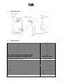
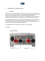
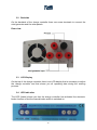
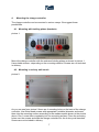
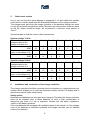
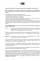
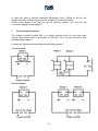
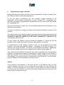
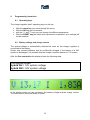
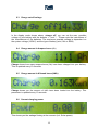
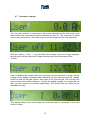
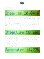
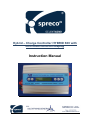
Hybrid – Charge Controller HYBRID 600 with LCD-multi-function-display Instruction Manual Congratulations, you have bought a high-quality SPRECO hybrid charge regulator HYBRID 600 Before first using this gadget please carefully read this manual . General information: The Silentwind-Charge-Regulator HYBRID 600 is a combined wind and solar charge regulator with an inbuilt micro-controller. The Silentwind-charge-controller HYBRID 600 was especially developed for the Silentwind Generator and enables you additionally to install solar panels up to a wattage of 180 Watt peak or to a max. current of 10A. Consumers with a maximum current of 10 Amps that are connected to the deepcycle output can be automatically switched off or on by a deep cycle protection function. All operating parameters can be seen on an LCD-display. You can adjust the charge regulator with 5 touch keys on the right and left of the LCD-display. A LED´s on top of the controller additionally informs you about the operating status “brake active”. A LED on top of the case, below the LCD-display, additionally informs about the either manually or automatically activated brake function. A thermically switched vent provides the correct operating temperature. The Silentwind Generator generates 3phase AC-voltage. In the charge controller AC is transformed to DC. 12 or 24 voltage is automatically detected after the first installation. All types of lead batteries (Gel, AGM and acid) can be charged. The suitable maximum charge voltage - depending on the type of battery - must be adjusted in the Setup. The charge-controller is Advice: Please keep in mind that liquid acid batteries can emit dangerous explosive gas. If the place where you mount the charge controller is close to these batteries, ensure efficient ventilation. Gel or AGM batteries are normally maintenance free and do not emit gas if properly charged. Always make sure charge controller is mounted in a dry and as cool as possible place. 2 Inhaltsverzeichnis: 1. wiring diagramm 4 2. technical data 4 3. components of the charge controller 6 3.1 frontside 6 3.2 backside 7 3.3 LCD – display 7 3.4 LED – indicator 7 4. mounting the charge controller 5 4.1 mounting by holding brackets 5 4.2 mouting in a slurry wall trench 5 5. Cable – cross section 8 6. installation and Connection of the charge controller 8 7. connecting solar panels 10 8. programming charge controller 11 9. programming instruction 12 9.1. operating keys 12 9.2. battery voltage and charge current 12 9.3. charge cut-off voltage 13 9.4. charge amount in ampere hours (Ah) 13 9.5. charge amount in kilowatt hours (kWh) 13 9.6. current charging power 14 9.7 consumer settings 14 9.8 brake adjustments 15 9.9 generator voltage 16 10. troubleshooting 17 3 1. wiring diagramm 2. Technical data hybrid-charge controller type Battery system voltage (automatically detected) Max. power input of the wind generator Max. current input of the wind generator Max. power input of the solarpanel Max. current input of the solarpanel Max. open circuit voltage input of the solarpanel Max. total charge current Max. switch off current at LOAD-output (Load) Max.voltage adjustable for the battery types Dimensions (LxWxH) in mm Weight Suitable for Warranty HYBRID 600 12 or 24 Volt 600 W 30A 180Wp 10A 50VDC 40 A 10 A acid, gel or AGM 190 x 120 x 65 1,15 kg acid, gel and AGM 24 months Features Thermically switched vent Cable connection Integrated electronic brake Integrated manual brake switch LCD-display of all relevant working data LED shows the operating status LED for brake function 4 automatically screw terminals Ø 7mm charge limitation storm brake W, A, V/Ah, kWh brake active LED occurs = brake activated 3. Components of the charge controller 3.1 Frontside On the front of the charge controller there are screw terminals to connect the battery. There are also screw terminals for the automatically switched load output (user output) as well as the brake switch to activate manually the brake function. Please note that the brake switch in position “I” means that the brake is activated / switched on manually, but it does not mean that the wind generator is switched on. The brake switch does not totally stop the blade rotation. The blades will still turn slowly. If the brake is manually or electronically activated, the LED “brake” will lit up. The brake switch should be manually activated in case of storm, maintenance or if you want to work close by the Silentwind Generator. For automatic brake mode please switch position “0” (“RELEASE”) Front view: 5 3.2 Backside On the backside of the charge controller there are screw terminals to connect the wind generator and the solar panels. Rear view: 3.3 LCD-Display On the top of the charge controller there is an LCD-display that is necessary to adjust the charge controller and that shows you all operating data during the working process. 3.4 LED-indication The LED (brake) shows you that the charge controller has activated the electronic brake function or that the manual brake switch is switched on. 6 4. Mounting the charge controller The charge controller can be mounted in various cways. We suggest these possibilities: 4.1 Mounting with holding plates (brackets) picture 1: Mount the charge controller with the enclosed holding plates as shown in picture 1. Use suitable screws - depending on the mounting material. Screws are not included in delivery. 4.2 Mounting in a slurry wall trench picture 2: As you can see from picture 2 there are 4 mounting holes on the back of the charge controller. Use filister head screws with appropriate (suitable) diameter and screw them into the mounting surface according to the measurements shown in the picture above. Don´t screw them completely into the mounting surface. Place the mounting holes over the screws and slide the charge controller into the 4 slurry wall trenches. Screws are not included in delivery. 7 5. Cable cross section As you can see from the wiring diagram in paragraph 1 a 3-pole cable with suitable cross section must be wired from the Silentwind-Generator to the charge controller. The charge power gets from the charge controller to the batteries through two wires (on the AC entrance through three wires) Therefore the cross section of the two wires on the DC output should be larger, we recommend a minimum cross section of 10mm2. See below table to find the correct cable cross section: System voltage 12 Volt Distance from windgenerator to the charge controller in m Cable cross section mm2 AWG Distance from the charge contr. to the battery in m Cable cross section mm2 AWG System voltage 24 Volt Distance from windgenerator to the charge controller in m Cable cross section mm2 AWG Distance from the charge contr. to the battery in m Cable cross section mm2 AWG 6. 0-9 10 – 19 20 – 29 30 – 44 45 – 69 70 – 110 6 10 0-9 10 8 10 – 19 16 6 20 – 29 25 4 30 – 44 35 2 45 – 69 50 1 70 – 110 10 8 16 6 25 4 35 2 ----- ----- 0-9 10 – 19 20 – 29 30 – 44 45 – 69 70 – 110 2.5 14 0-9 4 12 10 – 19 6 10 20 – 29 10 8 30 – 44 16 6 45 – 69 25 4 70 – 110 10 8 16 6 25 4 35 2 ----- ----- Installation and connection of the charge controller: The charge controller should be mounted close to the battery in a ventilated and cool location which enables you to read the information shown on the LCD display and to operate the manual brake switch easily. Safety advice: Especially acid batteries can emit gas when charging. Therefore the charge controller must not be installed close to those batteries. In case of high concentration of dangerous gas there is a risk of explosion. Please note the safety regulations, -advice of the battery producer. If the acid batteries are equipped with ventilation pipes to the exterior or if the storage room of the batteries is otherwise ventilated, the charge controller can be installed close to the batteries. 8 Please find a sketch of the wiring diagram in the paragraph 1 of this manual. Make sure that you fix the wires properly to prevent them from getting loose due to vibrations. Fix the plastic screw nuts sufficiently to ensure electric contact. We recommend the use of the enclosed wire kits 3 x H07V-K 4mm2, red (input of 3 phases of the wind generator) 1 x H07V-K 6mm2, red (output "+" to battery) 1 x H07V-K 6mm2, black (output "-" to battery) Connect the free end of the connecting wire with your wires coming from the wind generator and the battery with suitable insulating screw joints. In case you do not use the connecting wires we recommend the use of crimp type cable sockets to fix your wires directly to the charge controller. After having fixed the crimp type cable sockets with the bared wires these can be fixed to the cable sockets. It is most important that you first connect the charge controller to the battery with the right polarity. Attention: On the output of the charge controller there must not be an additional brake switch ! In case there is such a brake switch due to the previous installation of a wind generator this must be removed. Please connect the enclosed fuse (50Amp.) close to the battery in the positive wire. The fuse is only included in delivery if you buy a wind generator (not only a charge controller). Attention: The confusion of Plus and Minus will definitely destroy your charge controller. In that case warranty is gone. After the connection of the battery you can connect the load output, the Silentwind Generator and -if required- a solarpanel. On the 3-phase output wires of the Silentwind you need not to pay attention to polarity. If you want to connect 24 volt batteries to the charge controller, make sure that the voltage of the batteries is above 20 Volt. Otherwise the charge controller will detect a 12 volt battery system. If you install this system after having used another windgenerator with a stop switch, make sure that this switch is deactivated or removed. If there is sufficient windspeed when connecting the Silentwind Generator, this will immediately generate electric power at the end of the 3 AC-wires without being connected to the charger. Therefore we recommend to block the Silentwind Generator blades with a rope before connecting the wires to the charger. The 3 AC output wires must be connected to the 3 screw terminals on the back of the charge regulator. (see paragraph 3.2). In a 3 phase AC system the connection order / polarity does not matter. 9 In case you want to connect additional solarpower (max. 180Wp or 10A) to the charge controller, this should be done by using the PV screw terminals. Please make always sure that you do not confuse polarity. You can find the connection diagram in paragraph 7. 7. Connecting solar panels The charge controller Hybrid 600 is a hybrid controller both for wind and solar energy. Solar panels with a max power of 180 Wp / 10 A can be connected, See technical details page 4. Connect the solar panels according to the following sketch. 12 volt system: 24 volt system: 10 8. Programming charge controller Before first using the charge controller it must be adjusted to the type of battery (acid, gel, AGM) you want to use (see paragraph 9). At first you have to programme the max. possible voltage according to the instructions of the battery manufacturer in step “Charge Off” ( paragraph 9.3). Secondly you have to programme the requested switch off current at the step “Break On” (paragraph 9.8). We also recommend to make use of the additional adjustments according to your individual requirements. If the point of maximum voltage is reached, the Silentwind Generator will stop for 20 minutes. The break mode of the charge regulator generates internal rising temperatures that are thermically detected. Therefore the break time of the Silentwind Generator will be increased in high wind speeds until the internal temperature is reduced by the automatically switched vent. For this reason the charge controller should be installed on a place as cool as possible. Never install the controller at direct solar radiation or sunlight. A special feature of this charge controller is that you can programme the break function. If the maximum possible voltage – according to the type of battery – is reached, the charge controller will switch of the Silentwind Generator. Additionally the maximum charge current can be adjusted (see chapter settings page 12) This means that the Silentwind Generator can also be operated with a larger battery capacity. If a large battery capacity is discharged, a higher charge current will flow in high wind speeds. As you can set the maximum charge current you can prevent overheating of the charge controller. As described in step “Break On” you can reduce the max. charge current according to the requirements. Advice: If the capacity of the batteries is less than 150 Ah, or old batteries have lost their original capacity, the point of max. voltage can be reached very fast although the battery is not fully charged yet. In this case it can be useful to connect an electric consumer to the Load-output, as this will reduce the voltage and thus prevent that the break mode is activated too early. 11 9. Programming instruction 9.1 Operating keys The charge regulator has 5 operating keys on the top: With the menu key you move through the menu. With the OK key you move back. with the "+" and "-" keys you can change the different parameters With the RESET key the inbuilt micro-processor is restarted, your settings will not be resetted. 9.2 Battery voltage and charge current The system-voltage is automatically detected as soon as the charge regulator is connected to the battery. Please only connect batteries that are sufficiently charged. If the battery of a 24V system is discharged, it is possible that the charge controller detects a 12 V system. After the first connection the display shows the following data: The display shows: Hybrid NL = 12V system voltage Hybrid NH = 24V system voltage In the display mode you can see above the battery voltage and the charge current. The total current (wind and solar) is shown. 12 9.3 Charge cut-off voltage In the display mode shown above „charge off“ you can set the max. possible voltage of your battery with the buttons “+” and “-“ . Please note the instructions of the manufacturer of the batteries. The maximum possible voltage is dependent on the system voltage (12/24V) and the type of battery (acid, Gel or AGM) 9.4 Charge amount in Ampere hours (Ah) Charge shows how many ampere-hours (Ah) have been charged into your battery. This is updated every 10 seconds. 9.5 Charge amount in Kilowatt hours (kWh) Charge shows you the amount of kWh have been loaded into the battery. This parameter is updated every 10 seconds. 9.6 Current charging power This shows you the wattage flowing at the moment (incl. Solar-power). 13 9.7 Consumer settings You can also connect a consumer to the screw terminals of the load output and define when the consumer should be switched on and off. The consumer is called user in the picture above. This shows you how many amphours the user has taken. With the button „+“ and „-„ you can define the voltage when the charge regulator should switch off the consumer. Please note that this must not be higher than 10 Amp. User on defines the voltage when the consumer can be switched on again. As the voltage of the battery increases when switching off the consumer this will steadily switch on and off the load output if this value is not high enough. This function can also be used with smaller batteries.. So that the charge voltage is not detected too fast, you can connect a consumer additionally. This avoids that the brake will be activated too early. This setting shows how much amps the consumer that is connected to the load output is using. 14 9.8 Brake adjustment With +/- you can set the current when you want to stop the Silentwind Generator. This prevents overheating, especially with big battery banks and high loading currents. This function can also be used to reduce the RPM of the Silentwind Generator. You can calculate the max. charge current value as follows: The max. power of the Silentwind Generator 400 Watts divided by the max. cut-off voltage e.g. 14,4 Volt at a AGM battery. The max. possible charge current in this example is 400VA / 14,4V = 27,7Amp. Breaktime: With this setting you can programme the period of time that you want to stop the Silentwind. The longer you programme the time, the longer the first break intervals will take. This procedure will heat up the inbuilt brake resistores resulting in a permanent brake mode until the vent has cooled down. Therefore this time should not be programmed below 50sec. 9.9 Generator voltage: ! Reference voltage - only relevant for service purposes ! 15 If the charge controller is correctly connected, the manual break switch on the front of the charge controller can be switched in position “0”. The Silentwind Generator will then start to turn faster until the charging process starts. The charge controller now starts operating and monitors all special settings that you have programmed according to the type of battery and the instructions of the battery manufacturer (see examples for settings). Saftey advice: Please never disconnect the battery wires while the Silentwind Generator is charging. This will immediately destroy the charge controller. If you want to measure the current flowing, an amp-meter must be installed in the positive battery wire. Mind the polarity of the amp-meter. The flowing current can be seen at the LCD-display. Notices 16 10. Troubleshooting The blades of your Silentwind Generator are turning too slowly The manual stop switch of the charge controller is in position „I“ (“BRAKE”). Connecting the wires possibly caused a short circuit between the wires. The wind speed is too low. The fuse connected to the battery is gone. Your Silentwind Generator or the charge regulator has an internal problem. Please contact your dealer. In order to find the mistake you have to check the installation chain starting at the 3 wires of the Silentwind Generator connected to the charge controller. In case the Silentwind Generator does now start (without connection to the charge controller) the failure is between charge regulator and battery. BE CAREFULL, don´t touch the end of the cables because of the electric power that occurs at these ends. If the Silentwind Generator continues to turn slowly, the failure is between charge controller and Silentwind Generator. Mind the recommended cross section of the wire as well as the recommended minimum capacity of the battery that you want to charge. If the Silentwind Generator generates too little power The wind speed is too low, see the performance diagrams shown in the manual of the Silentwind. The wind speed measured on top of the mast is higher than at the position of the wind generator! Turbulences by obstacles in the wind direction or the location is unsuitable, mast to short. The wire cross section is not in line with the lenght of the wires installed. (see page 3). The battery-capacity is below 100Ah so that the maximum possible voltage is generated too fast. The battery is too old and has lost capacity so that the maximum power voltage is achieved too fast. Enjoy collecting regenerative power. You contribute protecting the environment and saving your money ! Your Spreco Team edition: October 2011 17 18