1
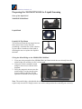
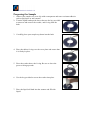
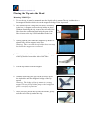
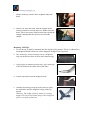
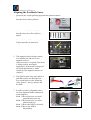
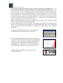
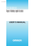
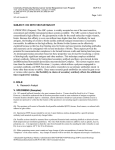
NSOM/SPM-100 Liquid Cell
USER MANUAL
March
(Version C)
RESTRICTION ON THE USE, DUPLICATION, OR DISCLOSURE OF PROPRIETARY INFORMATION. This document
contains proprietary information which is the sole property of Nanonics Imaging Ltd. This document is submitted to the recipient for his or
her use only.
Preparing the NSOM/SPM-100 for Liquid Scanning
Parts of the Liquid Cell
NSOM/SPM-100 Head
Liquid Bath
Liquid Cell Tip Mount
You will notice that the tip mount has two
holes; these holes can be used for
permitting a constant flow of the solution
of your choice in and out of the bath or
allowing the user to replace the liquid in
the bath.
Fixing the Metal Bridge to the NSOM/SPM-100 Head
1. If you are using a model of the NSOM/SPM-100 Head which does not already have the
metal bridge you will have to fix it to the head.
2. Using two screws attach the metal
bridge to the head, as shown in the
diagram.
3. Place the magnetic mirrors onto the
metal bridge, leaving enough space
between them so that the circular
aperture of the bath is left exposed.
Note: The metal bridge, which holds the mirror, can also be used for other applications that
require only one mirror. Simply remove one mirror and position the remaining one correctly.
Preparing the Sample
1. Adhere your sample to a cover slip with a transparent and water resistant adhesive
such as polylysine or nail enamel.
2. Turn the liquid bath upside down, then use the key provided
to unscrew and remove the washer, and O-ring from the
bath.
3. Carefully place your sample top down into the bath.
4. Place the rubber O-ring over the cover plate and ensure that
it is firmly in place.
5. Place the washer above the O-ring. Be sure to leave the
grooves facing upwards.
6. Use the key provided to screw the washer into place.
7. Place the liquid cell bath into the scanner and fill with
liquid.
Placing the Tip onto the Head
Mounting NSOM Tips
1. To use the tip, it must be mounted onto the liquid cell tip mount.The tip is adhered to a
feromagnetic holder which sits on the magnetic bridge of the tip mount.
2. The NSOM tip has a long fiber tail that is wound up
in the box. A magnet secures the tip holder in place.
Without disturbing the tip, remove the tail end of the
fiber from the cushioning until only the part of the
fiber closest to the tip is still imbedded in the box.
3. Gently push the fiber until the magnetic tip holder is
almost fully off the magnet in the box.
Warning: Take care that the tip holder does not snap
back onto the magnet once removed.
4. Using a pair of cantilevered tweezers, get a firm grip
of the tip holder from either side of the fiber.
5. Lift the tip holder from the magnet.
6. Without loosening your grip on the tweezers place
the tip holder onto the magnetic bridge of the tip
mount.
Warning: The bridge of the tip mount is a strong
magnet. Do not let tip holder jump to the bridge but
place it carefully in position.
7. Once you have placed the tip onto the mount, gently
tuck the tail of the tip under the clip.
Fiber
tail
Tip
holder
8. Open the NSOM/SPM-100TM head and place the tip
mount (with tip) onto the three magnets under the
head.
9. Before you close the head, turn the stepper motor
counter clockwise to bring the lever further from the
head. This leaves more room between the tip and the
sample ensuring that the tip does not touch the
sample.
Mounting AFM Tips
1. To use the tip, it must be mounted onto the liquid cell tip mount. The tip is adhered to a
feromagnetic holder which sits on the magnetic bridge of the tip mount.
2. The AFM tip is secured into its box by a magnetic
strip (in most boxes there will be more than one tip).
3. Using a pair of cantilevered tweezers, get a firm grip
of the tip holder from either side of the fiber.
4. Lift the tip holder from the magnetic strip.
5. Without loosening your grip on the tweezers place
the tip holder onto the magnetic bridge of the tip
mount.
Warning: The bridge of the tip mount is a strong
magnet. Do not let tip holder jump to the bridge but
place it carefully in position.
6. Once you have placed the tip onto the mount, gently
tuck the tail of the tip under the clip.
7. Open the NSOM/SPM-100TM head and place the tip
mount (with tip) onto the three magnets under the
head.
8. Before you close the head, turn the stepper motor
counter clockwise to bring the lever further from the
head. This leaves more room between the tip and the
sample ensuring that the tip does not touch the
sample.
Removing a Tip from the Tip Mount
Once the tip holder completes the magnetic bridge of the tip mount a strong magnet is
formed. It is quite easy therefore, when removing the tip, to let the tip holder snap back. This
could break the tip. To avoid this, make sure that you have a firm grip on the tip holder
before you attempt to lift it from the magnetic bridge.
Aligning the Feedback Laser
1. Switch on the Topaz controller and Start the Quartz software.
2. Turn the knob on the Topaz NSOM
Interface box to Inner position.
3. On the rear of the Topaz NSOM
Interface box, move the switch to
liquid.
4. Set the Reference Force value on the
Topaz controller at about zero.
5. The magnetic mirror bridge consists
of a metallic bar and one or two
magnetic mirrors.
Only one mirror is required if the head
is being used for non-liquid
applications. If the head is being used
for liquid applications or with a
silicon tip, two magnetic mirrors are
required.
Mirror 2
Mirror 1
6. The light from the laser must follow a
path that results in reflection from
four crucial places in the following
order: mirror 1, the tip, mirror2 and
the PSD.
7. In order to achieve alignment, there
are four alignment knobs (numbered
in the diagram).
Knob 1: Moves the laser on a track
perpendicular to the tip.
Knob 2: Moves the laser on a track
parallel to the tip.
Knob 3: Moves the PSD in vertically.
Knob 4: Moves the PSD in
horizontally.
3
4
2
1
8. Set the laser beam approximately in the center of the mirror by turning knob 1 (for
movement perpendicular to the tip) and knob 2 (for movement parallel to the tip).
9. The position of the mirror can be moved until the reflected laser ray makes contact with
the tip. This can be done by sliding the mirror along the bridge until reflection is evident.
10. If a second mirror is being used, the light has to reflect from mirror 2. To check if the
laser has hit mirror 2, insert a small piece of paper above the bridge. If there is no sign of
the laser ray on the paper, then it has hit mirror 2. If you see an arch reflected on the
paper, then the angle and/or placement of mirror 2 is incorrect. Change the angle of
mirror 2 with a tweezers as in the previous step.
11. Note: when adjusting the mirrors, try to position them so that you leave exposed as much
of the circular aperture below them as possible.
12. The ray should hit the center of the PSD. The position of the PSD can be changed using
knob 3 (for vertical movement) and knob 4 (for horizontal movement). Try to attain the
correct position without using knob 4 as altering this knob could cause alignment
difficulties.
13. Click on the Target icon, which will bring the PSD
Alignment Window onto the monitor. This represents
the placement of the reflected laser on the PSD.
14. The reflected ray should be positioned so that it hits the
center of the PSD. This can be achieved by turning knob
number 3 on the head, which will move the PSD up and
down. There is no need for lateral adjustment of the
PSD. When the + on the screen is on the horizontal line,
the PSD and the reflected ray are correctly positioned.
15. If the sum signal is higher than 10V, it can be reduced
using the SM Reset knob on the rear of the Topaz
NSOM interface box.