1
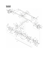
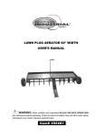
LAWN PLUG AERATOR 50" WIDTH
USER’S MANUAL
Read carefully and understand RULES FOR SAFE OPERATION and instructions before
operating. Failure to follow the safety rules and other basic safety precautions may result
in serious personal injury.
Item# 250280
For technical questions and replacement parts, please call 1-800-222-5381.
Thank you very much for choosing a NORTHERN TOOL + EQUIPMENT CO., INC.,
Product! For future reference, please complete the owner’s record below:
Model: _______________
Purchase Date: _______________
Save the receipt, warranty and these instructions. It is important that you read the entire
manual to become familiar with this product before you begin using it.
This machine is designed for certain applications only. Northern Tool + Equipment
strongly recommends this machine is not modified and/or used for any application other
than that for which it was designed. If you have any questions relative to a particular
application, DO NOT use the machine until you have first contacted Northern Tool +
Equipment to determine if it can or should be performed on the product.
TO
THE
CUSTOMER
This manual contains valuable information about your new aerator. It has been
carefully prepared to give you helpful suggestions for operating, adjusting, and
servicing.
Keep this manual in a convenient place for quick and easy reference. Study it
carefully, only by proper care and operation can you expect to receive the service
and long life designed and built into this aerator.
GENERAL
SAFETY
RULE
EQUIPMENT SAFETY GUIDELINES
Safety of the operator is one of the main concerns in designing and developing a new
piece of equipment. Designers and manufacturers build in as many safety features as
possible. However, every year many accidents occur which could have been avoided by a
few seconds of thought and a more careful approach to handling equipment. You, the
operator, can avoid many accidents by observing the following precautions in this section.
To avoid personal injury, study the following precautions and insist those working with you,
or for you, follow them.
In order to provide a better view, certain photographs or illustrations in this manual may
show an assembly with a safety shield removed. However, equipment should never be
operated in this condition. Keep all shields in place. If shield removal becomes necessary
for repairs, replace the shield prior to use.
Never use alcoholic beverages or drugs which can hinder alertness or coordination while
operating this equipment. Consult your doctor about operating this machine while taking
prescription medications.
Review the safety instructions with all users annually. This equipment is dangerous to
children and persons unfamiliar with its operation. The operator should be a responsible
adult familiar with farm machinery and trained in this equipment's operations. Do not
allow persons to operate or assemble this unit until they have read this manual and
have developed a thorough understanding of the safety precautions and of how it
works.
To prevent injury or death, use a tractor equipped with a Roll-Over Protective System
(ROPS).
Never exceed the limits of a piece of machinery. If its ability to do a job, or to do so safely,
is in question -DON'T TRY IT.
Do not modify the equipment in any way. Unauthorized modification may impair the
function and/or safety and could affect the life of the equipment.
In addition to the design and configuration of this implement, including Safety Signs and
Safety Equipment, hazard control and accident prevention are dependent upon the
awareness, concern, prudence, and proper training of personnel involved in the operation,
transport, maintenance, and storage of the machine. Refer also to Safety Messages and
Operation Instructions in each of the appropriate sections of the Tractor and Aerator
Manuals. Pay close attention to the Safety Signs affixed to the Tractor and the Aerator.
RULES FOR SAFE OPERATIONS
Remember, any power equipment can cause injury if operated improperly or the user
does not understand how to operate the equipment.
LOOK FOR THIS SYMBOL
TO POINT OUT IMPORTANT SAFETY
PRECAUTIONS. IT MEANS ATTENTION! BECOME ALERT! YOUR SAFETY IS
INVOLVED.
CAUTION: VEHICLE BRAKING AND STABILITY MAY BE AFFECTED WITH THE
ADDITION OF AN ACCESSORY OR AN ATTACHMENT. BE AWARE OF CHANGING
CONDITIONS ON SLOPES.
Exercise caution at all times when using power equipment.
1. Read this owner’s manual carefully for operating and service instructions before
attempting to assemble or operate this equipment. Be thoroughly familiar with the proper
use of this equipment.
2. Read the vehicle owners manual and vehicle safety rules, and know how to operate the
vehicle before using this equipment.
3. Never allow children to operate the tractor or aerator attachment, and do not allow
adult’s to operate without proper instructions.
4. This aerator attachment has sharp points. Always handle with care and wear
substantial foot wear when operating this aerator.
5. Do not allow anyone to ride or sit on aerator attachment frame or on towing vehicle.
6. Keep the area of operation clear of all persons, particularly small children, and also
pets.
7. Always begin with the transmission in first (low) gear and engine at low speed, and
gradually Increase speed as conditions permit.
8. Vehicle braking and stability may be affected with the attachment of this equipment. Be
aware of changing conditions on slopes. Refer to safety rules in the vehicle owner’s
manual concerning sale operation on slopes.
9. Always operate up and down a slope, never across the face of a slope.
10 This equipment should be operated at reduced speed on rough terrain, along creeks
and ditches and on hill sides, to prevent tipping and loss of control. Do not drive too close
to a creek or a ditch.
11. Do not tow this equipment on a highway or any other public thorough fare.
12. Follow the maintenance instructions as outlined in this owner’s manual.
ASSEMBLY
STEP1: Assemble 8 aerator knives to a double spool assembly using sixteen M8 x 20
carriage bolts, 8 lock washers and M8 hex lock nuts. All knives should face the same
direction. Tighten. Repeat for other double spool assemblies.
STEP2: Push a split plastic bearing into each end of the spool tube.
STEP3: Assemble a wheel bracket to the middle hole in the shaft so that the hub faces
the short end of the shaft. Fasten the bracket to the shaft using a 1/4" x 1-8/16" hex bolt
and a 1/4" hex lock nut. Tighten.
STEP4: Pre-assemble a M8 x 30 hex bolt and M8 hex lock nut to the smaller hole in the
wheel bracket. Insert the bolt from the hub side of the bracket. Do not tighten yet.
STEP5: Assemble double spool assembly (knives facing in), a 5.29" long spacer, another
double spool assembly (knives facing out), a 1.00" long spacer and a 20 flat washer onto
the short end of the shaft.
STEP6: Assemble a 2.38" long spacer, a 20 flat washer, the middle bracer, a 20 flat
washer, a 2.9" long spacer, a double spool assembly (knives facing in), a 5.29" long
spacer, a double spool assembly (knives facing out), a 1.00" long spacer and a 20 flat
washer onto the long end of the shaft. The bent lip of the middle brace must face the short
end of the shaft.
STEP7: Rotate the wheel bracket fastened to the middle of the shaft so that it is pointing
up. Assemble an end plate, a 20 flat washer and a wheel bracket onto the long end of the
shaft. Point the wheel bracket. Fasten to the shaft using a 1/4" x 1-9/16” hex bolt and 1/4"
hex lock nut. Tighten. Repeat for other end of shaft.
STEP8: Assemble a wheel to the left and right wheel brackets. Use a M12 x 110 hex bolt
and 12 big flat washer and M12 nuts. Adjust the nuts so that the wheel is held securely.
Repeat on right side but will spin freely.
STEP9: Assemble the hitch bracket to the tongue using two M8 x 25 hex bolts and M8
hex lock nuts. Tighten.
STEP10: Assemble the hitch pin through the hitch bracket and the tongue. Secure it with
the hair cotter pin.
STEP11: Assemble the tongue to the tray, placing the wide end of the tray slot to the front
with two M8 x 25 hex bolts, two M8 x 30 hex bolts, four 1/4" long spacers, four M8 hex
nuts. Tighten.
STEP12: Assemble two M8 x 30 hex bolts, four 1/4" long spacers, two M8 hex lock nuts
to the holes on the right side of the slot in the tray. Tighten.
STEP13: Align the tray between the end plates. Use three M8 x 20 hex bolts to
temporarily secure three corners of the tray to the end plates. Leave one upper corner
empty.
STEP14: Rotate the middle brace up against the tongue, aligning it with the holes that are
closest to slot in the tray. Fasten the brace to the tongue using two M8 x 25 hex bolts, M8
hex lock nuts. Do not tighten till final step.
STEP15: Assemble both of the end plates to the tray using eight M8 x 20 hex bolts, M8
hex lock nuts. Do not tighten till final step.
STEP16: Place the lift handle through the slot in the tray. Fasten the lift handle to the
smaller hole in the middle wheel bracket using the bolt and hex lock nut which you
pre-assembled earlier. Fasten the lift handle to the larger hole in the wheel bracket using
a M8 x 30 hex bolt, the shoulder spacer, a M8 hex lock nut. Tighten.
STEP17: Push the grip onto the lift handle.
STEP18: Place the aerator right side up its wheels, locking the lift handle into the offset at
the front of the tray slot. Perform the following steps to assure correct alignment of the lift
handle with the slot.
1. Adjust the tray side to side until the lift handle rests against the right side (viewed from
rear) of the offset at the front of the slot.
2. Straighten the end plates and then tighten the eight bolts at the corners of the tray,
making sure the lift handle still rests against the right side of the slot offset.
3. Straighten the middle brace and tighten the two bolts which fasten it to the tongue.
STEP19: Make sure the lift handle still rests against the right side of the slot offset. You
should have to force the handle over into alignment with the slot when lowering the
aerator.
OPERATION
Aerating involves cutting small holes in the soil to create small reservoirs that bring
oxygen, fertilizer and water down into the root zone. For best performance of the spike
aerator attachment, the following lawn preparation and aerator operation is
recommended.
Spike points are sharp. Exercise caution at all times when spike points are rotating or
when points are being handled.
1. To level the spike tray after the aerator is attached to the tractor hitch, loosen the lock
washers and hex nuts holding the hitch mount arms to the brackets at the rear of the tray,
make the tray as level as possible and then retighten the nuts.
2. The spike tray may be raised to the transport position by pushing the lift handle
backward.
3. The spike tray may be lowered to the working position by moving the lift handle
forward.
4. Mow the lawn and remove loose clippings prior to use of the aerator.
5. Start the tractor engine with controls in neutral and then place throttle at a slow engine
speed.
6. Engage the shift lever in lowest possible forward speed and then lower the aerator,
allowing spike points to enter the ground. Increase speed as conditions permit.
7. Aerate in the straightest line possible.
8. Make overlapping passes to Increase density to the spike point pattern.
9. To prevent damage to lawn, do not make sharp turns while spike points are engaged in
ground.
10. Aerate in an up and down direction on slopes
11. To Increase depth of spike point penetration, add weight to the tray as necessary. The
tray holds concrete blocks or patio blocks at approximately 35 lbs. each. Secure the
weight with straps or wire using the tray flange.
12. If the ground is extremely hard and dry, it should be sprinkled or watered down for one
to two hours prior to the aerator.
13. Do not aerate if the ground is too wet or muddy.
MAINTENANCE
1. Before each use check all nuts and bolts for tightness.
2. Lubricate wheels as needed. (Normal lubricant is applicable.)
3. If rust appears on shield or spikes, sand Iightly and coat with enamel paint.
4. Store in a dry area and coat exposed metal with right oil when not in use. (Normal
grease oil is applicable.)
5. Spike points can be periodically sharpened with a small grinder to maintain good soil
penetration. Points should be removed for sharpening.
STORAGE
&
SAFETY
1. Store the unit in an area away from human activity. Do not permit children to play on or
around the stored unit.
2. Make sure all parked machines are on a hard, level surface and engage all safety
devices.
3. If blocking is used, make sure it is solid and secure before leaving area.
DIAGRAM
PARTS
LIST
No.
Description
Qty.
No.
Description
Qty.
1
2
3
4
5
6
7
8
9
10
11
12
13
14
15
16
17
18
Tray
Middle Brace
Side Support
Lift Handle
Moving Bridge
Shaft
Hitch Bracket
Wheel
Wheel Carrier
Turntable Assembly
Lock Pin
Bolt M8x30
Bolt M8x25
Spacer 1/4"L.
Knife Tool
Carriage Bolt M8x20
Lock Nut 8
Shaft Shoulder
1
1
2
1
1
1
1
2
3
4
1
6
6
8
32
64
84
1
19
20
21
22
23
24
25
26
27
28
29
30
31
32
33
34
35
Bolt M8x20
Flat Washer 8
Bolt 1/4"x1-9/16"
Hitch Pin
"R" Pin
Bolt M12x110
Lock Nut M12
Big Flat Washer 12
Nut M12
Plastic Bush
Spacer 2-1/3"L.
Spacer 1"L.
Spacer 3"L.
Spacer 5-1/3"L.
Taper Knob
Flat Washer 20
Lock Nut 1/4"
8
8
3
1
1
2
2
2
2
8
1
2
1
2
1
6
3
Northern Tool + Equipment Co.,
2800 Southcross Drive West
P.O. Box 1499 Burnsville, MN 5337-0499
Made in China