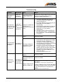
1
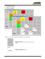
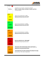
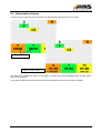
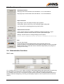
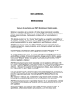
Call System
User’s Manual
User’s Manual
13 September 2011
HNS ANDON
Call System
Copyright © 2011
HNS Technical Development Ltd.
H-9027 Győr, Gesztenyefa 4.
www.hns.eu/spce
Phone.: +36 (96) 506-930
Fax: +36 (96) 506-931
E-mail: [email protected]
Content
1
2
3
4
5
Functionality........................................................................................................................................... 3
Requirements ......................................................................................................................................... 4
Program installation .............................................................................................................................. 4
Program start ......................................................................................................................................... 4
Program usage....................................................................................................................................... 5
5.1
Status display ........................................................................................................................................................ 5
5.2
Visualisation display............................................................................................................................................... 7
5.3
Function panel ....................................................................................................................................................... 8
5.4
Administrative functions ......................................................................................................................................... 8
5.4.1 Users ................................................................................................................................................................... 8
5.4.2 Settings................................................................................................................................................................ 9
5.5
Report functions................................................................................................................................................... 10
5.5.1 Daily report ........................................................................................................................................................ 10
5.5.2 Calling data........................................................................................................................................................ 11
5.5.3 Log .................................................................................................................................................................... 12
5.6
Exit....................................................................................................................................................................... 12
Appendix
Andon Call Station (Call Device)
USB-CAN Interface (USB/CAN Gateway)
CAN Bus Cabling Information
Troubleshooting
HNS ANDON
User’s Manual
2
1 Functionality
The production staff – in case of incapacitation - can ask for help to his job with usage of Lean ANDON
based call system from different fields.
The program serves up to 30 ANDON call devices. The worker can ask for help with pushing the appropriate
button of the call unit. The handling program accepts and reports back the request. The program handles the
call acknowledgements. The program writes the ANDON events of line into log and call files. Daily report can
be made about calls and services.
The following illustration shows the contact between the system and the HNS ANDON devices.
The visualisation software is part of the production site
manufacturing-information system. In normal case
these system information are visible on the displaying
tool. The second display of HNS ANDON system will
be activated in case of ANDON call.
©
PC
MS Windows
Extended
Desktop
Visualisation Software
(External Application)
HNS ANDON
Program
Sound Card
COM
Ethernet
Helyi
kezelő
felület
Beállítások
Naplózás
Reports
USB
USB-CAN Interface
(USB/CAN Gateway)
Intranet LAN
USB-CAN
Interface
External
Power Supply
(optionally)
30.
HNS ANDON
Power Supply
CAN Bus
. . .
29.
...
User’s Manual
3.
2.
1.
3
2 Requirements
•
HNS ANDON Program
This program runs on Microsoft Windows operation system.
See third section about installation of the HNS ANDON program!
•
USB-CAN Interface (USB/CAN Gateway)
Driver of USB-CAN Interface must be installed on the PC (new virtual COM port has to be appeared)
and USB-CAN interface has to be connected to an USB port of the PC.
See Appendix!
•
Visualisation Display
TV screen installed and configured to display extended desktop.
•
Sound System
Amplifier and speaker(s).
•
CAN Bus
Cable system, see Appendix!
•
ANDON Call Stations
Call Stations must be connected to the USB-CAN Interface via CAN bus.
See Appendix!
3 Program installation
The program has to be installed with HNS ANDON Setup.exe program located on the HNS ANDON CD, but
the HNS ANDON software can be also downloaded from www.hns.eu/spc. The install program installs the
files necessary to run the program into the C:\Program.Files\HNS.ANDON folder of your computer.
Suggestion
The program is practically started automatically on user’s logging in therefore a shortcut has to be created
manually at the Start-up group of the Windows (the name of the program file is C:\Program
Files\HNS.ANDON\HNSANDON.exe; the starting status is practically set as minimized).
4 Program start
The program can be started clicking on the Call System item of the HNS.ANDON menu.
Attention!
If the program is configured to start automatically when user is logged in as above mentioned then do not
start it manually again!
Attention!
Before you turn off the computer you have to close the HNS ANDON – Call System program, stop the call
system and close the program clicking on the right-up
icon of the program’s main form or push the F10
function key.
HNS ANDON
User’s Manual
4
5 Program usage
5.1 Status display
Subtitles and colours show status of the Call Stations as you can see below.
Station is out of use.
(Using of the Call Station has been turned off at program’s
settings.)
Station operates in order.
(There is no call at the Call Station.)
HNS ANDON
User’s Manual
5
Call Station is not connected – hardware error detected.
Flashing red signal means Call Station has broken connection
(station is handled as being in last status of station when it was
connected properly).
Yellow colour and flashing title – Store!
Displaying elapsed time since call is started.
Elapsed time format [hour:]minute:second.
Green colour and flashing title – Quality!
Displaying elapsed time since call is started.
Elapsed time format [hour:]minute:second.
Green colour and flashing title – Service!
Displaying elapsed time since call is started.
Elapsed time format [hour:]minute:second.
Red colour and flashing title – Team Leader!
Displaying elapsed time since call is started.
Elapsed time format [hour:]minute:second.
Status display without flashing while the station is under serving.
Serving time can be read under display of time elapsed between the
calling and the serving starts (in parenthesis).
Elapsed time format ([hour:]minute:second).
Acknowledgement (Team Leader is taking back the station) after serving
can be started clicking on frame representing the Call Station or pushing
the marked key <CTRL+station assigned key>.
HNS ANDON
User’s Manual
6
5.2 Visualisation display
In case of call the status and time information are automatically appearing on the TV screen.
Calls in process…
Station is under serving…
The status map of stations is shown on the display, on which the program illustrates status for each station
with colours on above.
The program visualises data of first three calls (first three stations of the line) on bottom of display.
HNS ANDON
User’s Manual
7
5.3 Function panel
Start/Stop functions
Start [F5]: start communication with Call Stations – turn in Call Stations.
Stop [F6]: stop communication with Call Stations – turn off Call Stations.
Report functions
Daily Report: open and display the daily report graphics.
Calling Data: open the Excel (csv) file containing logged calling data.
Log: open text file containing general log of the system.
Administrative functions
Users: use this function to enable or disable the password protection, to give
Administrator’s password and to edit list of users to personalise rights.
Settings: use this function to change settings of Call System.
Service: system configuration function, this function is available for the service only.
Exit
Exit from the program.
Communication must be stopped pushing Stop [F6] button before exit.
If there is ongoing, not closed call then the program will display a warning message.
Measurement of not closed calls will be continued independently from program is
running or not running.
5.4 Administrative functions
5.4.1
Users
If „« workstation takeover on consol” option is turned on (see Settings below) then personal ID is required only
for taking back to the production of given workstation – Team Leader has this right in the system.
If „« workstation takeover on the consol” option is turned off then the worker of called workstation also has to
identify himself at the beginning of serving (it meaningfully happens on the computer and not on the Call
Station).
HNS ANDON
User’s Manual
8
To register the serving staff necessary to set ID and proper right as you see above and user’s list has to be
updated when staff is changed.
Usage of administrative functions can be protected with password – if it is not necessary then the password
protection can be turned off. Give the administrator’s password and turn on the checkbox on the form to turn
on the password protection. Turn off the checkbox to disable password protection.
5.4.2 Settings
Line ID:
Started automatically:
Call folder:
Log folder:
Report folder:
COM-CAN port:
« workstation takeover…:
Workstations:
« taking back the…:
Sound files:
Continuous sound signal:
TV screen:
Visualisation only…:
Amplifier port:
HNS ANDON
field for giving ID of the place of installation (e.g. identifier of production cell).
turning on the Call Stations automatically when program starts.
path to the folder of csv files containing call data.
path to the folder of log file containing general events of the program.
path to the folder of report files containing daily reports.
COM port that created by the USB-CAN Interface driver.
where the worker of called area has to take over the workstation, on the
installed Call Station or on the PC (overtaking person is not identified by the
system in case of takeover on console – on Call Station).
turning on/off installed Call Stations and displaying their current status.
workstation is taken back automatically at the same time of the takeover
action.
name of MP3 or VAW files are played when a call has been started on a call
device (you can use relative and fully qualified path both).
sound files can be played continuously (repeated till the workstation is not
taken over by service staff) or only once when a call has been started.
list of available monitors, select the monitor (TV) here to use as the ANDON
visualisation screen.
visualise calls and elapsed time till takeover the workstation (upper line) or
till the taking back (bottom line) when serving is closed on the visualisation
screen.
if the external amplifier used to play sound is not able turned on
continuously, the RTS modem control line of the selected COM port can be
User’s Manual
9
used to turn on and off the amplifier (~5-12V between SUB-D9/7 output and
SUB-D9/5 signal ground).
5.5 Report functions
5.5.1 Daily report
The program makes daily statistics about calls and services, and this statistical data can be displayed on bar
graphs, as you can see below.
The graph contains two information areas for each workstation:
• left graph: statistics of the workstation about number of calls and times elapsed from the call till the
start of serving,
• right graph: statistics of the workstation about number of servings and times elapsed from the start
of serving till the taking back of the workstation.
HNS ANDON
User’s Manual
10
Visualisation graphics of three statistics is optional in the daily report. Displayed statistics can be selected by
clicking on the following mode representative buttons:
: report about number of calls,
: report about average response time,
: report about total response time.
The numerical data of workstations are displayable when the cursor is moved to the workstation diagram.
5.5.2 Calling data
This function opens the Excel (csv) file containing logged calling data.
HNS ANDON
User’s Manual
11
5.5.3 Log
The function opens general log of the program.
All important events, error and status messages are registered at the program’s log with the following
contents:
1.
2.
3.
4.
production line identifier,
date and time of occurrence,
error mark if the entry contains text of an error message (“ERROR”),
text of event or text of registered message.
5.6 Exit
The communication with Call Station has to be stopped – you have to turn off the Call Stations – pushing the
Stop [F6] button before you exit the program.
If there is (are) call(s) in process then the program asks for exit confirmation before exits.
Exiting the program is possible clicking on the Ok button.
Comment
The measurement of time of calls being in process does not depend on whether the program is running or
not. After starting the program, status of previously started calls will be visualised according to convenient
status in given moment.
HNS ANDON
User’s Manual
12
Appendix
Andon Call Station
Preview and functions
Status LED for indicating
status of communication
with USB-CAN Interface.
CAN bus
connectors
White light: Ok
Flashing white light: Error
(Connection to USB-CAN
Interface can not be
established.)
Call buttons
Store
Service
LED’s for indicating
the status of call.
Quality
Flashing light:
call in process.
Continuous light:
serving in process.
Team Leader
Connectors
CAN bus connector
CAN bus connector
Comment
The bus address (1-30) is stored in flash memory of Call Station. Call Station address is necessary for
installation or changing the devices. Device address can be changed using Service function of HNS ANDON
program. This function is available for the service only. Each device has preset address, see the back side
label on device.
HNS ANDON
User’s Manual
13
USB-CAN Interface
(USB/CAN Gateway)
Preview and functions
Status LED
displaying the ready
for operation status.
Status LED for indicating
status of communication
between the USB-CAN
Interface and the PC.
(Sending and receiving
messages.)
Connectors
CAN bus
connector
24VDC power
supply connector.
USB connector
(PC connection)
Installation of USB-CAN device
The USB-CAN Interface connects the HNS ANDON CAN network of Call Stations to the USB port of the PC.
HNS ANDON program running on PC uses USB port as a (virtual) COM port. USB-CAN Interface device
driver installation (on PC) is necessary to run.
Driver of USB-CAN Interface is delivered on HNS ANDON CD or it can be downloaded from
www.hns.eu/spce (FTDI bus and FTDI port driver).
Installation happens in two steps. USB Serial Converter chip driver is installed at first step and the virtual
Serial Port is installed at second step – all steps started automatically when the USB-CAN Interface has
been first time connected.
Attention!
The COM port created during the installation has to be selected in program’s Settings / COM-CAN port list
(see Settings above)!
HNS ANDON
User’s Manual
14
CAN Bus Cabling Information
PC
Overview
USB-CAN Interface
(USB/CAN Gateway)
USB A – USB B cable
USB-CAN
Gateway
Power Supply
Cat5 Patch Cable
External
Power Supply
(optional)
CAN bus
. . .
15.
14.
...
3.
2.
1.
Cat5 Patch Cable
pin
1
pin
8
The cables transport CAN bus signals (CANH, CANL) and supply
voltage to each Call Station.
Reliable, good quality cables and connectors have to be used for
cabling!
The cable fibres have to be separated and prepared for crimping
according to the colours on left side picture!
The cable fibres have to be driven into the connector and crimping
has to be made!
ATTENTION!
Connection of prepared cables has to be checked by
measuring before connecting because a cabling failure
(e.g. short-circuits) may damages the CAN devices!
HNS ANDON
User’s Manual
1
2
3
4
5
6
7
8
CAN bus – RJ45 connector
GND
White-orange
GND
Orange
CANH
Green-white
VIN (24VDC)
Blue
VIN (24VDC)
White-blue
CANL
Green
GND
White-brown
GND
Brown
15
Item
Information
Cable type
Connector type
Assembling mode
Cat5e patch cable
Cat5 RJ45 plug with strain relief
Crimp
Physical order of stringing Call Stations does not have to be following the logical
sequence.
Track line
Comment
The USB-CAN Interface has to be compulsory connected to first or last station on the CAN bus.
Attention!
Do not connect the Ethernet network and the CAN bus because of the different signal levels will damage the
connected devices!
To avoid electrical shocks, before connecting ANDON devices remove the UTP testers used for checking
and measuring the cabling from CAN bus!
Connect the Call Stations starting from USB-CAN Interface device and check Call Station operation when a
Call Station has been connected! White LED on Call Station must be turned on and must not flash – flashing
indicates the connection error.
HNS ANDON
User’s Manual
16
Troubleshooting
Symptom
Description
Fault
Repair
Green RUN LED
does not light on
USB-CAN
Interface
USB-CAN
Interface is
not working
No supply voltage on
USB-CAN Interface or
supply voltage is too
low
Check 24V= supply voltage on the USB-CAN
Interface and change power supply if
improper voltage is measured
USB port of USB-CAN
Interface is not
connected to USB port
of PC
1. Check the USB cable and check the
connection between the USB-CAN
Interface and the PC
2. Run HNS ANDON program and push the
Start button, if it is not started
automatically
3. Reconnect the USB cable and restart the
HNS ANDON program, than push the
Start button, if it is not started
automatically
4. Check the virtual COM port assigned to
the USB-CAN Interface – use Windows’
Device Manager –, and reinstall the driver
if necessary
CAN bus cable is
broken
Check bus cables
USB-CAN
Yellow RX and
Interface can
red TX LED’s do
not
not light on USBcommunicate
CAN Interface
with the PC
White LED does
not light on the
Call Station
Call Station is
No supply voltage on
not working
Call Station or supply
voltage is too low
1. Check 24V= supply voltage on the USBCAN Interface and change power supply
if improper voltage is measured
2. Check 24V= (>16V=) supply voltage on
the Call Station and check bus connectors
if improper voltage is measured
See CAN bus – RJ45 connector description above!
3. If supply voltage is too low on the Call
Stations and all connections are properly,
than external power supply must be
installed on end of the CAN bus or use
sorter bus cables
See above in the Functionality section!
White LED is
flashing on the
Call Station
Call Station is
not connected
to the USBCAN Interface
CAN bus cable is
broken
Check bus cables
Call device does not
connected properly to
CAN bus
Check connectors
Check 24V= (>16V=) supply voltage on the
Call Station
See CAN bus – RJ45 connector description above!
Supply voltage of Call
Station is slightly low
If supply voltage is too low on the Call Station,
than external power supply must be installed
on end of the CAN bus or use sorter bus
cables
See above in the Functionality section!
HNS ANDON
User’s Manual
17