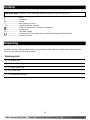
1
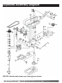
TDP330
350W 5 Speed Drill Press
ACL Group (Intl) Ltd
Email: [email protected]
www.terratekintl.com
User Manual — Please read and retain for future reference
1
Contents
Parts List
Technical Information
Safety Instructions
Using your Tool
Maintenance
Warranty
2
Part List
No.
1
2
3
4
5
6
7
8
9
10
11
12
13
14
15
16
17
18
19
20
21
22
23
24
25
26
27
27-1
Description
Base
Column Support
Washer
Bolt
Column
Clamping Lever
Bolt
Spring Washer
Working Table
Clamping Sleeve
Body
Headless Set Screw
Nut
Feed Shaft
Handle Bar
Knob
Headless Set Screw
Shifter Bar
Spring
Slide Bar
Rubber Pad
Bolt
Washer
Motor Base
Washer
Bolt
Motor
Capacitor Box
No.
41
42
43
44
45
46
47
48
49
50
51
52
53
54
55
56
57
58
59
60
61
62
63
64
65
66
67
68
Description
Plug
Screw
Rubber Tube
Fixed Plate
Nut
Screw
Fixed Plate
Nut
Nut
Spring Set
Spring Cap
Pointer
Nut
Nut
Limit Bolt
Chuck Guard
Nut
V-Belt
Spindle Pulley
Headless Set Screw
Retaining Ring
Internal Spine Sleeve
Retaining Ring
Ball Bearing
Ball Bearing
Retaining Ring
Retaining Ring
Ball Bearing
2
ACL Group (Intl) Ltd
Email: [email protected]
www.terratekintl.com
No.
27-2
28
29
30
31
32
33
34
35
36
37
38
39
40
Description
Capacitor
Motor Pulley
Headless Set Screw
Washer
Screw
Screw
Washer
Knob
Pulley Cover
Washer
Magnetic Switch
Screw
Cable
Plastic Clip
No.
69
70
71
72
73
74
75
76
77
78
79
80
81
82
Description
Collar
Spindle Sleeve
Ball Bearing
Spindle
Chuck
Screw
Switch Box
Micro Switch
Screw
Plate
Screw
Screw
Washer
Pressing Paw
3
ACL Group (Intl) Ltd
Email: [email protected]
www.terratekintl.com
Exploded Assembly Diagram
NOTICE: Actual product may vary from pictures shown.
4
ACL Group (Intl) Ltd
Email: [email protected]
www.terratekintl.com
7
16
20
15
8
6
14
11
10
9
13
4
2
1
Fig.1
5
ACL Group (Intl) Ltd
Email: [email protected]
www.terratekintl.com
Components and Controls (Fig.1)
1. Machine base
2. Pillar
3. Fixing screw
4. Drill table
5. Clamping screw
6. Machine head
7. V-belt cover
8. Motor
9. Handle grips
10. Scroll chuck
11. Spindle
12. Mounting holes
13. Hinged chip guard
14. Depth stop
15. Depth pointer
16. Screw
17. Cable
18. On switch
19. Off switch
20. Tightening screw
21. Allen key
22. Chuck key
6
ACL Group (Intl) Ltd
Email: [email protected]
www.terratekintl.com
3
Technical Information
Model: TDP330
Nominal input voltage: 230V ~/ 50 Hz
Power rating: 350 W
Operating mode: S2 15 min.
Motor speed: 1400 min-1
Output speed: 580 – 2.650 min-1
Speed levels: 5
Drill chuck mount: B16
Scroll chuck: Ø 1.5 - 13 mm
Max. drilling capacity: Ø 13 mm
Throat: 104 mm
Drill depth: 50 mm
Pillar diameter: 46 mm
Base size: 314 x 200 mm
Distance Spindle/Table: 200 mm
Distance Spindle/Base: 290 mm
Height: 580 mm
Weight: 18 kg
LPA sound pressure level in idle mode: 61,5 dB(A)
LWA sound power level in idle mode:74,5 dB(A)
Technical and visual enhancements may be made without prior notice. All dimensions, notes
and specifications contained in these operating instructions are therefore subject to change.
Hand/arm vibration is typically less than 2.5 m/s2.
Noise and vibration were determined in accordance with EN 61029-1 requirements.
7
ACL Group (Intl) Ltd
Email: [email protected]
www.terratekintl.com
Read this entire manual before using this product.
Failure to do so can result in serious injury. Save this manual for
future reference.
Copyright© 2013 by ACL Group (Intl) Ltd. All rights reserved. This manual or any artwork
contained herein must not be reproduced in any shape or form without the express
written consent of ACL Group (Intl) Ltd. Diagrams within this manual may not be drawn
proportionally. Due to continuing improvements, actual product may differ slightly from the
product described herein.
8
ACL Group (Intl) Ltd
Email: [email protected]
www.terratekintl.com
Read and Keep This Manual
Please read carefully all instructions within this manual. Failure to follow all safety warnings
can result in serious personal injury. The term “Power Tool” in all of the following warnings
refers to your mains operated (corded) or battery operated (cordless) power tool
Important SAFETY Information
This symbol is to warn you of potential personal injury
hazards. Please read carefully the notes along side this warning to
avoid possible injury or death.
General Safety Rules
WARNING! Read all instructions. Failure to follow all instructions listed
below may result in electric shock, fire and/or serious injury. The term “power tool” in all of
the warnings listed refers to corded or cordless power tools.
Work area safety
Keep work area clean and well lit. Cluttered or dark areas invite accidents.
Do not operate power tools in explosive atmospheres, such as in the presence of flammable
liquids, gases or dust. Power tools create sparks which may ignite the dust or fumes.
Keep children and bystanders away while operating a power tool. Distractions can cause you
to lose control.
9
ACL Group (Intl) Ltd
Email: [email protected]
www.terratekintl.com
Electrical safety
Before use, ensure that the power outlet you are using matches the plug on your power tool
and that the voltage of the outlet matches that of your power tool.
Only use grounded extension cords with power tools fitted with proper plugs and if using
outdoors ensure any extension cord is suitable for outdoor use.
Always try to avoid body contact with grounded surfaces, such as radiators, cooking ranges
and any other fixed appliance with metal surfaces.
Do not expose your power tool to wet or damp conditions and NEVER use in rain.
Check regularly the power cord of your machine and any extension cord that you are using
for damage.
Do not carry or pull the machine with the power cord.
Ensure the cord is clear from hot surfaces, oil or sharp objects.
Personal safety
Never use your power tool whilst under the influence of alcohol, drugs or medication.
Tiredness can often cause accidents, stay alert.
Never use your power tool without the correct guards in place.
Always use ANSI approved eye protection and dust mask. Non slip safety shoes and hearing
protectors should be worn at all times when using your power tool.
Ensure any dust collecting device supplied with your power tool is connected correctly before
use.
Ensure all loose clothing, long hair or jewelry is kept clear of the power tool.
Before plugging your power tool into the power outlet ensure the power tool is in the OFF
position.
Check that wrenches or adjusting keys have been removed. Any wrench or key left attached
to a moving part can result in injury.
Power tool use and care.
Keep your power tool clean and well serviced at all times.
Never adjust or service any power tool before disconnecting from the mains electricity supply.
Always use the correct tool for the job.
Never force the tool to work harder than it is designed to do.
Never use your power tool with broken parts such as switches, guide fences or leg stands.
ALWAYS keep your power tools away from children.
Keep cutting tools sharp to ensure less stress on the motor.
Only have your power tool serviced by a qualified repair agent using manufacturers
recommended parts.
10
ACL Group (Intl) Ltd
Email: [email protected]
www.terratekintl.com
WARNING:
For your own safety read Instruction Manual before operating your tool.
4
Safety Instructions
Warning! When using electric tools, basic safety precautions
should always be followed to reduce the risk of fire, electric shock
and personal injury, including the following.
Read all these instructions before attempting to operate this
product and safe these instructions.
1. Keep work area clean
– Cluttered areas and benches invite injuries.
2. Consider work area environment
– Don’t expose power tools to rain. Don’t use power tools in damp or wet locations. Keep
work area well lit. Don’t use power tools in presence of flammable liquids or gases.
3. Guard against electric shock
– Prevent body contact with grounded surfaces (e.g. pipes, radiators, ranges
refrigeratiors ).
4. Keep children away
– Do not let visitors contact tool or extension cord. All visitors should be kept away from
work area.
5. Store idle tools
– When not is use, tools should be stored in dry, high, or locked-up place, out of the reach
of children.
6. Don’t force tool
– It will do the job better and safer at the rate for which it was intended.
7. Use right tool
– Don’t force small tools or attachments to do the job of heavy duty tool. Don’t use tools
for purposes not intended: for example, don’t use circular saw for cutting tree limbs or
logs.
8. Dress properly
– Do not wear loose clothing or jewelry. They can be caught in moving parts. Rubber
gloves and nonskid footwear are recommended when working outdoors. Wear protective
covering to contain long hair.
9. Use safety glasses
– Also use face or dust mask if cutting operation is dusty.
10. Don’t abuse cord
– Never carry tool by cord or yank it to disconnect it from receptacle. Keep cord from
heat, oil and sharp edges.
11. Secure work
– Use clamps or a vise to hold work. It’s safer than using your hand and it frees both
hands to operate tool.
12. Don’t overreach
– Keep proper footing and balance at all times.
11
ACL Group (Intl) Ltd
Email: [email protected]
www.terratekintl.com
13. Maintain tools with care
– Keep tools sharp and clean for better and safer performance. Follow instructions for
lubricating and changing accessories. Inspect tool cords periodically and, if damaged,
have repaired by authorized service facility. Inspect extension cords periodically and
replace if damaged. Keep handles dry, clean and free from oil and grease.
14. Disconnect tools
– When not in use, before servicing, and when changing accessories such as blades, bits
and cutters.
15. Remove adjusting keys and wrenches
– Form the habit of checking to see that keys and adjusting wrenches are removed from
tool before turning it on.
16. Avoid unintentional starting
– Don’t carry plugged-in tool with finger on switch. Be sure switch is off when plugging in.
17. Outdoor use extension cords
– When tool is used outdoors, use only extension cords intended for use outdoors and so
marked.
18. Stay alert
– Watch what you are doing. Use common sense. Do not operate tool when you are tired.
19. Check damaged parts
– Before further use of the tool, a guard or other part that is damaged should be carefully
checked to determine that it will operate properly and perform its intended function.
Check for alignment of moving parts, binding of moving parts, breakage of parts,
mounting, and any other conditions that may affect its operation. A guard or other part
that is damaged should be properly repaired or replaced by an authorized service center
unless otherwise indicated elsewhere in this instructions manual. Have defective switches
replaced by an authorized service center. Do not use tool if switch does not turn it on and
off.
20. Warning
– The use of any other accessory or attachment other than recommended it this operating
instruction may present a risk of personal injury.
21. Have your tool repared by an expert
– This electric appliance is in accordance with the relevant safety rules repairing of
electric appliances may be carried out only by experts otherwise it may cause
considerable danger for the user.
22. Connect the dust extraction device
– Wherever there are facilities for fitting a dust extraction system, make sure it is
connected and used.
Special safety instructions for Bench Press
The bench press was designed in such a way so as to all but eliminate potential hazards when
the machine is properly used. However, there are a few safety precautions to observe in order
to ensure that all residual hazards are ruled out.
1. Ensure proper voltage
The voltage must comply with the specifications on the rating plate.
2. Use a socket-outlet with earthing contact
The device may only be operated from an outlet with the properly installed earthing
contact.
3. Extension cable
The cord cross section of an extension cable must measure at least 1.5 mm2. Always
completely unwind a cable reel prior to use. Check the cable for defects.
12
ACL Group (Intl) Ltd
Email: [email protected]
www.terratekintl.com
4. Protection against electrical shock
Keep the device away from moisture. The device must neither be damp nor be operated in
a humid environment. Prior to every use, check the device and the mains cable with plug
for damage. Avoid bodily contact with earthed parts e.g. pipes, hot elements, etc.
5. Protection against fire and explosion
There are spark producing components inside the device. Do not use the device in the
vicinity of combustible liquids or gases. Otherwise there is a risk of fire or explosion.
6. Handle the device with care
Do not use the cable to pull the plug out of the socket. Protect the cable from heat, oil
and sharp edges. Keep your tools sharp and clean so that you can work efficiently and
safely. Follow the maintenance regulations and the instructions for changing tools.
7. Wear suitable work clothes and personal protection equipment
Loose clothing is not suitable, as it can be caught by moving parts, causing you to become
entangled.
Wear a hair net if you have long hair. As a general rule, jewelry should not be worn when
working with machine tools. Ensure that you wear safety goggles. Not doing so could result
in eye injury.
8. Keep your work area neat and tidy
Disorder in the work area can easily lead to accidents. Do not leave any tools, objects, or
cable in the direct vicinity of the work area, as this poses a tripping hazard! Ensure that
there is sufficient lighting.
9. Watch out for other persons
Watch out for other persons (especially children) when using the device, and keep them
away from your work area. Do not let anyone touch the device or the power cable.
10. Store the tools in a safe location
Store unused devices in a dry, locked location that is out of the reach of children.
11. Avoid overloading the device
Operate the device only within the specified output range. Do not use any low-powered
machines for heavy duty work. Do not use tools to perform work for which they were not
intended.
12. Maintain a steady foothold
Ensure that you maintain a steady foothold while working. Avoid abnormal body positions
and always keep your balance.
13. Pull out the mains plug
Pull out the mains plug when not using the tool, prior to maintenance, and when changing
the drill bit.
14. Pull out the power plug.
Ensure that the mains connection is protected by at least a 10 A-rated fuse.
15. Avoid unintentional start-up
Ensure that switch is turned off when plugging the plug into the socket.
16. Keep an eye on your work
Always keep an eye on your machine and the object you are working on. Never use the
machine when you are not concentrating or are distracted. Never use the machine when
you are under the influence of alcohol or are taking medication.
17. Check the tool for damage
Before using the tool, safety devices and any slightly damaged parts must be carefully
checked to ensure that they are in good working order. Visually examine the tool’s power
cable on a regular basis. All parts must be correctly assembled and meet all the
conditions required to ensure proper operation.
Unless otherwise specified in the operating instructions, any damaged safety devices and
parts must be properly repaired or replaced by a professionally recognized workshop.
Never use tools with defective On/Off switches.
13
ACL Group (Intl) Ltd
Email: [email protected]
www.terratekintl.com
Warning! Using any plug-in tools and accessories other than those specified in these
operating instructions can lead to injury.
Now, please read and follow all steps and procedures included in the operating
instructions.
Only use qualified repair agents to service this power tool.
Only use qualified electrician to repair any damaged wiring.
NEVER remove the grounding prong from the power toll or extension cord.
Power Extension Cords
When using any extension cord the machine will suffer a power reduction due to the drop in
voltage caused by the length of the cord. This can be partially offset by selecting extension
cords with lower gauge wire.
Check all extension cords for damage before use.
Avoid sharp objects.
Do not position the cord where it could be subject to traffic passing over it.
14
ACL Group (Intl) Ltd
Email: [email protected]
www.terratekintl.com
Symbols
IMPORTANT: Some of the following symbols may be used on your tool.
V…………………………volts
A…………………………amperes
Hz……………………….hertz
~…………………….….alternating current
…/m……………….....revolutions per minute
……………….......class II construction (double insulated)
Kg……………………….kilograms
n0………….…………...No load speed
…………………..…Conforms to European Harmonised New Approach Directives
DC ………………..…..Direct Current
Unpacking
Carefully remove the product and any accessories from the box. Make sure that all items
listed in the packing list are included.
Packing List
A) 1 x Bench Drill
B) 1 x 3mm Allen Key
C) 1 x 4mm Allen Key
D) 1 x Chuck Key
E) 1 x Instruction Manual
15
ACL Group (Intl) Ltd
Email: [email protected]
www.terratekintl.com
5
Using your Tool
Assembly (Fig. 1-4)
Assemble the machine as follows:
1. Position the machine base (1).
2. Fasten the mounting flange with pillar (2) to machine base (1) using three screws (3) and
washers.
3. Push the drill table (4) with drill table clamp shaft onto the pillar (2) (Fig. 4).
4. Lock the drill table into the desired position using the clamping screw (5).
5. Place the drill head (6) with V-belt cover (7) and motor (8) onto the drill pillar and fasten
using the grub screw (20).
6. Screw the three ball-shaped handles (9) onto the feeder cross handle.
7. Mount the drill chuck onto the spindle.
Note: All bare parts are greased in order to protect them from corrosion. Before mounting
the drill chuck (10) onto the spindle (11), both parts must be completely degreased using an
environmentally friendly solvent. This ensures optimal transmission of power.
7
2
1
6
8
3
17
10
4
22
9
13
21
Fig.2
16
ACL Group (Intl) Ltd
Email: [email protected]
www.terratekintl.com
19 18
5
4
2
1
3
Fig.3
Fig.4
Installing the machine (Fig. 1/2)
Before the drill is started for the first time, it must be solidly and fully mounted on the work
area of a stable workbench. Use both mounting holes (12) in the base plate to do this. Ensure
that the machine is freely accessible for operation, adjustment and maintenance.
Note: The fixing screws may only be tightened to a point where they do not distort or deform
the base plate. Excessive tension can lead to fracture.
Hinged chip guard (Fig. 5)
Unscrew the three recessed head screws (25).
Push the transparent cover (23) into the groove of the red mounting frame (24) and fasten it
again with the recessed head screws (25).
The height of the cover (23) is infinitely adjustable and can be locked using the two thumb
screws (27).
The chip guard (13) can be flipped upwards to change drill bits; ensure, however, that the
chip guard (13) is back in its initial position before restarting the machine.
24
25
27
23
Fig.5
17
ACL Group (Intl) Ltd
Email: [email protected]
www.terratekintl.com
Prior to starting
Ensure that the voltage of the mains supply complies with the specifications on the rating
plate. Connect the machine only to a socket with the properly installed earthing contact.
The table drill is equipped with a no-volt trip that is designed to protect the operator from an
undesired restart following a drop in voltage. Should this occur the machine must be manually
restarted.
Operation
Operation
Wear suitable, protective clothing (i.e. rugged and tight-fitting) when working with
the table drill. Always wear safety goggles! Long hair should always be bound back
with a hair net or a cap!
General (Fig. 3)
To switch on the machine, push in the green On button “I” (18); the machine starts up. To
switch off, press the red Off button “O” (19); the device shuts down. Ensure that you do not
overload the device. If the sound of the motor drops in pitch during operation, it is being
overloaded. Do not overload the device to the point where the motor comes to a standstill.
The machine is designed for continuous operation with intermittent load (S2 15 min.).
The machine may be operated under a full load for a maximum of 15 minutes, at which time
the machine needs to idle for 15 minutes. This prevents the motor from overheating.
Inserting the tool (Fig. 1/2)
Make sure that the power plug is removed from the socket-outlet before changing tools. Only
cylindrical tools with the stipulated maximum shaft diameter may be clamped in the scroll
chuck (10). Only use a tool that is sharp and free of defects. Do not use tools whose shaft
is damaged or which are deformed or flawed in any other way. Use only accessories and
attachments that are specified in the operating instructions or have been approved by the
manufacturer.
Handling the drill chuck (Fig. 1/2)
Your table drill is equipped with a scroll chuck (10). In order to insert a drill bit, flip up the
chip guard (13), insert the drill bit, then tighten down the drill chuck using the supplied chuck
key. Pull out the chuck key. Ensure that the clamped in tool is firmly seated.
Caution! Do not leave the chuck key in the clamp hole.
Doing so will cause it to shoot out, which could cause injury.
Setting the speed (Fig. 1/2/7/8)
First switch the machine off, then pull out the mains plug.
The various spindle speeds can be set by moving the V-belt.
Proceed as follows:
1. Remove the screw (16) in order to open the V-belt cover (7).
2. Slacken the tightening screw (20) and push the motor (8) in the direction of the machine
head.
3. Move the V-belt to the desired position.
4. Refer to the table for the recommended speeds for different drill bit materials (Fig. 7/10).
5. Tighten the V-belt by pushing the motor (8) back from the machine head (6). Screw the
tightening screw (16) back down again. The tension is properly set when the V-belt flexes
in the middle by approx. 1 cm when pressed.
6. Close the V-belt cover and screw down using the screw (16). The V-belt cover (7) must
always be locked tight, as the machine is equipped with a safety switch that only allows
18
ACL Group (Intl) Ltd
Email: [email protected]
www.terratekintl.com
the machine to be turned on when the V-belt cover (7) is closed.
Caution! Never let the bench press run when the V-belt cover is open. Always pull the mains
plug before opening the cover. Never touch the V-belt when it is rotating.
Fig.7
16
14
15
Fig.9
Fig.8
Drill depth stop (Fig. 9)
The drill depth can be set exactly by means of the depth stop (14) and a scale (a) on the
front side of the machine head. The machine must be switched off in order to set the depth
stop.
1. Insert the required bit (See above section) and turn the setting screws up.
2. Using the handle, move the bit so that its tip just touches the surface of the workpiece and
read the value indicated on the scale.
3. Remove the workpiece.
4. Add the required drill depth to the value you read off the scale and use the handle to lower
the bit until the value you calculated is indicated on the scale.
5. Turn down the lower setting screw as far as it will go.
6. Secure the setting by turning the upper setting screw against the lower setting screw.
Important! When setting the drill depth of a cylindrical hole you must add the length of the
drill tip
Setting the angle of the drill table (Fig. 6)
1. Slacken the carriage bolt (26) under the drill table (4).
2. Set the drill table (4) to the desired angle (which can be read off the scale on the top side
of the drill table).
19
ACL Group (Intl) Ltd
Email: [email protected]
www.terratekintl.com
3. Tighten down the carriage bolt (26) in order to lock the drill table (4) into this position.
4
26
Fig.6
Setting the height of the drill table (Fig. 1/2)
1. Slacken the tightening screw (5).
2. Set the drill table (4) to the desired height by pressing down or lifting up and
simultaneously (gently) pushing to the left or right.
3. Screw the tightening screw (5) back down again.
Locking the workpiece into position (Fig. 1)
As a general rule, use a machine vice (14) or another suitable clamping device to lock a
workpiece into position.
Never hold the workpiece in place with your hand!
When drilling, the workpiece should be able to travel on the drill table (4) for self-centering
purposes.
Ensure that the workpiece cannot rotate. This is best achieved by placing the workpiece/
machine vice on a sturdy block.
Caution! Sheet metal parts must be clamped in to prevent them from being torn up. Properly
set the height and angle of the drill table for each workpiece.
There must be enough distance between the upper edge of the workpiece and the tip of the
drill bit.
Drilling wood
Please note that sawdust must be properly evacuated when working with wood, as it can
pose a health hazard. Ensure that you wear a suitable dust mask when performing work that
generates dust.
Working speeds
Ensure that you drill at the proper speed. Drill speed is dependent on the diameter of the drill
bit and the material in question.
The table below acts as a guide for selecting the proper speed for various materials.
Note: The drill speeds specified are merely suggested values.
20
ACL Group (Intl) Ltd
Email: [email protected]
www.terratekintl.com
Countersinking and center-drilling
With this table drill, you can also countersink and center-drill. Please observe that
countersinking should be performed at the lowest speed, while a high speed is required for
center-drilling.
21
ACL Group (Intl) Ltd
Email: [email protected]
www.terratekintl.com
6
Maintenance
The bench drill is to a large extent maintenance-free.
Keep the device clean.
Pull out the mains plug before doing any cleaning and maintenance work on the machine.
Do not use any harsh, abrasive cleaning solvents.
Ensure that no liquid seeps into the device.
Regrease all bare parts when the work is finished.
The bench press, blank parts of the column, and the drill table especially should be regreased
at regular intervals. Use a standard, acid-free lubricating grease to do this.
Caution: Do not use your household refuse bin as a receptacle for oil and grease-soaked
cleaning rags or grease and oil sludge. Dispose of these toxic materials in an environmentallyfriendly fashion.
Regularly check and clean the ventilation holes.
Store the device in a dry room. Should the device become damaged, do not try to repair it
yourself; leave this work to the hands of a qualified electrical technician.
Disposal
Power tools, accessories and packaging should be sorted for environmentally-friendly
recycling.
Only for EC countries:
Do not dispose of power tools into household waste!
According to the European Directive 2002/96/EC on waste electrical and
electronic equipment and its incorporation into national right, products
that are no longer suitable for use must be separately collected and sent
for recovery in an environmentally-friendly manner.
22
ACL Group (Intl) Ltd
Email: [email protected]
www.terratekintl.com
We ACL Group (Intl.) Ltd, England DN6 8LZ declare that the bench drill has been
manufactured according to our full quality assurance procedures.
The declaration is to certify that it conforms to CE, EMC, LVD, MD and RoHS directives:
EN55014-1/A1:2009
EN55014-2/A2:2008
EN61000-3-2/A2: 2009
EN61000-3-3: 2008
All provisions of Annex 1 of Council Directive 2004/108/EC – EMC directive
EN61029-1/A11: 2010
EN ISO 12100: 2010
All provisions of Annex 1 of Council Directive 2006/42/EC – the Machinery Directive
2006/95/EC – the Low Voltage Directive
RoHs 2011/65/EU
Mr. Alan Garnett, UK QA Manager
Environmental Protection
RECYCLING: WASTE ELECTRICAL PRODUCTS SHOULD NOT BE DISPOSED OF WITH
HOUSEHOLD WASTE. PLEASE RECYCLE WHERE FACILITIES EXIST. CHECK WITH YOUR LOCAL
AUTHORITY OR RETAILER FOR RECYCLING ADVICE.
23
ACL Group (Intl) Ltd
Email: [email protected]
www.terratekintl.com
7
Warranty
Please read the following carefully
ACL Group (Intl) Ltd. and/or it’s distributor has provided the parts list and assembly
diagram as a reference tool only. Neither ACL Group (Intl). Ltd. or its distributor makes any
representation or warranty of any kind to the buyer that he or she is qualified to do any
repairs or replace any parts of this product. ACL Group (Intl) Ltd. and its distributor expressly
state that all repairs or parts replacement should be done by certified or licensed technicians.
The buyer assumes all risk and liability arising out of his or her repairs or parts replacement
to the original product.
12 Months Limited Warranty
If within 12 months from the date of purchase you experience any problems with your
product, please return the product to its distributor/dealer for repair or replacement. This
warranty DOES NOT COVER normal wear, or any damage as a result of accidents, misuse,
abuse or negligence.
24
ACL Group (Intl) Ltd
Email: [email protected]
www.terratekintl.com
ACL Group (Intl) Ltd
Email: [email protected]
www.terratekintl.com