1
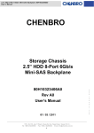
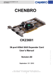
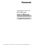
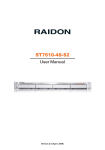
SK32303 ver. B0
User’s Manual
CHENBRO
User’s Manual
SK32303
Version B0
July / 30 / 2008
15Fl., No.150, Jian Yi Road, Chung Ho City, Taipei Hsien, Taiwan R.O.C.,
Tel: +886 2 82265500 Fax: +886 2 82265392 Email: [email protected]
1
w w w . c h e n b r o . c o m
2-to-3 SATA / SAS HDD
Storage Kit
SK32303 ver. B0
User’s Manual
Copyright
Copyright © 2006 CHENBRO Micom Co., Ltd.. All rights reserved.
Unless otherwise indicated, all materials in this manual are copyrighted by CHENBRO Micom Co., Ltd.. All rights
reserved. No part of this manual, either text or image may be used for any purpose other than internal use within
purchasing company. Therefore, reproduction, modification in any form or by any means, electronic, mechanical or
otherwise, for reasons other than internal use, is strictly prohibited without prior written permission.
CHENBRO Micom Co., Ltd. reserves the right to make improvement and modification to the products indicated in
this manual at any time. Specifications are therefore subject to change without prior notice.
Information provided in this manual is intended to be accurate and reliable. However, CHENBRO Micom Co., Ltd.,
assumes no responsibility for its use, nor for any infringements upon the rights of third parties, which may result from
its use.
Technical Support
CHENBRO works hard to offer our customers maximum performance from our chassis. But in case you
have any problem with our product you can find supports from the following resources.
Web Support
Detail information of our products is in our website. You can find technical updates, installation guides, FAQs,
Technical specifications and more. Our web address is: www.chenbro.com.
Email Support
You can also fill out the technical support form at our Technical Support page. You technical issue inquiries will be
sent directly to our support professionals.
Phone Support
following:
CHENBRO HQ
CHENBRO Europe B.V.
CHENBRO Micom (USA) Inc.
Tel: 886-2-8226-5500
Tel: 31-40-295-2045
Tel: 1-909-947-3200
Fax: 886-2-8226-5423
Fax: 31-40-295-2044
Fax : 1-909-947-4300
15Fl., No.150, Jian Yi Road, Chung Ho City, Taipei Hsien, Taiwan R.O.C.,
Tel: +886 2 82265500 Fax: +886 2 82265392 Email: [email protected]
2
w w w . c h e n b r o . c o m
You can also contact CHENBRO HQ or branch office for immediate support; their contact Information is as
SK32303 ver. B0
User’s Manual
Contents
15Fl., No.150, Jian Yi Road, Chung Ho City, Taipei Hsien, Taiwan R.O.C.,
Tel: +886 2 82265500 Fax: +886 2 82265392 Email: [email protected]
3
w w w . c h e n b r o . c o m
Copyright......................................................................................................................................................2
Technical Support......................................................................................................................................2
Contents .......................................................................................................................................................3
Revision History.........................................................................................................................................4
Safety Information .....................................................................................................................................5
Conventions Used in this Manual..........................................................................................................5
Getting Start with the SK32303 Storage Kit ........................................................................................6
Unpacking and Checking the Contents .......................................................................................6
Technical Specifications ..........................................................................................................................6
Compatible CHENBRO Chassis.............................................................................................................6
Introduction .................................................................................................................................................7
Functional Specification ..........................................................................................................................7
General..................................................................................................................................................7
Host / Drive / Power Backplane Interface ....................................................................................7
Monitoring Function..........................................................................................................................7
Mechanical Dimension .............................................................................................................................8
Components Description.........................................................................................................................9
Front View ............................................................................................................................................9
Rear View – with Cover...................................................................................................................10
Rear View – Cover Removed.........................................................................................................11
Connector & Switch Definition.............................................................................................................12
HDD Failure Signal Connector .....................................................................................................12
Setting for HDD Failure Signal Cable Connection (SK32303 Backplane)................ 12
Setting for HDD Failure Signal Cable Connection (RAID Card) ................................. 12
HDD Activity Signal Jumper..........................................................................................................13
Default setting for SATA-II HDD........................................................................................... 13
Setting for SATA-I HDD (SK32303 Backplane) ................................................................ 13
Setting for SATA-I HDD (RAID Card) .................................................................................. 13
SATA or SAS HDD access LED signal auto selection............................................................14
Installation Procedures ..........................................................................................................................16
Hot-swap HDD Assembly...............................................................................................................16
Remove Rear Cover ........................................................................................................................17
Relative Part Number List......................................................................................................................18
SK32303 ver. B0
User’s Manual
Revision History
Date
July / 30 / 2008
Modifications
z First Release
w w w . c h e n b r o . c o m
15Fl., No.150, Jian Yi Road, Chung Ho City, Taipei Hsien, Taiwan R.O.C.,
Tel: +886 2 82265500 Fax: +886 2 82265392 Email: [email protected]
4
SK32303 ver. B0
User’s Manual
Safety Information
z Read the installation instructions before connecting SK32303 to the power source.
z Only trained and qualified personnel should be allowed to install, replace or service this equipment.
z Never install this product in a wet environment.
z Position system cables and power cables carefully; route system cable and the power cable and plug so
that they cannot be stepped on or tripped over. Be sure that nothing rests on your system components’
cables or power cable.
Conventions Used in this Manual
The following conventions are used in this manual.
Note Icon:
Provides more information on the current topic.
Important Icon:
Provides important information on the current topic that must not be overlooked.
w w w . c h e n b r o . c o m
15Fl., No.150, Jian Yi Road, Chung Ho City, Taipei Hsien, Taiwan R.O.C.,
Tel: +886 2 82265500 Fax: +886 2 82265392 Email: [email protected]
5
SK32303 ver. B0
User’s Manual
Getting Start with the SK32303 Storage Kit
Thank you for purchasing SK32303! This section covers unpacking and identifying components.
Unpacking and Checking the Contents
The complete SK32303 package includes the following items:
Item Description
Quantity
SK32303 Storage Cage
1
Hot-swap 3.5” Hard Disk Drive (HDD) Tray
3
SAS / SATA-II cable
3
HDD failure / activity signal Cable
1
Screw: #6-32 (6mm) for tray and HDD assembling
12
Screw: M3 (6mm) for Storage Cage and chassis assembling
6
The HDD failure / activity signal cable (26H113215-005) is available for using on
HDD failure or activity LED.
Refer to the RAID card user manual for the detailed application and connection
information.
Technical Specifications
Occupancy
2 x 5.25” Drive Bays
Capacity
3 x SATA-I, II or SAS Hot-swap HDDs
Cooling Subsystem
1 x 60mm (Thickness 25mm) Exhaust Fan
Fan Failure LED and Alarm
System Monitoring
Overheat LED and Alarm
HDD Failure LED and Alarm
Weight (fan included)
146 x 84.5 x 218.7 (mm)
5.75 x 3.32 x 8.61 (inch)
1.4 kg
Compatible CHENBRO Chassis
z RM21600 / RM31300 / RM31408
RM41100 / RM41500 / RM42200
z SR105 / SR107 / SR108 / SR201 / SR209
z PC617
15Fl., No.150, Jian Yi Road, Chung Ho City, Taipei Hsien, Taiwan R.O.C.,
Tel: +886 2 82265500 Fax: +886 2 82265392 Email: [email protected]
6
w w w . c h e n b r o . c o m
Dimension (WxHxD)
SK32303 ver. B0
User’s Manual
Introduction
The CHENBRO SK32303 can house three 3.5” HDDs in a two 5.25” bays converter (Depth of 9.5”
recommended). The ability for conversion allows existing servers to perform the maximum HDD density
while keeping the flexibility. In all, SK32303 is the best solution as value added feature and performance.
Functional Specification
General
z Support up to SATA-II and SAS (3.0 Gb/s)
z Compatible with 3.5” SAS, SATA-I and SATA-II HDD
z Support inrush current control for HDD Hot-swapping
z LED indicate activity and failure for each HDD
z Alternative HDD activity and failure signal source
Host / Drive / Power Backplane Interface
z Direct link SATA / SAS ports
z 3 x SATA Signal + Power (7+15 pin) connectors at HDD side of backplane
z 3 x SATA interfaces (7 pin)
z 2 x DC power connectors (4-pin D-type)
Monitoring Function
z 1 x Fan connector with speed monitoring
z 2 x temperature sensors for HDD overheating monitoring
z Alterable overheat temperature: 55 ℃ or 65 ℃
z Support 1 x buzzer for audible alarm, 3 x LED for overheat, fan & HDD failure indicator, 1 x alarm mute
button for disabling audible alarm
w w w . c h e n b r o . c o m
15Fl., No.150, Jian Yi Road, Chung Ho City, Taipei Hsien, Taiwan R.O.C.,
Tel: +886 2 82265500 Fax: +886 2 82265392 Email: [email protected]
7
SK32303 ver. B0
User’s Manual
Mechanical Dimension
w w w . c h e n b r o . c o m
15Fl., No.150, Jian Yi Road, Chung Ho City, Taipei Hsien, Taiwan R.O.C.,
Tel: +886 2 82265500 Fax: +886 2 82265392 Email: [email protected]
8
SK32303 ver. B0
User’s Manual
Components Description
Front View
2. HDD power LED
HDD 1
HDD 2
4. Alarm mute button
5. Overheat warning LED
HDD 3
6. Fan failure LED
7. HDD failure LED
1. 3.5” HDD Hot-swap Tray
3. HDD activity / failure LED
Device
Function
1
3.5” HDD Hot-swap Tray
Refer to Page 15
2
HDD Power LED
Blue LED On - HDD Power On
3
HDD activity / failure LED
4
Alarm mute button
Click to stop the system failure alarm
5
Overheat Warning LED
Red LED On - Temperature overheat
6
Fan failure LED
Red LED On - Fan failure
7
HDD failure LED
Red LED On - HDD failure
Green LED On - HDD active
Red LED On - HDD failure
9
w w w . c h e n b r o . c o m
15Fl., No.150, Jian Yi Road, Chung Ho City, Taipei Hsien, Taiwan R.O.C.,
Tel: +886 2 82265500 Fax: +886 2 82265392 Email: [email protected]
SK32303 ver. B0
User’s Manual
Rear View – with Cover
2. Power connectors
HDD 1
HDD 2
HDD 3
3. Buzzer
1. SATA / SAS connectors
7. 60mm fan
4. HDD activity signal jumper
5. HDD failure signal connector
6. Fan connector
Function
1
SATA / SAS HDD Connectors
Connect to motherboard / RAID card
2
Power Connectors
Power input
3
Buzzer
Alarm for system failure
4
HDD activity signal jumper
Refer to Page 13
5
HDD failure signal connector
Refer to Page 12
6
Fan connector
Connect to 60mm fan
7
60mm Fan
Air mover for SK32303 storage kit
15Fl., No.150, Jian Yi Road, Chung Ho City, Taipei Hsien, Taiwan R.O.C.,
Tel: +886 2 82265500 Fax: +886 2 82265392 Email: [email protected]
10
w w w . c h e n b r o . c o m
Device
SK32303 ver. B0
User’s Manual
Rear View – Cover Removed
Fan & Temperature Switch
SATA or SAS HDD access LED
signal auto selection
Device
Function
Fan & Temperature Switch
Refer to Page 14
[CN8] SATA or SAS HDD access LED signal auto selection
Refer to Page 14
Refer to page 17 for rear cover removal.
w w w . c h e n b r o . c o m
15Fl., No.150, Jian Yi Road, Chung Ho City, Taipei Hsien, Taiwan R.O.C.,
Tel: +886 2 82265500 Fax: +886 2 82265392 Email: [email protected]
11
SK32303 ver. B0
User’s Manual
Connector & Switch Definition
HDD Failure Signal Connector
This connector is for the SATA RAID card with HDD failure signal support such as ARECA ARC-1230 & 1260.
Connect the failure signal connectors on SK32303 backplane and RAID card to activate the HDD failure LED.
Setting for HDD Failure Signal Cable Connection (SK32303 Backplane)
HDD 1
HDD 2
HDD 3
HDD LED Cable: 26H113215-005
Setting for HDD Failure Signal Cable Connection (RAID Card)
Connect the 4-pin HDD LED cable to the CATHODE of the HDD failure connector on RAID card. Refer to your
RAID card’s user manual for the detailed pin definition.
w w w . c h e n b r o . c o m
HDD 3
HDD 2
HDD 1
15Fl., No.150, Jian Yi Road, Chung Ho City, Taipei Hsien, Taiwan R.O.C.,
Tel: +886 2 82265500 Fax: +886 2 82265392 Email: [email protected]
12
SK32303 ver. B0
User’s Manual
HDD Activity Signal Jumper
The default jumpers are installed for SATA-II (3.0 Gb/s) HDDs which support activity signal via pin-11 of the
connector on HDD.
If using SATA-I (1.5 Gb/s) HDD, remove the jumper for HDD 1, 2 or 3 and connect the activity signal
connectors on SK32303 backplane and RAID card to activate the HDD activity LED. The RAID card must
support the HDD activity signal such as 3ware 8000 & 9000 series.
Default setting for SATA-II HDD
Setting for SATA-I HDD (SK32303 Backplane)
HDD LED Cable: 26H113215-005
HDD 3
HDD 2
HDD 1
Setting for SATA-I HDD (RAID Card)
Connect the 4-pin HDD LED cable to the CATHODE of the HDD activity connector on RAID card. Refer to
your RAID card’s user manual for the detailed pin definition.
w w w . c h e n b r o . c o m
HDD 1
HDD 2
HDD 3
15Fl., No.150, Jian Yi Road, Chung Ho City, Taipei Hsien, Taiwan R.O.C.,
Tel: +886 2 82265500 Fax: +886 2 82265392 Email: [email protected]
13
SK32303 ver. B0
User’s Manual
Fan & Temperature Switch
This switch is located behind the rear cover.
Switch 1: Enable / Disable the fan.
Switch 2: Change the threshold temperature of SK32303 storage kit
Switch 1: Fan Enable / Disable
1
Fan
Remark
ON
Enable
Default
OFF
Disable
Switch 2: Threshold Temperature Setting
2
Threshold Temperature
ON
65 ℃
OFF
55 ℃
Remark
Default
Refer to page 17 for rear cover removal.
SATA or SAS HDD access LED signal auto selection
This Jumper (CN8) is located behind the rear cover.
Jumper Closed: Enable auto selection
15Fl., No.150, Jian Yi Road, Chung Ho City, Taipei Hsien, Taiwan R.O.C.,
Tel: +886 2 82265500 Fax: +886 2 82265392 Email: [email protected]
14
w w w . c h e n b r o . c o m
Default setting
SK32303 ver. B0
User’s Manual
Jumper Opened: Disable auto selection. HDD access LED setting for SATA HDD only.
w w w . c h e n b r o . c o m
15Fl., No.150, Jian Yi Road, Chung Ho City, Taipei Hsien, Taiwan R.O.C.,
Tel: +886 2 82265500 Fax: +886 2 82265392 Email: [email protected]
15
SK32303 ver. B0
User’s Manual
Installation Procedures
The following is the installation procedures of HDD and rear cover assembly.
Hot-swap HDD Assembly
a. Push the blue latch of HDD tray and pull it out from the cage
b. Attach HDD with six screws per tray
w w w . c h e n b r o . c o m
c. Insert HDD tray to the cage
15Fl., No.150, Jian Yi Road, Chung Ho City, Taipei Hsien, Taiwan R.O.C.,
Tel: +886 2 82265500 Fax: +886 2 82265392 Email: [email protected]
16
SK32303 ver. B0
User’s Manual
Remove Rear Cover
a. Unplug fan connector and remove four screws on the cover
b. Remove rear cover
c. Backplane
w w w . c h e n b r o . c o m
15Fl., No.150, Jian Yi Road, Chung Ho City, Taipei Hsien, Taiwan R.O.C.,
Tel: +886 2 82265500 Fax: +886 2 82265392 Email: [email protected]
17
SK32303 ver. B0
User’s Manual
Relative Part Number List
CHENBRO
Part Number
Description
Unit
80H045323-001
SK32303 LED Board
pcs
80H105323-003
SK32303 3-Port SATA /SAS Backplane
pcs
26H123215-002
SAS / SATA-II Cable, 700mm
pcs
26H113215-005
HDD failure / activity signal Cable, 4P to 4P, 600mm
pcs
83H305223-001
60mm (Thickness 25mm), Ball Bearing Fan
pcs
83H555335-016
Hot-swap HDD Tray
pcs
Remark
w w w . c h e n b r o . c o m
15Fl., No.150, Jian Yi Road, Chung Ho City, Taipei Hsien, Taiwan R.O.C.,
Tel: +886 2 82265500 Fax: +886 2 82265392 Email: [email protected]
18