1
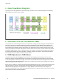
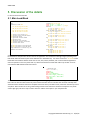
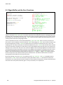
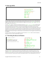
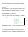
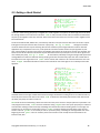
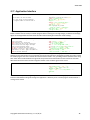
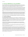
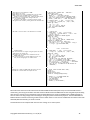
GreenArrays
®
AN001 MD5
Application Note AN001 Revised 10/23/14
Implementing MD5
on a GA144
MD5 is a well known cryptographic algorithm, calculating a one way hash function of 128 bits on an
arbitrarily long sequence of octets; it is a standard component of many cryptosystems including IPSec
and Public Key Infrastructures. There are many possible ways to implement such an algorithm on
GreenArrays chips; the implementation described in the first part of this document is the first we
have produced (written by staff member Charley Shattuck) and is written as machine code for a
cluster of F18 computers. This method generally leads to maximum speed, no dependency on
external memory or high level programming such as eForth, and may be adapted for commitment to
ROM if desired.
In this paper we describe the operation of the module and its interfaces. The text assumes you have
familiarized yourself with our hardware and software technology by reading our other documents on
those topics. The current editions of all GreenArrays documents, including this one, may be found on
our website at http://www.greenarraychips.com . It is always advisable to ensure that you are using
the latest documents before starting work.
Contents
1.
Overview .......................................................................................................................................... 2
1.1
Data Sources ........................................................................................................................................................................................ 2
2.
Green Arrays Architecture ................................................................................................................ 3
2.1
2.2
2.3
32 Bit Addition and Rotation ............................................................................................................................................................... 3
A Lookup Table with 64 32 bit Words .................................................................................................................................................. 3
Other Code and Data ........................................................................................................................................................................... 3
3.
Data Flow Block Diagram .................................................................................................................. 4
4.
Allocation of Code and Data for MD5 ................................................................................................ 4
4.1
4.2
4.3
32 Bit Operations in 16 Bit Halves ....................................................................................................................................................... 4
Layout .................................................................................................................................................................................................. 5
Beginning and Ending the Application ................................................................................................................................................ 5
5.
Discussion of the details ................................................................................................................... 6
5.1
5.2
5.3
5.4
5.5
5.6
5.7
5.8
5.9
5.10
5.11
Main Load Block .................................................................................................................................................................................. 6
Boot Descriptors .................................................................................................................................................................................. 7
Table Lookup ....................................................................................................................................................................................... 7
Adding and Rotating 32 Bit Words ...................................................................................................................................................... 9
Digest Buffer and the Four Functions ................................................................................................................................................ 10
Message Buffer.................................................................................................................................................................................. 11
Calculating the Amount of Rotation.......................................................................................................................................... 11
Initial Digest Buffer and Summation ................................................................................................................................................. 12
Getting a Hash Started ...................................................................................................................................................................... 13
Formatting the Input Stream............................................................................................................................................................. 14
Application Interface ......................................................................................................................................................................... 15
6.
Testing the MD5 Module using polyFORTH® ................................................................................... 16
6.1
Initiating the MD5 Hash .................................................................................................................................................................... 16
AN001 MD5
1. Overview
A definitive specification for the MD5 algorithm is published by the Internet Engineering Task Force as RFC 1321 and a
discussion of performance is available in RFC 1810 as well as tables in books such as Applied Cryptography by Bruce
Schneier. Incidentally, our own reference FORTH implementation running on a PC with 2.9 GHz modern Intel processor
hashes 1,000,000 bytes in 3.782 milliseconds for a hash speed of 2.12 gigabits per second.
MD5 presents a few problems for programming a Green Arrays device. For one thing it depends on modulo 32 bit
addition and rotation. Green Arrays chips deal in 18 bit quantities. For another, md5 is complicated enough that
neither the code nor the set of constants required to implement the algorithm will fit into one or even two or three
nodes of a Green Arrays computer. Let's see how to deal with that.
1.1 Data Sources
During each step of the MD5 algorithm there are three main sources of data and several numerical sequences for
accessing this data.
The first data source is the current state of the message digest, represented as ABCD. It contains 4 32 bit numbers.
Temporary storage for A, B, C, and D is required as well. Let's call that AA, BB, CC, and DD, each a 32 bit number. ABCD
is accessed in rotating fashion as ABCD, DABC, CDAB, BCDA, and so on as the algorithm proceeds.
The second data source is the message buffer, represented by X(k). The message is divided into blocks of 64 bytes or 16
32 bit words, indexed by the sequence represented by k. The message buffer is accessed in an order that is not linear,
but which can be calculated in less space than it can be listed in.
The third data source is 64 32 bit word constants in a table represented by T(i). These constants are accessed in a linear
fashion via the index i.
Finally there is a sequence of 64 numbers representing a rotation amount, called s. This sequence can also be
calculated in less space than would be required to list it.
There are four bitwise functions applied to the ABCD data. They are called f', g', h', and i' where:
f'(X, Y, Z) = (X and Y) ior (not(X) and Z)
g'(X, Y, Z) = (X and Z) ior (Y and not(Z))
h'(X, Y, Z) = (X xor Y) xor Z
i'(X, Y, Z) = Y xor (X ior not(Z))
Note that ior (inclusive or) and xor (exclusive or) are spelled out in order to be perfectly clear.
Let abcd represent the current rotation of ABCD, DABC, CDAB, or BCDA. Let "function" stand for one of the four
functions listed above. Using the other symbols also introduced above this is how the 64 operations for each message
buffer will look:
a := b + (rotate ( s, (a + function(bcd) + X(k) + T(i))))
We’ll soon see how such an equation can be implemented as a cluster of F18 nodes.
2
Copyright© 2010-2013 GreenArrays, Inc. 10/23/14
AN001 MD5
2. Green Arrays Architecture
A couple of things about the Green Arrays architecture dominate this implementation of MD5. One is the fact that MD5
is a 32 bit algorithm and GA architecture is 18 bits. The other is that each node of a Green Arrays chip is limited to 64
18 bit words of memory for both program and data.
To address the first item we will perform all the 32 bit arithmetic and logic in parallel, 16 bits per partner node. For
addition, carries can be accumulated in the upper two bits of the low word and communicated to the node handling
the high word in time to avoid overflow. The second item is addressed by distributing program code and data among
several nodes which communicate with each other.
Note that the four functions specified above are bitwise functions. There is no carry to ripple and no bit rotations
occur. This means that two separate nodes can independently perform the high 16 bit and low 16 bit operations
without interacting. Nice.
2.1 32 Bit Addition and Rotation
We've split the 32 bit numbers into 16 bits high and 16 bits low, handled by separate but adjacent nodes. The low node
can add and maintain the carries for up to three additions before having to pass its two bits of carry up to the high
word to be added in.
32 bit rotation can be implemented using the Green Arrays +* instruction. For example, an 18 bit rotation could be
performed by putting zeros into S and A and executing +* repeatedly. The 0 in S would be added to T without changing
anything and bit(s) would shift from T into A. At the end you could fetch A and or it with T to construct the rotated
value.
Rotating a 32 bit number is just a bit more complicated. Both the high and low words would be shifted from T into A,
but this time the nodes would swap their T values before oring with A. Also the A values would be shifted right two
more times via 2/ and anded with ffff before being ored with T.
2.2 A Lookup Table with 64 32 bit Words
Now we've already split the high and low 16 bit word operations into separate rows of nodes. We therefore need two
tables of 64 16 bit words each. We can do that using two nodes filled with all data, no code, which jump to neighbor
ports to receive the code which looks up data. Once each data node has its A register initialized to zero, the data can be
looked up with the simple instruction word @+ !p .. executed in its port. The .. fills the remainder of the
instruction word with nops so that the next opcode will go into slot 0 of the next word.
2.3 Other Code and Data
The other data buffers, ABCD and the message buffer, are smaller and can be in nodes that also contain code. One pair
of nodes is pretty much dedicated to calculating the message buffer index, reading a word each from their buffers, and
passing those words down the line to nodes that apply the MD5 algorithm. Since the rotation amount is the same for
high word and low word, a single node can calculate this amount and pass it to both the high row and the low row.
Similarly a single node buffers ABCD when a particular message block begins and adds that back in to the message
digest at the end of that block's processing. One pair of nodes is pretty well occupied with the four bitwise functions
but has room to also do a bit of addition before passing the sum off to another pair that handles resolving the carry,
fetching and adding the constants from the lookup tables, and performing the 32 bit rotations.
Copyright© 2010-2013 GreenArrays, Inc. 10/23/14
3
AN001 MD5
3. Data Flow Block Diagram
In planning a multi-node application for GreenArrays chips, we think in terms of a data flow diagram. The following
Figure diagrams this implementation of MD5:
4. Allocation of Code and Data for MD5
Let's describe some of the thinking that led up to this layout. After reading and understanding the md5 specification it
was obvious that some sort of extended precision arithmetic and logic was needed. MD5 is a 32 bit algorithm and
Green Arrays architecture is 18 bits. The first thought was to define 36 bit operators for addition and each of the four
bit-oriented functions needed, as well as 32 bit rotation. Each of these was actually coded in order to see how much
memory they would consume. After coding the four functions there wasn't room for much else. Each function implied
having three double precision items on the stack as inputs. This occupies six stack locations leaving only four more to
work with. Stack overflow was a serious possibility. In addition, watching the numbers in the simulator was difficult
since they didn't line up in nibbles as 32 bit hex numbers would.
4.1 32 Bit Operations in 16 Bit Halves
This problem of visibility while debugging is what inspired the idea of splitting 32 bit operations into two 16 bit
operations in partner nodes. Suddenly the bit-wise functions only required three stack locations per node instead of
six. The lookup tables could be split into a high 16 bit word and a low 16 bit word. Numbers being passed from node to
node could easily be recognized as high or low 16 bit halves. In addition this introduced some parallel processing to an
otherwise very sequential set of operations.
When it comes to addition or rotation you might think that propagating the carry across nodes would waste some time
and it does, but not as much as you might expect. The low partner node can accumulate carries from up to three
additions before propagating it to the high partner in a single addition. 32 bit rotation can be done using the +*
instruction to shift bits from T into A then sharing and oring those bits across partner nodes to achieve a 32 bit rotation
with the minimum of inter-node communication.
4
Copyright© 2010-2013 GreenArrays, Inc. 10/23/14
AN001 MD5
4.2 Layout
The layout of the md5 block diagram is determined to some extent by the need to have partner nodes in
communication with each other for carry and rotations. The obvious layout is two rows of nodes one above the other.
The block diagram shows high 16 bit nodes in the 200 row and low nodes in the 100 row.
First the 64 word lookup tables were placed on the east end of the layout in nodes 215 and 115. After coding the four
bit-wise functions in nodes 213 and 113 it was seen that there was still room to put the MD (Message Digest) buffer in
the same node simplifying calculations. There wasn't going to be room to code the rotations in the same node, so that
was put along with carry resolution and lookup code for the constant tables in 214 and 114 between the functions and
the constant tables. This leaves 212 and 112 to the west of the MD buffer for the message buffer. The message buffer
contains 16 32 bit words for a total of 64 bytes or octets. The high 16 bit words of the message buffer are in the high
row and the low 16 bit words are of course in the low row. There is room in these nodes to calculate the index into the
message buffer. Unfortunately there is not room in any of the aforementioned nodes to calculate the rotation amount,
so another pair of nodes is tacked on to the west. Since both rows get the same rotation amount, it only needs to be
calculated in the high row and sent down to the low row. The low member of this pair is free for other code and in fact
is where the old MD is saved and later added to the new MD after a message block has been otherwise hashed.
Five pairs of nodes have been mentioned so far. These nodes are active in calculating the md5 hash once the MD and
message buffers have been filled. One of the western most of these nodes, 111, actually just passes the rotation
amount calculated by its partner 211 during the hashing phase. Once the md5 algorithm has been applied to the whole
message buffer though, this is the node that receives the new message digest and adds it to the old message digest
saved there. Before starting work on a new message block this node will send the current MD values over to the pair
that contain the MD buffer and functions.
Nodes 214 and 114 need to be adjacent in order for carry to propagate in addition and for rotation, but 215 and 115
only need to communicate with their neighbors 214 and 114 respectively. 215 could be moved up to 314. 115 could be
moved below to 014 as well. 213 and 113 don't need to talk to each other so they could move up above 214 and below
114 instead of the constant tables. Likewise 212 and 112 don't need to talk to each other, so they could be moved up
and down a row too.
4.3 Beginning and Ending the Application
In addition to the five pairs of nodes involved in the calculation of each round of the hash, four nodes have been added
to the west which perform duties only required at the beginning and end of a hash, or the beginning and end of a
message block. Nodes 210 and 110 contain code that is streamed to nearby neighbors in order to initialize the message
buffer in nodes 212 and 112 and move the current message digest into its buffers in nodes 213 and 113 before starting
a message block as well as giving initial values to the MD buffer at the beginning of a hash.
Another pair of nodes, 209 and 109, is added to the west in order to receive each octet of the message block, assemble
them into 16 bit words and distribute those to the high and low buffer nodes. 109 receives, counts and passes on
message octets, pads the message buffer at the end and gets the other nodes to start their processing. 209 is the
application interface. It receives message octets, a negative number signalling end of message, from the outside world
and presents the message digest to the outside world when the hash has finished. Each node begins by jumping to a
neighbor, waiting to be told what to do. Node 209 jumps to node 208. This node starts a chain reaction by telling its
neighbor to start, that neighbor tells others to start, each of those tells a neighbor to start until the application is up
and running. When the hash is finished each node has returned to its neighbor waiting for instructions including 208,
which jumps to the IDE or ganglion path which will be mentioned later. This way all the nodes used in the application
can be reclaimed to do something else without having to reset the chip.
For purposes of testing in softsim or the IDE, node 208 gets the hash started in 209 and feeds an octet test stream in to
the application interface.
Copyright© 2010-2013 GreenArrays, Inc. 10/23/14
5
AN001 MD5
5. Discussion of the details
It’s time to discuss the f18 code.
5.1 Main Load Block
md5
interface at node 208
src lod rot msg md5 con dat
209 210 211 212 213 214 215
oct lod sum msg md5 con dat
109 110 111 112 113 114 115
src
oct
lod
rot
msg
md5
con
dat
sends a test stream to oct
receives octets and pads buffer
loads msg buffer
generates rotation amount
message buffer
md5 buffer and functions
constant generator and rotator
constant data table
the 200 line works on the high words
the 100 line works on the low words
they communicate to resolve carry for
addition and rotation
1020 list
relocate host 32 fh load
/west col if r--- ; then --l- ;
/east col if --l- ; then r--- ; target
md5 data
215 +xy node high 4 fh load 40
115 +xy node low 6 fh load 40
const and adder and rotator
214 +xy node high 8 fh load 12 fh load 27
114 +xy node low 10 fh load 12 fh load 36
md5
213 +xy node high 14 fh load 3F
113 +xy node low 14 fh load 3F
msg
212 +xy node high 0 org 16 fh load 39
112 +xy node low 0 org 16 fh load 39
rots
211 +xy node high 18 fh load 3B
111 +xy node low 20 fh load 3B
entry point
210 +xy node high 22 fh load 1A
110 +xy node low 24 fh load 40
octet feeder
109 +xy node 26 fh load 40
209 +xy node 28 fh load 26
208 +xy node 30 fh load 24
Starting with the main load block, note that the shadow screen on the left has a very simple block diagram with hints as
to the functions and placement of each node in the application. The load block on the right begins by loading some
tools which allow the direction ports to be addressed in a relocatable way. “fh" means "from here". 32 fh load causes
block 1052 to be loaded. It defines words such as east, west, inward, outward, and +n which make the application
easier to reposition in the array. Note that +xy is both commented out in 1020 and made a nop in 1052. It can be
restored if the MD5 module needs to be moved.
1052 list
- relocating code
+xy n-n -1 + 100 + ;
inward up ;
outward down ;
col com @ 1 and drop ;
west col if right ; then left ;
east col if left ; then right ;
-west east ;
-east west ;
The load block 1020 follows a pattern of declaring the node being programmed and then loading the source block(s) for
that node. The first two indented lines of yellow words load nodes 215 and 115 with their 64 words of lookup table.
Yellow words are executed rather than compiled. Comments show up as black in html, rather than the white you see in
arrayforth. That's because we're using a white background for html rather than the black of arrayforth. Gray words
show as light gray italic here. They're used to learn the address at that point in your compiled code.
6
Copyright© 2010-2013 GreenArrays, Inc. 10/23/14
AN001 MD5
5.2 Boot Descriptors
west figures out which local direction
corresponds to the global western direction
for the current node
/node saves typing the node number twice
each node of the md5 app is initialized for
the ide loader .
208 the interface starts pointing at 308
the testing agent will get it started ,
either ide or polyforth .
note that the breakpoint has been commented
out as they only work in softsim, not in
the ide .
1022 list
- load descriptor
relocate 30 fh load
/node n dup +node /ram ;
215
214
213
212
211
210
109
208
+xy
+xy
+xy
+xy
+xy
+xy
+xy
+xy
/node
/node
/node
/node
/node
/node
/node
/node
west /p
115 +xy /node west /p
west /p
114 +xy /node west /p
west /p
113 +xy /node west /p
west /p
112 +xy /node west /p
west /p
111 +xy /node west /p
inward /p 110 +xy /node west /p
inward /p 209 /node west /p
east /b outward /a outward /p
exit
0 34 209 break 3 3F 109 break
Block 1022 contains initialization code for the application. This block can be loaded by softsim, or by the IDE loader or
by the flasher to build a flash bootstream. Boot Descriptors are described in detail in section 5.5 of “DB004 arrayForth
User’s Manual”.
The word “break” though only works for softsim. It should be commented out (as shown with a preceding exit) when
burning flash or running the IDE. “break” allows you to set breakpoints in softsim allowing you to run a program for
thousands of steps if you like, stopping at exactly the point you're interested in looking at. The arguments to break are
slot, address, node.
Note that blocks 1020 and 1022 are loaded in different contexts and each loads block 1052 in order to facilitate
relocation. This is not redundant.
1052 list
- relocating code
+xy n-n -1 + 100 + ;
inward up ;
outward down ;
col com @ 1 and drop ;
west col if right ; then left ;
east col if left ; then right ;
-west east ;
-east west ;
5.3 Table Lookup
Here you see the high 16 bits of lookup table data compiled into node 215. Note that the numbers are dark yellow and
italic, in other words hexadecimal. You'll find these numbers in RFC 1321 starting on page 12. 115 gets the low 16 bit
words. Each node jumps to its right port awaiting instructions. Block 1032 contains code for reading the lookup tables.
high 16 bit word of 32 bit lookup table
1024 list
- 215 high data 0 org
D76A , E8C7 , 2420 , C1BD
F57C , 4787 , A830 , FD46
6980 , 8B44 , FFFF , 895C
6B90 , FD98 , A679 , 49B4
,
,
,
,
F61E
D62F
21E1
A9E3
, C040 , 265E ,
, 244 , D8A1 ,
, C337 , F4D5 ,
, FCEF , 676F ,
,
,
,
,
FFFA
A4BE
289B
D9D4
,
,
,
,
8771
4BDE
EAA1
E6DB
,
,
,
,
6D9D
F6BB
D4EF
1FA2
, FDE5 ,
, BEBF ,
, 488 ,
, C4AC ,
F429
655B
6FA8
F753
,
,
,
,
432A
8F0C
FE2C
BD3A
,
,
,
,
AB94
FFEF
A301
2AD7
,
,
,
,
E9B6
E7D3
455A
8D2A
FC93
8584
4E08
EB86
,
,
,
,
1026 list
Copyright© 2010-2013 GreenArrays, Inc. 10/23/14
7
AN001 MD5
low 16 bit word of 32 bit lookup table
both partner nodes start at the same address
to make it easier for nodes 202 and 102
to get this node started
message digest labeled a b c d
message sub-block is m
function of b c d + a is f
rotation amount is s
- 115 low data 0 org
A478 , B756 , 70DB , CEEE ,
FAF , C62A , 4613 , 9501 ,
98D8 , F7AF , 5BB1 , D7BE ,
1122 , 7193 , 438E , 821 ,
2562
105D
CDE6
E905
, B340 , 5A51 , C7AA ,
, 1453 , E681 , FBC8 ,
, 7D6 , D87 , 14ED ,
, A3F8 , 2D9 , 4C8A ,
3942
EA44
7EC6
D039
,
,
,
,
F681
CFA9
27FA
99E5
,
,
,
,
6122
4B60
3085
7CF8
,
,
,
,
380C
BC70
1D05
5665
,
,
,
,
2244
59C3
7E4F
7E82
,
,
,
,
FF97
CC92
E6E0
F235
,
,
,
,
23A7
F47D
4314
D2BB
,
,
,
,
A039
5DD1
11A1
D391
,
,
,
,
1032 list
- 214 114 constant generator rotator adder
here * 0 org
get 00 -n east b! @p .. @+ !p .. !b @b ;
go 04 west a! east b!
@p !b .. dup or a! ..
63 for b @ f @ m @ . + t get +c
a push s @ rotate +c pop a! a ! next ;
14 * org
5.3.1 How it Works
Block 1032 is compiled code, rather than just data. Since this is appnote number one, we'll go into more detail about
the source code than will probably be the case in later appnotes. Remember that red words are names, green words
are compiled, yellow words are executed. Block 1032 is common to and compiled for both nodes 214 and 114. get is
the same in each node. It grabs the next constant from the neighbor to the right (east). And each node has the same
source for go, though as you'll see in the next two blocks, they call different versions of rotate and +c.
get writes the instruction word @+ !p .. to the right port. The right neighbor is waiting on that port for this
instruction, having had its A register initialized to zero. The result is that a value is retrieved from the table and the
pointer is incremented for next time. The idiom in arrayforth is to point the A or B register to a neighbor's port and
then fetch a word of instruction and store that word to the port. The code for get begins by storing the address of the
right (east) port into the B register. This is followed by @p ... @p fetches the following word in memory onto the
data stack. .. aligns memory to the nearest word by padding with nops. @+ !p .. is the instruction word that will
be placed on the stack. It is meant to be executed by the neighbor in its right port and what it does there is to fetch the
next piece of data, increment the data pointer, and send the data back to the neighbor listening on the right port.
Finally !b @b ; will be executed on the local node to send the instruction word to its neighbor and receive the data
word being sent back. That was a lot to say about a small amount of code, but this code must be understood for the
rest of the program to make any sense. By the way, code intended to be executed on another node is yellow only by
convention. For F18A target code, opcodes have the same behavior whether green or yellow.
The main program go first initalizes the A and B registers to point right and left (west and east). Then the east
neighbor is told to execute dup or a! .. which initializes the data pointer by putting a zero into A for the first
table reading. The rest of the word is a for next loop that runs 64 times. Three words are fetched from the neighbor to
the west; B of the message digest, the result of the current function, and the current message fragment. The top two
are added, get fetches a constant from the east and that's added with +c, resolving the accumulated carry. Now
we save the value of A on the return stack because rotate is going to change the A register. @ gets the rotation
amount from our neighbor to the west and the rotation is performed. The result is added via +c to what was left on
the stack earlier and A is restored in order to send the result back to the west neighbor for storage.
8
Copyright© 2010-2013 GreenArrays, Inc. 10/23/14
AN001 MD5
5.4 Adding and Rotating 32 Bit Words
5.4.1 The High 16 Bit Half
high word
rotate shift right via +* and partner node
to effect a 32 bit rotation
+c receive carry from low word and add in
1028 list
- 214 high constant generator and adder
14 org
rotate 14 ni-n inward b! dup dup or
a! push push a pop pop
-if - push push @b pop !b pop then
for +* unext !b drop @b
a 2/ 2/ FFFF and or ;
+c 22 nn-n + inward b! @b . + FFFF and ;
27
Here you see the definitions of rotate and +c for the high parts of those 32 bit operations. +c can afford to execute +
without a preceding . since the top two stack items will have been stable for a sufficient time in making the call. B is
set to up (inward) and the accumulated carry is retrieved from node 114, the low partner. This carry is added and the
result is clipped to 16 bits.
rotate begins with some initializations. B is set to up (inward) in anticipation of swapping bits with the partner
node. dup dup or puts a zero on the stack, which is then placed into the A register and eventually into the S
register, the second location on the data stack. The rotation amount is on top of the stack. If it's negative then that's a
signal that we want to rotate by more than 16 places. The partner nodes exchange their T registers in this case. That's
equivalent to a rotation of 16 places. Also the rotation amount is inverted via - to get the number of places left to
rotate the number. The resulting number is pushed onto the return stack by for as a loop counter. The for +*
unext loop shifts T into A repeatedly. Finally the T values are swapped between partners and ored with the A values
after shifting right twice via 2/ 2/ ffff and to construct the rotated number.
5.4.2 The Low 16 Bit Half
low word
rotate shift right via +* and partner node
to effect a 32 bit rotation
+c send carry to high word and mask off
1030 list
- 114 low constant generator rotator and adder
14 org
rotate 14 ni-n inward b! dup dup or
a! push push a pop pop
-if - push !b @b pop then
for +* unext @b push !b drop pop
a 2/ 2/ FFFF and or ;
+c 22 nn-n + inward b! dup -if 2* -if
3 !b drop FFFF and ; then
2 !b drop FFFF and ; then
2* -if 1 !b drop FFFF and ; then
dup or !b FFFF and ;
36
rotate and +c are defined differently for the low partner. +c still does the addition. The carry accumulates in
the high two bits of an 18 bit word, and we need it in the low two bits. We could have shifted right with 15 for 2/
unext ffff and. This takes less code space but a longer time to execute. Instead the carry was constructed by
checking the top two bits one at a time. rotate is different only in that the high partner sends before receiving
while the low partner receives before sending.
Copyright© 2010-2013 GreenArrays, Inc. 10/23/14
9
AN001 MD5
5.5 Digest Buffer and the Four Functions
digest buffer
round send b , send func+a , pass msg ,
receive new a and store it in md5 buffer
must patch the address where f' is called
see yellow 2E , and gray 2E
note that +or is a 16 bit operation
message digest labeled a b c d
message sub-block is m
function of b c d + a is f
rotation amount is s
1034 list
- 213 113 md5 buffer code 0 org
0 , 0 , 0 , 0 ,
prep 04 -3 west b! 3 dup dup or a! 3 ;
toss 08 prep for @+ !b unext ;
grab 0B prep for @b !+ unext ;
clip 0E a 3 and a! ;
f' 11 xyz-n push over - push and pop pop and
+or 14 nn-n over FFFF or and or ;
g' 17 xyz-n a! push a and pop a - and +or ;
h' 1B xyz-n or or ;
i' 1C xyz-n a! push a - +or pop or ;
pass 1F west b! @b send east b! !b ;
round 23 2E a! ! dup dup or a!
15 for a @+ clip b @+ clip
dup b send c @+ clip d @+ clip
a push .. 2E f' . + pop a!
f send m pass s pass a @b 34/1 !+
@+ drop @+ drop clip next ;
md5 37
@p round f' @p round g'
@p round h' @p round ; i'
3F
The same code is compiled for both nodes 213 and 113. A temporary message digest buffer of four words is reserved at
address 0. The words toss and grab are used to receive the current hash from node 111 at the beginning of a 64
octet block and to send it back toward 111 at the end. Both words are executed remotely by the 212, 112 pair of nodes
because there isn't room here for that much code. clip ensures that the A register will wrap around from 3 to 0 so
it always points into the local message digest buffer.
The four md5 bitwise functions are then defined followed by pass and send which are used to pass data from
west to east or just to send data to the east. Note that pass falls through into send. There are four rounds for each
64 octet message block. The word round first patches the current function into address 02e and yes, this is selfmodifying code. The code just barely fits into 64 words of RAM this way. Then round loops 16 times where it fetches
the current hash values, sending the "B" hash value on to the right neighbor before executing the current function and
adding it to the "A" hash value. This sum is sent to the east neighbor. Then the message fragment and rotation amount
are received from the west and passed on to the east. The neighbor to the east does its calculations and sends a result
back, which is fetched from the port and stored here in the temporary hash buffer. The hash buffer pointer in the A
register is then incremented twice and kept within the range 0-3 by @+ drop @+ drop clip before moving on
to the next step of this round. Note that the drops are commented out. The values are abandoned on the stack as
nothing important lies below them on the (circular) stack.
Back to the patching. In the word md5 you see phrases such as @p round f'. The @p is compiled into slot 0
with the call to round in slot 1. The next word in memory will contain a call to f'. This function call will not be
executed here. It is simply data to be stored into address 2e where it will be executed later. Perhaps it would have been
more clear if the f’ were yellow rather than green. It’s only a convention, not a requirement.
10
Copyright© 2010-2013 GreenArrays, Inc. 10/23/14
AN001 MD5
5.6 Message Buffer
msg gets both neighbor pairs started
1036 list
- 212 112 message buffer code 0 org
0 , 0 , 0 , 0 , 0 , 0 , 0 , 0 ,
0 , 0 , 0 , 0 , 0 , 0 , 0 , 0 ,
msgs 10 ni pop a! @+ @+ a push
15 for dup a! @ !b over . +
F and west a! @ !b next drop drop 1B ;
msg 1C east b! @p .. @p b! @p ..
!b west !b @p .. go ..
!b @p !b @p .. !b grab .. md5 ..
west a! 3 dup push
for @ !b unext !b
msgs 1 , 0 , f's
msgs 5 , 1 , g's
msgs 3 , 5 , h's
msgs 7 , 0 , i's
@p !b .. toss ..
begin @b ! unext ;
39
Again, the same code is compiled for both nodes 212 and 112. Each node has its own half of the message buffer. Node
212 has the upper 16 bits of each of 16 32 bit words of message. Node 112 has the lower 16 bits of each 32 bit word.
The buffer is filled remotely by nodes 210 and 110 before this node is started up. The word msg is kicked off by the
neighbor to the west. Nodes 212 and 112 kick off both their neighbors to the east with grab and then md5 and
their neighbors to the west with go.
The word msgs begins by reading the two following constants via pop a! @+ @+ a push. The address of the
first constant is popped from the return stack and the incremented address is pushed back onto the return stack to
continue execution just after the constants. This may seem convoluted but it saves a bit of memory over using
conventional constant values with @p. These numbers are used to calculate the current message index at each step of
the algorithm. For each round the message index starts at a specified number for that round and is incremented each
step by that round's specified increment. The index thus calculated is used to fetch the current chunk of message and
send it on to the east for processing. The rotation amount is then fetched from the west neighbor and passed on to the
east neighbor.
Finally after all four rounds have run, the neighbor to the east is told to run toss in order to send the temporary
hash back to node 111, and this node passes the values on.
5.7 Calculating the Amount of Rotation
rotation amounts are encoded as
sx 1111 1111 1111 1111
col-3 col-2 col-1 col-0 at address zero.
where s signals need to swap words and
invert this value for rotations greater
than 16 bits in the third slot and x is don't
care.
1038 list
- 211 rots generator 0 org
29E38 , B16A , 28F4B , A059 ,
send n dup east a! ! inward a! ! ;
keep 09 inward b! east a! 3 for @ !b unext ;
put 0F inward b! east a! 3 for @b ! unext ;
ncol 15 for 2/ unext
0col 17 F and ;
1col 19 3 ncol ;
2col 1B dup push 7 ncol pop
-if drop - dup then drop ;
3col 21 11 ncol - ;
jump 24 i pop + push ;
rots 25 i dup 2/ 2/ 2/ 2/ b! @b over
3 and jump 0col ; 1col ; 2col ; 3col ;
rotgen 2E east a! @p .. msg .. ! put
0 63 for dup rots send 1 . + next
drop keep ;
3B
Nodes 211 and 111 have very different functions. They should not be considered partner nodes as all the others up to
this point have been. During each of the 64 steps of the md5 algorithm node 211 calculates the rotation amount
needed for rotate in nodes 214 and 114. The rotation amount is passed on to node 212 which passes it to 213
which passes it to 214 where it is used. Also 211 passes the rotation amount down to node 112 which then passes it on
to 114 via 112 and 113. The only function of node 111 during the 64 steps is as a wire, passing data from 211 to 112.
Copyright© 2010-2013 GreenArrays, Inc. 10/23/14
11
AN001 MD5
Rotation amounts are encoded into the first four words of node 211. Each of the four words contains the encoded
rotation amounts for one round of the algrithm. Within one round there are four rotation amounts to be cycled
through. In general the rotation amount is encoded as a single nibble. Only 16 positions of rotation can be encoded in a
nibble. It happens that the first two rotation amounts are always less than 16 and the last one is always greater than
16. The third amount is sometimes less, sometimes greater, and once equal to 16. If the third amount is greater than
16 that is encoded by setting bit 17. When the rotation amount is greater than 16 that amount is inverted before being
sent on to the 214 114 pair to signal that 16 bit words must be swapped to effect rotation by 16 before performing the
rest of the rotation.
The first word of block 1038 is send, which sends the same data word (rotation amount) to both neighbor nodes 111
and 212. keep and put are responsible for sending and receiving the temporary hash values from 111 to 213 in
the beginning, and from 213 back to 111 in the end. The words 0col 1col 2col 3col each extract a nibble
from the coded word, inverting the word where appropriate, and jump implements a computed goto so that the
appropriate ncol word can be executed by index number. The word rots transforms an index, 0-63, into a rotation
amount to be sent on to the pair 214 114. Bits in the index are used to decide which coded word to fetch and then
which nibble to decode. A lot of work, but it would burn a whole 64 word node to simply look up the value directly.
A more conservative implementation of jump would be pop . + push ; as the f18a is not guaranteed by design to
propagate the carry bit far enough to cover a jump address in one alu cycle.
rotgen is the main program for this node. It starts by telling neighbor 212 to run msg. Then it acts as a wire via
put passing the temporary hash values from 111 over to 212 which passes them to 213. Now we go into a for next
loop for 64 iterations, calculating the rotation amount and sending it on. At last the word keep is executed to act as
a wire passing the currently calculated hash values back to 111.
5.8 Initial Digest Buffer and Summation
original abcd values are stored here and
added back to md5 at the end of each block
1040 list
- 111 save and add abcd back 0 org
0 , 0 , 0 , 0 ,
0 , 0 , 0 , 0 ,
put 08 dup dup or a! 3 for
east b! @+ !b inward b! @+ !b next ;
sum 12 dup dup or a! 3 for
east b! @b @ . + dup FFFF and !+
inward b! @b @ . + over 2*
-if drop 1 . + dup then drop
FFFF and !+ next ;
sums 25 east a! @p .. msg .. 28 ! put
east a! 63 for @b ! unext sum ;
send 2F west b! dup dup or a!
7 for @+ !b unext ;
/buf 35 dup dup or a! west b!
7 for @b !+ unext 3B/3 ; 3B
Node 111 is used to house the calculated md5 hash values between message blocks. The first 8 words of memory are
used to buffer this data. The first word defined, put is meant to fetch each word of the buffer in sequence and send
it to the apppropriate row, high or low. The word sum is used at the end of a message block in order to add the new
32 bit hash values to the old ones that were saved here. First the A register is initialized to zero with the idiom dup
dup or a! and then for each 32 bit hash value the 16 bit halves are fetched from inward and east neighbors and
added with carry resolved to the hash values preserved here at the beginning of the current message block.
sums ties this all together beginning by pointing the A register to the west and telling that neighbor to run msg. Then
it runs put, tranferring the current hash values to nodes 213 and 113. During the 64 steps of the algorithm this node
acts as a wire, passing rotation amounts on. Finally the word sum is executed to receive new hash values and add
them to the preserved old values.
The ten nodes mentioned so far implement the complete md5 algorithm for a single 64 octet message buffer. Once the
message buffer in nodes 212 and 112 has been filled, only these nodes operate.
12
Copyright© 2010-2013 GreenArrays, Inc. 10/23/14
AN001 MD5
5.9 Getting a Hash Started
1042 list
- 210 main control 0 org
code 211 west b! 20 for @p !b unext ..
212 dup dup or a! 15 for
@p !+ unext .. 09 /west ; /east ; 0B
highs 0B east b! dup dup or a!
8 for @+ !b unext a push inward a!
15 for @ !b unext pop a!
@+ !b @+ !b .. @p !b ; .. rotgen ..
1A
Nodes 210 and 110 are fancy wire nodes passing the message stream in to nodes 212 and 112. Note that 210 here is
mostly wire. After starting port pumps in neighbor 211 and its neighbor 213 it passes the 16 bit high parts of the 16 32
bit message chunks in from 110 to 212. The word code is really a stream of code to be sent as data and executed in
the port by the neighbor to the east, node 211. Some of the code in the stream is in turn sent to 211's neighbor 212 to
be executed there.
The first line of block 1042, labeled 211, is executed by node 211 in the port it shares with 210. It causes 211 to point
its B register to the port it shares with 212 and run a port pump, for @p !b unext .. through 21 iterations.
Use of the word west here may be confusing. We use east and west in place of right and left in order to make this
application easy to reposition in the array. In this particular case the word west means "the port opposite my east
port", which actually is the port to the east for the neighbor that receives this code. Not as smooth as it should be. This
causes the next bit of code to be executed in the port shared with node 212, which puts a zero into the A register and
runs another port pump, for @p !+ unext .. for 16 iterations, ultimately storing the 16 high 16 bit parts of the
message block into node 212. Node 212 ends up jumping to the west and node 211 jumps west also to await further
instructions from 210. Again the use of /east here is clumsier than I'd like it to be. The final instruction sent is the
call to rotgen which kicks off node 211 which in turn kicks off the rest of the high row to run 64 steps of the md5
algorithm.
1044 list
- 110 main control 0 org
code 2 west b! 20 for @p !b unext ..
3 dup dup or a! 15 for
@p !+ unext .. 09 --l- /west ; r--- /east ; 0B
half 0B p push west a! @ @
7 for 2* unext or pop a! ! ;
lows 12 inward b! @p .. highs .. !b
east b! dup dup or a!
8 for @+ !b unext a push
15 for east half inward half next
pop a! @+ !b @+ !b .. @p !b ; .. sums ..
pass east b! west .. a! @p !b .. send ..
7 for @b ! unext ;
prime 2F east b! 38 a! @p .. /buf ..
!b 7 for @+ !b unext 37/3 --l- ; 38 38 org
2301 , 6745 , AB89 , EFCD ,
DCFE , 98BA , 5476 , 1032 , 40
Node 110 has a little more work to do than 210 did. It receives the 64 octets of a message buffer from node 109 and
assembles them into the high and low 16 bit words of message chunks before sending those on to nodes 210 and 111,
eventually to be stored in 212 and 112. The word code is identical to that already mentioned in node 210 and sets
up similar port pumps in nodes 111 and 112.
half does the work of assembling a 16 bit word from two octets, then sends it to the port passed as a parameter. The
main program for this node, lows first starts node 210 running highs. Then it sets up the port pumps in nodes 111
and 112 before reading in octets from 109, assembling them into 16 bit words and sending those on to the high row
and the low row. Its final act is to tell node 111 to run sums in order to add the new hash values to the old ones
saved in node 111. prime is run remotely in order to "prime the pump", initializing the message buffer once at the
beginning of a hash. pass is also run remotely at the end of a hash in order to help send the result back to the
interface node, 209.
Copyright© 2010-2013 GreenArrays, Inc. 10/23/14
13
AN001 MD5
5.10 Formatting the Input Stream
interface node receives octets from a neighbor
counting the bits 8 at a time
a negative sign says end of stream
a is set to 0 which contains 0 so future reads
will result in padding with zeroes after a one
time padding with 80
a 32 bit count is maintained in addresses
1 and 2
after the message has been passed in
the digest is passed back out
1046 list
- 109 octet feeder 0 org 0 , 0 , 0 ,
add 03 n-n @ . + dup FFFF and !+ ;
count 06 1 a! 8 add 2* -if
drop 1 add then drop ;
get 0F @ -if dup or a! 80 ; then
a if count then a! ;
octets 16 n for get !b next ;
ablk 1A n 55 octets
a if drop 7 octets ; then drop
@+ drop a for
@+ dup FF and !b 7 for 2/ unext
FF and !b next
0 dup dup or a! 3 for @ !b unext pop drop ;
start 30 east b! inward a!
begin @p !b .. lows .. ablk end
digest 38 east b! @p .. pass .. !b inward a!
7 for @b ! unext 40/3 ;
40
Node 109 has the job of receiving message octets delimited by a negative number. It counts the message bits and in
the last message block, after receiving the delimiter, the message is padded and the bit count is inserted. As far as
neighbor 110 is concerned 109 just sends blocks of 64 message octets.
The first word add is part of counting message bits. It fetches the value pointed to by the A register, then adds it to
what was already on the stack. The result is clipped to 16 bits before being stored back to where A points. The A
register is incremented for the next addition and the sum is left on the stack, including any accumulated carry in the
upper two bits. Here's how count uses add to count bits in the message. Two words are reserved and initialized
to zero at addresses 1 and 2 in memory. The word count adds 8 to the low word at address 1. If bit 16 indicates a
32
carry, then 1 is added to address 2. This implementation counts up to 2 bits. The md5 specification calls for counting
64
up to 2 bits.
The word get is used to get the next octet. Normally the A register points inward toward the interface node and the
octet is fetched from there. If the octet is not negative then the bit count is incremented by eight and the octet is left
on the data stack. However if the octet was negative, indicating end of message, the top of stack is changed to zero via
dup or and stored into the A register and a hex 80 is returned. 80 is the padding octet, a one bit followed by zeros.
Now the A register points to address 0 which contains a zero, so further calls to get will simply return zero.
octets is a factor used within ablk that allows us to say 55 octets in order to read in the first 56 bytes, and
7 octets for the next 8 bytes when end of message has not yet been received. After the first 56 octets have been
read with get the A register will tell us if end of message has been received, by containing a zero. When the A
register is zero we execute the following code, @+ drop a for. The A register contains zero to begin with. It is
incremented to contain 1, which is fetched as parameter to for. This loop then executes twice to fetch and send on the
bit count stored at addresses 1 and 2 as four octets. Then the A register is set back to zero so that 3 for @ !b
unext will finish padding the message block with zeros. At this point the md5 algorithm is finished as far as node 109
is concerned, so it returns to its up (inward) port where it awaits new instructions. The final md5 hash can now be
extracted from node 111.
digest is executed remotely by node 209 at the end of a hash in order to move the result from node 111 to the
interface node, 209. More about that in the next block.
14
Copyright© 2010-2013 GreenArrays, Inc. 10/23/14
AN001 MD5
5.11 Application Interface
first zero count in node 0
then get node 1 to init the digest
pass a test string of octets delimited
by a negative number to interface node 0
1048 list
- 209 application interface
addresses 0-7 reserved for result 8 org
/count 08 inward b! 0 1 ..
@p !b !b dup .. @p a! @p dup ..
!b @p !b .. !+ !+ ..
/digest 10 8 a! 3 for @p !b unext ..
-west b! .. @p !b .. prime ..
/msg @p !b .. start ..
west a! @ begin !b @ -until
begin @ - -while - !b end then !b 0 west a! @p .. digest .. !b
7 for @b !+ unext ; 26
Node 209 is the application interface node. It receives a message from outside and finishes with the result sitting in a
buffer at address 0 to be read by an outside program. Before receiving the message though, it initializes the message
digest and message buffers and then starts the chain reaction which gets all the other nodes running.
/md5 starts an md5 hash by initializing the
rest of the module
swab swap bytes in a 16 bit word
md5/ is the final part of md5 factored out
which receives the final digits and swaps
bytes to match polyforth format
!hi and !lo separate bytes from a word
md5 hashes a string of n bytes starting at
byte address b in sram . jumps into middle of
loop for odd byte addresses
1050 list
- 208 snorkel interface 0 org
/md5 00 @p !b .. /count .. ! ;
swab n-n a push a! 10000 a
7 for +* unext pop a! ;
md5/ 09 -1 !b 7 for @b swab ! next ;
!hi n-n dup 7 for 2/ unext !lo n FF and !b ;
md5 15 @ @ -1 . + -if dup ! ; then
push 1 and if @ ahead * swap then
loop @ !hi zif dup ! ; then
* then !lo zif dup ! ; then loop ; 24
Node 208 is called the snorkel interface. It is designed to be remotely operated by polyFORTH via a snorkel. More
about this in the next section. For now note that it has three entry points for the beginning, middle, and end of a hash.
An outside program such as the snorkel will call each of these words in turn, providing a stream of double octets along
with “md5” which will be divided into single octets and passed into the md5 module via the interface at node 209.
Whet the final octet has been received a negative number is sent to 209 to signal end of stream.
1070 list
softsim test md5 308 node 0 org
start outward a! @p .. /md5 .. ! @
.. @p ! .. md5 .. adr 0 ! len 3 0 !
ab 6162 ! c 6300 ! @
.. @p ! .. md5/ .. 7 11/1 for @ unext .. 12
begin end
13
Node 308 is added just for testing the application in softsim or via the IDE. A short message (abc) is fed to the snorkel
interface node 208 after telling 209 to begin the application. It behaves just as a snorkel program would to deliver a
message to be hashed.
Copyright© 2010-2013 GreenArrays, Inc. 10/23/14
15
AN001 MD5
6. Testing the MD5 Module using polyFORTH®
Now we have a module that seems to perform an MD5 hash on a particular test string provided by a custom arrayForth
program. It would be nice to have a way to feed arbitrary strings to the MD5 module and compare results with known test
vectors. For this purpose we will use polyFORTH, an interactive higher level language running as a virtual machine. See
DB005 polyFORTH Reference Manual and DB006 polyFORTH Supplement for G144A12 for more information.
The polyFORTH virtual machine communicates with the rest of the chip via the Snorkel and Ganglia. The Snorkel is a DMA
(Direct Memory Access) virtual machine running in memory master node 207. A Snorkel program will stream code and/or
data between memory and a port in node 207. In order to allow such code and data to reach other parts of the chip, the
rest of the uncommitted nodes have Ganglion code in them. Ganglia are used to transport code/data along a path. When
the path ends at an edge node with I/O pins, polyFORTH has access to those pins. If the path ends at a module interface
node, as in the case of the MD5 module, polyFORTH can arrange to transport data to the module and read results back via
DMA.
A ganglion program is streamed into a ganglion node through the port shared by that node and the snorkel. Such a program
begins with a focusing call to the shared port followed by a call to address x33 which is the entry point of the program in
each ganglion node. This is followed by an encoded path, the number of words expected for a reply, and the number of
words in the payload to follow. This is the total payload minus 1 expected to be streamed to this ganglion through the port
shared with the snorkel. The snorkel controls exactly how much data is streamed and where in memory it comes from.
You can familiarize yourself with the snorkel and ganglia by reading AN010 “The Snorkel Mark 1: A Programmable DMA
Channel” and AN011 “Ganglia Mark 1: A Dynamic Message Routing Surface”, both available on the Green Arrays Website.
6.1 Initiating the MD5 Hash
Block 132 in the listing below contains the polyFORTH code to initiate an MD5 hash. A snorkel program begins on line 10
with “CREATE <pgm”. “:DOWN 2,” compiles the 18 bit instruction to call the DOWN port, a focusing call. “o18 , 7 W, ( *) W,”
compiles the 18 bit output instruction for 8 18 bit words beginning at ( *) in memory. The ( *) is a comment which refers to
the address of the ganglion program left on the stack in the beginning of line 8. The phrase at line 12, “i16 , 0 W, digest W,”
compiles a 16 bits in instruction which accepts 1 16 bit word from the port and places it at the address of the digest which
was created in line 1. Finally “HERE FIN ,” compiles the FIN instruction and remembers the address of the end of the
program by leaving it on the stack.
The last step in making a snorkel/ganglia program operable from polyFORTH is to write a word to be executed from
polyFORTH that tells the snorkel what to do. In line 13 the word <MD5 compiles the address of <pgm followed by the
address of the end of the program where FIN was compiled. +SNORK tells the snorkel to run this program and sDONE waits
until the snorkel says it’s finished.
Blocks 133 and 134 have similar constructs for the middle and end parts of an MD5 hash. Notice that in block 133 the
addresses for some of the parameters are remembered as constants so that they can be patched later, making this versatile
enough for any reasonable length sequence of octets.
In order to determine how much time it takes to run an MD5 hash with this module we use the polyFORTH words COUNTER
and TIMER. COUNTER reads a millisecond counter and leaves a double number on the stack. TIMER reads the counter
again, computes the difference and displays the number of milliseconds that have elapsed. We have attempted to measure
the TARE, the amount of time wasted getting the timer value out of the way to let the MD5 word run. See the word TARE in
block 134, line 10. Inside the TEST word, line 11, we need to subtract the calculated TARE using D+, push it onto the return
stack with 2>r and finally pop it off the return stack with 2R>. We don’t want to include this time in the measurement so we
use the word TARE to measure the time it takes to execute D+, 2>R, and 2R> and negate that. In TEST we can add the
negated tare and push it out of the way, run MD5, pop it back to the stack and display the result with TIMER. The REPORT
then shows the MD5 hash in standard hex format.
16
Copyright© 2010-2013 GreenArrays, Inc. 10/23/14
AN001 MD5
2532
0 'WAIT holds the current behavior of sDONE
1 digest buffers the result
2 REPORT displays the result in standard lower case hex format
3 fDONE is faster than old sDONE because it suspends pF
4
instead of running the pause loop, freeing the memory master
5 FASTER causes pF to suspend when running an MD5 hash
6 ( *) is a ganglion program
7
and <pgm is a dma channel to stream the ganglion program
8 <MD5 gets the hash started by running /md5 in the interface node
9
10
11
12
13
14
15
132
0 ( MD5 Test) EMPTY VARIABLE 'WAIT ' sDONE 'WAIT !
1 CREATE digest 8 ALLOT
2 : _# /DIGIT DIGIT 32 OR HOLD ;
3 : REPORT CR ."
" digest BYTE 15 HEX FOR
4
DUP C@ 0 <# _# _# #> TYPE 1+ NEXT DROP SPACE DECIMAL ;
5 : fDONE ( ^fin) BEGIN DUP @ WHILE SUSPEND REPEAT DROP ;
6 : FASTER ['] fDONE 'WAIT ! ;
: sDONE 'WAIT @EXECUTE ;
7
8 ( *)HERE HEX :DOWN 2, 1 , 2033 , 1 rr 0 dd 0 ,path
9
( #reply) 0 W, ( #payload) 0 W, ( code) 1 , 2000 ,
10 CREATE <pgm :DOWN 2,
11
o18 , 5 W, ( *)W,
12
i16 , 0 W, digest W, HERE FIN ,
13 : <MD5 <pgm LITERAL +SNORK sDONE ;
14 1 FH 3 FH THRU
15
2533
0 >MD5 feeds a string of bytes to the md5 engine to be hashed
1
2
3
4
5
6
7
8
9
10
11
12
13
14
15
133
0
( MD5 Test) HEX
1 ( *)HERE :DOWN 2, 1 , 2033 , 1 rr 0 dd 0 ,path
2
( #reply) 0 W, ( #payload) HERE 4 W, ( code) 1 , 2015 ,
3
HERE 0 W, HERE 3 W,
4 CONSTANT len CONSTANT adr CONSTANT #payload
5 CREATE >pgm :DOWN 2,
6
o18 , 7 W, ( *)W,
7
o16 , HERE 1 W, HERE 0 W,
8
i16 , 0 W, digest W, HERE FIN , CONSTANT theFIN
9 CONSTANT 'msg CONSTANT #msg
10 : >MD5 ( adr len) DUP 0 len 2! OVER 0 adr 2!
11
OVER 1 AND + 1+ 2/ 1DUP 3 + 0 #payload 2! 0 #msg 2!
12
2/ 0 'msg 2! >pgm theFIN +SNORK sDONE ;
13
14
15
2534
0 MD5> stops the md5 hash and retrieves the result from the
1
arrayForth module
2 MD5 runs an md5 hash on a single string and reports the result
3 .TARE displays the latency time
4 TARE figures out the overhead to be subtracted from the
5
COUNTER TIMER result
6 TEST runs the md5 hash on a string showing the string, the
7
time, and the message digest in standard format
8
9
10
11
12
13
14
15
134
0 Refs
0 Other blocks
0
( MD5 Test) HEX
1 ( *)HERE :DOWN 2, 1 , 2033 , 1 rr 0 dd 0 ,path
2
( #reply) 7 W, ( #payload) 0 W, ( code) 1 , 2009 ,
3 CREATE pgm> :DOWN 2,
4
o18 , 5 W, ( *)W,
5
i16 , 7 W, digest W, HERE FIN ,
6 : MD5> pgm> LITERAL +SNORK sDONE ;
7 : MD5 ( adr len)
8
<MD5 DUP IF >MD5 ELSE 2DROP THEN MD5> REPORT ;
9 : .TARE ( - d) 0 0 COUNTER D+ 2>R 2R> TIMER ;
10 : TARE ( - d) 0 0 COUNTER D+ 2>R 2R> COUNTER D- DNEGATE ;
11 : TEST ( adr len) CR ."
" 2DUP TYPE CR ."
" TARE COUNTER
12
D+ 2>R <MD5 >MD5 MD5> 2R> TIMER REPORT ;
13 : -TARE ( adr len)
0 0 COUNTER D+ 2>R <MD5 >MD5 MD5> 2R>
14
TIMER REPORT ;
15
2535
0 VECTOR creates a test vector string with a name
1 BIGTEST runs a number of 25000 hashes and reports the time
2 MILLION runs a million hashes and reports the time
3
4
5
6
7
8
9
10
11
12
13
14
15
135
0
( test vectors)
1 : VECTOR
CREATE 34 STRING DOES R> COUNT ;
2 VECTOR a a"
3 VECTOR abc abc"
4 VECTOR md message digest"
5 VECTOR abc.. abcdefghijklmnopqrstuvwxyz"
6
7 : BIGTEST ( n) 1- >R COUNTER SUSPEND <MD5
8
R> FOR 0 25000 >MD5 NEXT
9
MD5> TIMER REPORT ;
10 : MILLION 40 BIGTEST ;
11 : SECONDS ( n) FOR MILLION NEXT ;
12
13
14
15
Block 135 shows some test vectors taken from the official MD5 RFC document (RFC 1321). The word VECTOR creates a
named string. That string can be fed to the TEST word from block 134 and the MD5 hash for that string will be printed along
with the time it took for it to be computed. Finally the word BIGTEST runs a hash of 250,000 octets in SRAM repeated “n”
times to make it last long enough to be interesting for timing and power measurement purposes. The word MILLION runs
BIGTEST 40 times and tells us how long it takes to hash a million octets. In one test run an MD5 hash of a million octets took
about 900,000 microseconds, just under a second.
This benchmark can be compared with the same sort of thing run on other systems.
Copyright© 2010-2013 GreenArrays, Inc. 10/23/14
17
GreenArrays
®
Application Note AN001 Revised 10/23/14
IMPORTANT NOTICE
GreenArrays Incorporated (GAI) reserves the right to make corrections, modifications, enhancements, improvements, and other
changes to its products and services at any time and to discontinue any product or service without notice. Customers should
obtain the latest relevant information before placing orders and should verify that such information is current and complete. All
products are sold subject to GAI’s terms and conditions of sale supplied at the time of order acknowledgment.
GAI disclaims any express or implied warranty relating to the sale and/or use of GAI products, including liability or warranties
relating to fitness for a particular purpose, merchantability, or infringement of any patent, copyright, or other intellectual
property right.
GAI assumes no liability for applications assistance or customer product design. Customers are responsible for their products and
applications using GAI components. To minimize the risks associated with customer products and applications, customers should
provide adequate design and operating safeguards.
GAI does not warrant or represent that any license, either express or implied, is granted under any GAI patent right, copyright,
mask work right, or other GAI intellectual property right relating to any combination, machine, or process in which GAI products
or services are used. Information published by GAI regarding third-party products or services does not constitute a license from
GAI to use such products or services or a warranty or endorsement thereof. Use of such information may require a license from a
third party under the patents or other intellectual property of the third party, or a license from GAI under the patents or other
intellectual property of GAI.
Reproduction of GAI information in GAI data books or data sheets is permissible only if reproduction is without alteration and is
accompanied by all associated warranties, conditions, limitations, and notices. Reproduction of this information with alteration is
an unfair and deceptive business practice. GAI is not responsible or liable for such altered documentation. Information of third
parties may be subject to additional restrictions.
Resale of GAI products or services with statements different from or beyond the parameters stated by GAI for that product or
service voids all express and any implied warranties for the associated GAI product or service and is an unfair and deceptive
business practice. GAI is not responsible or liable for any such statements.
GAI products are not authorized for use in safety-critical applications (such as life support) where a failure of the GAI product
would reasonably be expected to cause severe personal injury or death, unless officers of the parties have executed an
agreement specifically governing such use. Buyers represent that they have all necessary expertise in the safety and regulatory
ramifications of their applications, and acknowledge and agree that they are solely responsible for all legal, regulatory and safetyrelated requirements concerning their products and any use of GAI products in such safety-critical applications, notwithstanding
any applications-related information or support that may be provided by GAI. Further, Buyers must fully indemnify GAI and its
representatives against any damages arising out of the use of GAI products in such safety-critical applications.
GAI products are neither designed nor intended for use in military/aerospace applications or environments unless the GAI
products are specifically designated by GAI as military-grade or "enhanced plastic." Only products designated by GAI as militarygrade meet military specifications. Buyers acknowledge and agree that any such use of GAI products which GAI has not
designated as military-grade is solely at the Buyer's risk, and that they are solely responsible for compliance with all legal and
regulatory requirements in connection with such use.
GAI products are neither designed nor intended for use in automotive applications or environments unless the specific GAI
products are designated by GAI as compliant with ISO/TS 16949 requirements. Buyers acknowledge and agree that, if they use
any non-designated products in automotive applications, GAI will not be responsible for any failure to meet such requirements.
The following are trademarks or registered trademarks of GreenArrays, Inc., a Nevada Corporation: GreenArrays, GreenArray
Chips, arrayForth, and the GreenArrays logo. polyFORTH is a registered trademark of FORTH, Inc. (www.forth.com) and is used
by permission. All other trademarks or registered trademarks are the property of their respective owners.
For current information on GreenArrays products and application solutions, see www.GreenArrayChips.com
Mailing Address: GreenArrays, Inc., 774 Mays Blvd #10 PMB 320, Incline Village, Nevada 89451
Printed in the United States of America
Phone (775) 298-4748 fax (775) 548-8547 email [email protected]
Copyright © 2010-2013, GreenArrays, Incorporated