1
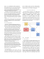
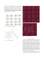
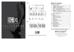
Knight Light LED Chess Set
Nick DeSantis, Alex Haas and Bryan Salicco
Department of Electrical Engineering and
Computer Science, University of Central
Florida, Orlando, Florida, 32816-2450
Abstract — Often times it takes the creativity and
innovation to rehash old ideas to make them more appealing.
Classic games are being overshadowed by new technology
and many times they are forgotten. By adding new features
to an existing game such as chess the idea is to potentially
gain new users and excite existing chess players. Thus, we
decided to use LEDs to light up potential moves to for the
user for each piece designated by infrared optical detectors.
Due to time constraints the chess model designed is modular
allowing the option for additional features to the system.
Index Terms
—
RGB LED, Optical Detector /
Phototransistor, Microcontrollers, polycarbonate.
I. INTRODUCTION
The inspiration for the development of the Knight Light
chess set is mainly to introduce new users to the game of
chess and also excite experienced chess users. The use of
LED lights will teach new users by lighting up potential
moves.
Along with teaching the user the game of chess this
system also encourages interaction with a physical user
rather than playing the game virtually. Many gaming
systems take away the personal experience of playing an
opponent live and in person.
The overall system is a balanced combination of both
software and electrical components with the addition of
the mechanical housing to provide the physical means of
playing chess.
The piece detection system utilizes an optical detector
which sends an infrared light through the polycarbonate
surface to denote whether a piece is present or not. The
optical detector also signals whether to turn the LED
lights on or off while playing the game. It was important
to find a piece of clear material such as Lexan that allows
the transmission of infrared light.
Aside from the aforementioned features one extremely
important characteristic was making the system modular
for future development allowing additional features to be
added given more time and supplementary resources.
II. OVERVIEW
The Knight Light chess set process is fairly simple.
At the start of the game the first user picks up the piece
they would like to move and the system will light up
(either blue or green) indicating the potential moves for
the user. Once the person has placed a piece in one of the
designated lighted squares the lights turn off and the turn
switches to the next user. If a user has the option of taking
an opponent’s piece the lighted square will be red showing
that the opponent’s piece is at risk.
Each time the user makes a move the software is
updated to reflect the current state of the board. The
software keeps track of each piece and each move by
using four one-dimensional arrays (Four arrays – pieces,
colors, LED lights, hardware address).
III. STRUCTURAL DESIGN
The structural components combine both the software
and electrical components to allow the chess player
to physically play the game. It includes the aluminum
housing, the polycarbonate playing surface and the
individual LED compartments.
A. Acrylic Housing
The acrylic housing for the project consists of 5
separately cut pieces to create the desired housing of 13”
x 17” x 2.5”. Refer to Fig. 1 for a 3-D drawing of the
housing.
Fig.1:
Chess Housing Diagram
It was important to be precise when designing this
component because the printed circuit board that was
designed is exactly 12” x 12” which contains the LED
lights and other hardware components that will correspond
to the chess playing surface that will coincidentally is
also 12” x 12”. The additional 5 inches in length will
allow the placement of the vector boards along with the
development board all in the same housing. Each piece
was cut to precise dimensions and then glued on the
corners to create the housing. The acrylic structure is both
light weight and durable for long lasting use.
An addition to the housing we needed a way to open the
box in case there was an issue with the hardware. Due to
the need to make additional adjustments it was important
not to have a permanent structure which could not be
opened once the hardware was placed inside. For this
purpose a hinge along the long side of the box was placed
to allow easy opening of the housing when it needed to be
opened.
For the purpose of allowing power to be connected the
board, a 1” x 1” hole was cut out 1” away from the edge.
This allows the hardware to receive power for proper
functionality.
there are multiple squares each with an LED light there
has to be some sort of protection so the user does not get
confused where to move each piece when playing.
IV. ELECTRICAL HARDWARE
The main hardware components of the Knight Light
LED Chess Set include 64 RGB LEDs, 64 optical detector
/ phototransistors, 16 MCP23017 I/O Exapnders, and an
LPC2148
development
board.
The
LPC2148
communicates with the I/O Expanders via two I2C buses.
I2C refers to a two-wire interface that allows
communication with multiple peripheral devices. The I/O
Expanders then control the LEDs and read input from the
sensors to track the movement of pieces and illuminate
the possible moves a user can make. A block diagram of
the hardware can be seen in Fig. 2.
B. Acrylic Playing Surface
The choice of material for the playing surface was
acrylic due to its natural infrared transmission capabilities,
resistivity to damage over prolonged periods of time and
it is generally much cheaper than other available options.
Clear acrylic allows for the transmission of infrared
light which is important for proper functionality of the
chess board. Since the board utilizes infrared photosensors / optical detectors the main goal was to find a type
of material that allows the transmission of infrared in
order to detect the presence or absence of a chess piece. If
the infrared were refracted always back to the sensor than
the board would not be able to sense whether a piece left
any particular given sensor.
Since the player will be moving chess pieces over the
surface and most likely will not be conscious of whether
they plan on damaging the board. It is important that the
playing surface is not easily scratched by normal use from
the user. One of the goals of designing this chess board is
allowing the board to be used for a long time with
continued use of the playing surface.
Acrylic is also much more affordable than other
materials that transmit infrared light such as Lexan or
other polycarbonate materials. It made obtaining acrylic
an easy choice because when constructing the box thicker
material can be used to make the board sturdy such as
using a thickness of 1/4” much cheaper than 1/8” in other
materials that were originally discussed.
C. LED Compartments
The LED compartments will be suited to protect each
LED light from lighting up the wrong square or having
colors bleed from one square to the next. Essentially since
Fig.2
Block Digram
A. Microcontroller
The LPC2148 provides 512kB of flash memory as well
as 32kB of RAM, an ample amount of memory for
necessary chess algorithms. Two I2C lines provide the
ability to communicate with a larger number of peripheral
devices than the standard GPIO pins would allow, many
other microcontrollers offer only one I2C line. Using the
development board provides a known working subsystem
to go along with the experimental I/O system. The
development board (Fig. 3) plugs directly into a computer
via USB, giving a stable power supply with output pins
that are 3.3v and 5v. The LPC2148 belongs to the ARM7
processor family and can be programmed in C, a language
familiar to all group members. Programming can be done
fairly simply with the user of Flash Magic and an FTDI
board. The LPC2148 provides an ample amount of
features for a reasonable price. Specifications provided in
Table I.
measured reflectance can be seen in Fig. 5.
Fig. 4
Fig. 3
Fairchild QRD1114 Optical Detectors / Photo-Sensors
LPC2148 Development Board
Table I
LPC2148 Microcontroller Specifications
Specs
LPC2148
Flash
512kB
Max. Op Freq
60MHz
CPU
32bit
Programmable
Yes
GPIO
45
I2C Interfaces
2
Power
3.3 - 5.5V
RAM
32 kB
Fig. 5
Schematic of the QRD1114 Optical Detectors / PhotoSensors
C. RGB LED Lights
Common cathode LEDs (Fig. 6) were selected for the
display of possible moves. These LEDs are simple to use
and have a common ground, this allows the individual
colors of each LED to be controlled by a single pin on the
I/O expanders. These LEDs are commonly found in clear
and diffused packages; the clear package was selected to
allow maximum brightness.
B. Sensors
The QRD1114 optical detector/phototransistor (Fig. 4)
works on the basis of emitting an infrared light and
measuring the reflectance of that light. Each board square
will be outfitted with one of these sensors that will be
continuously polled to determine if there is a piece sitting
above it. A simple pull-up resistor is used with the sensor
to allow the I/O expanders to receive a high or low signal
from the sensor based on the amount of reflectance
measured. The emitter can be run on up to 5v, which is
easily obtainable with the LPC2148 development board.
The sensor circuit to obtain a high or low value based on
Fig. 6
Common Cathode Clear RGB LED Lights
D. I/O Expanders
The MCP23017 I/O Expander (Fig. 7) is a 16-bit input/
output expander that can be interfaced with via I2C. The
chip features 3 hardware address pins that allow up to 8
devices to be cascaded on one I2C bus. The operating
voltage ranges from 1.8 to 5.5 volts, meaning the 3.3v or
5v output from the development board will provide
sufficient voltage for the chip. The expander has 16 I/O
pins that are separated into two 8-bit banks. The banks
can easily be addressed and then written to or read from.
When reading from the MCP23017 the 8 bits of the entire
I/O bank access will be returned, this can easily be
accounted for by using a mask to obtain the status of the
pins connected to sensors.
Fig. 7
MCP23017 I/O Expander
From each player’s perspective, the eight-by-eight
game grid is organized into eight rows, called “ranks,”
that run horizontally across the board and eight columns,
called “files,” that run vertically, up and down the board.
The rows and columns are labeled using White’s
perspective of the board. The eight ranks are labeled with
the numbers “1” through “8,” starting at the rank closest
to White and ending with the rank that is farthest from
White. The eight files are labeled with the lowercase
letters “a” through “h,” starting at White’s left and ending
at White’s right.
The eight pawns take up the entire rank that is secondclosest to each player. All the other pieces fill in each
player’s closest rank. Each of the two rooks are positioned
at the left-most and right-most corners of this closest rank,
moving inward and toward the center of the board, the
two knights are placed next to each rook. Next are the two
bishops, one next to each knight. Only the two center tiles
on the closest rank remain open at this point; this is where
the king and queen will be placed. White places its queen
to the left of the king and Black places its queen to the
right of the king. The king and queen are arranged in this
special configuration so that both pieces reside on the
same file (column) as their opponent’s and to prevent
early endgame scenarios. Standard setup can be found in
Fig. 8.
V. SOFTWARE DESIGN
The software that powers the Knight Light LED Chess
Set is a custom-designed, lightweight chess engine. The
software uses several different functions to detect piece
movement on the board, calculate the moves available to
each piece, and look for endgame scenarios.
A. General Chess Gameplay
The classical game of Chess is played with two players
on a square, eight-by-eight, grid of sixty-four alternating
colored squares. Half of the tiles are “light squares,”
usually colored white or beige, and half of the tiles are
“dark squares,” usually colored black or dark brown. The
two players face each other, set the game board between
them, and orient it in a way such that a light square is at
the right-most corner of the board for both players.
Each player starts the game with a matching set of
sixteen pieces and assigned a color, chosen by the two
players, either black or white. During the game, the two
players are referred to by their piece colors, “Black” and
“White.” Each player starts with one king, one queen, two
rooks, two bishops, two knights, and eight pawns.
The objective of the game is to force the opponent’s
king into a “checkmate.”
Fig. 8
Standard Initial Chess Setup
B. Programming
The software will follow a chess game as it is played
out on the chessboard using inputs sent from the
hardware. Sensors on the chessboard will trigger functions
inside the software. The application will process this
information and provide output to the hardware to trigger
the illumination of LEDs, among other things.
The software, designed using the C programming
language, will contain a number of functions that
completely encompass the rules of chess. The software
will be able to determine if a move is valid or not based
on many parameters. The software will keep track of all
chess piece positions on the board at all times during the
game.
C. Special Movement
Standard movement can be found in Fig. 9-14.
However, there are also other moves that need to be
accounted for when playing chess.
1)Pawns
Fig. 13
Standard Bishop Movement
6)Rooks
Fig. 9
Standard Pawn Movement
2)Knights
Fig. 14
Fig. 10
Knight Movement
3)Queens
Fig. 11
Standard Rook Movement
Castling, the first of the three special moves is a
maneuver that involves a player’s king and either of the
same player’s rooks. Castling is a huge offensive and
defensive move; it offers many benefits. It’s the only
move in chess where a player has the opportunity to move
two of their own pieces during the same turn. By castling,
a player’s king moves to one side of the board, away from
its central starting location, while at the same time,
bringing out a rook, once hidden in a corner, into the
center of the board, poised for combat. Refer to Fig. 15
for visual representation of castling.
Queens Movement
4)Kings
Fig. 15
Fig. 12
Standard King Movement
5)Bishops
Castling
Castling can occur only if all of the following
requirements are met:
• The king is not is check.
• The king has not previously moved.
• The selected rook has not previously moved.
• No pieces reside between the king and the
selected rook.
• The king (through this maneuver) does not pass
through a tile under attack.
En passant is the second special move in the game of
chess. “En passant” is French for “in passing.” It is a
special type of pawn capture that a player can perform
immediately after an enemy pawn moves two tiles from
its starting position. Refer to Fig. 16 for visual
representation of en passant.
Fig. 16
En Passant
En passant can occur only if all of the following
requirements are met:
• The attacking pawn must be on the fifth rank.
•
The victim pawn must be on an adjacent file and
move forward two tiles (first movement for this
pawn).
Two arrays are used to run the game’s available move
calculations; one array to store the chess piece types that
are currently spread out on the board and one array to
store the colors of these corresponding pieces. The pieces
are identified by integers: 0 for pawns, 1 for knights, 2 for
bishops, 3 for rooks, 4 for queens, and 5 for kings. 6 is
used to fill the “empty” positions on the board. Colors are
identified similarly using the integer 0 for white and 1 for
black.
A third array is used to store LED illumination
information during each turn. When a piece is lifted off
the board during a move, a software function is triggered
to determine which squares this active piece can move
into. A green light will appear under every non-occupied
square this piece may move into and a red light will
appear under every enemy-occupied square this piece may
move into. The square that this active piece currently
resides will be lit blue. For example, the piece type and
color arrays, integers again, are used to specify values in
this array (0 for no lights, 1 for red, 2 for green, and 3 for
blue).
The fourth and fifth arrays are used to store the physical
hardware address locations of each tile’s photo-sensor and
LED. Once the move determination logic has completed,
these arrays will be looped through in order to pass on
outputs to the hardware. Fig. 17 shows an example LED
movement situation.
After the victim pawn makes it’s first move, the
attacking pawn can move directly behind it, executing the
attack.
Pawn promotion is the third and last special move in
chess. When a pawn traverses the entire board and makes
it to the opponent’s home rank, the pawn must be
promoted into the player’s choice of a queen, knight,
rook, or bishop. Obviously, this move offers incredible
advantages. Experienced chess players will usually resign
once they realize they cannot stop an opponent’s pawn
from becoming promoted.
D. Data Structures
Fig. 17
The chess game can be followed by the software
without the need to explicitly detect each chess piece type
when the pieces are moved. This feat is achieved through
to two factors: (1) Every chess game begins the same
way, with the same piece starting positions, and (2) the
software maintains an array representation of the chess
board.
The chess engine stores five one-dimensional integer
arrays with sixty-four positions. Each array position maps
directly to each of the sixty-four physical squares on the
chessboard.
Example of LED system
VI. SCHEMATICS AND PCB DESIGN
To meet the requirements of a chess board, an 8x8
matrix of sensors and LEDs is used to represent the game
board, with a sensor and LED contained in each square of
the playing surface. Each I/O expander has 16 I/O pins,
allowing each to connect with 4 RGB LEDs and 4
sensors. 16 I/O expanders can be connected to the two
I2C lines, this works out to being able to control 64 LEDs
and 64 sensors, exactly the amount needed for an 8 x 8
chess board. The schematic for the entire system can be
seen in Fig. 18. Following that is the close-up layout of
the schematic in Fig. 19. Fig. 20 shows an overview of the
entire PCB design and Fig 21 shows a close-up of the
same PCB design. All of which needed to be designed
from scratch based of the requirements and specifications
of each of the hardware components.
Fig. 18
Fig. 20
Overview of Entire PCB
Fig. 21
Close-Up of PCB Design
Overview of Entire Schematic
VII. CONCLUSION
Fig. 19
Close-Up of Schematic
The Knight Light LED Chess Board has both complex
software and hardware components all contained inside
of the acrylic housing unit. This project challenged and
stimulated the minds of all of the developers. It was truly
a rewarding journey to have developed this Chess Board
system from scratch using knowledge from both the
classroom and from the numerous hours of research and
dedication of each team member. This system was able to
teach many fundamental and advanced lessons that will
only strengthen each individual for a successful future.
This course has allowed each member to better understand
personal strengths and weaknesses alike when studying
both computer and electrical components.
Chess has been overlooked mainly because of the
advancement of technology in the gaming industry. Upon
the creation of the Knight Light LED Chess Board the
hopes of the system are able to teach and excite both new
and old users with the game of chess. This system also
hopes to encourage more physical gameplay and steer
away from strictly virtual reality which many have come
accustomed to being so familiar. Hopefully more users are
drawn towards the idea of playing chess and give an old
classic the respect it deserves.
All in all this is a system that was designed to not only
teach and excite new and old users but it was designed to
be extremely modular. Designing this system such that
it is modular will allow for the addition of new features
that were not implemented in this prototype. Future
improvements to the system can include the following:
an LCD screen, different player modes such as the use of
an A.I. or open source chess algorithms that are widely
available on the internet to play against, allowing the
user to play both online and physically on the board,
and recording games played to study along with other
possibilities.
Alex Haas – Age: 22
Engineering position at Northrop Grumman following
graduation.
BIOGRAPHIES
Nick DeSantis – Age: 23
A senior at the University of Central Florida, will
receive his bachelor's degree in Computer Engineering
in May of 2013. Nick is interested in development of
desktop applications and web technologies. He will seek
employment as a software engineer in the Orlando area
after graduation.
Bryan Salicco – Age: 24
A senior at the University of Central Florida graduating in
May 2013 with a Bachelor’s of Science in both Computer
Engineering and Electrical Engineering. Bryan plans on
pursuing a career in Software Development as he will be
accepting a position at FedEx Services upon graduation.
ACKNOWLEDGEMENT
The authors wish to acknowledge the assistance and
support of Joshua Mahaz, a software engineer at Lockheed
Martin. He was able to provide general advice with
microcontrollers and circuit design.
REFERENCES
[1]
Keil. (2013). NXP LPC2148 by Phillips
Datasheet and User Manual. [Online]. Available:
http://www.keil.com/dd/chip/3880.html