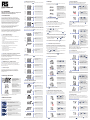
1
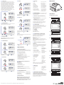
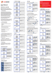
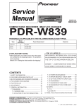
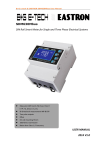
3.1 Voltage and Current
Each successive press of the
button selects a new parameter:
V/A
ESC
4 Set Up
To enter set-up mode, press the E
until the password screen appears.
2015 v1.0
871-8308 MID
Current on each phase.
DIN Rail Smart Energy Meter for Single and
Three Phase Electrical Systems
The unit has a default setting of 3Phase 4wire (3P4).
Use this section to set the type of electrical system.
From the set-up menu, use
MD/
and P
buttons to
PF/HZ
select the system option.
The screen will show the
currently selected power
supply.
Press E to enter the
selection routine. The
current selection will flash.
If an incorrect password
is entered, the display will
show:
1 Introduction
PASS Err
Phase to neutral voltage
THD%.
This document provides operating, maintenance and
installation instructions. This unit measures and displays
the characteristics of single phase two wires (1p2w), three
phase three wires (3p3w,) and three phase four wires (3p4w)
networks. The measuring parameters include voltage (V),
frequency (Hz), current (A), power (kW/Kva/Kvar), Imported,
exported and total Energy (kWh/kvArh). The unit also
measures Maximum demand current and power, this is
measured over preset periods of up to 60 minutes.
This unit is a 1A or 5A current transformer operated and
can be configured to work with a wide range of CTs.
Built-in pulse and RS485 Modbus RTU outputs.
Configuration is password protected.
This unit can be powered from a separate auxiliary (AC or DC)
supply. Alternatively it can be powered from the monitored
supply by linking the voltage reference and neutral reference in
to terminals 5 + 6 (Please refer to wiring diagram).
3.2 Frequency and Power Factor and Demand
Each successive press of the
MD/
PF/HZ
button selects a new range:
Frequency and Power
Factor (total).
Power Factor of each
phase.
• Line frequency
• Currents, current demands and current THD% of all
phases
• Active energy imported and exported
• Reactive energy imported and exported
Maximum Power Demand.
The unit has password protected set-up screens for:
• Changing password
• Supply system selection 1p2w, 3p3w,3p4w
• Demand interval time
Maximum Current
Demand.
• Reset for demand measurements
• Pulse output duration
1. Use the MD/
and P
buttons to scroll through the
PF/HZ
different options of the set up menu.
Each successive press of the
P
button select a new range:
1. The current digit to be set flashes and then can be adjusted
using the MD/
and P
buttons
PF/HZ
2. Press E to confirm each digit setting. The SET indicator
appears after the last digit has been set.
For example, if using a 100/5A current transformer you
will enter 0020, as you need to divide the primary by the
secondary to get the ratio (CT rate).
Please note as this is a MID approved device, you will only
have one opportunity to set the ratio.
4.5.1 CT Reversal
If the CT connections are incorrectly wired, they can be
reversed through the Set System Continued menu:
From the set-up menu,
use MD/
and P
buttons
PF/HZ
to select the “Set Sys
Cont” option. Press E
to enter the sub-menu.
4.2 Change Password
Use the MD/
and P
PF/HZ
to choose the change
password option.
This screen will display,
you can change “Forward”
to “Reverse” on each
individual CT connection.
Press the E to enter the
change password routine.
The new password screen
will appear with the first
digit flashing.
Use MD/
and P
to set
PF/HZ
the first digit and press
E
to confirm your
selection. The next digit
will flash.
Press & Hold E to
confirm your adjustment.
You can then move on to
IB or IC.
4.6 PT
The PT option sets the secondary voltage (PT2 100 to 500V) of
the voltage transformer (PT) that may be connected to the meter.
From the set-up menu, use
MD/
and P
buttons to
PF/HZ
select the PT option. The
screen will show the voltage
PT secondary voltage value.
The default value is 400V.
Repeat the procedure for
the remaining three digits.
3.4 Energy Measurements
E
button selects a new range:
Imported active energy
in kWh.
The interface performs a
self-test and indicates the
result if the test passes.
Exported active energy
in kWh.
Set PT ratios value
Press E to enter the PT
ratio screen.
The range is from 0001
to 9999.
V/A
Press ESC
to exit the number setting routine and return to the
Set-up menu. SET will be removed
4.3 DIT Demand Integration Time
This sets the period in minutes over which the current
and power readings are integrated for maximum demand
measurement. The options are: off, 5, 10,15 30,60 minutes.
Imported reactive energy
in kVArh.
From the set-up menu, use
MD/
and P
buttons
PF/HZ
to select the DIT option.
The screen will show
the currently selected
integration time.
Exported reactive energy
in kVArh.
Press E to enter
the selection routine.
The current time interval
will flash.
Total active energy in kWh.
Use MD/
and P
PF/HZ
buttons to select the time
required.
Total reactive energy in
kVArh.
Press E to confirm the
selection. SET indicator
will appear.
The buttons operate as follows:
Please note the register is 9999999.9 display over two lines.
Secondary PT setting
Press E to enter the
PT secondary voltage
selection routine. The
range is from 100 to 500V.
After setting the last digit,
SET will show.
*After a short delay, the screen will display active
energy measurements.
E
Set CT Ratio value
Press E to enter the
CT Ratio setting screen.
The range is from 0001
to 9999.
repeatedly until
Total kW, kVArh, kVA.
The second screen
indicates the firmware
installed in the unit and
its build number.
Select the Energy display screens.
In Set-up mode, this is the “Enter” or
“Right” button.
V/A
ESC
When Setting up the unit, some screens require the entering
of a number. In particular, on entry to the setting up section, a
password must be entered. Digits are set individually, from left
to right. The procedure is as follows:
Instantaneous Volt-Amps
in KVA.
Each successive press of the
Select the Power display screens.
In Set-up Mode, this is the
“Down” button.
Secondary CT setting
Press E to enter the
CT secondary current
selection routine.:5A/1A
4.1.2 Number Entry Procedure
Instantaneous Reactive
Power in kVAr.
2 Start Up Screens
P
E
5. Having completed a parameter setting, press ESC to return
to a higher menu level. The SET indicator will be removed
and you will be able to use the MD/
and P
buttons for
PF/HZ
further menu selection.
Instantaneous Active
Power in kW.
Two pulsed outputs that can be set for active(kWh) or
reactive (kVArh) energy. Terminals 11 & 12 have a fixed
output of 3200imp/kWh. The settable pulse output is
terminals 9 & 10.
Select the Frequency and Power factor
display screens. In Set-up Mode, this is
the “Up” button.
and
4. Having selected an option from the current layer, press
to confirm your selection. The SET indicator will appear.
1.4 Pulse output
MD/
PF/HZ
MD/
PF/HZ
3. After setting the last digit, press ESC to exit the number
setting routine. The SET indicator will be removed.
3.3 Power
RS485 serial port with Modbus RTU protocol to provide a
means of remotely monitoring and controlling the Unit.
Set-up screens are provided for setting up the RS485 port.
Refers to section 4.8.
ESC
From the set-up menu,
use MD/
and P
buttons
PF/HZ
to select the CT option.
to confirm your selection
3. If an item flashes, then it can be adjusted by the
P
buttons.
1.3 RS485 Serial – Modbus RTU
Selects the Voltage and Current display
screens. In Set-up Mode, this is the
“Left” or “Back” button.
E
V/A
Please also be aware on the MID version you can only
program the ratio once.
3 Measurements
4.5 CT
The CT option sets the secondary current (CT2 1A or 5A) of
the current transformer (CT) that wires to the meter.
4.1.1 Menu Option Selection
6. On completion of all setting-up, press
the measurement screen is restored.
• Power, maximum power demand and power factor
The first screen lights
up all display segments
and can be used as a
display check.
Press & hold E to confirm your adjustment, you can then
V/A
move to the next parameter setting or press & hold ESC
to
exit the set-up menu.
V/A
• Line voltage and THD% (total harmonic distortion) of
all phases
This unit has to be configured to operate with a CT,
The optional secondary currents or 1A or 5A. it is programmed
by inputting the ratio (Please see section 4.5).It can be used
on primary currents up to 6000A.
Use MD/
and P
PF/HZ
buttons to select the
required system option:
1P2(W),3P3(W) ,3P4(W).
repeatedly until the
Some menu items, such as password and CT, require a
four-digit number entry while others, such as supply system,
require selection from a number of menu options.
2. Press
The Unit can measure and display:
1.2 Current Transformer Primary Current
V/A
To exit setting-up mode, press ESC
measurement screen is restored.
4.1 Set-up Entry Methods
Current THD% for each
phase.
1.1 Unit Characteristics
V/A
button for 3 seconds,
Setting up is passwordprotected so you must
enter the correct password
(default ‘1000’) before
processing.
Phase to neutral voltages.
User Manual
4.4 Supply System
Press
V/A
ESC
to exit the DIT selection routine and return to the menu.
For example, if set the ratio to be 100,it means the primary
voltage equals secondary voltage x100.
4.7 Pulse Output
This option allows you to configure the pulse output. The
output can be set to provide a pulse for a defined amount of
energy active or reactive. Use this section to set up the relay
pulse output—Units: kWh, kVArh
From the set-up menu, use
MD/
and P
buttons
PF/HZ
to select the Pulse output
option.
Press E to enter the
selection routine. The unit
symbol will flash.
Use MD/
and P
PF/HZ
buttons to choose kWh or
kVArh.
On completion of the entry procedure, press E to confirm
V/A
the setting and press ESC
to return to the main set up menu.
4.7.1 Pulse rate
4.8.3 Parity
6 Dimensions
5.3 Accuracy
You can configure the pulse output to relate to a defined
amount of imported or exported energy. This can also be set
to use with active energy (kWh) or reactive energy (kVarh).
From the set-up menu, use
MD/
and P buttons to
PF/HZ
select the parity option.
Please note there are limitations that need to be factored in
when setting the pulsed output. This is based upon the relay
output only being able to pulse 2 times in one second.
For example, If the CT is set to 500/5A on a single phase
network this would generate (500Ax230V=115,000 / 1000)
115kWh which is 31W per second. A setting of 10imp/kWh
(10 pulses per kWH) would generate 3 pulses per second.
This will exceed the 2 pulse per second limitation.
Press E to enter the
selection routine. The
current setting will flash.
Pulse settings: 1 pulse per 0.01(10W) / 0.1(100W) / 1 (1kWh) /
10(10kWh) / 100(100kWh) /1000 (1000kWh)
Use
and P buttons
to choose parity (EVEN /
ODD / NONE (default)).
• Voltage
0·5% of range maximum
• Current
0·5% of nominal
• Frequency
0·2% of mid-frequency
• Power factor
1% of unity (0.01)
• Active power (W)
±1% of range maximum
• Reactive power (VAr)
±1% of range maximum
• Apparent power (VA)
±1% of range maximum
• Active energy (Wh)
Class 1 IEC 62053-21
• Reactive energy (VARh)
±1% of range maximum
• Total harmonic distortion
1% up to 31st harmonic
• Response time to step input
1s, typical, to >99% of
final reading, at 50 Hz.
MD/
PF/HZ
From the set-up menu,
use MD/
and P
buttons
PF/HZ
to select the Pulse Rate
option.
On completion of the entry procedure, press E to
V/A
confirm the setting and press ESC
to return to the main
set up menu.
Press E to enter the
selection routine. The
current setting will flash.
0.01/0.1/1/10/100kWh/
kVArh per pulse.
4.8.4 Stop bits
5.4 Auxiliary Supply
Two-way fixed connector with 2·5mm2 stranded wire capacity.
85 to 275V a.c. 50/60Hz ±10% or 120V to 380V d.c. ±20%.
Consumption <2W 10VA.
5.5 Interfaces for External Monitoring
Three interfaces are provided:
• RS485 communication channel that can be programmed
for Modbus RTU protocol
The energy monitored can be active or reactive and the pulse
width can be selected as 200, 100 or 60ms.
Press E to enter the
selection routine. The
current setting will flash.
From the set-up menu,
use MD/
and P
buttons
PF/HZ
to select the Pulse width
option.
Use MD/
and P
PF/HZ
buttons to choose stop
bit (2 or 1)
On completion of the entry procedure, press E to
V/A
confirm the setting and press ESC
to return to the main
set up menu.
Press E to enter the
selection routine. The
current setting will flash.
Use MD/
and P
buttons to choose pulse width.
PF/HZ
On completion of the entry procedure press E to confirm
V/A
the setting and press ESC
to return to the main set up menu.
1
• Pulse output 3200imp/kWh (not configurable)
Rate can be set to generate 1 pulse per:
0.01 = 10 Wh/VArh
0.1 = 100 Wh/VArh
1 = 1 kWh/kVArh
10 = 10 kWh/kVArh
100 = 100 kWh/kVArh
From the set-up menu,
MD/
and P
buttons to
PF/HZ
select the address ID.
Press E to confirm the setting and press
the main set up menu.
V/A
ESC
to return to
5 Specifications
Press E button to enter
the selection routine. The
current setting will be
flashing.
Single Phase,2 Wires
Use
and P
buttons to choose Modbus
address (001 to 247).
MD/
PF/HZ
• Voltages between phases 173 to 500V a.c.
Single Phase,2 Wires
(3p supplies only).
From the set-up menu,
use MD/
and P
buttons
PF/HZ
to select the Baud Rate
option.
• Percentage total voltage harmonic distortion (THD%) for
P2
P1
L1
each phase to N ( not for S2
3p3wS1supplies).
• Percentage voltage THD% between L2
phases
(three phase supplies only).
1
2THD%
B A for each phase
• Current
Current inputs
5.1.2S0Power factor
and Frequency and
9 10 11
12 13 14 15 16 17 18 19 20
Max.
Demand
• Frequency in Hz
• Power 0 to 3600 MW
• Volt-amps 0 to 3600 MVA
• Maximum demanded power since last Demand reset
Power factor
• Maximum neutral demand current, since the last Demand
reset (for three phase supplies only)
On completion of the entry procedure, press
to confirm
V/A
the setting and press ESC
to return to the main set up menu.1A FAST
E
2
3
4
5
6
7
8
Voltage inputs
L
N
N
5.1.3
Energy LMeasurements
1A FAST
BLOW
FUSE
0 to
9999999.9 kWh
BLOW FUSE• Imported/Exported active energy
AUX
L1 • Imported/Exported reactive energy
N
4
5
6
7
8
L
N
L
N
L1
L2
1A FAST
BLOW FUSE
AUX
N
3 Phase,3
7.2 Three phase
three Wires
wires
P2
S2
LOAD
RS485 network
address
1
2 B A nnn – 3-digit number, 1 to 247
P2
S2
2 B A
1
Modbus™ Word order Hi/Lo byte order is set automatically to
normal or reverse. It cannot be configured from the
RS485
Current inputs
S0
set-up menu.
P1
S1
RS485
S0
9 10 11 12 13 14 15 16 17 18 19 20
P1
S1
L1
L2
L3
Current inputs
9 10 11 12 13 14 15 16 17 18 19 20
5.6 Reference Conditions of Influence
Quantities
Influence Quantities are variables that affect measurement
errors to a minor degree. Accuracy is verified under nominal
value (within the specified tolerance) of these conditions.
• Ambient temperature
23°C ±1°C
• Input waveform
50 or 60Hz ±2%
Sinusoidal (distortion
factor < 0·005)
5
6
7
8
• Auxiliary Voltage
supplyinputs
voltage L
N
L
N
2
3
4
• Auxiliary supply frequency
Nominal ±1%
1A FAST
BLOW FUSE
Sinusoidal
(distortion
1A FAST
• Auxiliary
BLOW
FUSE supply waveform (if AC)
AUX
factor < 0·05)
Terrestrial flux
5.7 Environment
Phase,3 Wires
• Operating3 temperature
• Storage temperature
LOAD
• Altitude
1
• Vibration
P2
S2
2 B A
RS485
S0
-25°C to +55°C*
2
3
4
Voltage inputs
5
6
7
8
L
N
L
N
1A FAST
BLOW FUSE
P1
S1
0 to
L1
L2
L3
3 Phase,4
Wires
7.3 Three phase
four wires
L1
95%,
L2
non-condensing
Up toL3
3000m
P1
S1
P2
S2
P1
S1
LOAD
P2
S2
2 B A
1
1 minute
Current inputs
1A FAST
BLOW FUSE
AUX
-40°C to +70°C*
P2
S2
• Relative humidity
1
Nominal ±1%
10Hz to 50Hz, IEC
60068-2-6, 2g
RS485
S0
• Shock9 10 11 12 13 14 15 16 17 18 19 2030g in 3 planes
P2
S2
P1
S1
P1
S1
L1
L2
L3
Current inputs
9 10 11 12 13 14 15 16 17 18 19 20
5.8 Mechanics
• Reactive power 0 to 3600 MVAr
1
3
*Maximum operating and storage temperatures are in the
context of typical daily and seasonal variation.
• Instantaneous power:
Use MD/
and P
PF/HZ
buttons to choose Baud
rate 2.4k. 4.8k, 9.6k,
19.2k, 38.4k
Stop bits 1 or 2
• Warm up time
RS485
Press E to enter the
selection routine. The
current setting will flash.
P1
S1
• Magnetic
field of external origin
N
• Phase to neutral voltages 100 to 289V a.c.
(not for 3p3w supplies).
LOAD
P2
S2
L1
5.1.1 Voltage and Current
On completion of the entry procedure, press E button to
V/A
confirm the setting and press ESC
button to return the main
set-up menu.
Parity none (default) / odd / even
LOAD
1
The unit can monitor and display the following parameters of a
single phase two wire (1p2w), three phase three wire (3p3w) or
three phase four wire (3p4w) system.
2
L1
• Input waveform
5.1 Measured Parameters
Current inputs
1A FAST
BLOW FUSE
Pulse width 200/100/60 ms.
Baud rate 2400, 4800, 9600, 19200, 38400
Press E to enter the
selection routine. The dIt
will flash.
RS485
S0
Voltage inputs
For Modbus RTU, the following RS485 communication
parameters can be configured from the set-up menu:
4.8.1 RS485 Address
2 B A
9 10 11 12 13 14 15 16 17 18 19 20
1
The meter provides a function to reset the maximum demand
value of current and power.
There is a RS485 port can be used for communication using
Modbus RTU protocol. For Modbus RTU, parameters are
selected from Front panel.
L1
L2
Opto-coupler with potential free SPST-NO Contact
(Contact range 5-27VDC / Max current input: Imin 2mA and
Imax 27mA DC). The pulse output can be set to generate
pulses to represent kWh or kVArh.
5.5.2 RS485 Output for Modbus RTU
From the set-up menu, use
MD/
and P
buttons to
PF/HZ
select the reset option.
P1
S1
5.5.1 Pulse Output
4.9 CLR
4.8 Communication
P2
S2
LOAD
The Modbus configuration (baud rate etc.) and the pulse
relay output assignments (kW/kVArh, import/export etc.)
are configured through the set-up screens.
4.7.2 Pulse Duration
4.8.2 Baud Rate
7.1 Single Single
phasePhase,2
two wires
Wires
• Relay output indicating real-time measured energy.
(configurable)
From the set-up menu, use
MD/
and P
buttons to
PF/HZ
select the stop bit option.
Use MD/
and P
buttons to choose pulse rate. On
PF/HZ
completion of the entry procedure, press E to confirm the
V/A
setting and press ESC to return to the main set up menu.
7 Installation
0 to 9999999.9 kVArh
• Total active energy
0 to 9999999.9 kWh
• Total reactive energy
0 to 9999999.9 kVArh
5.2 Measured Inputs
Voltage inputs through 4-way fixed connector with 2.5mm²
stranded wire capacity. Single phase two wire(1p2w), three
phase three wire(3p3w) or three phase four wire(3p4w)
unbalanced. Line frequency measured from L1 voltage
or L3 voltage. Three current inputs (six physical terminals) with
2.5mm² stranded wire capacity for connection of external CTs.
Nominal rated input current 5A or 1A a.c. Rms.
RS Components LTD | www.rs-components.com | Specifications are subject to change without notice
• DIN rail dimensions
72 x 94.5 mm (WxH)
per DIN 43880
• Mounting
DIN rail (DIN 43880)
• Sealing
1 2
• Material
3
4
Voltage inputs
1A FAST
BLOW 5.9
FUSEDeclaration
L1
IP51 indoor
5
6
7
8 Self-extinguishing UL
L
N
L
N
1
94 V-0
1A FAST
BLOW FUSE
ofAUX
Conformity
We, RS Components LTD, declare under our sole
L2
responsibility
as the manufacturer that the poly phase
multifunction
electrical energy meter “871-8308” correspond
L3
to the production model described in the EC-type examination
certificate and to the requirements of the Directive 2004/22/
EC EC type examination certificate number 0120/SGS0150.
Identifcation number of the NB 0120.
2
3
Voltage inputs
1A FAST
BLOW FUSE
L1
L2
L3
N
4
5
6
7
8
L
N
L
N
AUX
1A FAST
BLOW FUSE