1
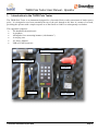
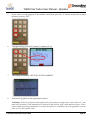
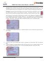
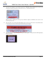
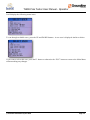
THOR Pole Tester User Manual - Operator Version 2.0 Final: July 2015 – THOR Pole Tester User Manual - Operator THOR Pole Tester User Manual - Operator Table of Contents 1. Introduction to the THOR Pole Tester ............................................................. 3 2. Principle of the THOR Pole Tester ................................................................... 4 3. Setting Up ........................................................................................................... 5 3.1 3.2 User Data ....................................................................................................................... 5 Connecting Components ............................................................................................... 5 4. Application ......................................................................................................... 6 5. Testing Procedure ............................................................................................. 7 © PortaCAT Industries Pty Ltd 2015 Page 2 THOR Pole Tester User Manual - Operator 1. Introduction to the THOR Pole Tester The THOR Pole Tester is an instrument designed for a fast and effective safety assessment of timber power poles. It is designed to test from essentially the top of the pole through to the base in a matter of seconds, providing the operator with a simple response as to the fitness to climb or to subsequently test further. The equipment comprises: The handheld electronics unit A geophone An impulse force measuring hammer (“the hammer”) A carrying case AC Power Adaptor USB to LEMO connector Handheld Electronics Unit Impulse Force Hammer Geophone Data Cable © PortaCAT Industries Pty Ltd 2015 Power Adaptor Page 3 THOR Pole Tester User Manual - Operator 2. Principle of the THOR Pole Tester The instrument detects, analyses and records the signal of a series of stress waves entered into the pole by the hammer. On board processors analyse the signal based on the duration of the wave form against the impulse force and provides the operator with a visual clue as to the state of the pole. When the force is applied to the pole from the impulse hammer, the stress wave travels up to near the top of the pole and down to near the base. The location of the test is important so that the waveform for the signal results in the most effective analysis. In presenting this response the THOR Pole Tester doesn’t provide the end user with an engineering analysis of the pole, but a general indication of the pole condition. An important feature of the THOR Pole Tester is that the recorded wave form is able to be re-assessed as algorithms and analysis tools improve. Where the expected duration of the wave signal relative to the force is within a particular range, the THOR unit provides the operator with a ‘traffic light’ signal response of either green, amber or red. The on-board analytics will be improved as more pole information is recorded and analysed. © PortaCAT Industries Pty Ltd 2015 Page 4 THOR Pole Tester User Manual - Operator 3. Setting Up There are several items that need to be completed before an operator is able to progress to using the THOR Pole Tester in the field. Once set up there is limited requirement to maintain these files. Do not delete any of the system .CSV files as all are critical to the operation. It pays to charge the unit prior to their operation and a power adaptor is provided for this purpose. It generally takes an hour or so to fully charge and the unit will advise when charging is complete. With an efficient power management system on board, a fully charged THOR unit will operate for at least a couple of days. Power Supply Socket 3.1 User Data User data in a comma separated value (CSV) format is able to be updated by Groundline Engineering with specific information or generic parameters e.g. UTILITY01. Otherwise a person can revise the User.csv file themselves but they must keep the same format. Any variation to the file will corrupt the operation of the THOR unit. 3.2 Connecting Components First make sure that the rubber end of the hammer is attached firmly. Continue to tighten every 4 or 5 poles to make sure the energy transfers properly through the bolt. The components provided with the THOR Pole Tester are straightforward, with the cables from the geophone and the hammer fastened into the base of the unit into the respective colour coded adapters. These are not interchangeable between the hammer and geophone and no forcing is required. There is no particular order required when connecting the components. Connect the BNC connector end of the cable to the base of the hammer. © PortaCAT Industries Pty Ltd 2015 Page 5 THOR Pole Tester User Manual - Operator Note the raised bumps at the end of each connector. These are specific to each socket and grooves are located that match the pattern of the connector. The cables are also colour coded to the sockets (yellow for Hammer and red for Geophone). There is a red dot on both the socket and the connector to line up the grooves to the raised bumps. 4. Application The general rules of applying the THOR Pole Tester are to: Place the geophone on one side of the pole within 100mm of ground level where possible. For reinforced poles, the effective ground line is at the top of the steel. Choose an area of the pole that is solid and has no sapwood separation. In general the hammer is used on the opposite side of the pole to the geophone. If unable to reach around then go as far as possible so that the hammer blow is not affected by the shortness of the cable. It is not important what orientation you use the geophone and hammer around the pole although inline is preferred. When swinging the hammer only go back about 30-40cm and swing at the pole with only moderate force. Generally the force applied to swing the hammer should be roughly enough to bounce back the hammer to the original position with a loose hand. Any force applied that is too hard or too soft will result in flawed result (Hammer value indicates too soft or too hard). Make sure the geophone is held tightly and firmly in position against the timber – pointing to the centre of the pole - whilst swinging the hammer. Keep the geophone and hammer strike at the same level when testing the pole. If you are unable to test on either side of the pole then place the geophone in the appropriate location and use the hammer as close to 180o as you can. © PortaCAT Industries Pty Ltd 2015 Page 6 THOR Pole Tester User Manual - Operator 5. Testing Procedure For routine testing follow below operating procedure: 1. Connect the components and turn on the THOR Pole Tester by pressing the power button. 2. The firmware loads and the introductory information displays. Press any key on the keypad to progress to the Main Menu. 3. The current user and the menu options available are displayed. Note the serial number for the Hammer and the Geophone – these should match the items that come with the kit. 4. Wait until the GPS position is determined. © PortaCAT Industries Pty Ltd 2015 Page 7 THOR Pole Tester User Manual - Operator 5. If you want to see the progress of the satellite connections, press the “A” button and go back to main menu by pressing “ESC” 6. To begin testing, press the F1 button (Continue to Test). 7. The reading will display “HIT POLE WITH HAMMER”. 8. Position the geophone in the appropriate location. Technique: Place the geophone firmly against the pole pointing straight to the centre and level. Also make sure the timber is not laminated as it needs to be placed on a good, clean and firm surface. Place about 100mm from the ground and if on a slope then place in a situation where the geophone is on the same level as the hammer strike. © PortaCAT Industries Pty Ltd 2015 Page 8 THOR Pole Tester User Manual - Operator 9. Swing the hammer against the pole Note that you don’t have to hit the pole hard, but firmly. You will immediately come up with a result and each result will display along the top left of the screen. The vertical bar that has the green area displayed is the amount of energy recorded by the hammer blow. Technique: Swing from about 300-400mm out from the pole so that the round rubber end of the hammer hits the surface as perpendicular as possible. The display will show you how hard you have hit and use this to gauge whether you need to go softer or harder on the swing. Each of the three vertical squares will display green, amber or red for Hammer (H), Dynamic Stiffness (S) and Mobility (M) from the top down respectively. If the hammer blow is insufficient then the words “Soft Hit. Striker Harder” will display. You have 4 attempts for each of the 4 recorded readings to obtain a valid result. If the hammer blow is insufficient, hit the ‘ESC’ key and start again. 10. A result that can be analysed will show as “Valid Test Result” and you will then be progressed to the next reading. 11. If you have either a poor hammer strike result or a geophone error, then hit the ‘ESC’ key and start again. Continue through the remaining hammer strikes and each will give you an output summary for the reading with additional graphs for Force, Velocity and Mobility that show each of the results. 12. © PortaCAT Industries Pty Ltd 2015 Page 9 THOR Pole Tester User Manual - Operator 13. Once the four readings are successfully returned the THOR Pole Tester will advise the overall result and indicate whether anomalies are detected or not e.g. “FLAWS DETECTED” N.B.: If 3 of the 4 readings are each all green for Hammer, Stiffness and Mobility then treat the result as No Flaws Detected. 14. Press the ‘ESC’ key to return to the Main Menu or the ‘F2’ key to save the result. You can then choose to retest the pole or move to the next pole and start the process again. 15. Once the testing is completed then press the power button again. It will present the following display then power down. © PortaCAT Industries Pty Ltd 2015 Page 10 THOR Pole Tester User Manual - Operator 6. User Setup on Device There are several items that need to be completed before an operator is able to progress to using the THOR Pole Tester in the field. Once set up there is limited requirement to maintain these files. Do not delete any of the system .CSV files as all are critical to the operation. 16. When the start-up screen and the introductory information displays press any key on the keypad to progress to the Main Menu. 6.1 Changing User When the THOR Pole Tester is first loaded, on the Main Menu screen it shows the current user selected. To change the user, press the F2 button to Edit the Sample Config(uration). © PortaCAT Industries Pty Ltd 2015 Page 11 THOR Pole Tester User Manual - Operator It will display the following menu items. To run through available users, press the UP and DOWN buttons. A new user is displayed similar to below. If you want to select this user, press the F1 button or otherwise the “ESC” button to return to the Main Menu without making any changes. © PortaCAT Industries Pty Ltd 2015 Page 12