1
Online Building Plan Sanction User Manual – Building Plan - Fresh Residential Plotted Development
Architect
MCD
Municipal Corporation of Delhi
Online Building Plan Sanction
User Manual
To
Prepare Building Plan
For
Fresh Residential Plotted Development
Version 1.02
Confidential to MCD
Page 1 of 80
Online Building Plan Sanction User Manual - Building Plan - Fresh Residential Plotted Development
Architect
MCD
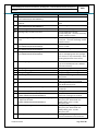
Table of Contents
1.
INTRODUCTION
3
2.
INTENDED AUDIENCE
3
3.
REFERENCES
3
4.
DEFINITIONS AND ACRONYMS
3
5.
PREREQUISITE
4
6.
BUILDING PLAN CREATION
5
6.1
ENVIRONMENT PREPARATION
6.2
GENERAL GUIDELINE
6.2.1 Convert existing DWG building plan
6.2.2 Create a new DWG building plan
6.2.3 Site Plan
6.2.4 Plan
6.2.5 Section
6.2.6 Elevation
6.2.7 Paper Size
6.2.8 Complete
6.2.9 Mandate Features
6.2.10
Drawing Curved features
6.2.11
Key plan/ Layout plan / Part Layout Plan
6.2.12
Name plate / Certificates / Area chart / Parking chart
6.2.13
Others
6.3
DRAW BUILDING PLAN USING MENU
6.3.1 Site Plan
6.3.2 Floor Area (Plan)
6.3.3 Dwelling Features (Plan)
6.3.4 Room (Plan)
6.3.5 Servant Quarters (Plan)
6.3.6 Building Features (Plan)
6.3.7 Floor Height (Section)
6.3.8 Parking (Plan)
6.3.9 Layout (Plan)
6.3.10
Miscellaneous
6.3.11
Others
6.3.12
Paper
6.3.13
Complete
6.4
DOS
6.5
DON’T
5
17
21
23
36
37
37
38
39
39
39
40
44
44
44
45
46
49
51
55
56
57
61
63
64
65
66
67
69
70
70
7.
FREQUENT MISTAKES TO BE AVOIDED
71
8.
GUIDELINE TO CORRECT THE VALIDATION ERROR
72
9.
FEEDBACK / HELP LINE
80
Confidential to MCD
Page 2 of 80
Online Building Plan Sanction User Manual - Building Plan - Fresh Residential Plotted Development
Architect
1.
MCD
Introduction
This document provides guidelines and instruction to the public who wish to avail Online Building Plan
Sanction Service for Fresh Residential Plotted Development.
Building Plan in *.DWG format to be prepared and uploaded for the Bye-law validation and get it
sanctioned by MCD
Before preparing please download the latest version of the User Manual, *.mun, *.vlx etc
2.
Intended Audience
3.
Architects
Engineers
Supervisors
Draughtsman
MCD Building Plan Sanction Authority
References
S. No
1
2
4.
References
Building Bye-Law 1983
Master Plan of Delhi 2021
Definitions and Acronyms
Abbreviation/Term
MCD
BBL
BP ID
MPD
NA
Min.
Max.
M
Description
Municipal Corporation of Delhi
Building Bye-Law 1983
Build Plan ID – System generated ID while applying for Building Plan Sanction
Master Plan of Delhi 2021
Not Applicable
Minimum
Maximum
Meters
OBPS
Online Building Plan Sanction
sq. m
Square Meter
Confidential to MCD
Page 3 of 80
Online Building Plan Sanction User Manual - Building Plan - Fresh Residential Plotted Development
MCD
Architect
NR
No restriction
FAR
Floor Area Ratio = Total covered area of all the floor x 100 / Plot Area
DU
Dwelling unit
ECS
Equivalent Car Space
5.
Prerequisite
Registration with MCD
Knowledge in BBL and MPD
Building Plan / Architectural Drawing Creation experience
AutoCAD experience
Confidential to MCD
Page 4 of 80
Online Building Plan Sanction User Manual - Building Plan - Fresh Residential Plotted Development
Architect
6.
MCD
Building Plan Creation
6.1 Environment Preparation
Step 1: Download latest version of the following files from the portal and save them to a local folder.
1. MCD-Fresh_Res_Plotted_V1.0.mnu
2. MCD-Fresh_Res_Plotted_V1.0.vlx
Confidential to MCD
Page 5 of 80
Online Building Plan Sanction User Manual - Building Plan - Fresh Residential Plotted Development
Architect
MCD
Version V1.0 is given for example. Always before startup download the latest *.mnu & *.vlx
files from the portal; may have different latest version number.
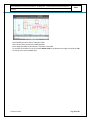
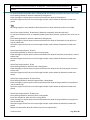
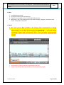
Step 2: Start AutoCAD (AutoCAD 2004 to 2012 can be used to create the building plan)
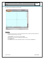
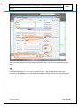
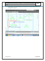
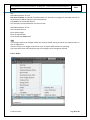
While opening new drawing in AutoCAD, make sure acad.dwt is selected from template as shown in the
below figure. Do not use any other template like acadiso.dwt, am_ansi.dwt etc …
Confidential to MCD
Page 6 of 80
Online Building Plan Sanction User Manual - Building Plan - Fresh Residential Plotted Development
Architect
MCD
Fig: Before loading *.mun
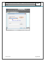
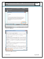
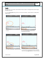
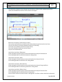
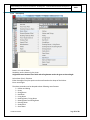
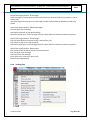
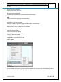
Step 3: Type Menuload in the AutoCAD command line and press Enter key
Press Browse button in ‘Load/Unload Customization’ dialog box
Confidential to MCD
Page 7 of 80
Online Building Plan Sanction User Manual - Building Plan - Fresh Residential Plotted Development
MCD
Architect
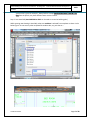
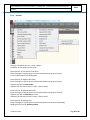
In ‘Files of Type’ chose *.mun and select the respective *.mnu file and press ‘Open’ button.
Press Load button in ‘Load/Unload Customization’ dialog box. Then press Close button.
Confidential to MCD
Page 8 of 80
Online Building Plan Sanction User Manual - Building Plan - Fresh Residential Plotted Development
Architect
MCD
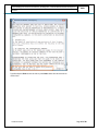
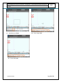
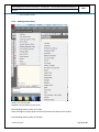
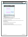
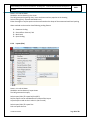
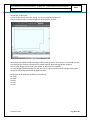
Upon successfully loaded a new MCD-Fresh_Res_Plotted menu will be displayed on the top.
TIPS:
In case if you get ‘Menu already loaded’ message means the same version is already loaded
hence need not load again. Just check whether you need to click on Show Menu Bar as shown
below.
Show menu bar
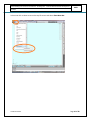
In few AutoCAD version even after loading the *mnu file, the menu may not be visible as shown below.
Confidential to MCD
Page 9 of 80
Online Building Plan Sanction User Manual - Building Plan - Fresh Residential Plotted Development
Architect
MCD
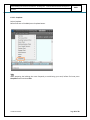
In that case click on down arrow on the top left corner and select Show Menu Bar.
Confidential to MCD
Page 10 of 80
Online Building Plan Sanction User Manual - Building Plan - Fresh Residential Plotted Development
MCD
Architect
Now MCD-Fresh_Res_Plotted menu will be visible.
Unload Menu
If you get a latest version of *.mun from the MCD portal, then unload the already loaded menu
as follows and load the latest *.mnu again.
Type Menuload in the command line and press Enter
Select the old *.mnu from the ‘Loaded Customization Groups’
Press Unload button
Press Browse button and select the folder and latest *.mnu file and press Load button.
Confidential to MCD
Page 11 of 80
Online Building Plan Sanction User Manual - Building Plan - Fresh Residential Plotted Development
Architect
Confidential to MCD
MCD
Page 12 of 80
Online Building Plan Sanction User Manual - Building Plan - Fresh Residential Plotted Development
Architect
MCD
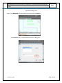
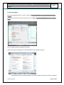
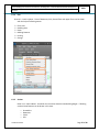
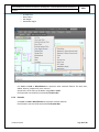
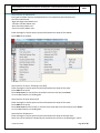
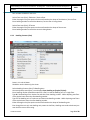
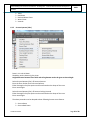
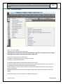
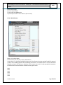
Step 4: Type Appload in the AutoCAD command line and press Enter
‘Load/Unload Application’ dialog box will open, if required in ‘Files of Type’ chose *.vlx. Navigate
to the folder and select respective *.vlx then press Load button. Successfully loaded message
can be seen as shown in the below image. Then press Close button. Remember to load the
*.vlx during each time of opening a *.DWG.
Confidential to MCD
Page 13 of 80
Online Building Plan Sanction User Manual - Building Plan - Fresh Residential Plotted Development
Architect
MCD
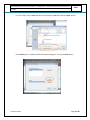
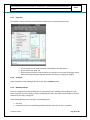
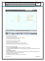
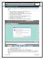
Upon successful loading of the latest *.VLX, accept the disclaimer and the license agreement as shown
below.
TIPS:
Each time opening the DWG *.VLX need to be loaded
In case downloaded latest *.VLX, can be re-loaded the latest *.VLX by following the above setps.
Instead of typing Appload you can type AP and press Enter to navigate to the Load / Unload dialog box.
Confidential to MCD
Page 14 of 80
Online Building Plan Sanction User Manual - Building Plan - Fresh Residential Plotted Development
Architect
MCD
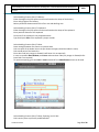
Read and Press OK button
Read and press Enter to continue
Confidential to MCD
Page 15 of 80
Online Building Plan Sanction User Manual - Building Plan - Fresh Residential Plotted Development
Architect
MCD
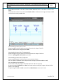
Type Y and press Enter to use the VLX or press Enter those who do not want to
use the VLX
Confidential to MCD
Page 16 of 80
Online Building Plan Sanction User Manual - Building Plan - Fresh Residential Plotted Development
Architect
MCD
6.2 General Guideline
Even upon loading the latest *.mnu & *.vlx files, all existing AutoCAD menus and commands will work
as usual.
The tool will take care of units; the auto set units is in Meter. Draw the building features in 1:1 scale in
Meter.
Do not change the above Drawing unit settings.
The tool will set the saving option to AutoCAD 2000. Do not change this option.
No separate wall layer is being maintained. Distance between two features shall be calculated
Confidential to MCD
Page 17 of 80
Online Building Plan Sanction User Manual - Building Plan - Fresh Residential Plotted Development
Architect
MCD
as wall thickness. Hence before staring the next feature mark the required wall thickness and
then begin from that point.
Confidential to MCD
Page 18 of 80
Online Building Plan Sanction User Manual - Building Plan - Fresh Residential Plotted Development
Architect
MCD
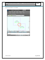
Overlap of two features is not allowed.
Confidential to MCD
Page 19 of 80
Online Building Plan Sanction User Manual - Building Plan - Fresh Residential Plotted Development
Architect
MCD
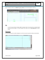
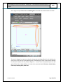
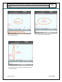
Outer edge overlap of Floor Area and Dwelling Area is allowed and should be drawn as below.
The tool is designed to represent a big plot having many buildings (blocks), each building has
many floors, each floor has many dwelling area, each dwelling has many rooms and the building
has common features like Lift, Shaft, Pergola etc … Hence even the proposed plot has only
ground floor with a single dwelling unit need to be represented with Plot Area, Covered Area,
Floor Area, Dwelling Area, Rooms etc.
Confidential to MCD
Page 20 of 80
Online Building Plan Sanction User Manual - Building Plan - Fresh Residential Plotted Development
Architect
6.2.1
MCD
Convert existing DWG building plan
Open
Open existing DWG in AutoCAD
Scale
Scale entire objects to 1:1 meter using following scale factor.
S. No.
1.
2.
3.
4.
Units of existing DWG
Architectural (Feet / Inches)
Millimeters
Meters
Other units
Scale factor
0.025403
0.001
NR
Calculate and apply
Remarks
TIPS:
Usually Site Plans are created in different scales. Accordingly scale the Site Plan to make to 1:1 in Meter
Confidential to MCD
Page 21 of 80
Online Building Plan Sanction User Manual - Building Plan - Fresh Residential Plotted Development
Architect
MCD
After scaling measure few features using Dist command and confirm whether the DWG is scaled to 1:1
in Meter
Trace
Select the required Submenu (from MCD-Fresh_Res_Plotted) and draw the features over the existing
features (Use OSanp for perfect snapping and dimensions).
Rectangle
Refer to the below section Create a new DWG building plan and Rectangle option for steps to be
flowed
Polyline
Refer to the below section Create a new DWG building plan and Polyline option for steps to be flowed
TIPS:
Before starting to trace refer to below section “Draw Building Plan using Menu” and understand the
concepts.
Before uploading the DWG in MCD portal delete all the layers excluding 0, Defpoint, MCD_*
Confidential to MCD
Page 22 of 80
Online Building Plan Sanction User Manual - Building Plan - Fresh Residential Plotted Development
MCD
Architect
6.2.2
Create a new DWG building plan
Open
Open a new DWG (acad.dwt) in AutoCAD.
Marking & Drawing
Usual AutoCAD commands like offset, line, pline, point etc can be used to create skeleton (create in
required layers) of the building as per the design and requirements. Then draw the features by selecting
the respective submenus from MCD-Fresh_Res_Plotted (Use Osnap for perfect snapping and
dimensions).
Most of the menu provide two options (Rectangle & Polyline) to draw the building features.
Confidential to MCD
Page 23 of 80
Online Building Plan Sanction User Manual - Building Plan - Fresh Residential Plotted Development
MCD
Architect
Rectangle
Rectangle option can be used in case the feature’s shape is square or rectangle and we know the length
and width of the same.
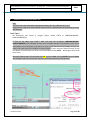
Let us draw Dining Room having 3.25 M x 4.15 M near the Kitchen. Assume Kitchen is already drawn
using the menu.
S1 - Start
S3 – Corner of the Kitchen is start point of line
Confidential to MCD
S2 – Use AutoCAD Line command to mark
wall thickness of 0.114 M
S4 – Wall thickness of 0.114 M is entered as end point
of the line by typing @0.114<0 (0 to draw horizontally)
Page 24 of 80
Online Building Plan Sanction User Manual - Building Plan - Fresh Residential Plotted Development
Architect
S5 – Terminate the line command by press Enter
Again. Drawn 0.114 M line.
S7 – Expecting start point of rectangle; click at end
of the 0.114 line
Confidential to MCD
MCD
S6 – Select Dining Room from the menu as shown
S8 – Can select second point if we have already marked
the diagonal point or we can go for Dimension
Page 25 of 80
Online Building Plan Sanction User Manual - Building Plan - Fresh Residential Plotted Development
Architect
S9 – Type D and press Enter
MCD
S10 – Enter length 3.25
S11 – Enter width 4.25
Confidential to MCD
Page 26 of 80
Online Building Plan Sanction User Manual - Building Plan - Fresh Residential Plotted Development
MCD
Architect
S12 – Enter height 3
S13 – Dining room has been drawn
S14 – Erase the 0.114 line which was drawn to mark
The wall thickness
Confidential to MCD
Page 27 of 80
Online Building Plan Sanction User Manual - Building Plan - Fresh Residential Plotted Development
Architect
MCD
TIPS:
In case of selecting Rectangle and Dimension then based on the start point of the rectangle and the
required position of the rectangle (as like in the quadrant) the Length and Width need be entered with
negative or positive value as follows.
Confidential to MCD
Page 28 of 80
Online Building Plan Sanction User Manual - Building Plan - Fresh Residential Plotted Development
MCD
Architect
Polyline
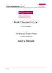
Polyline option can be used in case the room shape is irregular (including curved shape).
Let us draw a ‘L’ shaped Store room near the Kitchen. Assume Kitchen is already drawn using the menu.
S1 - Start
S2 – Use AutoCAD Line command to mark
wall thickness of 0.114 M
S3 – Corner of the Kitchen is start point of line
S4 – Wall thickness of 0.114 M is entered as end point
of the line by typing @0.114<0 (0 to draw horizontally)
Confidential to MCD
Page 29 of 80
Online Building Plan Sanction User Manual - Building Plan - Fresh Residential Plotted Development
MCD
Architect
S5 – Terminate the line command by press Enter
Again. Drawn 0.114 M line.
S6 – Select Store Room from the menu
S7 – Giving option to select start point of Rectangle
or Polyline
Confidential to MCD
S8 – Type P and press Enter to select Polyline
option
Page 30 of 80
Online Building Plan Sanction User Manual - Building Plan - Fresh Residential Plotted Development
MCD
Architect
S9 – Click end point of 0.114 M line to specify
start point of the store room
S11 – Type @2.25<0 to draw a line horizontally
Left to right and press Enter
Confidential to MCD
S10 – Expecting next point to be selected
S12 – After drawing 2.25 M line expecting next
point to be selected
Page 31 of 80
Online Building Plan Sanction User Manual - Building Plan - Fresh Residential Plotted Development
Architect
S13 - Type @0.5<90 to draw a line vertically
Bottom to top and press Enter
S15 - Type @1<0 to draw a line horizontally left to
right and press Enter
Confidential to MCD
MCD
S14 – Expecting next point
S16 - Type @1.75<90 to draw a line vertically
Bottom to top and press Enter
Page 32 of 80
Online Building Plan Sanction User Manual - Building Plan - Fresh Residential Plotted Development
MCD
Architect
S13 - Type @3.25<180 to draw a horizontal line right
to left and press Enter
S15 – Closed polygon created and expeting dimesions
Confidential to MCD
S14 – Expecting next point for line; press Enter to
snap with the strat point of the Polyline
S16 – Enter length of the room (3.25)
Page 33 of 80
Online Building Plan Sanction User Manual - Building Plan - Fresh Residential Plotted Development
MCD
Architect
S17 - Enter width of the room (1.75)
S19 – Store room is created.
Confidential to MCD
S18 – Enter clear height of the room (3.1)
S20 – Erase the line (0.114) that was drawn to
mark the wall thickness
Page 34 of 80
Online Building Plan Sanction User Manual - Building Plan - Fresh Residential Plotted Development
Architect
MCD
TIPS:
In case of polyline (irregular shape room) user need to enter length and width of the biggest rectangle
which can be fitted inside the irregular shaped room.
Use @2.25<0 to draw polyline. In this example 2.25 is length of the polyline to be drawn and 0 is angle
at which it has to draw.
@2.25<0 draw horizontal line left to right
@2.25<90 draw vertical line bottom to top
@2.25<180 draw horizontal line right to left
@2.25<270 draw vertical line top to bottom
@2.25<45 draw inclined line at 450 bottom to top
Confidential to MCD
Page 35 of 80
Online Building Plan Sanction User Manual - Building Plan - Fresh Residential Plotted Development
Architect
6.2.3
MCD
Site Plan
Draw in 1:1 scale in Meter. Following features can be captured based on the requirement.
Plot Area(For Site Plan)
Adjacent Plot(NTS)
Adjacent Park(NTS)
Building Area
Setback Area
Street
Open Area
Garage Servant Building
Boundary Wall
Confidential to MCD
Page 36 of 80
Online Building Plan Sanction User Manual - Building Plan - Fresh Residential Plotted Development
Architect
6.2.4
MCD
Plan
Draw in 1:1 scale in Meter. Plans of Basement, Stilt, Ground floor and upper floors can be drawn
with the help of following menus.
6.2.5
Floor Area
Dwelling Area
Room
Building Features
Parking
Garage
Section
Draw in 1:1 scale in Meter. Sectional view is used to determine the Building Height. Following
sectional view features can be drawn in this view.
o
o
o
o
Confidential to MCD
Groundline
Basement
Plinth
Stilt
Page 37 of 80
Online Building Plan Sanction User Manual - Building Plan - Fresh Residential Plotted Development
Architect
o
o
o
o
MCD
Ground Floor
Other Floors
RCC Height
Headroom Height
Use Line1 to Line6 of Miscellaneous to represent other sectional features like wall, door,
widow, balcony, parapet wall, room, stair etc.
Sectional line in the Plan can be drawn using Line1 to Line6.
Each Sectional view should be enclosed with Section Box.
6.2.6
Elevation
Use Line1 to Line6 of Miscellaneous to represent elevation features.
Each Elevation view should be enclosed with Elevation Box.
Confidential to MCD
Page 38 of 80
Online Building Plan Sanction User Manual - Building Plan - Fresh Residential Plotted Development
MCD
Architect
6.2.7
Paper Size
All the drawn entities should be enclosed with suitable paper size with appropriate scale.
As many paper size as required can be used based on the requirement.
Do not stretch the paper size.
While fitting the entities inside the paper size, take due care to move the polygon (outer
box) and corresponding text together without stretching or changing its integrity.
6.2.8
Complete
Upon completion of the drawing before final save, press Complete button.
6.2.9
Mandate Features
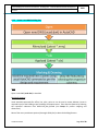
The tool is designed to prepare building plan of a plot having many buildings; each building has many
floors; each floor has many dwelling units; each dwelling unit has many rooms and building has common
features like lift, shaft, passage etc…
Hence following features are mandate in each building plan
Plot Area
Covered Area (One for each building should be drawn and minimum one is mandate)
Confidential to MCD
Page 39 of 80
Online Building Plan Sanction User Manual - Building Plan - Fresh Residential Plotted Development
Architect
MCD
Floor Area (At least Ground Floor should be drawn)
Dwelling Area (At least one should be drawn)
Rooms (Kitchen or Kitchen and Dining, Bed room, Toilet or Bath Room or Bath and Water Closet
or Water Closet)
Other features based on the requirement
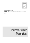
6.2.10 Drawing Curved features
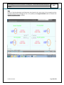
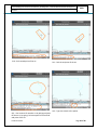
Curved features can be drawn by selecting Polyline option in most of the menus.
S2 – Enter building number
S3 – Type P and press Enter to select Polyline
S1 – Select Covered Area
S4 – Pick start point of the building
S5 – After picking the start point pick the second
point
Confidential to MCD
Page 40 of 80
Online Building Plan Sanction User Manual - Building Plan - Fresh Residential Plotted Development
Architect
S6 – Pick next point
S8 – Type A and press Enter to switch from line to arc
Confidential to MCD
MCD
S7 – Pick next point
S9 – Type S to select option of picking second
point of the arc
In case you want to pick end of the arc in this
stage directly pick the end point (typing S is not
Required)
Page 41 of 80
Online Building Plan Sanction User Manual - Building Plan - Fresh Residential Plotted Development
MCD
Architect
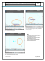
S10 – Pick second point of the arc
S12 – Can continue for another arc by picking end point
Of the arc or by typing S to have option of second and
end point of the arc
Confidential to MCD
S11 – Pick the end point of the arc
S13 – Type L to switch to line option
Page 42 of 80
Online Building Plan Sanction User Manual - Building Plan - Fresh Residential Plotted Development
Architect
MCD
S15 – Pick end of line segment and press Enter to
close the polyline
S14 – Pick end of line segment
TIPS:
In the polyline type A and press Enter to
switch between line to arc.
In the polyline type L and press Enter to
switch between arc to line.
There is no limit in switching between
line and arc and vice versa.
S16 – Curved feature has been created
Confidential to MCD
Page 43 of 80
Online Building Plan Sanction User Manual - Building Plan - Fresh Residential Plotted Development
MCD
Architect
6.2.11 Key plan/ Layout plan / Part Layout Plan
Key plan / Layout plan / Part Layout Plan should be drawn in the drawing in suitable scale using the
menu provide.
TIPS:
Need not to draw in 1:1 scale in Meter
6.2.12 Name plate / Certificates / Area chart / Parking chart
Name plate, Certificates like water harvesting, structural stability etc, area chart and parking chart are
need to be shown in the building plan DWG. Tool will automatically calculate and populate in the final
plot PDF.
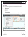
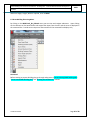
6.2.13 Others
If any of already set (by tool) layer color and background color are same the drawn feature will not be
visible, hence change the background color as follows
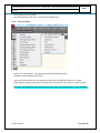
1. Type Options in the command line and press Enter
2. Click on Display tab
3. Click Colors… button
4. Click on Color button on top right side of the ‘Drawing Windows Color’ dialog box
5. Change the color which is not already used by the layers
If you want to load usual AutoCAD menu please load from the following path based on your AutoCAD
version
C:\Users\<User Name>\AppData\Roaming\Autodesk\AutoCAD Map 3D 2012\R18.2\enu\Support
Either or all of the below menus can be loaded.
custom.cuix / custom.mun / custom.cui
acad.cuix / acad.mnu / acad.cui
The tool will place text inside the rectangle / polyline drawn. The text should not be moved outside of
the respective rectangle / polyline.
While drawing few features like room, door, window etc. an auto sequential number is generated by the
tool to represent the feature in the report. If there is any gap is introduced in the sequential number
due to deletion of the feature will not affect the building plan. Hence need not bother about the auto
number generated by the tool.
Press Enter to close the feature (in the Polyline option) without picking the start point again.
Press Enter to terminate the command which draws line or arc like boundary wall, parapet wall etc.
Confidential to MCD
Page 44 of 80
Online Building Plan Sanction User Manual - Building Plan - Fresh Residential Plotted Development
Architect
MCD
Wherever Height, Length, Width is required, enter in Meter
6.3 Draw Building Plan using Menu
By clicking on the MCD-Fresh_Res_Plotted menu, we can view and navigate submenus. Upon clicking
on the submenu as like AutoCAD the tool expects few input from the user and the same is displayed in
the command line. Provide correct input one after another till the command line displays only
Command:
Before starting to prepare building plan go through and practice “Convert existing DWG building plan“,
“Create a new DWG building plan” and “Drawing Curved features” sections.
Confidential to MCD
Page 45 of 80
Online Building Plan Sanction User Manual - Building Plan - Fresh Residential Plotted Development
Architect
6.3.1
MCD
Site Plan
Site plan should be drawn in 1:1 scale in Meter.
Should be used to draw only plan views.
Select Site Plan Plot Area (For Site Plan)
Either Rectangle or Polyline option can be used based on the shape of the plot.
It is a mandate feature in a building plan.
Select Site Plan Adjacent Plot (NTS)
Either Rectangle or Polyline option can be used based on the shape of the plot.
Adjacent plot will ask plot number.
Adjacent Plot area need not be in scale 1:1 (Not to scale)
Select Site Plan Adjacent Park (NTS)
Either Rectangle or Polyline option can be used based on the shape of the park.
Adjacent Park will ask Park Name to enter.
Adjacent Plot area need not be in scale 1:1 (Not to scale)
Select Site Plan Building Area
Either Rectangle or Polyline option can be used based on the shape of the Building.
Building Area will ask for building number.
Confidential to MCD
Page 46 of 80
Online Building Plan Sanction User Manual - Building Plan - Fresh Residential Plotted Development
MCD
Architect
Select Site Plan Setback Area
Four types of setback area are provided, based on our requirement we need select any
One of the setback area.
-Right Side: Right side setback area.
-Left Side: Left side setback area.
-Rear: Rear side setback area.
-Front: Front side setback area.
Either Rectangle or Polyline option can be used based on the shape of the setback.
Enter width of the setback.
Select Site Plan Street Existing Front (NTS)
Either Rectangle or Polyline option can be used based on the shape of the street.
Enter width of the street.
Enter street name. (In case the front street does not have name just press Enter)
It is a mandate feature in a building plan.
Select Site Plan Other Street (NTS)
Either Rectangle or Polyline option can be used based on the shape of the street.
Enter width of the street.
Enter street name for other street. (In case the front street does not have name just press Enter)
It is a mandate feature in a building plan.
Select Site Plan Open Area
Either Rectangle or Polyline option can be used based on the shape of the open area.
Open area can be enclosed / excluded by the covered area as shown in the below figure. While
Confidential to MCD
Page 47 of 80
Online Building Plan Sanction User Manual - Building Plan - Fresh Residential Plotted Development
Architect
MCD
calculating the coverage area, system will deduce the area of open area in both the cases.
Select Site Plan Northarrow
Pick a point to place North Arrow
Use AutoCAD Rotate command to re-orient as required
One North Arrow is mandate for site plan.
Select Site Plan Garage Servant Building
Enter Garage & Servant building no :
(Building No. should not be duplicated in the entire drawing)
Either Rectangle or Polyline option can be used based on the shape
Select Site Plan Boundary Wall
Select wall Front/Rear/Left/Right by typing starting letter of the wall side
Select Service Street / Front Street w.r.t which the boundary wall height is being measured by typing
starting letter
Enter Boundary wall height
Pick series of points as required (Curved boundary can be drawn by typing A to select Arc and can be
switched back to line by typing L in the command line)
Press Enter to terminate the polyline
Pick on the drawn polyline to select start point of the leader
Confidential to MCD
Page 48 of 80
Online Building Plan Sanction User Manual - Building Plan - Fresh Residential Plotted Development
Architect
MCD
Pick second point of the leader
Text will be placed by the tool to represent the boundary wall
6.3.2
Floor Area (Plan)
Draw in 1:1 scale in Meter. Coverage area would be calculated from this.
Should be used to draw only plan views.
Open area, Shaft and Interior court yard can be enclosed / excluded by the floor area. While
calculating the coverage area, system will deduce the area of open area, shaft etc in both the cases.
Each Floor Area should be drawn inside Plot Area (For Floors) and with reference to Plot boundary.
Confidential to MCD
Page 49 of 80
Online Building Plan Sanction User Manual - Building Plan - Fresh Residential Plotted Development
MCD
Architect
Area which has relaxation from coverage area like balcony, weather shade, cupboard (projected)
need to be excluded from the floor area as shown in the figure.
Select Floor Area (Plan) Plot Area (For Floors)
Pick a point to place the Plot area {which was already drawn using Plot Area (For Site Plan)}
Only one Plot Area (For Site Plan) should be present in the drawing.
Floor areas can be drawn inside Plot Area (For Floors)
Floor area should be inside Plot Area (For Floors).
All plot areas should identical.
Select Floor Area (Plan) Basement
Either Rectangle or Polyline option can be used based on the shape of the basement.
Enter building number for which the basement is being drawn.
Select Floor Area (Plan) Stilt
Either Rectangle or Polyline option can be used based on the shape of the stilt.
Enter building number for which the stilt is being drawn.
Select Floor Area (Plan) Ground Floor
Either Rectangle or Polyline option can be used based on the shape of the ground floor.
Enter building number for which the ground floor is being drawn.
Select Floor Area (Plan) Other Floors
Either Rectangle or Polyline option can be used based on the shape of the other floor.
Enter building number for which the floor is being drawn.
Enter the floor number for which the floor is being drawn. First floor number should be 1 and second
Confidential to MCD
Page 50 of 80
Online Building Plan Sanction User Manual - Building Plan - Fresh Residential Plotted Development
Architect
MCD
floor number should be 2 and so on.
Select Floor Area (Plan) Mezzine / Service Floor
Either Rectangle or Polyline option can be used based on the shape of the Mezzine / Service floor.
Enter building number for which the Mezzine / Service floor is being drawn.
Select Floor Area (Plan) Terrace
Either Rectangle or Polyline option can be used based on the shape of the terrace.
Enter building number for which the terrace is being drawn.
6.3.3
Dwelling Features (Plan)
Draw in 1:1 scale in Meter.
Should be used to draw only plan views.
Select Dwelling Features (Plan) Dwelling Area
Command prompt need input, hence displays Enter Dwelling no [Duplex/Triplex]:
Enter Dwelling number (should be unique for a floor) in case the dwelling unit is in single floor.
Type D if the dwelling unit is Duplex one and then enter dwelling number. While depicting next floor
of the duplex house enter the same dwelling number.
Type T if the dwelling unit is Triplex one and then enter dwelling number. While depicting next floors
of the triplex house enter the same dwelling number.
Either Rectangle or Polyline option can be used based on the shape of the dwelling unit.
Even though there is only one dwelling unit present in that floor, dwelling area need to be drawn just
over the floor area as like tracing.
Confidential to MCD
Page 51 of 80
Online Building Plan Sanction User Manual - Building Plan - Fresh Residential Plotted Development
Architect
MCD
Select Dwelling Features (Plan) Balcony
Either Rectangle or Polyline option can be used based on the shape of the balcony.
Enter railing height of the balcony.
Balcony should be drawn outside of the floor area and dwelling area.
Select Dwelling Features (Plan) Cupboard
Either Rectangle or Polyline option can be used based on the shape of the cupboard.
Enter partition distance of the cupboard
Press enter if the cupboard is not projected outside
Type Y and press Enter if the cupboard is project outside
Select Dwelling Features (Plan) Door
Draw rectangle between two rooms to represent door
Pick start point of the leader line on the just drawn rectangle (should be inside the room)
Pick second point of the leader line
Enter door code (only integer is allowed; Prefix letter D is not required)
In case to represent Door Window press Enter and enter door code (only integer is allowed; Prefix
letter DW is not required)
To represent opening, glass etc Line1 to Line6 commands from Miscellaneous menu can be used
Select Dwelling Features (Plan) Door /Opening / Arch Table
Pick insertion point to place the predefined table
Confidential to MCD
Page 52 of 80
Online Building Plan Sanction User Manual - Building Plan - Fresh Residential Plotted Development
Architect
MCD
Enter height and width of the door / door window / Opening / Arch in the table as shown in the
figure
To increase the number of rows in the table double click on the bottom most right cell and press Tab
as many times as many needed rows.
Select Dwelling Features (Plan) Loft
Either Rectangle or Polyline option can be used based on the shape of the loft.
Enter the distance from ceiling and press Enter
Select Dwelling Features (Plan) Opening/Arch
Either Rectangle or Polyline option can be used based on the shape of the Arch.
Enter the opening/Arch code number as per table.
Select Dwelling Features (Plan) Window
Draw rectangle between room and floor area to represent window
Pick start point of the leader line on the just drawn rectangle (should be inside the room)
Pick second point of the leader line
Enter window code (only integer is allowed; Prefix letter W is not required)
In case to represent Ventilator press Enter and enter ventilator code (only integer is allowed; Prefix
letter V is not required)
To represent glass Line1 to Line6 commands from Miscellaneous menu can be used
Confidential to MCD
Page 53 of 80
Online Building Plan Sanction User Manual - Building Plan - Fresh Residential Plotted Development
Architect
MCD
Select Dwelling Features (Plan) Window Table
Pick insertion point to place the predefined table
Enter height and width of the window / ventilator in the table
To increase the number of rows in the table double click on the bottom most right cell and press Tab
as many times as many needed rows.
Confidential to MCD
Page 54 of 80
Online Building Plan Sanction User Manual - Building Plan - Fresh Residential Plotted Development
MCD
Architect
6.3.4
Room (Plan)
Draw in 1:1 scale in Meter.
Should be used to draw only plan views.
Height difference between floor finish and ceiling bottom need to be given as Room height
Select Room (Plan) Kitchen
Either Rectangle or Polyline option can be used based on the shape of the kitchen.
Enter room height
The above procedure can be adopted to draw following room features
Kitchen and Dining
Pantry
Dining Room
Bed Room
Living Room
Drawing Room / Living Room
Drawing Room and Dining Room
Dressing Room
Study Room
Store Room
Confidential to MCD
Page 55 of 80
Online Building Plan Sanction User Manual - Building Plan - Fresh Residential Plotted Development
MCD
Architect
6.3.5
Toilet
Bath Room
Bath and Water Closet
Water Closet
Veranda
Servant Quarters (Plan)
Draw in 1:1 scale in Meter.
Should be used to draw only plan views.
Height difference between floor finish and ceiling bottom need to be given as Room height
Select Servant Quarters (Plan) Servant Quarters
Enter the floor number for the Servant Quarters
Either Rectangle or Polyline option can be used based on the shape of the room.
Enter room height.
Select Servant Quarters (Plan) Servant Cooking Veranda
Either Rectangle or Polyline option can be used based on the shape of the room.
Enter room height.
The above procedure can be adopted to draw following Servant room features
Servant Room
Servant Bath Room
Confidential to MCD
Page 56 of 80
Online Building Plan Sanction User Manual - Building Plan - Fresh Residential Plotted Development
Architect
MCD
Servant Water Closet
6.3.6
Building Features (Plan)
Draw in 1:1 scale in Meter.
Should be used to draw only plan views.
Select Building Features (Plan) Corridor
Either Rectangle or Polyline option can be used based on the shape of the corridor.
Select Building Features (Plan) Canopies
Confidential to MCD
Page 57 of 80
Online Building Plan Sanction User Manual - Building Plan - Fresh Residential Plotted Development
MCD
Architect
Either Rectangle or Polyline option can be used based on the shape of the corridor.
Enter clearance height
Select Building Features (Plan) FireExit Ext Landing
Either Rectangle or Polyline option can be used based on the shape of the landing.
Select Building Features (Plan) FireExit Ext Stair
Enter height of Raiser
Enter number of steps
Pick start point of rectangle and end point of the rectangle
If the direction of steps are OK then press Enter
If the direction of the steps to be drawn perpendicular then type Y and press enter
Select Building Features (Plan) Hand Rail
Enter Hand rail height
Pick series of points as required (Curved boundary can be drawn by typing A to select Arc and can be
switched back to line by typing L in the command line)
Press Enter to terminate the polyline
Pick on the drawn polyline to select start point of the leader
Pick second point of the leader
Text will be placed by the tool to represent the Hand Rail
Select Building Features (Plan) Interior Courtyard
Either Rectangle or Polyline option can be used based on the shape of the interior courtyard.
Enter Building Number
Enter Interior courtyard number (Should be identical in all the floor plans)
Enter height of the court yard from road center line
Select Building Features (Plan) Lift (As per BIS)
Enter Lift number (Should be identical in all the floor plans)
Either Rectangle or Polyline option can be used based on the shape of the lift.
Select Building Features (Plan) Lift Pit
Enter Lift pit number
Either Rectangle or Polyline option can be used based on the shape of the lift pit.
Select Building Features (Plan) M/C Room (As per BIS)
Either Rectangle or Polyline option can be used based on the shape of the Mechanical room.
Enter Building Number
Select Building Features (Plan) Mumti
Either Rectangle or Polyline option can be used based on the shape of the Mumti.
Enter Building Number
Select Building Features (Plan) Ledge Tand
Enter height from the finished floor level
Either Rectangle or Polyline option can be used based on the shape of the Ledge Tand.
Confidential to MCD
Page 58 of 80
Online Building Plan Sanction User Manual - Building Plan - Fresh Residential Plotted Development
Architect
MCD
Select Building Features (Plan) Lobby / Lounge
Either Rectangle or Polyline option can be used based on the shape of the Lobby / Lounge
Select Building Features (Plan) Lift Lobby
Either Rectangle or Polyline option can be used based on the shape of the Lift Lobby.
Select Building Features (Plan) Open Area
Adopt same steps as like Site Plan Open Area
Select Building Features (Plan) Parapet Wall
Pick series of points as required (Curved boundary can be drawn by typing A to select Arc and can be
switched back to line by typing L in the command line)
Press Enter to terminate the Polyline
Pick on the drawn Polyline to select start point of the leader
Pick second point of the leader
Enter Parapet wall height
Text will be placed by the tool to represent the parapet wall
Select Building Features (Plan) Passage
Either Rectangle or Polyline option can be used based on the shape of the passage
Select Building Features (Plan) Pergola
Enter pergola height
Either Rectangle or Polyline option can be used based on the shape of the pergola
Select Building Features (Plan) Pergola Void
Either Rectangle or Polyline option can be used based on the shape of the pergola void
Select Building Features (Plan) Shaft
Either Rectangle or Polyline option can be used based on the shape of the shaft.
Enter building number
Enter shaft number (Should be identical in all the floor plans)
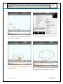
Select Building Features (Plan) Spiral Stair
Click center point of the circle
Enter radius of circle
Select the drawn circle
Pick a point to place the dimension of the stair
Select Building Features (Plan) Stair
Enter height of Raiser
Enter number of steps
Pick start point of rectangle and end point of the rectangle
If the directions of steps are OK then press Enter
If the direction of the steps to be drawn perpendicular then type Y and press enter
Confidential to MCD
Page 59 of 80
Online Building Plan Sanction User Manual - Building Plan - Fresh Residential Plotted Development
Architect
MCD
Select Building Features (Plan) Stair Landing
Either Rectangle or Polyline option can be used based on the shape of the landing.
Select Building Features (Plan) Garage
Either Rectangle or Polyline option can be used based on the shape of the Garage. (Either at Stilt or
Ground floor level)
Enter Headroom Height.
One and only Parking should have been drawn inside Garage
Select Building Features (Plan) Weather Shade
Enter height which is measured from finished floor
Either Rectangle or Polyline option can be used based on the shape of the weather shade.
Confidential to MCD
Page 60 of 80
Online Building Plan Sanction User Manual - Building Plan - Fresh Residential Plotted Development
Architect
6.3.7
MCD
Floor Height (Section)
Draw in 1:1 scale in Meter.
Should be used to draw only sectional views.
Height difference between floor finish and ceiling bottom need to be represented in the floor height.
RCC Height can be used to represent RCC thickness + floor finish
Select Floor Height (Section) GroundLine
To represent average ground level this menu can be used.
Pick serious of point to draw the line
Select Floor Height (Section) Basement 1 (Above Ground Level)
To represent basement portion which is above ground level (with ventilators) this menu can be used
Enter building number for which this basement is being drawn
Either Rectangle or Polyline option can be used based on the shape of the basement (Use polyline in
case of sunken slab)
Select the longest vertical line to mark the height and pick a point where the dimension needs to be
placed
Select Floor Height (Section) Basement 2 (Below Ground Level)
Confidential to MCD
Page 61 of 80
Online Building Plan Sanction User Manual - Building Plan - Fresh Residential Plotted Development
Architect
MCD
To represent basement portion which is below ground level (without ventilators) this menu can be used
Enter building number for which this basement is being drawn
Either Rectangle or Polyline option can be used based on the shape of the basement
Select the longest vertical line to mark the height and pick a point where the dimension needs to be
placed
TIPS:
B1 & B2 go together, hence both B1 & B2 should present or both should not be there in the DWG
Select Floor Height (Section) Basement 3 (Basement completely below Ground Level)
To represent basement which is completely below ground level (without ventilators) this menu can be
used
Enter building number for which this basement is being drawn
Either Rectangle or Polyline option can be used based on the shape of the basement (Use polyline in
case of sunken slab)
Select the longest vertical line to mark the height and pick a point where the dimension needs to be
placed
Select Floor Height (Section) Plinth
Enter building number for which this plinth is being drawn
Either Rectangle or Polyline option can be used based on the shape of the plinth (Use polyline in case of
sunken slab)
Select the longest vertical line to mark the height and pick a point where the dimension needs to be
placed
Select Floor Height (Section) Stilt
Enter building number for which this stilt is being drawn
Either Rectangle or Polyline option can be used based on the shape of the stilt (Use polyline in case of
sunken slab)
Select the longest vertical line to mark the height and pick a point where the dimension needs to be
placed
Select Floor Height (Section) Ground Floor
Enter building number for which this ground floor is being drawn
Either Rectangle or Polyline option can be used based on the shape of the ground floor (Use polyline in
case of sunken slab)
Select the longest vertical line to mark the height and pick a point where the dimension needs to be
placed
Select Floor Height (Section) Other Floor
Enter building number for which this floor is being drawn
Enter floor number for which this floor is being drawn
Either Rectangle or Polyline option can be used based on the shape of the ground floor (Use polyline in
case of sunken slab)
Select the longest vertical line to mark the height and pick a point where the dimension needs to be
placed
Repeat this command to draw all the floors from first to topmost floor
Confidential to MCD
Page 62 of 80
Online Building Plan Sanction User Manual - Building Plan - Fresh Residential Plotted Development
Architect
MCD
Select Floor Height (Section) RCC Height
Either Rectangle or Polyline option can be used based on the shape of the RCC (Use polyline in case of
sunken slab)
Select the longest vertical line to mark the height and pick a point where the dimension needs to be
placed
Select Floor Height (Section) Headroom Height
Pick start point (top of landing)
Pick end point (bottom of just above landing)
Select the vertical line to mark the height and pick a point where the dimension needs to be placed
Select Floor Height (Section) Total Height
Pick start point (Bottom most point of Stilt / Ground floor / B1)
Pick end point (Top most of top most RCC)
Select the vertical line to mark the height and pick a point where the dimension needs to be placed
Select Floor Height (Section) Section Box
Each sectional view should be enclosed by the section box
Pick start point of the rectangle
Pick end point of the rectangle
Enter name of the section (Ex: Section AA)
Move the text appropriately
6.3.8
Parking (Plan)
Confidential to MCD
Page 63 of 80
Online Building Plan Sanction User Manual - Building Plan - Fresh Residential Plotted Development
Architect
MCD
Draw in 1:1 scale in Meter.
Should be used to draw only plan views.
Tool will generate the parking chart, hence Architect need not populate in the drawing
Select Parking (Plan) Automated Multi Level
Either Rectangle or Polyline option can be used based on the shape of the automated multi level parking
Above method can be used to draw following parking feature
6.3.9
Basement Parking
Ground Floor Covered / stilt
Multi Level
Open Parking
Layout (Plan)
Draw in 1:1 scale in Meter.
Should be used to draw only layout views.
Tool will generate the Layout,
Select Layout (Plan) Layout Polyline (NTS)
Polyline option can be used based on the shape of the Layout
Layout Polyline need not be in scale 1:1 (Not to scale)
Select Layout (Plan) Layout Text
Pick start point the text.
Confidential to MCD
Page 64 of 80
Online Building Plan Sanction User Manual - Building Plan - Fresh Residential Plotted Development
Architect
MCD
Enter rotation angle.
Enter the required text.
To terminate press Enter twice.
Layout Polyline need not be in scale 1:1 (Not to scale)
6.3.10 Miscellaneous
Draw in 1:1 scale in Meter.
Can be used in plan, site plan, section, elevation etc.
In case there is no command available to draw any of the features (may be required for MCD’s approval
/ Owner of the building) please use the following commands. For example there is no room command
available to draw in the section or elevation, in this scenario use Line1 to Line6 to graphically represent
the feature and Text command can be used to mark type of room.
Line1
Line2
Line3
Line4
Line5
Line6
Confidential to MCD
Page 65 of 80
Online Building Plan Sanction User Manual - Building Plan - Fresh Residential Plotted Development
Architect
MCD
Text
Select Miscellaneous Line1
Pick series of points as required (Curved boundary can be drawn by typing A to select Arc and can be
switched back to line by typing L in the command line)
Press Enter to terminate the polyline
The same steps can be followed to use Line2 to Line6
Select Miscellaneous Text
Pick start point the text
Enter rotation angle
Enter the required text
To terminate press Enter twice
TIPS:
If text height need to be changed modify the same by double clicking and enter the required value in
Text Height field
Various line type / line weight can be set for Line1 to Line6 to differentiate in the plotting.
Type Layer press Enter and change line type or line weight can be changed as required
6.3.11 Others
Select Others Elevation Box
Confidential to MCD
Page 66 of 80
Online Building Plan Sanction User Manual - Building Plan - Fresh Residential Plotted Development
Architect
MCD
Select first corner of the box
Select second corner of the box
Enter elevation name
Move the name appropriately
Each elevation view should be enclosed inside the Elevation box
TIPS:
Line1 to Line6 can be used to draw elevation view
Select Others Linear Dimension
Pick start point of the object from where the dimension to be measured
Pick end point of the object up to where the dimension to be measured
Wherever dimension is required use this command
Select Others Leader
Pick start point the leader
Pick as many points as required
Enter to terminate the leader
Type the required Annotation
Press Enter to terminate Annotation
Press Enter to terminate the command
6.3.12 Paper
This command can be used to enclose the drawn features with required paper size boundary. Based on
the plot area either 1:50 or 1:100 scale can be selected.
Confidential to MCD
Page 67 of 80
Online Building Plan Sanction User Manual - Building Plan - Fresh Residential Plotted Development
Architect
MCD
Select Paper A0-1:100
In case the plot area is more than 250 sq. mt. use this 1:100 scale paper size.
Pick the insertion point; a 6 sided polygon will be inserted by the tool
Move the drawn objects inside the polygon. (While moving ensure all the layers are unlocked and take
care both polygon and their related text are moved together without changing their integrity)
This six sided polygon can be moved, but should not be stretched / modified
As many polygons (different paper sizes A0 / A1 / A2) as required can be used for a single building plan.
No objects can be kept outside of the paper boundary.
Same steps can be applied to be below commands too.
A1-1:100
A2-1:100
A0-1:50
A1-1:50
A2-1:50
Confidential to MCD
Page 68 of 80
Online Building Plan Sanction User Manual - Building Plan - Fresh Residential Plotted Development
Architect
MCD
6.3.13 Complete
Select Complete.
Before final save of the DWG press Complete button.
TIPS:
While preparing the building plan save frequently to avoid losing your work, before final save press
Complete button and then Save.
Confidential to MCD
Page 69 of 80
Online Building Plan Sanction User Manual - Building Plan - Fresh Residential Plotted Development
Architect
MCD
6.4 Dos
1.
2.
3.
4.
Use Model space to draw
hould not use other than specified layers
Elevation use only MCD_Line1 to 6 inside MCD_Elevation box ..
While using *.VLX, if the respective text is out of the rectangle / polygon, need to be moved
inside – if required can be scaled
6.5 Don’t
1. Do not press Esc / Ctrl + C during the command is being
executed (i.e. till the tool displays Command: - Till such time
carefully read the command line and provide appropriate
input)
2. Do not delete / modify the text which was placed by the tool
3. Do not move the text (which was placed by the tool) outside the polygon
Confidential to MCD
Page 70 of 80
Online Building Plan Sanction User Manual - Building Plan - Fresh Residential Plotted Development
Architect
7.
MCD
Frequent Mistakes to be avoided
Following errors are frequently made by the Architect. Please take necessary steps to avoid the
same.
1.
2.
3.
4.
5.
6.
7.
8.
Without loading VLX trying draw the features using the menu
Using old VLX / MNU to draw building plan
Using non-relevant building type VLX / MNU to draw building plan
Using other than specified layers
Deleting / modifying relevant text for the feature (Ex: KD,2,3)
Related text not present in the respective layer
Related text not inside the PLINE
Using Educational version of AutoCAD to prepare building plan
TIPS: To remove Education stamp
Step 1: Open the file in AutoCAD
Step 2: Save as AutoCAD 2000 / LT 2000 DXF (*dxf) – provide path to save
Step 3: Open new drawing (use acad.dwt template) from non educational version of AutoCAD
Step 4: Type DXFIN in command line and select the DXF created in step 2 and then save as
*.DWG
Confidential to MCD
Page 71 of 80
Online Building Plan Sanction User Manual - Building Plan - Fresh Residential Plotted Development
Architect
8.
MCD
Guideline to correct the Validation error
TIPS:
Here Text means the code used to represent the feature (Ex: DI,2,3.000, B-2,O,F-3 etc.)
Polygon means single line having multiple vertices to form a required shape of the feature (Ex: room,
floor area etc.)
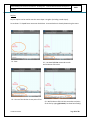
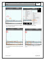
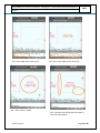
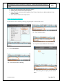
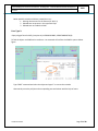
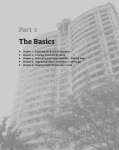
Error Type 1:
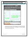
No description text found in polygon Object handle 93C79 at (60859.6954812057,11850.6778406472,0)
To find out the object type ‘PLINE / LINE’ and enter the co-ordinate (60859.6954812057,11850.6778406472); that would be the start point the PLINE and then click anywhere on the screen
(alternatively use scroll button of the mouse to zoom to the start point of the PLINE), and you can
zoom to the start point of the PLINE to reach the object. If there are many features present at that
co-ordinate list each features one by one to find the Object handle 93C79. Below figure will provide
more clarity.
Alternative (abbreviation of find handle) type FH and press Enter and type 93C79 then press Enter,
tool will draw a red color circle at the start point the feature and zoom to that location.
Confidential to MCD
Page 72 of 80
Online Building Plan Sanction User Manual - Building Plan - Fresh Residential Plotted Development
MCD
Architect
Below possible mistake could have created the error:
1. Missing relevant text for the feature (Ex: KD,2,3)
2. Related text not present in the respective layer
3. Related text not inside the PLINE
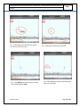
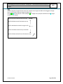
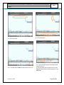
Error Type 2:
Open polygon found in MCD_Canopies At (112706.83204895,-35820.7800805769,0)
To find the object use PLINE and co-ordinate. List command will confirm the PLINE is open as below
figure.
Type ‘PEDIT’ command and select the object and type ‘C’ to correct the mistake.
Alternatively erase the polyline and corresponding text and redraw with the help of menu.
Confidential to MCD
Page 73 of 80
Online Building Plan Sanction User Manual - Building Plan - Fresh Residential Plotted Development
MCD
Architect
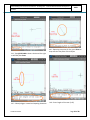
Error Type 3:
MCD_Cupboard not having expected syntax for Object handle 9B1AB at (60884.9875723905,11852.773984551,0) (Ex:CUP,1,PN,1.5)
Syntax of the text is not as required. Please erase the polyline and corresponding text and redraw
with the help of menu.
Error Type 4:
Text does not have corresponding polygon - (71336.8624401434,-11509.5434415597,0)
Zoom to the feature using the co-ordinate as explained in Error Type 1
Below possible mistake could have created the error:
1. Polygon might have deleted
2. Polygon might have open error as like Error Type 2
3. Text might have been moved outside of the polygon
4. There could have more than one text inside the polygon
Alternatively erase the test and corresponding polyline (if found) and redraw with the help of menu.
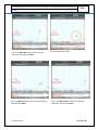
Error Type 5:
MCD_Dwelling_Area is outside of the MCD_Floor_Area - Object Handle :9A23 - (71302.228479689,11494.5065364262,0)
Zoom to the feature using the co-ordinate as explained in Error Type 1
Analyze which and where polygon / part of polygon is outside the floor area. Correct by stretching /
moving vertices etc.
TIPS:
Confidential to MCD
Page 74 of 80
Online Building Plan Sanction User Manual - Building Plan - Fresh Residential Plotted Development
MCD
Architect
The error need not be at the mentioned co-ordinate, can be anywhere along the polygon’s perimeter
Error Type 6:
Drawing can not open, Please upload valid dwg
Below possible mistake could have created the error:
1. The drawing would not have drawn using AutoCAD 2004 to 2012
2. The drawing would have drawn using AutoCAD educational version
3. While open new drawing (before start up the drawing) would not have selected
acad.dwt
Draw using proper AutoCAD version and resubmit
Error Type 6:
Mtext is not allowed in Mcd_Dim1 - (58530.2248305979,580.597717228828,0)
AutoCAD Mtext is not allowed in that specific layer.
Other Errors:
S.
No.
1.
2.
3.
Error Message
Possible Mistake
No -MCD_Boundary code found to polygon Object
handle
334B
(58610.2389367934,596.89578193664,0)
Line is not allowed in MCD_Stair (26.8158445248272,34.2273456312266,0)
Object out side the paper polygon, Handle : 21EE
Relevant text placed by tool would
have been deleted / moved / modified
Line was drawn in specific MCD layer –
not allowed
Few object might have been placed
outside paper polygon – move them
inside appropriately
Two polygons were drawn in such a
way that they are overlapping each
other (will give error even it is a very
small overlap - check all along the
perimeter of the polygons)
Two polygons were drawn in such a
way that they are overlapping each
other (will give error even it is a very
small overlap - check all along the
perimeter of the polygons)
Two relevant texts were inside the
polygon
4.
MCD_Setback_Area Object Handle :8AA8 overlaped
with MCD_Setback_Area Object Handle :8AA6 (71429.4571296521,-11501.4020108369,0)
5.
MCD_Building_Area Object Handle :1AB1 overlaped
with MCD_Setback_Area Object Handle :8AA8 (71414.3169009809,-11478.9323884147,0)
6.
More than one description text found in polygon
Object handle 8AA8 - (71429.4571296521,11501.4020108369,0)
The 'MCD_Building_Area' should be exist.
Mandate feature is missing
Sectional views are not enclosed by Section box
Sectional view should have enclosed
7.
8.
Confidential to MCD
Page 75 of 80
Online Building Plan Sanction User Manual - Building Plan - Fresh Residential Plotted Development
Architect
9.
10.
11.
12.
13.
14.
15.
16.
17.
18.
19.
20.
with Section box
In sectional view corresponding floor is
missing – need to create the floor in
section or delete the floor plan
No Window table and Door Table found
Window table is missing
The mandatory layer MCD_Street not found
Mandate feature is missing
ZValue
not
allowed
in
mtext
- Feature / text might have drawn /
(58585.2916626477,594.522576754466,modified in such a way that it has Z
4.73532645018253E-22)
value – always Z value should be zero
Invalid layer( WALL) found in dwg, Please remove
Feature / object present in non MCD
layers
Corresponding Building number(1) not found in
Building number mismatch between
Building Area Site plan building and plan floor area /
(58533.1754386406,584.086540668749,0)
sectional floor
Corresponding Floor area not found in plan view for In sectional view corresponding floor is
:B-1,B,F-0
missing – need to create the floor in
section or delete the floor plan
No dimension found to floor height object handle
Dimension is missing in the section
AF4D8 - (58574.2291724889,611.437674196982,0
Both B1 and B2 basements should exist Both B1 & B2 should coexist – one is
(58555.3219419304,622.261693274972)
not allowed
Window/Door number not exist in tables Corresponding door / window number
(58585.5678518972,583.395792427787,1.59209485 is missing the door / window table
43468E-21)
Irregular polygon present Object Handle :AEF51 While drawing polygon, vertex over
(58623.7279297934,593.047227436727,0)
vertex were placed – please erase
polygon and corresponding text and
redraw
No Window/Door number found for object handle
Door / window is missing plan present
347D - (58553.7367898517,571.973395864703,0)
in door table. In case Door polygon /
Arrow / Door code (text) missing or
the leader is exploded, this error
message will be shown.
Extra Floor area found in plan view at
:(2485.58478275698,511.790437834266,0)
21.
Lift should not be present in terrace and basement :
22.
Mumti and MC room should be only on the terrace :
handle 123A - (615.2389367934,96.89578193664,0)
23.
There should be atleast one parking area in garage :
handle 123A - (615.2389367934,96.89578193664,0)
24.
There should be no door or opening arch in lift pit :
handle 123A - (615.2389367934,96.89578193664,0)
There should be no lift pit outside basement: handle 123A
- (615.2389367934,96.89578193664,0)
There should be no lift in basement : handle 123A (615.2389367934,96.89578193664,0)
25.
26.
MCD
Confidential to MCD
Lift was drawn in terrace or Basement –
Please remove
Either Mumti or Machine room present
outside of the terrace – move them into
terrace
No Parking area in garage -At least one
parking should exist in garage – draw
parking area in garage
Existing of door or opening arch in lift pit Please remove
Lift pit is placed in other floors – move it
to basement
Lift present in Basement – Please remove
Page 76 of 80
Online Building Plan Sanction User Manual - Building Plan - Fresh Residential Plotted Development
MCD
Architect
27.
28.
29.
30.
31.
32.
33.
34.
35.
36.
37.
38.
39.
40.
41.
42.
43.
44.
45.
46.
47.
48.
49.
There should be no servant area in the terrace/stlit :
handle 123A - (615.2389367934,96.89578193664,0)
There should be atleast one spiral staircase in the servant
quarters : handle 123A (615.2389367934,96.89578193664,0)
There should be atleast one bath or watercloset in the
servant quarters : handle 123A (615.2389367934,96.89578193664,0)
There should be no door connecting lift lobby and
staircase Handle: handle 123A (615.2389367934,96.89578193664,0)
Setback should cover entire side: handle 123A (615.2389367934,96.89578193664,0)
Setback having more than 4 sides are not allowed: handle
123A - (615.2389367934,96.89578193664,0)
The Basement is not equal or less than the ground floor: :
handle 123A - (615.2389367934,96.89578193664,0)
There should be atleast one door/opening arch in each :
room
The Basement should 2M from adjoining properties:
handle 123A - (615.2389367934,96.89578193664,0)
MCD_101_Plot_Area_Floor is not identical with Plot area :
handle 123A - (615.2389367934,96.89578193664,0)
There should be no floor area without plot area: handle
123A - (615.2389367934,96.89578193664,0)
There is no adjacent plot or park or street :
615.2389367934,96.89578193664,0)
Cupboard should be inside the floor area: handle 123A (615.2389367934,96.89578193664,0)
Duplex found in only one floor : handle 123A (615.2389367934,96.89578193664,0)
Triplex found in only in 2 floors: handle 123A (615.2389367934,96.89578193664,0)
Paper Size polygon should be exist in the dwg :
(615.2389367934,96.89578193664,0)
Paper size polygon modifed: handle 123A (615.2389367934,96.89578193664,0)
Paper scale should be 1:100 only for above 250 SQMT
plot area: handle 123A (615.2389367934,96.89578193664,0)
Paper scale should be 1:50 only for below 250 SQMT plot
area : handle 123A - (615.2389367934,96.89578193664,0)
Stilt should not have Dwellings and rooms :
(615.2389367934,96.89578193664,0)
Landing width is not equal to its stair :
(615.2389367934,96.89578193664,0)
Dimension overlapping with another dimension :
(615.2389367934,96.89578193664,0)
In dimension layer unwanted object found: handle 123A -
Confidential to MCD
Servant area present in the terrace/stlit –
Please remove
At least one spiral staircase should exist
for servant quarters – draw spiral staircase
At least one bath or watercloset should
exist in servant quarters – draw bath or
watercloset in servant quarters
Door / Opening present between lift lobby
and staircase lobby – remove it
Setback was not drawn as per the bye-law
requirement
Setback having more than 4 sides – make
sure Setback have 4 sides
The Basement is not equal or grater than
the ground floor
No door exist in room –
Distance between Basement and adjoining
properties is less than 2 M
MCD_101_Plot_Area_Floor was modifed –
not allowed
Floor area should be drawn inside
MCD_101_Plot_Area_Floor
Adjoining properties is missing
Cupboard is placed outside of the floor
area – move it to inside of the floor area
Duplex present only one floor
Triplex present only 2 floors
Paper size polygon is missing in the DWG Paper Size polygon should be exist in the
dwg
Paper size polygon has been modified.
Not selected appropriate scale
Not selected appropriate scale
Dwelling or room was drawn in stilt –
Remove it.
Landing width and stair are not equal
Two Dimensions were drawn in such a way
that they are overlapping each other
Not relevant objects / features present –
Page 77 of 80
Online Building Plan Sanction User Manual - Building Plan - Fresh Residential Plotted Development
Architect
50.
51.
52.
53.
54.
(615.2389367934,96.89578193664,0)
Empty section box is not allowed
(615.2389367934,96.89578193664,0)
Coexistence of Basement, Plinth, Ground floors are not
allowed RCC does not exist for floor object: handle 123A (615.2389367934,96.89578193664,0)
Atleast one ground floor should exist in the plan
Building no(4) not used in floor area
55.
Corresponding Building number(4) not found in Building
Area
56.
MCD_Room is outside of the MCD_Dwelling
615.2389367934,96.89578193664,0)
MCD_Plot is not exist :
615.2389367934,96.89578193664,0)
MCD_Kitchen is overlayed MCD_bed :
615.2389367934,96.89578193664,0)
57.
58.
59.
The 'MCD_Plot_Area' should be only one
60.
61.
62.
63.
MCD_Plot_Area' should be exist
The 'MCD_Building_Area' should be exist
MCD_Dwelling_Area' should be exist
The 'MCD_Street' should be exist.
64.
The 'MCD_Street' should be only one
65.
Only WC and DRE can have 7 Feet wall redraw the room
66.
Invalid layer MCD_poly found in dwg, Please remove
67.
68.
The mandatory layer 'MCD_Plot_Area' not found
not having expected syntax for Object handle
(58610.2389367934,596.89578193664,0)
'MCD_Building_Area' is outside of the "'MCD_Plot_Area "
- Object Handle 334B (58610.2389367934,596.89578193664,0)
69.
70.
No 'MCD_Building_Area' exist in MCD_Plot_Area
71.
Drawing cannot open, Please upload valid dwg
Confidential to MCD
MCD
Remove the same
Missing the section view
Coexistence of Basement, Plinth, Ground
floors
RCC is missing for the floor
Ground floor is missing
Site plan building do not have
corresponding plan – mismatch of building
number could be a reason
Corresponding building for plan is missing
in site plan – mismatch of building number
could be a reason
Room is outside of the Dwelling area –
move it to inside
Plot area is missing
Two rooms were drawn in such a way that
they are overlapping each other (will give
error even it is a very small overlap - check
all along the perimeter of the rooms)
More than one Plot area has been drawn –
only one is allowed (Plot Area is different
from Plot Area Floor)
Plot Area is missing
MCD_Building_Area is missing
MCD_Dwelling_Area is missing
MCD_Street is missing. Please draw the
MCD_Street'
More than one 'MCD_Street' has been
drawn using Exiting Front command.
7 feet height wall has been drawn other
than WC & Dressing room.
Invalid layer was found. Please Remove
invalid layer.
Missing mandate feature
Text placed by the tool was modified –
delete text and polygon and redraw.
'MCD_Building_Area' is outside of rhe
MCD_Plot_Area. Please make sure
'MCD_Building_Area' is inside
MCD_Plot_Area
Existing of 'MCD_Building_Area' is not in
MCD_Plot_Area. Please make sure
'MCD_Building_Area' is inside
MCD_Plot_Area
Drawing was drawn using Educational
version of AutoCAD or some other SW –
Page 78 of 80
Online Building Plan Sanction User Manual - Building Plan - Fresh Residential Plotted Development
Architect
MCD
need to draw using AutoCAD 2004 – 2009
MCD will introduce new validation checks and incorporate the same as and when required, would be
self explanatory and above sample errors can be referred back to understand better.
Bye-law report is self explanatory one.
Confidential to MCD
Page 79 of 80
Online Building Plan Sanction User Manual - Building Plan - Fresh Residential Plotted Development
Architect
9.
MCD
Feedback / Help Line
We have put our best effort to make this tool user friendly and we are improving on continues basis.
We welcome your feedback to enhance further.
Assumption:
AutoCAD know person having though understanding of the instruction
provided in the user manual has explored to the best of his ability before
approaching feedback / help line.
Mail: [email protected]
Phone: 011 23227411 / 13 / 14
Confidential to MCD
Page 80 of 80