1
“Survey Says”...page 6
A PUBLICATION OF MENTOR GRAPHICS NOV 2010—VOLUME 6, ISSUE 3
Chief Verification Scientist Harry
Foster introduces our newest
Verification Academy module,
Verification Planning, and shares
results from a poll conducted
through our Verification Academy
program.....more
New Methodologies: They
Don’t Have to Be Scary.
By Tom Fitzpatrick, Editor
and Verification Technologist
Firmware Verification Using
SystemVerilog OVM page 8
... implementing a new OVM environment
from scratch, replacing a previous e-based
environment. more
SystemVerilog Configurable Coverage Model in an OVM Setup page 14
... an elegant way to handle SystemVerilog’s
limited flexibility in covergroups. more
Advanced Techniques for AXI
Bus Fabric Verification page 25
... introducing the concept of a virtual fabric
that helps you tackle the challenges of
complexity and schedule pressure. more
Converting Module-Based
Verification Environments
to Class-Based Using
SystemVerilog OOP page 34
...wrap your existing code with a class-based
layer, taking advantage of the reusability and
modularity of OOP code while maintaining
backward compatibility with your existing
environment. more
Verifying a CoFluent SystemC IP
Model from a SystemVerilog UVM
Testbench in Questa page 38
... use an OVM testbench to verify SystemC
IP, with Cofluent Studio—a graphical modeling
and simulation environment that can generate
SystemC TLM code automatically. more
What You Need to Know About
Dead-Code and X-Semantic Checks.
page 44... introducing a variety of ways
to adopt formal verification without writing
properties or assertions. more
My daughter recently celebrated her 10th birthday.
We’ve always had her birthday parties at our house,
but this year was different for two reasons. First, now
that Megan has reached “double-digits,” we let her
have a sleepover party, which meant there were six
nine- and ten-year-old girls sleeping in our basement
that night. Second, since Megan’s birthday is right
around Halloween, she decided to make that the theme of the party. My wife had a great time
getting all the decorations and games together for the party, and on the big night our guests
were treated to everything from light-up ghosts
to tombstones on the front lawn, cobwebs on the
“It all comes down to
ceilings and even a giant spider hanging from the
kitchen ceiling. But the biggest surprise of all was
building on the familiar
Megan’s costume.
Having spent most of the previous Halloweens
as a princess of some sort or other, Megan decided
that this year would be different. She wanted to
be a vampire! My wife used her theatrical makeup
experience to good use, painting Megan’s face white
and including some “blood” dripping from her mouth.
With her beautiful auburn hair hidden under a black
wig, Megan didn’t look like my little girl at all. But, of
course, it was still her underneath.
while pushing the
boundaries a bit and
stepping a little outside
your comfort zone.”
—Tom Fitzpatrick
I’m sure by now you’re wondering what this has to do with Verification Horizons. Megan’s
party reinforced the idea that, when you step outside your comfort zone, sometimes you can
achieve better results than you might have imagined. But there are still some important things
to remember. We were able to build on past experience to take typical party games and add a
spooky flair to them so that they would both fit the theme of the party and also be great fun for
the girls, and we even thought up a couple of new games, too. Big brother David helped keep
everything on schedule so we could fit everything in (including presents and cake!) and we
even managed to get the girls to bed at a reasonable time (for a girls’ sleepover, anyway). And
lastly, we were able to adapt as the night wore on so that, even though we didn’t do everything
we had originally planned, we got the important things done and everyone had fun.
Let’s see…planning, building on experience, adding new features, tracking progress,
managing schedules, achieving results. My daughter’s party was an engineering project!
In this issue, we’re going to show you how all of these ideas fit into
adopting a new verification methodology, or improving your current
methodology.
Our first article, from our good friend and colleague Harry Foster,
“The Survey Says,” introduces our newest Verification Academy
module, Verification Planning. It also shares the first round of results
from a poll conducted through our Verification Academy program. This
article sets the stage for the discussions to follow by letting you see
how you compare to your colleagues who have visited the academy.
Our feature article, “Firmware Verification Using SystemVerilog
OVM,” comes from our friends at Infineon in Singapore, who
worked closely with some of my Mentor Graphics colleagues to
implement a layered OVM-based methodology to verify a power
train microcontroller. Interestingly, they chose to implement their new
OVM environment from scratch to replace their previous e-based
environment. As you’ll see, they were able to take advantage of OVM’s
ability to provide structure to the environment, as well as flexibility in
reusing the structure for a variety of tests. This will now form the basis
for additional projects moving forward.
Our next article was written by our friends at Applied Micro, who
share their thoughts on reusability in “SystemVerilog Configurable
Coverage Model in an OVM Setup.” This shows a clever bit of
coding in which the covergroups are written in terms of configurable
parameters that can be controlled using the OVM set/get_config
mechanism to let you modify the covergroups on a per-test basis.
It even shows how to use a similar approach to configure cover
properties as well. I’ve heard many SystemVerilog users complain to
various degrees about the lack of flexibility in covergroups, and this
article shows how to handle it quite well.
In “Advanced Techniques for AXI Bus Fabric Verification,” the
authors introduce the concept of a virtual fabric that helps you
tackle the challenges of complexity and schedule pressure. Using
a combination of a virtual model of the fabric along with Mentor’s
unique algorithmic stimulus generation techniques, you’ll be able to
implement and debug most of your environment while the RTL is still
being designed. The article discusses how these techniques were
applied to an actual project, so you’ll see the issues and benefits they
encountered.
We realize that many of you are still testing the waters a bit
when it comes to Object-Oriented Programming and adopting new
methodologies like OVM. In the spirit of “walk before you run,” we next
present an article from one of my colleagues in India, which discusses
“Converting Module-Based Verification Environments to Class-Based
Using SystemVerilog OOP.” Rather than abandoning what may be
2
a substantial amount of module-based Verilog or SystemVerilog
code, this article will show you how to wrap your existing code with
a class-based layer to begin to take advantage of the reusability and
modularity of OOP code while maintaining backward compatibility with
your existing environment. From there, it’s a straightforward step to
fully adopt something like OVM.
In our Partners’ Corner this issue, we present “Verifying a CoFluent
SystemC IP Model from a SystemVerilog UVM Testbench in Mentor
Graphics Questa” from our friends at CoFluent Design. This article
shows you how to use an OVM testbench to verify SystemC IP.
Cofluent Studio provides a graphical modeling and simulation
environment that lets you generate SystemC TLM code automatically.
As you’ll see, it can also generate the Questa DPI code and custom
C++ code needed to seamlessly integrate that TLM code into your
OVM environment, which can itself be partially reused as the design is
refined to RTL.
And last but not least, we have an article from my formal verification
colleagues, Ping Yeung and Erich Marschner, on “What You Need to
Know About Dead-Code and X-Semantic Checks.” In this article, you’ll
be introduced to some ways of adopting formal verification without
having to write properties or assertions. Dead-Code and X-Semantic
checks are two of the areas where our new automatic formal checking
can be used to augment dynamic simulation. I think you’ll see
that being able to add this new technology on top of your existing
methodology will prove extremely useful.
As you can see, we spend a lot of time here at Mentor trying
to make it easier for you to adopt all this cool technology we’re
developing. It all comes down to building on the familiar while pushing
the boundaries a bit and stepping a little outside your comfort zone.
Don’t be afraid. What may look like a giant spider at first may turn
out to be just a balloon. I hope you enjoy this issue of Verification
Horizons.
Getting back to Megan’s party, I’m sure you parents out there can
sympathize with my difficulty in understanding how it could be that
we’re celebrating her tenth birthday when she was just born not too
long ago. I guess time really does fly when you’re having fun.
Respectfully submitted,
Tom Fitzpatrick
Editor, Verification Horizons
Hear from
the Verification
Horizons team
weekly online at,
VerificationHorizonsBlog.com
3
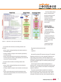
TABLE OF CONTENTS
Page 6...Survey
Says: Verification Planning
by Harry Foster, Chief Verification Scientist Design Verification Technology,
Mentor Graphics Corporation
Page 8...Firmware
Verification
Using SystemVerilog OVM
by Ranga Kadambi, Eric Eu, and Sudheer Arey, Infineon Singapore
Mark Glasser and Christoph Suehnel, Mentor Graphics Corporation
Page 14...A
SystemVerilog Configurable
Coverage Model in an OVM setup
by Parag Goel, Sr. Design Engineer and Sakshi Bajaj, Design Engineer II,
Applied Micro with Pushkar Naik, Sr. Staff Design Engineer, Applied Micro
and Ashish Kumar, Lead Application Engineer, Mentor Graphics Corporation
Page 25...Advanced
Techniques
for AXI Bus Fabric Verification
by Alain Gonier and Jay O’Donnell, Mentor Graphics Corporation
Page 34...Converting
Module-Based
Verification Environments to Class-Based
Using SystemVerilog OOP
by Amit Tanwar, Mentor Graphics Corporation
4
Partners’ Corner
Page 38...Verifying a CoFluent SystemC
IP Model from a SystemVerilog UVM
Testbench in Mentor Graphics Questa
by Laurent Isenegger, Jérôme Lemaitre and Wander Oliveira Cesário,
CoFluent Design
Page 44...What
you need to know
about dead-code and x-semantic checks
by Ping Yeung and Erich Marschner, Mentor Graphics Corporation
Verification Horizons is a publication
of Mentor Graphics Corporation,
all rights reserved.
Editor: Tom Fitzpatrick
Program Manager: Rebecca Granquist
Wilsonville Worldwide Headquarters
8005 SW Boeckman Rd.
Wilsonville, OR 97070-7777
Phone: 503-685-7000
To subscribe visit:
www.mentor.com/horizons
To view our blog visit:
VERIFICATIONHORIZONSBLOG.COM
5
Survey Says: Verification Planning
by Harry Foster, Chief Verification Scientist Design Verification Technology, Mentor Graphics Corporation
As the saying goes: Those who fail to plan, plan to fail. With that
said, I am excited to announce a new module focused on Verification
Planning, which has been one of the Verification Academy’s mostrequested subjects for new content. The new Verification Planning
module is delivered by our subject matter expert, who literally wrote
the book on the subject, Peet James. The goal of verification planning
and management is to architect an overall verification approach, and
then to document that approach in a family of useful, easily extracted,
maintainable verification documents that will strategically guide the
overall verification effort so that the most amount of verification is
accomplished in the allotted time. The aim of this module is to define
terms, logically divide up the verification effort, and lay the foundation
for actual verification planning and management on a real project. I
think you will really enjoy and be enlightened by Peet’s treatment of the
subject, and hopefully, you can apply many of the techniques that he
presents to your own projects.
Speaking of applying Verification Academy techniques—we
just conducted a large survey about the academy and found some
interesting results that I would like to share with you. First, Figure 1
shows who is viewing the Verification Academy content by job title.
Figure 2: Verification Academy
viewers by targeted design implementation
We are obviously seeing a growing number of FPGA engineers
interested in advanced functional verification. Today’s complex SoCbase FPGA designs are not your mom and pop variety of FPGA
designs. More advanced verification skills are required to ultimately
meet both quality and schedule goals.
Another question we wanted to answer through our survey is
whether the Verification Academy has been useful. One way to answer
this is to see how many viewers had actually applied or plan to apply
the knowledge they learned in the Verification Academy on their own
projects. The survey results are shown in Figure 3.
Figure 1: Verification Academy viewers by job title
Figure 3: Verification Academy viewers
It’s not too surprising that a majority of the viewers are verification
engineers, with a ratio of about 3.5 verification engineers for every 2
designers.
In addition to who is viewing the Verification Academy, we
were interested in learning the viewer’s type of targeted design
implementation to get a better understanding of our viewers’ needs.
Figure 2 shows who is viewing the Verification Academy by their type
of targeted design implementation.

6
who have applied knowledge on projects
We also wanted to determine through the survey if the content
presented in the Verification Academy was at an appropriate level
of detail. The survey results are shown in Figure 4.
Figure 4: Verification Academy
content level of detail
Finally, we wanted to determine through the survey which additional
topic in advanced functional verification should be covered in the
Verification Academy. Figure 5 presents the results.
Your feedback is important to us, and we are very excited that our
new Verification Planning module was one of the top requests from the
Verification Academy survey participants.
I would like to encourage you to check out all our new and
existing content at the Verification Academy by visiting www.
verificationacademy.com.
Figure 5: Verification Academy new subject content request
7
Firmware Verification Using SystemVerilog OVM
by Ranga Kadambi, Eric Eu, and Sudheer Arey, Infineon Singapore
Mark Glasser and Christoph Suehnel, Mentor Graphics
INTRODUCTION
Semiconductor design is changing rapidly, which in turn forces
continual evolution of verification methodologies and languages. This
change is happening across the board, affecting not only expensive
chips bound for big-iron servers but also more modestly priced
processors built for specific applications.
Consider the case of embedded microcontrollers. These integrated
blocks of processing capability, memory and programmable
peripherals are found in a range of products, from power tools to
toys. Their reach is in part due to their plunging cost. Today, 8-bit
microcontrollers, which account for the majority of all CPUs sold in the
world, sell for as little as $0.25 each. Consider that in the early 1970s,
Intel’s 8008, the world’s first 8-bit processor, sold for $120, an amount
roughly equal to $520 today.
Microcontrollers of course are niche devices, usually built for a small
handful of tasks. An engine microcontroller, for example, might take
input from various sensors and adjust fuel mix and spark plug timing.
However, the specificity of these chips does not equate to simplicity
in their design. High-end 32-bit Infineon microcontrollers bound for
various automotive applications have as many as 70 distinct IP blocks
that must be integrated and verified. And as it turns out, the hardware
challenges are only the half of it.
Like all microcontrollers, those designed by Infineon rely heavily
on firmware. The firmware is critical, and not just the higher-level
code that is closest to the application itself and that usually resides in
flash memory. The lower level boot read only memory (ROM) code
executes an increasing number of background processing tasks,
including bootstrap loading, memory checking and so on. As is true of
the hardware, the firmware itself is increasingly complex. Just a few
years back the firmware for Infineon’s automotive chips – the Munich,
Germany-based company is the No. 1 chip supplier to the automotive
industry – amounted to just a few hundred lines of code. Today the
firmware file is 16 kilobytes, and growing larger with each release.
For those writing the firmware, the challenge is a bit like building a
plane while flying it. Namely, they are writing software for early-stage
hardware that is nowhere near stable. How do you verify something
when everything – the individual IP blocks, the overall design, even
the firmware code itself – is still a work-in-progress? That was the
8
challenge in a recent pilot project to design and verify a power train
microcontroller at Infineon in Singapore.
The solution was a layered methodology. The first layer is
a standard Open Verification Methdology (OVM) testbench used
to drive input interfaces via constrained-random pattern generation,
observe outputs, measure functional coverage and compare the
results against expected values, a process known as scoreboarding.
(OVM is a joint development initiative between Mentor Graphics and
Cadence Design Systems to provide the first open, interoperable,
SystemVerilog verification methodology in the industry.) A second
layer implements a well-defined structure for observing (using the
SystemVerilog bind construct) and driving internal nodes in the VHDL
design (using SignalSpy™, a technology within the Mentor Graphics
Questa® Solution). We believe this combined approach will be more
widely used in the future.
FIRMWARE VERIFICATION METHODOLOGY
When building our new testbenches with OVM, our goal was to
use the same firmware verification methodology we used in e, a
verification language developed by Cadence and approved in IEEE
Standard 1647. We chose to start from scratch rather than migrate
portions of the e testbench to SystemVerilog because we did not have
an e Reuse Methodology (eRM)-compliant testbench. Additionally, it
would not be easy to migrate from e to OVM because of fundamental
language differences. This also gave us the opportunity to make all of
the OVM verification components (OVC) more structured, a contrast to
our former e environment.
Building an OVM testbench from scratch certainly takes a bit of
effort. For example, we needed to make our firmware verification
methodology fit the OVM technology and guidelines. Then, of course,
we had to build it. As the project progressed we definitely became
convinced that the OVM methodology and technology were quite
impressive and worth the initial effort to ramp up.
This effort to learn OVM took place against a backdrop of increasing
time and resources required to verify firmware in general. Five years
ago, verification of automotive Infineon microcontrollers took no more
than four man-months. Today we spend twice as long, largely due to
mounting complexity.
Even seemingly simple tasks can be confounding. Take, as a
hypothetical case, firmware written to toggle a particular port. It should
be straightforward enough to verify the code and check the ports that
are toggled. But what happens when there are additional conditions,
as is inevitably the case? Perhaps the firmware reads the counter
value from another address and is coded to toggle every set number
of cycles. And maybe there’s input from another pin that tells the code
whether the counter should be reset or just stopped with each toggle.
Verifying all this functionality at the design stage is flat out difficult,
especially with unverified underlying hardware.
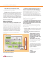
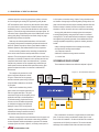
DESIGN DESCRIPTION
The design under test (DUT) is mainly coded in VHDL with some IP
blocks coded in Verilog. The DUT is instantiated by a VHDL top-level
testbench used for SoC verification (see Figure 1). The SystemVerilog/
OVM top-level is instantiated under this VHDL top-level.
In this project, we used the SystemVerilog bind construct to observe
the internal VHDL signals and the Mentor Graphics Questa SignalSpy
technology for driving them.
// testbench top
module top_tb_top;
top_tb_connect tb_ic();
top_tb_virtual tb_vif = new(“tb_vif”);
initial begin
// connect interfaces
tb_ic.connect_vif(tb_vif);
set_config_object(“ovm_test_top.*”, “ifc”, tb_vif, 0);
run_test();
end
endmodule
Code Sample 1
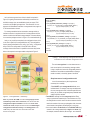
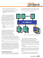
The second layer consists of the OVCs (see Code Sample 2). We
are using a proprietary OVC template and guidelines to develop these
verification components. The OVCs are configurable using parameters
and/or macros. TLM analysis ports and TLM analysis fifos are used
for the OVC interconnections. TLM analysis ports provide simple and
powerful transaction-based communication because of their ease of
implementation, support of multiple connections, and execution in the
delta cycle.
Figure 2: The OVM test environment.
Figure 1. VHDL top-level testbench.
OVM TEST ENVIRONMENT
The first layer test environment (see Code
Sample 1 and Figure 2) consists of an interface
layer for observing and driving signals into the DUT.
Firmware verification differs from the conventional
bus functional model (BFM) because we are mostly
interested in whitebox testing. Instead of a BFM
model, we used a signal map. The signal map is
a collection of internal signals that are relevant to
our verification goals. The signal map implements
methods for observing and driving internal signals.
9
// example of an OVC
class clkgen_agent extends ovm_agent;
protected ovm_active_passive_enum is_active = OVM_ACTIVE;
// TLM connections to other OVCs
ovm_analysis_port #(clkgen_item) aport;
// TLM output to other OVCs
ovm_analysis_export #(bootgen_item) bootgen_export;
// TLM input from other OVCs
// signal maps
ports_if cpu_if
ports_vif;
cpu_vif;
// global event pool
ovm_event_pool eventPool;
// components
clkgen_config clkgen_driver clkgen_sequencer clkgen_monitor clkgen_coverage cfg;
driver;
sequencer;
monitor;
coverage;
`ovm_component_utils_begin(clkgen_agent)
ovm_field_enum (ovm_active_passive_enum, is_active,
OVM_ALL_ON)
`ovm_field_object(cfg,
OVM_ALL_ON)
`ovm_component_utils_end
function new (string name, ovm_component parent);
super.new(name, parent);
aport = new(“aport”, this);
bootgen_export = new(“bootgen_export”, this);
endfunction
10
function void build();
ovm_object obj;
super.build();
// check if cfg has been created externally
if (cfg == null) begin
// fallback if cfg is not created outside
`ovm_info(get_type_name(), “Configuration
object not initialised from outside. Generating
one internally”, OVM_LOW)
cfg = clkgen_config::type_id::create(“cfg”, this);
assert(cfg.randomize());
end
// get signal map
if (get_config_object(“ports_vif”, obj, 0)) begin
assert($cast(ports_vif, obj))
else
`ovm_error(get_type_name(),
“Wrong virtual interface type!”)
end
else begin
`ovm_error(get_type_name(),
“Virtual interface not available!”)
end
// get signal map
if (get_config_object(“cpu_vif”, obj, 0)) begin
assert($cast(cpu_vif, obj))
else
`ovm_error(get_type_name(),
“Wrong virtual interface type!”)
end
else begin
`ovm_error(get_type_name(),
“Virtual interface not available!”)
end
// get global event pool
eventPool = ovm_event_pool::get_global_pool();
monitor = clkgen_monitor::type_id::create(“monitor”, this);
coverage = clkgen_coverage::type_id::create(“coverage”,
this);
if (is_active == OVM_ACTIVE) begin
driver = clkgen_driver::type_id::create(“driver”,this);
sequencer = clkgen_sequencer::type_id::
create(“sequencer”, this);
end
endfunction
function void connect();
super.connect();
// connect monitor resources
monitor.cfg = cfg;
monitor.cpu_vif = cpu_vif;
monitor.eventPool = eventPool;
if (is_active == OVM_ACTIVE) begin
// connect driver resources
driver.cfg = cfg;
driver.ports_vif = ports_vif;
driver.eventPool = eventPool;
driver.seq_item_port.connect(sequencer.
seq_item_export);
driver.dport.connect(coverage.analysis_export);
// connect driver TLM to coverage
driver.dport.connect(this.aport);
// connect driver TLM to agent
sequencer.cfg = cfg;
end
endfunction
endclass
Code Sample 2
OVCs are critical in helping us to deal with large numbers of IP blocks.
We can more or less map each such block to a corresponding OVC,
and together these OVCs interact and cross check at a high level in
such a way as to hide the lion’s share of the complexity. If a future
Infineon product incorporates a new or replacement block, we simply
need to add or swap out one OVC. Given the modular nature of OVC,
and of SystemVerilog in general, we can leave the rest of the stitched
together design mostly as is. This is a boon to the design team and
unusual in an era in which complexity often hides interdependence.
Tugging on one loose thread can often cause an entire digital fabric to
unravel.
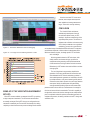
In general, in our firmware verification testbench we have four
types of OVCs: PC monitor, config generator, monitor/scoreboard,
and testbench element.
The PC (program counter)
monitor is the main OVC. It
is responsible for monitoring
the PC, decoding the PC, and
triggering an ovm_event when
the PC matches a label in the
firmware code. In addition, it
will collect PC data for code
and branch coverage. All
other OVCs in the testbench
need an object handle to this
PC monitor class. The config
generator OVC creates the
constrained-random stimulus
and feeds it into the DUT that
will influence the behavior of
the firmware execution. The
chief function of the monitor/
scoreboard OVC is to observe
and compare signals in the DUT against the stimulus generated by the
generator OVC in response to events triggered by the PC monitor (see
Figure 3). The monitor OVC contains the required functional coverage
points. It will be sampled by the covergroup only if all the conditions
and checks for a coverage point are met. The testbench element OVC
is usually a communication component that interacts with the DUT on
the port interfaces. Examples include the JTAG module and bootstrap
loaders. This OVC performs a specific task using the actual protocol of
the communication component.
The third layer is the top-level OVM environment and configuration
layer. The top-level environment instantiates all the OVCs and
creates the TLM connections. The top config block configures the
sub-configs in each of the OVCs for a specific DUT. A virtual top
sequencer controls the config generators, the OVC’s sequencer, and
the testbench element OVC’s sequencer. The top sequencer library
contains complex sequences involving two or more of the OVCs, such
as pipelined sequences whereby the output of one generator OVC is
needed by another generator OVC.
The fourth layer contains the OVM test pool. Each test specifies a
particular scenario to run in the testbench. The test pool configures
the environment by using the factory override methods.
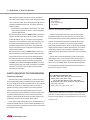
Figure 3: An example of event (PC) based
assertions in firmware verification.
11
FIRMWARE VERIFICATION RESULTS
Our verification focus in this project is the firmware, which is
assembly ROM code in the microcontroller. The firmware code
contains the very first instructions that will be executed by the
microcontroller upon boot up. A proper execution of the firmware upon
power-on must be ensured to bring the microcontroller to a functional
state. Any bug in the firmware that causes the startup to fail will render
the device unusable. Since the firmware code is hard-coded, a respin
of the chip would be necessary, driving up the cost of development
significantly.
We found 12 firmware bugs and five hardware bugs using the OVM
for firmware verification. Common firmware bugs were the result of
the implementation not meeting specification (these were detected
by assertions) or implementations that did not cover all possible
scenarios in the firmware (detected by random stimulus generation
and coverage). Firmware verification quite often also detects hardware
bugs (through assertions) caused by registers that are not writable or
readable because either their protections are not set correctly in the
RTL or their top-level connections are incorrect. Most significantly, we
hit verification targets related to functional coverage and code branch
coverage. The latter is a methodology in which we execute both trunk
and branch blocks of code, a technique that helps to deal with multiple
revisions, a fact of life in all software development.
EXPERIENCES AND LESSONS LEARNED
We were able to pursue our goal of constructive, meaningful
innovation in the sense that this was a successful pilot project using
OVM and SystemVerilog for firmware verification. The success during
the pilot convinced us that for subsequent projects we could reuse
most of our firmware test environment, especially the OVM portion.
OVM provides comprehensive guidelines for building a complete
verification environment. OVM extends tested and proven coveragedriven, constrained-random verification with practical resources in the
OVM class libraries. OVM facilitates reuse and configuration by using
the OVM factory method, and the TLM provides a standard and simple
data transaction between verification components. Another useful
feature was OVM Event, which helps to monitor the core program
counter so we can know at which stage the core is actually getting the
instruction in the firmware. Essentially we can trigger the feature at a
particular stage of the firmware’s execution. OVM Event propagates
to all OVCs, which do various assertions and checks on signals and
monitors. All told these OVM features enabled a reusable and modular
approach to design verification.
12
The OVM methodology and technology were quite impressive
and worth the initial ramp up. In the past for a project of this scale,
Infineon would generally spends perhaps six to nine man-months
on the firmware, though for this pilot we put in 10 man-months. One
reason is that compared to AOP, OOP does sometimes require more
lines of code. However, the extra lines of code required by OOP
enabled us to reach our primary goal of a more structured approach.
Importantly, our OVM infrastructure was well structured, a contrast to
our former e environment. Furthermore, the compile issues inherent
to AOP required an effort greater than that required to write the extra
lines of OOP code. On subsequent projects, the amount of effort and
workarounds associated with the OVM should also decline.
The main challenges we came across were in the first layer of
the verification architecture: implementing the bind mechanism to
connect to internal nodes of the VHDL design and feeding back these
connections into the OVM testbench. The objective was to provide
a complete language-based interface for observation and forcing of
internal nodes. So far, this objective was reached only with respect to
observation.
We resolved the control issue by using SignalSpy, a Questa
utility that provides access to internal design nodes to drive signals.
However, it is not a language-based approach. The employment of the
force functionality in SignalSpy conformed to OVM guidelines without
generating serious issues.
To avoid changing existing force files to accommodate testbench
development (required by the standard Infineon OVM testbench
architecture), the top-level testbench had to be VHDL. OVM does
not require a SystemVerilog top-level module. Therefore, this could
be easily managed. The implementation of testbench elements for
the design (JTAG, etc.) involved separate tasks and was performed
following the OVM guidelines.
FUTURE IMPROVEMENTS
The main challenge of this project was the implementation of the
signal map layer. The use of the SystemVerilog bind construct was
not suitable for whitebox verification because the construct is not
reusable if the design changes. Furthermore, SystemVerilog bind has
its limitation with VHDL designs.
For future improvements, we would like to explore the possibility of
replacing the signal map with an OVM register package to access the
internal registers of the DUT, and we are aware that a register package
will be provided in the near future by the OVM organization. Once
available, this will solve the controllability issue.
SystemVerilog should be extended to improve the driving of internal
signals in VHDL designs. VHDL users will drive this demand to
improve the functionality of SystemVerilog for VHDL designs. This is
not an issue for Verilog portions of a design or IP.
Based on this pilot project, we recommend the following
enhancements to SystemVerilog:
1. Deliver improved documentation for the SystemVerilog bind
construct to make its employment easier and more powerful.
2. Provide a language-based approach to access internal nodes in
VHDL designs for observation and forcing.
13
A SystemVerilog Configurable Coverage Model in an OVM setup
by Parag Goel, Sr. Design Engineer and Sakshi Bajaj, Design Engineer II, Applied Micro with Pushkar Naik, Sr. Staff Design Engineer,
Applied Micro and Ashish Kumar, Lead Application Engineer, Mentor Graphics Corporation
With the advent of a new era in verification technology based on
an advanced HVL like SystemVerilog, the concept of random stimulus
based verification was born, to verify today’s multi-million gate
designs.
In concept, every verification engineer fancies the idea of random
stimuli driven verification, but as is rightly said – “Everything comes
with a cost” and the cost here is a big concern that haunts the life of
every verification engineer:
• How do I close my verification?
• When can I say I am done?
To answer such questions, SystemVerilog as a language came up
with the concept of Functional Coverage that is much more accurate of
a measure compared to the traditional Code Coverage techniques. We
concentrate mainly on this SV feature in our write-up, adding one more
dimension to it - configurability.
Methodology like OVM has brought in the concept of reusability of
Environment/Agent (mainly consisting of Driver/ Monitor/ Sequencer)
across projects. But, on the other hand, a user tends to create a
coverage model that is usually coupled very tightly to the specifications
of the given project. In the process, he/she ends up writing a separate
coverage model for every project, compromising the reusability aspect
and violating the Methodology mantra! Keeping above limitation in
view, we would like to present the user with one possible solution –
Configurable and Reusable Coverage Model, sighting AMBA AXI
protocol as the case study for discussion.
The paper is sub-divided in the following major sections:
1. Overview
a. Why configurable coverage model???
b. SystemVerilog coverage constructs – Key to configurability
2. Basic coverage setup
a. Overview of the AXI setup – agents/connections/passing
configuration
b. Classification of the coverage model – AXI as an example
c. Requirements of configurable model
3. In depth analysis of the coverage model (coding practices/
constructs used)
a. Transaction Coverage
14
b. Error Coverage
c. Protocol Coverage (AXI Handshake coverage) / Flow Coverage
4. Limitations faced
5. Concluding Remarks
OVERVIEW
Why configurable coverage model???
“To minimize wasted effort, coverage is used as a guide for directing
verification resources by identifying tested and untested portions of the
design.”
— IEEE Standard for SystemVerilog (IEEE Std 1800-2009)
This quote from LRM [2], explains the intent of functional coverage.
But the crux of this paper lies in the configurability of any given
coverage model. Configurability is the key to re-usability for any setup.
All our current day methodologies have brought in the concept of
reusability of the agents such as BFM’s and Monitors across projects.
In the same project, an engineer also creates a coverage model in
order to provide the management with a picture of the verification
activity status. However it’s as per the given project specifications.
Thus an engineer ends up having to write a separate coverage model
per project while re-using the rest.
However, verification environments created from reusability
perspective need to be meticulously designed to take care of coverage
model reusability as well! So our main focus is on the coverage model
that could be configured and re-used.
AMBA – AXI is one of the most commonly used protocols in industry
for communication among the SOC peripherals. Thus we chose this
protocol for our case study.
SystemVerilog Coverage constructs –
Key to configurability
SystemVerilog provides a very fast and convenient method to
describe the functional coverage for any given setup with the help of
pre-defined constructs. A brief overview shall be a good starting point.
A covergroup is user-defined type like a class, which defines a
coverage model. Composed of a number of sub-elements including
the following…
• Coverpoint - Describes a particular type of coverage event, how it
will be counted as well as one or more bins to organize the count
• Cross - Defines a new coverage event by “combining” two or more
existing coverpoints or variables
• Bin- A coverage event counting mechanism, automatically or userdefined
• Options - Certain built-in options that helps to gain better
controllability over the collection of coverage numbers.
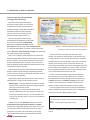
Figure-1 below depicts a brief overview. The main highlight of the
paper lies in the wise usage of the coverage/coverpoint/cross point
“OPTIONS”, “METHODS” and “BINS” provided in the language.
The following outlines a few important aspects.
Firstly, the important coverage options:
1. per_instance: Each instance contributes to the overall information
for the covergroup type. When true, coverage information for this
covergroup instance is tracked well.
2. at_least: Minimum number of hits for each bin. A bin with a hit
count less than this number is not considered covered.
Say for example, if we want a particular coverpoint/bin to be hit a
minimum of 5 times before user gains a confidence on the same,
user should specify option.at_least=5
3. weight: If set at the covergroup level, it specifies the weight of this
covergroup for computing the overall coverage. If set at coverpoint
(or cross) level, it specifies the weight of a coverpoint (or cross) for
computing the coverage
4. goal: Specifies the target goal for a covergroup. If the userspecified goal, say 50% for that given coverpoint/bin, then this
shall account towards 100% coverage calculation.
5. auto_bin_max: Maximum number of automatically created bins
when no bins are explicitly defined for a coverpoint.
All the options can be specified for instance-specific or type specific
coverage calculation. But language restricts that type_option must be
a constant parameter and does not allow variable for the same. The
only configurations provided are goal, weight, strobe and comment.
There is a key difference between type and instance coverage. The
instance coverage would give us coverage of each individual instance
created while type coverage is a sum of all instances. Type coverage
has many limitations which are described in later part of the paper.
Coverage methods are what we would discuss next.
1. sample(): Controls the triggering of a covergroup.
2. get_coverage(): Calculates type coverage number (0-100)
3. get_inst_coverage(): Calculates the coverage number (0-100)
of a specific instance on which it is invoked.
Since these methods can be called procedurally at any point of
time, gives the user an additional flexibility to control the collection
of coverage for a defined covergroup as well as get the coverage
numbers in any of the agents in your OVM setup say, a score-board
etc.
Now let’s look into a little detail of bins:
[open_range_list] specification - one of the important features in
the bin definition that enables the user to control the number of bins
created in case the user has explicitly defined the bins, since the
option auto_bin_max doesn’t work in
this case.
Another point that we have utilized
is the order of precedence that the
language imposes on the illegal/
ignore/normal bin definition. The
priority order is as:
1. illegal_bins: doesn’t account
towards overall coverage, issues an
error
Figure 1 : SystemVerilog
Coverage Constructs - Overview
15
2. ignore_bins: doesn’t account towards overall coverage
3. bins: are user-defined/automatically created collectors which
count towards the overall coverage numbers.
“The default specification is associated with each of the above bins.
It defines a bin that is associated with none of the defined value bins.
The default bin catches the values of the coverage point that do not lie
within any of the defined bins. However, the coverage calculation for
a coverage point shall not take into account the coverage captured by
the default bin. The default bin is also excluded from cross coverage.”
BASIC COVERAGE SET-UP
Overview of the AXI setup
As shown in Figure 2, we have built our coverage model in an OVMbased setup. Utilization of OVM’s TLM communication to build the
hierarchy run-time helps a user in the placement of the components
as required and also provides ease-of-communication amongst the
components. As evident, all the regular components of the VIP are
placed inside an agent wrapper. For the visibility of the collected
transaction we utilize analysis port-export connection to establish
a link between the bus monitor and the score-board as well as the
coverage collector. The main reason for this structure is that both
these components are coded by a user as per project specific
requirements.
But later, with the introduction of the generic coverage model, we
were able to shift this coverage collector inside the agent itself. Still
it follows the same TLM connection along with an enable/disable
switch attached to its connection in the connect() phase of OVM.
This is the first level of control for the coverage model, as we
don’t start focusing on the coverage numbers right from the start of
the project, hence we need to keep it disabled until we gain first cut
confidence on the design as well as the verification environment setup.
Classification of the coverage model –
AXI Protocol as an example
As we rely mainly on our coverage definition for verification closure,
so a comprehensive coverage model definition is required. Towards
this end, a modular coverage model divided into 4 sections as shown
below would yield great results.
But this modular coverage classification can still be considered
generic in the sense that every protocol can be categorized under
these same 4 sections.
• Transaction coverage: coverage definition on the user-controlled
parameters usually defined in the transaction class & controlled
through sequences.
• Error coverage: coverage definition on the pre-defined error
injection scenarios
• Protocol coverage: (AXI Handshake
coverage) this is protocol specific. In the
case of AXI, it is mainly for coverage on
the handshake signals i.e. READY & VALID
on all the 5 channels.
• Flow coverage: This is again protocol
specific and for AXI it covers various features
like, outstanding, inter-leaving, write data
before write address etc…
Consolidating all the above 4 models in a
modular & easily controllable fashion was the
next task. The figure below describes how it
was done in an OVM setup.
Following are the basic requirements
to model these 4 coverage models:
Figure 2 : Overview of the AXI setup
16
1. Interface
2. Transaction collected
3. Configuration class
Let’s see how we get each one of them in detail. As depicted in
Figure 3, for getting the transactions collected by bus monitor into
the Main coverage class, we established a basic port-export TLM
connection with the Main coverage class. This transaction is in turn
passed to the Write/Read Transaction coverage model class, again via
a TLM communication channel.
For coverage models other than transaction coverage model, an
interface connection is required such that it is shared across the Bus
monitor as well as the individual coverage models. This was achieved
via connection package as shown in Figure 3. For more details refer [1]
Lastly, a very crucial input required is the configuration class, which
in our case is specific for coverage definition only. This configuration
class is passed and utilized via set_config_*/get_config_* configuration
utility of OVM. The configuration is set by the user in the main
coverage class and from there it is passed via the same utility further
below to the respective coverage models as depicted in Figure 3.
function void build();
super.build();
if(cov_cfg.disable_transaction_coverage == 0) begin //{
axi_trans_cov = axi_transaction_coverage# (ADDR_WIDTH…)
::type_id::create(“axi_trans_cov”, this);
end //}
if(cov_cfg.disable_error_coverage == 0) begin //{
axi_error_cov = axi_error_coverage# (ADDR_WIDTH…)
::type_id::create(“axi_error_cov”, this);
end //}
if(cov_cfg.disable_axi_handshake_coverage == 0) begin //{
axi_handshake_cov = axi_handshake_coverage# (ADDR_WIDTH…)
::type_id::create(“axi_handshake_cov”, this);
end //}
if(cov_cfg.disable_flow_coverage == 0) begin //{
axi_flow_cov = axi_flow_coverage# (ADDR_WIDTH…)
::type_id::create(“axi_flow_cov”, this);
end //}
endfunction
Listing 1 : Code depicting coverage model classes
controlled via user controlled configuration class
The main coverage class is a class that serves as a
basic control point for the remaining coverage models.
Listing 1 depicts the first level of configurability based on
whether the user wishes to enable/disable a coverage
model as a whole, in the build() phase of the OVM.
Requirements of configurable model
Let us first summarize very basic requirements
necessary for re-usability.
Figure 3 : Coverage Model – OVM setup
Note: As per the SV LRM, since the covergroup(s) can be
created only in the class constructor, we should have the
configuration object available from the user in the class
constructor itself, despite the fact that we use OVM set/get
configuration methods usually in the build() phase of an
OVM setup. We shall talk more about this in the later
section of the paper.
• Turn ON/OFF each coverage model defined, on an
individual basis. For example, user may not always want
the error coverage to be ON, until he/she performs error
testing. So, by default, we generally keep it disabled and
enable only when required.
• Turn ON/OFF coverage for each covergroup defined. Every
covergroup should be created only if a user wishes to do so. So
this configuration control is used in the class constructor itself to
restrict the creation of the covergroup altogether. Also, the same
control needs to be applied at the sampling of a covergroup.
• User must be able to set the limits on the individual field being
covered in the coverage model within a legal set of values. Say
for example, transaction field like, Burst Length - user should be
17
able to guide the model on what are the limits on the field that
one wishes to get coverage on within a legal set of values ranging
from 1-16 as per AXI spec. So providing lower and upper limits for
transaction parameters like burst size, burst length, address etc.
makes it re-usable.
o option.weight can be exploited for this purpose. Thus, weight
of only those coverpoints can be set to 1 which are legal and
within user defined limits
• User should be able to control the number of bins to be created
and the limits within which they should be created, for example
in fields like address. auto_bin_max option can be exploited to
achieve this, in case user doesn’t specify the bins explicitly. This
can also be achieved by specifying the number of bins to be
created as parameter to the bins construct, which works when
there are user defined bins. So a legitimate choice needs to be
made from above options.
• User must be able to control the number of hits for which a bin
can be considered as covered. option.atleast can be used for this
purpose and the input to this can be a user defined parameter
• User should also have the control to specify his coverage goal,
i.e. when the coverage collector should show the covergroup
“covered” even though the coverage is not 100%. This can be
achieved by using option.goal, where goal is again a user defined
parameter. This is useful in various applications as illustrated
in the later part of this paper.
IN DEPTH ANALYSIS OF THE COVERAGE MODEL
Transaction Coverage
Transaction class in terms of methodology is a class that contains
all the randomizable properties contributing towards complete testing
of a given design. But unless all the possible values of every individual
parameter as well as set of combinations of each one of them, is
applied to the design, gaining confidence on our testing is difficult.
However, even after one has created several random test cases,
how can one be sure that the verification is complete and that he has
covered all possible scenarios? Thus it is of utmost importance to
building a coverage model that will let the verification engineer know
quantitatively how much he/she has been able to achieve.
In order to get a better understanding of this coverage model, let us
consider an example from AXI. There are several parameters in AXI
which should be tested and checked for corner case hit. Some of them
are mentioned in the Listing 2.
18
Burst Length, Burst
Size, Burst Type,
Access Type, Response
Type, Address ……
Listing 2 : AXI Transaction parameters
Although it is essential to check corner case hits from protocol
specification perspective, but at the same time, it’s very important
that exact hits relevant to one’s project specification get checked. For
example, AXI spec does provide limits for parameter Burst Length
from 1 to 16, but it is important to check for the values relevant to
ones project specification and not as per AXI specification (assuming
project specifies a subset of values supported by AXI). This is where
configurability takes the lead. Not having a configurable coverage
model might give us false numbers which are of no use to the specific
project.
Also we need to ensure that duplication of code can be avoided
while coding the same coverpoint across various covergroup(s) (i.e.
individual covergroup for a given property and while defining it’s cross
points). Here in the example below we have taken BurstLength from
AXI to illustrate the same Macro for burst length and burst size has
been shown in Listing 3 & Listing 4.
`define CMG_BURST_ADDR_WRITE_LEN() \
CP_BURST_ADDR_WRITE_LEN: coverpoint trans.BurstLength {\
bins CB_BURST_ADDR_WRITE_LEN[] =
{[cb_wr_lower_blen_limit:cb_wr_upper_blen_limit]}; \
illegal_bins CB_BURST_ADDR_WRITE_LEN_ILLEGAL = default; \
option.weight = wght_blen; \
option.at_least = cb_wr_blen_min_hit_count; \
}
Listing 3 : Macro definition for covergroup – Burst length. Here
legal bins are defined within user configured limits, rest all are
treated as illegal. Weight i.e. enable/disable & hit-count are also
set by the user.
`define CMP_BURST_ADDR_WRITE_SIZE() \
CP_BURST_ADDR_WRITE_SIZE : coverpoint trans.BurstSize { \
bins CB_BURST_ADDR_WRITE_SIZE[] =
{1,2,4,8,16,32,64,128,256,512,1024} ;\
illegal_bins CB_BURST_SIZE_ILLEGAL_OUTSIDE_LIMITS =
{[$:(cb_wr_lower_bsize_limit-1)],
[(cb_wr_upper_bsize_limit+1):$]}; \
illegal_bins CB_BURST_ADDR_WRITE_SIZE_ILLEGAL= default; \
option.weight = wt_bsize; \
option.at_least = cb_wr_bsize_min_hit_count; \
}
if(cov_cfg.cg_disable_wr_blen_cov == 0)
CG_BURST_ADDR_WRITE_LEN =
new(cb_wr_lower_blen_limit,…..);
endfunction : new
task run;
if(cov_cfg.cg_disable_wr_blen_cov == 0)
CG_BURST_ADDR_WRITE_LEN.sample();
endtask
Listing 5 : Covergroup definition and creation of covergroup
Listing 4 : Macro definition for covergroup – Burst Size
based on enable/disable with the configurable parameters
passed and sample() function call in run() phase.
The SystemVerilog feature that has been exploited in Burst Size
covergroup is that illegal bins take precedence over bins. Thus,
the approach used was:
• Include all the legal values of Burst Size as per AXI spec in bins
• Include the values which are outside user defined limits
in illegal_bins.
• By default, the rest of all values are treated as illegal.
Since illegal_bins have greater precedence so the values of Burst
Size which are common to both illegal_bins and bins are considered
as part of illegal_bins thus giving us bins/coverage as per the user
configuration.
We have also provided user configurable minimum hit count i.e.
number of hits required to consider a bin/ covergroup to be hit.
While defining covergroup(s), it is essential to pass configuration
parameters as an argument to that group. Note that the covergroup
has to be created in class constructor where the configuration
parameters are passed to the new() function of the covergroup and
this covergroup is triggered using in-built sample() function in the run()
phase of OVM. The Listing 5 illustrates the same.
Coverage on parameters like address is also essential. However, for
large address ranges, forming individual bin for each address might
not be desirable or feasible. In such cases each bin can cover a range
of addresses instead. Although the language has provided auto_bin_
max construct for this, but it again has its own limitations, and this
is where configurability comes in handy. For example, what if a user
wants to define address range within which he/she wishes to measure
coverage? The option auto_bin_max creates specified number of bins
only if no bins have been defined explicitly and thus is not useful in this
case. Listing 6 shows how the scenario can be created and achieved.
covergroup CG_WRITE_ADDR_COV(int cb_wr_addr_num_bins…..);
option.per_instance = 1;
CP_WRITE_ADDR_COV : coverpoint trans.Address {
bins CB_WRITE_ADDR_COV[cb_wr_addr_num_bins] =
{[cb_wr_lower_addr_limit : cb_wr_upper_addr_limit]};
option.at_least = cb_wr_addr_hit_count;
}
endgroup : CG_WRITE_ADDR_COV
Listing 6 : Covergroup definition with the [open_range_list]
covergroup CG_BURST_ADDR_WRITE_LEN
(int cb_wr_lower_blen_limit,…….);
option.per_instance = 1;
`CMG_BURST_ADDR_WRITE_LEN
endgroup : CG_BURST_ADDR_WRITE_LEN
function new(string name, ovm_component parent);
cb_wr_lower_blen_limit = cov_cfg.wr_lower_blen_limit;
……..
for the coverage of parameters like Address ranges
The number of bins that need to be created can be passed as a
parameter to the bin. Thus now the entire address range is divided
such that, first the number of bins configured by the user gets created,
with each bin carrying an address range as specified by the user per
bin. Number of hits per bin as desired by user, can also be controlled
by using option.atleast (Listing 6).
19
Cross Coverage: Once individual coverage on each parameter has
been checked, sometimes it’s also important for a verification engineer
to check cross coverage. In fact, there are some parameters which
should be checked for coverage only w.r.t. other parameters. Sighting
an AXI example to explain this, if user wants to check coverage on
Burst Length, one cannot deduce useful coverage numbers unless it is
measured w.r.t. to the Burst Size. This would help in giving the correct
idea of the narrow/aligned/unaligned transfers taking place in the
simulation. Cross coverage becomes essential in such cases.
Again, although cross coverage is important, but 100% coverage
goal might not be desirable always for same. Let us consider cross
coverage between two AXI parameters namely, Burst Length and
Burst Size. Here, usually the requirement is to check that for each
value of Burst Size all values of Burst Lengths have been hit and vice
versa. However, if user knows that not all combination scenarios are
valid as per his project specification, then he should be able to check
for only required combinations of this cross coverage, ignoring the
rest. For example, say for Burst Length > 1, the project specification
requires Burst Size to be fixed to 16, then the user knows that rest of
the values of Burst Size will never hit. In such a case, user should have
the power to redefine his goals, so that he/she knows when to consider
the RTL as covered. This flexibility is achieved by providing user
configurable goal for cross coverage. The Listing 7 shows an example
of cross coverage between Burst Size and Burst Length.
covergroup CG_BURST_WRSIZE_CROSS_LEN
(int cg_wr_size_cross_len_target_cov,…..);
option.per_instance = 1;
option.goal = cg_wr_size_cross_len_target_cov;
type_option.weight = 0;
type_option.goal = 0;
`CMP_BURST_ADDR_WRITE_SIZE
`CMP_BURST_ADDR_WRITE_LEN
CP_BURST_WRSIZE_CROSS_LEN:
cross CP_BURST_ADDR_WRITE_SIZE ,
CP_BURST_ADDR_WRITE_LEN{
option.at_least = cb_wr_bsize_min_hit_count ;}
endgroup : CG_BURST_ADDR_WRITE_SIZE_CROSS_LEN
Listing 7 : Example depicting the cross coverage between Burst
Size & Burst length parameters (using macros in Listing 3 & 4).
Here we have type_option.weight = 0 as we are just focusing on
the instance coverage rather than type coverage.
The key features exploited in above coverage are as follows:
• Definition of cross coverpoints has been given in separate
covergroup. This is useful in case user does not wish to measure
cross coverage, then on the basis of disable, the covergroup will
not be created thus making things simpler since the group does
not appear in the report.
• Although the cross covergroups were defined separately, it was
made sure that unnecessary code repetition is avoided by using
SystemVerilog macros throughout.
• User configurable goal was also provided. This is done by using
“option.goal”
• User configurable hit count was provided so that the user can
decide how many hits of Burst Size are required for each Burst
Length to consider a bin hit. This is done by providing configurable
“option.atleast”
Error Coverage
Negative scenario testing is one of the stressed domains these
days (especially for the complex protocols) to get a confidence on the
behavior of the design. But again with this comes one big question Have I done enough error testing?
So building a generic coverage model that can be used on a given
setup to help the verification engineer know how much error testing he/
she has stressed upon as per given design specification, will help in
closing negative testing quickly.
As is the case of AXI in our current study, we can introduce a widerange of error scenarios and test if the DUT responds correctly or not.
A few possible error scenarios in AXI are listed in Listing 8 for your
reference.
Note that each error scenario is attached to a unique message
ID for coverage collection and report generation using OVM reporting
mechanism. More about this is discussed below.
1. Corrupt the WLAST signal
(AXI_LAST_WRITE_TRANSFER_SHOULD_HAVE_LAST_BIT_SET)
2. Send a request originally for Y bytes while in the Data phase send
only Y+1 beats.(AXI_WLAST_ASSERTED_AFTER_COMPLETE_BEATS)
3. Drop a Write transfer in a Write transaction (Y beats) i.e. transfer
Y-1 beat. (AXI_WLAST_ASSERTED_BEFORE_COMPLETE_BEATS)
4. Corrupt the Write Response
a. SLVERR –(AXI_WRITE_RESPONSE_SLVERR)
b. DECERR- (AXI_WRITE_RESPONSE_DECERR)
5. Corrupt the Id field (AXI_WRITE_RESPONSE_ID_CORRUPTED)
Listing 8 : AXI Error Scenarios
20
However, all the scenarios may not be applicable to all the modules/
projects, so configurability is required to enable only the required
set of coverpoints. Described below is an approach to deal with this
requirement.
Here, we utilized the unique Message ID as a tool. Functional
coverpoints were written on the unique message ID representing the
error-scenarios being covered. However, the following assumption
was made while developing this coverage model:
Every error scenario emits one unique message ID, although
there may be more message ID’s getting emitted from some other
checks simultaneously, that might get triggered owing to a given
scenario. These error message Id’s were issued in the report
log using immediate assertions with the help of OVM reporting
functions like ovm_report_error, ovm_report_fatal etc…
Listing 9 explains the reporting facility of OVM used to achieve this.
ovm_report_global_server glbl_serv;
ovm_report_server srve;
function void build();
super.build();
srve = glbl_serv.get_server();
endfunction
Listing 9 : OVM global/report server to get a handle of server in
the component class
As depicted, the global report server in OVM is used to get
handle to the ovm_report_server, which in turn is used to access
the methods of the report server class.
Using this handle, report server function get_id_count(<string>)
is called, which takes a string i.e. the message ID as an argument and
returns the incremented value of count variable that can be used in
covergroup to indicate hits have happened, as depicted in Listing 10.
`define NUM_ID 10
reg [31:0][`NUM_ID:0] count;
task get_error_id();
while(1) begin
@(clk);
count[0] = srve.get_id_count(“AXI_WRITE_ID_CORRUPTED”);
………
……………
count[n] = srve.get_id_count(<”Msg_Id_n”>);
end
endtask
task run();
fork
get_error_id();
join_none
endtask
Listing 10 : Collecting the count of Message ID’s in count
variable. Task forked in the run() phase.
Now, using the get_config_*/ set_config_* utility of OVM, we get
the object of configuration class, which basically contains the enable/
disable control for each covergroup. Using the strategy defined earlier
in Listing 5, each covergroup is created in the class constructor on the
basis of configuration, as set by the user.
With the code infrastructure in Listing 10, the count variable is
passed to the covergroup for coverage definition. The overall definition
of covergroup is depicted in Listing 11.
Note: We have used the 2-D packed array to collect the count of
any given message ID, due to the fact that covergroup doesn’t allow
unpacked arrays to be passed as an argument.
class axi_vip_error_coverage extends ovm_component;
`ovm_component_utils(axi_vip_error_coverage)
axi_vip_coverage_cfg cov_cfg;
covergroup CG_WR_ID_CORRUPTION (ref reg [31:0][17:0] count)@(clk);
option.per_instance = 1;
CP_AXI_WRITE_ID_CORRUPTED: coverpoint count [0]
{bins CB_AXI_WRITE_ID_CORRUPTED = {[1:$]}; }
endgroup : CG_WR_RESP_ID_CORRUPTION
function new (string name, ovm_component parent);
ovm_object obj;
super.new(name, parent);
assert(get_config_object(“cov_cfg”, obj));
$cast(cov_cfg , obj);
if(cov_cfg.cg_disable_wr_resp_id_corrupt_cov == 0)
CG_WR_RESP_ID_CORRUPTION = new (count);
………..
endfunction : new
endclass : axi_vip_error_coverage
Listing 11 : Covergroup using 2-D packed array variable for
coverage on the individual message ID’s
21
Protocol Coverage (AXI handshake
coverage)/ Flow Coverage
Protocol and flow coverage are mainly pertaining to the interface signals, on which various
combination of their respective occurrence are
possible, all of which are legal. Although all these
combinations achieve the same functionality,
a user may wish to know whether all the combinations have been really covered or not.
The reason why protocol and flow coverage
were separated in two categories is that we focused
on the scenarios defined by the Standard AXI
specs as a part of protocol coverage, whereas
flow control describes coverage on user created scenarios.
For coding both these aspects of coverage, a similar approach was
used i.e. Assertion – based Functional Coverage, thus conceptually
both will be discussed under a single head.
Again, in our AXI example, three combinations are possible with
handshake signals (READY/VALID), on all the 5 respective channels,
as per the AXI spec. Thus we need to ensure that we have covered
all these combinations for all the 5 channels. There could be other
similar combinations possible related to the interface pins that can be
included under this type of coverage.
Assertion based coverage was used for this purpose since it fit the
bill well for interface signals monitoring. SystemVerilog provides a
construct called cover property for this specific requirement. A brief on
cover property is discussed below.
SystemVerilog property helps us keep track of events occurring on
interface signals. A property can be invoked in two ways:
• Assert property - These are statements that assert the specified
properties for its success/failure. Each assert property statement
sets a flag in its action block if it fails.
• Cover Property- this is used to measure assertion based
coverage. It has analogy to bins. In a covergroup, the way every
hit in the bin increments its count by 1, so is the case with Cover
Property. Every time the property is true, the count increments by
1 indicating a hit.
However, one of the major limitations of property is that it can
be declared and called only inside an interface or a module
container while configurability demands use of classes. Thus, it was
very important to develop a relation between the two i.e. to pass
configuration to the interface for it to be used by cover property.
The schematic following depicts how we dealt with this limitation.
22
Figure 4 : Interface explored to write cover-property
and class to exercise control over the properties
Figure 4 above shows a coverage class, which has a virtual
interface. The connection of virtual interface to real interface is done
in build() phase of this class. This class also takes all the configuration
parameters from the main coverage class. On the other hand, we have
interface, which has cover property. This interface also has a set_
config function (user defined), which as the name suggests, gets called
from the class to set the configuration, as shown in Figure 4. Once set,
these configuration parameters are used to control the behavior of the
cover property defined in the interface as per user.
In order to avoid code repetition, a macro has been defined for
the cover property so that it can be called for all the 5 channels in
both master and slave interface, multiple times. Cover property has
a disable_iff construct for conditional coverage, but even if the
condition is true and the property is disabled, only the hits to the
property are made 0, while it still contributes to overall coverage.
In a cover property we don’t have the concept of user-defined bins;
Listing 12 specifies the command while Listing 13 is an example text
report from the simulator – Mentor Graphics Questa.
vcover report -detail -cvg -directive -comments -file fcov.txt coverage.ucdb
where,
-directive - is used to capture assertion based coverage.
Listing 12 : Command to view coverage in text format in Mentor
Questa
DIRECTIVE COVERAGE:
Name
Design
Unit
Design
Unit Type
Lang
File (Line)
Count
Status
/top/master_conn/axi_vip_master_if_inst[0]/AP_AWREADY_BEFORE_AWVALID
axi_vip_master_if Verilog SVA <path_to_file>(267) 18 Covered
/top/master_conn/axi_vip_master_if_inst[0]/AP_AWVALID_BEFORE_AWREADY
axi_vip_master_if Verilog SVA <path_to_file>(267) 0 Zero
Listing 13 : Assertion based coverage report as depicted in
the text format - Questa
LIMITATIONS
• SystemVerilog does not allow use of procedural statements and
operators within a covergroup.
• The “iff” construct can be used for conditional dumping which
can be used in coverpoint or bin. But this construct has limited
functionality and only disables coverpoint/bin in cross coverage
calculation thus providing limited functionality as explained below.
o When used with coverpoint expression, the weight of each
coverpoint has to be set explicitly based on whether the
condition in iff construct is true or not. This is because the
iff construct does not disable coverpoint in total coverage
calculation even if the condition is false.
o When used in bins, the iff construct does not disable actual
dumping in bin. Talking about priority, illegal_bins have
highest priority, bins have least, meaning if an element is
common to both illegal_bins and bins, then it is dumped in
illegal_bins. However, conditional dumping is not possible
here i.e. even if the condition in iff construct related to
illegal_bins is false, the element is still considered to be part
of illegal_bins and not bins. Thus conditional dumping in
illegal_bins is not possible.
• auto_bin_max option can be used only if no bins have been
defined explicitly for a coverpoint. When the bins are explicitly
defined by a user, a configurable [open_range_list] specification is
needed in cases where user wishes to restrict the number of bins..
• Covergroups do not take unpacked arrays as an argument.
• A covergroup has to be created within the class constructor. Thus,
the configuration to be passed to the group must be available in
the class constructor only. So user has to get the configuration
in class constructor only and OVM phases cannot be exploited
much here. It should also be noted here that as per common
coding practice, we always set and get configuration in build,
but due to this limitation everything has to be
done in class constructor.
• As a matter of fact, SystemVerilog provides 2
types of coverage numbers, namely
o Type Coverage – gives the overall
coverage which is sum of all the
instances
o Instance Coverage – gives the coverage
of individual instances
Thus, if a user creates a single instance, then the above two
coverage numbers should ideally match. However, this is not the case
always. The following example from AXI elaborates more on this.
Our design supported a Burst Type of INCR type while the AXI spec.
specifies this INCR, FIXED, WRAP as the legal set of values. So Type
coverage would say 33.33% even if we covered INCR Burst Type as
per our specification, while the instance coverage would report 100%.
This is because of SystemVerilog limitation. type_option cannot
have weights as a parameter, it has to be a constant. Also, there
are many options which are available for instance coverage but not
for type coverage viz. at_least, auto_bin_max etc. This leads to an
unavoidable mismatch between type and instance coverage even if
user has a single instance.
• Assertion based coverage was used for AXI handshake coverage.
One of the limitations faced was incorporating the concept of
configurability. This is because cover property cannot be defined
inside a class. Thus, when we get the configuration inside the
class, we had to find a method to export this configuration to
interface where cover property could be defined.
• Also, there is no way to exclude a property from overall coverage
calculation. Although SystemVerilog provides with “disable_iff”
construct for conditional coverage, it still takes it into account the
disabled property while calculating total coverage. Hence the final
coverage number would be lower than actual
• The user-defined configurable covergroup parameters have to be
passed to the covergroup while creating its instance. Any class
instantiating this covergroup, shall do so within its own constructor
(Refer to Listing 5). Thus, all the configuration parameters should
be ready in the instantiating class’s constructor itself. This poses a
big limitation to develop configurable model since the configuration
has to be made available in class constructor itself while the rest
of the OVM test bench code is usually spread across various OVM
phases following the new() constructor. So what if a user wants to
decide on the configuration parameters at a later stage during the
simulation?
23
o Solution: SystemVerilog 2009 provides a solution to this
limitation by providing a method to override the built-in sample
function. In this method, the pre-defined sample() method is
overridden with a triggering function that accepts arguments
and facilitates sampling of coverage data from contexts
other than the scope enclosing the covergroup definition. For
example, an overridden sample method can be called with
different arguments to pass directly to a covergroup, the data
to be sampled. These arguments can come from either an
automatic task or function, or from a particular instance of a
process, or from a sequence or a property of a concurrent
assertion. Listing 14 describes how this can be achieved.
o Limitation to above solution: Although the latest version
of SystemVerilog (2009) has provided this feature but it is still
not supported by EDA tools and hence is not much use
at this time.
covergroup p_cg with function sample(bit a,int x);
coverpoint x;
cross x,a;
endgroup : p_cg
p_cg cg1 = new;
property p1;
int x;
@(posedge clk) (a, x = b) ##1 (c, cg1.sample(a,x));
endproperty :p1
c1: cover property (p1);
function automatic void F(int j);
bit d;
….
cg1.sample(d,j);
endfunction
Listing 14 : Example usage of new sample() function. Here
a covergroup is defined and created. Also, it depicts the 2
methods of overriding the sample() function i.e. overriding
sample() method from within a property and pass them as
arguments and also overriding the parameters within
a function and pass them as arguments.
24
SUGGESTIONS
Some basic coding practices that a user should follow while coding
these coverage models, which will help in ease of use as well as less
maintenance in the long-term:
1. A covergroup name must be appended with the keyword CG_*
2. Similarly a coverpoint name with CP_* and bins as CB_*.
3. Same convention rule should also be followed in configuration,
i.e. the disables/configuration inputs relevant to covergroup should
be appended with cg_*, coverpoint with cp_*, and bins with cb_*.
This provides a clear picture as to what is being configured and
enhances readability.
CONCLUDING REMARKS
On a closing note, once again to remind you, the motivation to
write this paper came from the need for defining a reusable coverage
model, something completely missing in todays highly methodology
driven verification world.
You must have gathered by now from the discussion above, that
the configurable coverage model has been very much devised using
the existing SystemVerilog language constructs available in-built for
coverage purpose, without any other fancy stuff used. Although there
were certain limitations faced while using some of these constructs,
the language itself provided alternative solution to work around these
limitations. A little extra thinking from an engineer’s perspective
helped us overcome every hurdle we faced in making the configurable
coverage model a success.
Wish you all “Happy coding functional coverage …..”
REFERENCES
[1] Parag Goel & Pushkar Naik, Applied Micro, “SystemVerilog
+ OVM: Mitigating verification Challenges and Maximizing
Reusability”, Mentor U2U- Dec, 2009
[2] IEEE Standard for SystemVerilog (IEEE Std 1800-2009) –
Language Reference Manual
[3] Mark Litterick, Verilab, “Using SystemVerilog Assertions for
Functional Coverage”
[4] Clifford Cummings, “SystemVerilog Is Getting Even Better!”, DAC
2009
[5] Jason Sprott, Verilab, “Functional Coverage in SystemVerilog”,
SystemVerilog User Group 2007
Advanced Techniques for AXI Bus Fabric Verification
by Alain Gonier and Jay O’Donnell, Mentor Graphics Corporation
OVERVIEW
AXI bus fabric verification presents many challenges. These
arise due to the inherent complexity of the fabrics themselves, plus
the challenges of developing a verification environment having
the necessary verification components. The problem is further
complicated by schedule pressures to finish the verification work
quickly, when the actual development and debug of significant portions
of the environment are gated by the availability of fabric RTL having
basic functionality.
This article presents a number of techniques and strategies for
AXI bus fabric verification to address these problems and provide a
more comprehensive verification solution. Figure 1 shows a traditional
approach for AXI fabric verification contrasted with an approach that
employs a virtual AXI DUT fabric and algorithmic test generation
techniques.
The traditional approach suffers from its reliance on having
functional RTL before meaningful verification work can begin. It
is further impacted by early RTL design problems which limit the
amount of early testbench debug, requiring iterative debugging of the
verification environment as better RTL becomes available. Stimulus is
typically generated using constrained-random test techniques (CRT)
which while useful have an inherent architectural limitation reaching
verification coverage goals due to test redundancy, often requiring
significant analysis and constraint iteration. Directed tests are
often employed to bring coverage to an acceptable level, though
compromises in the overall verification plan are often made due to
difficulties reaching coverage goals in the time available.
The virtual fabric approach uses a combination of a virtual
model for the fabric, combined with algorithmic stimulus generation
techniques. A primary benefit of this approach is time savings
realized by implementing and debugging most of the verification
environment while the RTL is being designed. In many companies this
development occurs after initial RTL delivery and adds to the overall
chip development schedule. Compromises are often made in the
verification process when delays in RTL design or difficulties during
verification occur. The use of the virtual fabric architecture address
these schedule issues by enabling development of key elements of the
verification environment in-parallel with RTL design.
Algorithmic test generation is a particularly important part of the
solution as it can dramatically reduce the verification time to coverage
closure by a factor of 10X or greater as compared to constrained
random test techniques (CRT). Algorithmic techniques don’t require
tweaking of constraints or directed test generation to augment
coverage, typical of CRT flows. And such
techniques support more complex test sequence
generation to extend the range of stimulus cases
in areas not possible by traditional CRT methods.
These techniques were applied in a recent
customer engagement to validate the methodology
and assess the benefits. The original motivation
behind this work was a need for having a
development environment where we could
implement the OVM testbench and scoreboard
without any access to the customer RTL.
The balance of this article examines the main
elements of the Verification flow shown in Figure 1
and discusses some of the problems found
and benefits realized during its implementation.
Figure 1 – AXI Bus Fabric Verification Flow Options
25
DEVELOPMENT OF THE
OVM TEST ENVIRONMENT
The OVM test environment was developed using a step by step
approach, and architected for high reuse to speed up development of
subsequent fabric verification projects.
Step 1 Creation of the testbench topology
The first step was the creation of the OVM environment. An OVM
environment contains all of the verification components of the TB. It
is in charge of building and connecting all the verification components
and once connected, starts the tests.
The OVM environment was built upon an OVM configuration to
allow re-use across projects as opposed to rewriting an environment
for each project. Configuration use significantly cuts development time
of subsequent projects as the designer only has to rewrite an OVM
configuration to create its desired TB topology. Indeed, the AXI VIP
we used already had an OVM environment using configurations and
the main task was to write the configuration rather then developing the
environment. For maximizing reuse, the OVM configuration itself, as
the OVM environment, was constructed by reading in an automatically
generated include file. That input file was generated by parsing the
AXI fabric high level specification. Note that the VIP had the ability to
configure the level of abstraction of its external interfaces (in our case
AXI). That enabled us to quickly connect our virtual fabric at the TLM
level to pipe clean our TB. Later in the process he TLM virtual fabric
was wrapped around an RTL interface and connected to the OVM
environment at RTL level, an architecture that allows a quick swap in of
the real RTL when available.
Step 3 Creation of the scoreboarding components
The third step was the creation of the OVM scoreboard component
implementing the TB self-checking. This is mandatory giving the
complexity of a 24 masters to 12 slaves interconnect which could
barely be checked manually.
It was the most time consuming task because most of our work
was specific to the fabric design and thus we only had some of
the components available off-the-shelf. All the logic to do the
specific checking (transaction routing, etc …) had to be developed
from scratch. The scoreboard had to be carefully specified and
implemented according to the fabric specification and features.
The availability of the virtual fabric was key in the process
of debugging and fine tuning the scoreboards prior to running
the TB on the real RTL.
DEVELOPMENT OF THE VIRTUAL AXI FABRIC
Using a virtual fabric to develop and debug the verification
environment and components pre-RTL saves time, and based on our
experience, yielded the following benefits pre-RTL:
• enabled early development of the top-level verification
environment, which was OVM standards based
• debugged and integrated the AXI master and slave verification IP
into the environment
• developed and debugged the fabric scoreboard and system
address map
• developed OVM test sequences to verify fabric operation for all
possible AXI protocols, while referencing the system address map
Figure 2 shows the architecture of the virtual AXI fabric.
Step 2 Creation of the testbench agents
The second step was the creation of the OVM agents. An OVM
agent is an active or passive component in charge of launching test
sequences, monitoring and checking transactions as well as collecting
coverage. Here again our AXI VIP already had off-the-shelf agent
components that were automatically built upon the OVM environment
configuration defined in step 1. Thus the creation of the agents was
straight forward and didn’t require much effort beyond getting the right
configuration in place. These included master agents responsible
for sending transactions to the fabric master ports and slave agents
responsible for receiving and responding to these transactions
mimicking the peripherals behavior. The master agents support CRT,
directed tests and algorithmic tests.
26
Figure 2 – Virtual AXI Fabric Architecture
The need for a virtual model of the DUT arose early in the project
because:
• RTL was not available to test the verification environment
• Some of the development was done remotely without the ability
to access the RTL database
AXI VIP and OVM significantly reduced the TB development effort.
The virtual fabric was actually built using the underlying functionality
of the AXI VIP masters and slaves used, combined with the OVM
register package available from the OVM community. The OVM
register package contains all the base class components to describe
an address space and thus captures the DUT address map. The
OVM configuration mechanism was used in the virtual fabric design,
resulting in a self-constructed environment that could be easily
modified as the fabric changed during the project.
Figure 3 – Master Request routing
The virtual fabric can be divided in three main parts:
1. Master port/address map pair
a. Each master port (i.e. M0 to M24) is an OVM transaction port.
It receives the transactions coming from the TB. The address
map, created with the OVM register package, is embedded
with the port so the address decoding can occur later on.
2. Decoder
a. It contains the logic to route the master port transaction to
the associated slave port. This is done by looking into the
master port address map to locate the slave to be addressed.
3. Slave port
a. Each slave port is connected to the decoder and passes
the transaction to the connected slave if the request is in
its address range. It is in charge as well of routing back the
response to the master port.
The figures below represent a read request followed by its
respective read response.
The first figure represents the request coming from a master
(potentially an RTL block or a TLM master) and then routed to the
decoder and then out to the slave port.
The second figure shows the response from the slave. The slave
will return the contents of the read address request together with the
master id to enable the fabric to route the response to the appropriate
master. So the same way the decoding is done from master to slave
using the address, the decoding is done from the slave to the master
using the master id.
The use of the virtual fabric was very useful in the initial debugging
of the TB development but was not intended to fully model the real
fabric behavior. It was implemented using TLM modeling for efficiency
Figure 4 – Slave response routing
and performance. The development of an accurate representation
of the RTL would have been too big an effort. Thus the virtual fabric
came with known limitations:
• no support of complex AXI transactions (locked access, transaction
ordering, etc …)
• functionally accurate but not timing accurate. (real RTL has latency
not represented in the virtual fabric)
The first delivery of the virtual fabric was connecting to the TB
at TLM level, implemented using an RTL wrapper around the TLM
interfaces. Our motivation was to be able to quickly swap in and out
the real RTL or the virtual fabric to debug the TB. Having the RTL
wrapper would also make it easier to compare 2 simulation results,
for instance.
27
VERIFICATION IP INTEGRATION
The verification IP consisted of OVM-compliant AXI masters
and slaves connected to the fabric (virtual or RTL). Since the VIP
is OVM-compliant, stimulus and response were modeled using the
standard OVM sequence construct. This construct can be used
when implementing CRT, directed, or algorithmic tests and thus gives
users flexibility when selecting the appropriate methodology for their
application. Figure 5 shows the relationship of the VIP, fabric, and
OVM sequence generation blocks.
On the master side of the fabric, a user-developed OVM sequence
block (OVM SEQ) generates a series of “OVM sequence items”
representing AXI burst transactions. These are passed to the AXI
master VIP for delivery to the fabric. Each transaction “item” is built
from a VIP-provided template that the user sequence code populates
with values defining the particular construction of the item. Such
values could include:
• atomic access types (exclusive|normal|locked)
• burst type (AXI wrap|incr|fixed)
• burst length (1..16)
• burst size (0..7)
• cache and protection
• direction (read|write)
• slave address
• transaction data
Additional controls are supporting
transaction interleaving and insertion
of delays during different transaction
phases are also provided.
The implementation of the OVM
sequences driving each master port
should consider the overall verification
objective for testing the fabric, including
stimulus coverage, and should also
consider stimulus activity of the other
OVM Sequences driving other master
ports. The implementation can use CRT,
algorithmic, or directed test code styles.
Internals of the sequence design differs
for each of these styles, though the
overall connectivity remains the same.
This design employed a combination
28
of CRT (for early bring-up) and algorithmic sequences. We describe
the specific architecture of these sequences in the next section.
Each port-specific instance of an AXI master VIP puts its
transaction on a fabric master port, driving the fabric at the user’s
choice of abstraction level which can be behavioral or RTL.
The VIP manages transaction delivery details.
On the slave side of the fabric, AXI slave VIP instances or RTL
code can be connected depending on verification requirements. If a
VIP slave is used, it typically behaves as an addressable memory and
responds to read or write transfers according to the type of transfer
(AXI incr, wrap, or fixed). Users also have the option to specialize the
function behind the slave VIP interface and add their own behavioral
model to represent more complex peripherals. RTL blocks can also
be connected to fabric slave ports. Slave VIP blocks connected to
these same RTL ports can be configured as passive bus monitors that
evaluate bus traffic and perform protocol checking using the built-in
capability of the slave VIP. In this application most of the slaves were
configured as active elements modeled as memories or fifos.
The VIP also provides built-in monitor, coverage, and checker
elements that may be optionally enabled and customized by the user,
as shown in the detail views in the figure. Each of these elements
analyzes transactions generated by or received by the VIP.
Figure 5 – Verification IP Integration into the Environment
The VIP-provided coverage
blocks on the slave side of
the fabric provide the overall
framework for modeling
coverage during fabric
verification and are described
in the Coverage Architecture
section below.
VERIFICATION
TEST SEQUENCES
Two broad classes of
OVM stimulus sequences
were developed to exercise
the AXI fabric:
• sequences generating all
possible AXI transactions to
verify correct fabric operation
for all possible AXI bus
protocols
• sequences generating
specific AXI bus traffic
Figure 6 – Algorithmic Test Sequence Elements
On the master slide of the fabric, the following elements were
configured:
• monitor: sends a message describing each master transaction to
the simulation logfile
• coverage: evaluates coverage for each transaction generated by
the master (optional)
• checker: tracks reads and writes issued by the master assuming
the slave target uses a memory model (disabled). Also checks AXI
bus protocol correctness (enabled)
On the slave side of the fabric, the following elements were
configured:
• monitor: sends a message describing each slave transaction
received to the logfile
• coverage: evaluates coverage for each transaction received by the
slave
• checker: tracks reads and writes received assuming the slave
uses a memory model (enabled). Also checks AXI bus protocol
correctness (enabled)
Two sequence architectures were used:
• CRT
• algorithmic
We used VIP-provided CRT sequences during pre-RTL testbench
development where the focus was on generating rudimentary bus
traffic to debug the environment. These CRT sequences use a
traditional CRT architecture where the various AXT transaction fields
are randomly generated subject to constraints expressing the legal
values for each field.
Once the environment was stable we added algorithmic to
evaluate pre-RTL coverage and more exhaustively verify the overall
environment. Figure 6 shows the main elements of the algorithmic
sequence architecture.
The process used to develop an algorithmic test sequence
starts with textual rule creation. All rules contain various declarations of the rule primitives, which include actions, meta_actions,
and symbols. Rule actions and meta_actions typically assign test
29
variables used when constructing transactions, packets, or frames,
etc. Users migrating an existing CRT application typically declare
CRT rand fields as actions. Actions may also describe various states
in a protocol branch, important points in testbench execution where
handshaking occurs, or can be used as delimiters to mark important
regions in a protocol that might include stimulus coverage regions. All
rule actions map to SystemVerilog tasks in the OVM sequence. Action
tasks typically assign OVM sequence item fields, though any legal
SystemVerilog code may be specified.
Rules may also include symbol declarations, which are useful
for grouping rule segments corresponding to important branches of
protocols. Symbols may also be used to group related variables or
testbench operations, and facilitate hierarchical rule composition.
All rules contain a grammar section describing the relationships
of the various actions and the overall procedural flow of the test
sequence. The rule language is similar to a BNF (Backus–Naur Form)
description, and includes a number of built-in operators used for rule
composition that include “repeat” and alternative-set “|” operators.
Complex rule grammars can be composed using combinations of
these operators and user-declared rule symbols and actions. Rule
grammars replace the function of constraints in traditional CRT
architectures.
The complete rule grammar for an AXI
protocol verification sequence is shown
in figure 6. Fifteen lines of rule grammar
describe a stimulus space having 3,379,200
unique variable combinations, also known
as rule paths.
Rules can be visualized using a built-in
graph viewer, which supports inspecting the
size of the graph state space. This gives
users better insight into the complexity of their
application and helps in the development of
a verification strategy. Symbols are shown
in brown, and can be selectively expanded
or collapsed, and symbol sizes optionally
displayed. Users of CRT lack any similar
capability, and must rely entirely on externally
instrumented coverage to measure the size of
their stimulus state space during simulation.
Stimulus coverage regions can be annotated on the rule graph, and
are used by the algorithmic rule traversal routines during simulation
to select important variable combinations to generate. Two stimulus
coverage regions are shown in figure 6, one having a state space of
30
211,200 paths, and another having 16 paths. During simulation these
two stimulus coverage regions will be targeted by the algorithms, with
graph choices external to these regions randomly selected. When the
stimulus coverage is obtained, the user has the option to terminate
simulation or instruct the tool to revert to a random traversal strategy.
Users typically add stimulus coverage regions that correspond
to existing SystemVerilog covergroups and crosses in an external
coverage block. This use model assures that testbench covergroups
are targeted during stimulus generation. Some additional stimulus
coverage capabilities supported by algorithmic stimulus generation
include:
• ability to manage multiple stimulus coverages concurrently
• sharing stimulus coverage across multiple
test component instances
• distribution of stimulus coverage across machines
in a server farm
SCOREBOARD DEVELOPMENT
The scoreboard architecture was defined as depicted in figure 7.
Figure 7 – Scoreboard Architecture
Each scoreboard is connected to a single master port and all slave
ports. So we have as many scoreboards as master ports. In total
for our matrix of 24 masters X 13 slaves we will have 24 scoreboard
components and 312 (24x13) connections. This is where we take
advantage of the automatic build of the environment connection.
The task of the scoreboading component is two fold:
• check the correct routing of transactions from master to slave,
as well as the response from slave to master.
• check data integrity by making sure expected data match
current data
slave VIP to monitor traffic at slave ports. These ports can connect to
either active VIP slave components, or RTL shadowed by passive VIP
slave monitors that watch traffic crossing the interface.
To check the routing, each scoreboard can get
access to its connected master address map. Thus
it can figure out the expected slave the master
was targeting. In addition, since there are multiple
masters and the possibility exists that two masters
will initiate the same transaction concurrently, it
makes use of the transaction master id to know
which master the transaction is coming from. The
scoreboard will raise a routing error in two cases:
• the master request ends up in an unexpected
slave port
• the slave response ends up in an unexpected
master port
Note that in case of a master transaction to an
unmapped address, the transaction is discarded
and treated as a don’t care. If the transaction
is routed to a slave port despite the fact it is
unmapped then an error is raised indicating the
master request ends up in an unexpected slave port.
To check data integrity, each scoreboard stores into a shadow
memory all the expected values following a write request. So next time
there is a read transaction to the same location data values can be
compared. This is a typical task of scoreboard monitoring master/slave
access.
The complexity of the scoreboard resides in making sure that
we can retrieve the appropriate transaction to be compared to the
response. Indeed AXI allows outstanding transactions which are not
sequential and can happen at any time. Furthermore we had to deal
with updating the shadow memory in the case of multiple masters
writing to the same location before the value is read back. Thus it is
important to make sure that each scoreboard contains the latest valid
value which was written to the address location.
COVERAGE ARCHITECTURE
Figure 8 shows the coverage architecture used in the AXI fabric
verification environment. It relies on the built-in capability of the AXI
Figure 8 – Coverage Architecture for Fabric Verification
The coverage blocks are implemented as SystemVerilog
covergroups. Slave ports connected to VIP use the (VIP) preconfigured covergroups which evaluate protocol coverage
performance. Slave ports connected to RTL components, such as the
one on the right which could be an AXI to AHB or AXI to APB bridge,
may require customized covergroups for such interfaces. Users have
the option to modify or replace the covergroups for any VIP instance to
suit their needs.
Coverage blocks on the master side of the fabric may also be
specified, though in this application they were not needed because the
verification plan was designed to evaluate protocol coverage at each
slave port, which included tracking of the master ID responsible for
each transfer.
The coverage architecture needed to be aligned to support the
overall verification plan, which had the following coverage goals:
31
• routing - each master can:
- access each mapped slave port
- not access unmapped slave ports
- for all supported AXI:
– burst types, protection types, transfer size
– aligned and un-aligned burst variants
• stress test
- all masters accessing simultaneously
• DMA priority
- must always get access // how to assure? Function of
axi_master or SB?
• wrapped bursts work on DDR AXI interface
• protection
- set up protection randomly
- check valid/invalid accesses to protected areas
• AXI ID
- check that slaves return correct Master port ID // who checks?
• performance test cases
- bandwidth evaluation
At the time of this writing the RTL verification was underway and a
number of these tests and coverage goals were being worked on. A
combination of capabilities supported by the scoreboard, coverage,
and algorithmic sequence generation are being used to meet these
goals.
BRING-UP OF THE VERIFICATION
ENVIRONMENT PRE-RTL
The Virtual Fabric architecture enabled early debug of the
verification environment pre-RTL. During this phase we were able to
verify and debug:
• OVM Environment
• CRT and algorithmic OVM test sequences
• Issues with the AXI master and slave verification IP
• Issues with the fabric scoreboard
• Coverage
Most of this debug work would have normally required RTL. We
shortened the overall verification schedule by approximately two or
three months by developing these elements in-parallel with the RTL
design work. Most of the debugging was typical of what would be done
in an RTL environment.
32
Test sequence development revealed a number of issues using a
CRT approach for generating AXI transactions. Such issues mostly
stemmed from complexities of the protocol involving AXI locked and
exclusive accesses, which presented challenges when implementing
constraints and related procedural code in the CRT sequence
generation block. The AXI master VIP contained example CRT test
sequences capable of generating more basic AXI transactions, but
a more complex generation scheme was needed to handle the more
complex cases. Rather than invest the time in extending the CRT
test sequence code, we focused our efforts on implementing these
cases using an algorithmic approach. The non-random structure of
the algorithmic test sequence simplified the specification of series of
locked or exclusive accesses and eliminated the need to write complex
constraints or procedural logic.
Test debugging was assisted using a transaction-level debugging
feature of the VIP, which enabled inspection of AXI transaction phases
at various levels of abstraction. Figure 9 shows the transaction debug
interface.
The process used for coverage debugging was different than that
used for a traditional CRT environment. This was because we wanted
to evaluate coverage efficiency comparing algorithmic test sequences
against CRT sequences to verify if the claimed 10X benefit in coverage
closure acceleration was realized in this environment. Figure 10
shows the results comparing the methodologies when measuring
AXI protocol coverage for a single master targeting a single slave
using a common covergroup that crosses all of the burst parameters.
We observed the typical linear characteristic for the algorithmic
stimulus which can be compared against the asymptotic relationship
for CRT. Only 48% coverage was achieved for the CRT case due
to the complexity of implementing procedural code for generating
sequential locked accesses, combined with some difficulty generating
combinations involving burst parameters. When locked transactions
were removed, the CRT coverage results improved but hit a coverage
plateau of 72%. With additional effort the CRT sequence could
probably be enhanced though the time was better spent elsewhere.
The Algorithmic stimulus reached 100% coverage and followed a
generally linear characteristic. Since the CRT cases never achieved
100%, the typical algorithmic 10x benefit cannot be directly measured.
The data did suggest the no-lock CRT characteristic eventually
flatlines after 30656 AXI transactions and reaches 72% coverage,
which compares to the Algorithmic no-lock data which reached 100%
coverage after 3036 transactions, or at least 10X faster and probably
much greater.
Once the more basic RTL issues were
resolved, more complex test sequences
were enabled and coverage assessment
began. This work is currently underway.
CONCLUSION
Figure 9 – Transaction Waveform View for Debugging
Figure 10 – Coverage Closure Rates Algorithmic vs CRT
The Virtual AXI fabric architecture
enabled early-development of most of
the verification infrastructure, pre-RTL,
resulting in significant overall savings in the
chip development process. The decision to
implement the verification environment using
OVM, initially considered to be a significant
undertaking, proved to be a good decision
as it enabled usage of standardized OVM verification IP components
and OVM test sequences to further reduce the development effort.
With these elements in-place, the design-specific RTL verification
work could begin.
Stimulus generation based on CRT techniques, while
initially useful for environment bring-up, proved to be
cumbersome when generating more sophisticated series
of AXI transactions involving locked or exclusive accesses.
Redundancy in CRT stimulus also made it difficult to achieve
coverage goals.
BRING-UP OF THE VERIFICATION ENVIRONMENT
WITH RTL
When RTL became available, we swapped-in the RTL by replacing
a single component instantiation. The environment was otherwise
structurally unchanged. During RTL bring-up we configured the test
sequences incrementally so as to test basic functionality first, adding
complexity as basic functions were proven and design issues resolved.
The use of algorithmic test generation simplified the
generation of the more sophisticated AXI transactions and
also addressed the CRT stimulus redundancy problem. It
also enabled systematic generation of combinations of traffic
by multiple masters to verify more interesting traffic patterns
and assure correct fabric operation in a much larger stimulus
state space. Initially the development of SystemVerilog
coverage models describing important multi-master traffic
patterns was felt to be too difficult, so measurement of coverage for
this class of test was felt to be unattainable. The built-in capability of
the algorithmic tool to track stimulus coverage across multiple master
ports in-combination solved this problem and enabled generation of
complex traffic patterns, increasing confidence in the RTL design and
verification suite.
33
Converting Module-Based Verification Environments
to Class-Based Using SystemVerilog OOP
by Amit Tanwar, Mentor Graphics Corporation
The technology industry keeps on changing the approach of
verification to save verification cycles and to make it more flexible
for the user. However this kind of change is infrequent and requires
a significant amount of time before it is adopted by the majority
of users. Even so, it is always difficult for the verification engineer,
who must adopt a new verification approach and change code that
is invested with a massive amount of work. This becomes an urgent
requirement when its user demands the same with the new approach.
There are two options: 1) Recode everything with the new approach or
2) Wrap the existing code with another layer which uses the existing code inside but provides the user with a new environment that
follows the new verification approach. This paper provides a model
(using option 2) where a module based test environment can be
transformed into a class based environment by the use of an object
orientated concept of SystemVerilog. This paper discusses a very
efficient approach where a layer of class is built around modules
and everything which is visible to the outside world is a class. The
advantage of a class based environment is that the user can build
their own environment over the existing one using an object orientated
concept of SystemVerilog, and can make use of other features as well
like randomization, coverage, queues, semaphores, etc. Moreover it
opens the door of reuse in the existing environment with the concept
of OOPS and methodology.
IMPLEMENTATION:
Consider an example of verification IP written using Verilog.
Verification IP facilitates the user to write transaction level test cases
for verifying a bus protocol based design. At the transaction level it
becomes easier for a user to provide stimulus as it does not involve
cycle accurate timing. Verification IP must provide convenient tasks/
functions APIs to initiate the stimulus at the transaction level and
get back the status of the transaction received. In a module based
environment, test cases are written by interacting with those APIs
through hierarchical reference. And a complex test scenario can be
created with the use of those APIs. A simple test of initiating write from
master and getting status at slave looks like:
34
top.master.initiate_write(addr, data).
top.slave.get_status(RX, addr, data);
These test environments lack random testing somewhere and can
not make full use of the random methodology that SystemVerilog
provides. With the randomization concept of SystemVerilog one can
easily control the randomness of a whole transaction without writing
a lot of complex logic. Constraint is another useful concept linked
with randomization where the user is not allowed to initiate an illegal
stimulus. But, at the same time if the user wants an error scenario on
the bus then those constraints can dynamically be made on and off.
Transforming this module based environment to class based becomes
a must requirement when SystemVerilog is used for verification.
Recoding everything is not a good option here. Also creating a
temporary wrapper, which may not fit well in the SystemVerilog
environment, may create issues in the future. So it is better to go
with a well defined structure which provides modularity and can fit in
anywhere within the SystemVerilog based environment.
SystemVerilog Assertion is one of the methodologies of this kind.
A checker in Verilog may require a complex state machine, accurate
timing windows, and lots of testing effort. SystemVerilog Assertion
simplifies all these efforts. So a module based checker can also be
ported to a class based assertion checker with this approach.
Another important aspect is coverage. Verilog doesn’t provide
an inbuilt feature to measure the coverage. With this approach a
transaction from module based BFM (Bus Function Model) can be
made visible in the SystemVerilog environment where coverage of
this transaction can be captured and measured.
Let’s look at an example of a master module which provides
different APIs for user interaction.
module master
(
Clock,
Reset,
Command,
Address,
Write_data,
Byte enable,
Burst_type,
Burst_length,
Read_data,
Response
);
// Parameters and ports for master
parameter ADDR_WIDTH = 32;
parameter DATA_WIDTH = 32;
input Clock,
input Reset,
input [1:0] Command,
input [ADDR_WIDTH-1:0] Address,
input [DATA_WIDTH-1:0] Write_data,
input [DATA_WIDTH/8-1:0] Byte enable,
input [2:0] Burst_type,
input [4:0] Burst_length,
output [DATA_WIDTH-1:0] Read_data,
output [1:0] Response
// User APIs
task set_data
(
input [9:0] index,
input [DATA_WIDTH-1:0] data
);
---------------------------------------------------endtask
task set_byte_enable
(
input [9:0] index,
input [DATA_WIDTH/8-1:0] be
);
---------------------------------------------------endtask
task get_response
(
output [1:0] response
);
---------------------------------------------------endtask
task initiate_command
(
input [1:0] command,
input [ADDR_WIDTH-1:0] address,
input [9:0] length,
input [2:0] burst_type
);
----------------------------------endtask
task get_data
(
output [9:0] index,
output [DATA_WIDTH-1:0] data
);
---------------------------------------------------endtask
// User variables
The module above gets instantiated in the top module and test
cases are written by using the APIs inside this module. This is a small
example to illustrate the use of APIs, but in a complex protocol there
will be many APIs for the user’s convenience in writing test cases.
As a result, there can be so many modules in the environment
that a defined approach is required to make them available to
SystemVerilog test-bench.
bit m_user_erroneous_tr;
event m_cmd_completed;
// State machine
---------------------------------------------------endmodule
35
The first requirement to move towards a class based environment
is a class which provides the same APIs. Here the same APIs have
a different meaning. Instead of the logic of the APIs, the declaration
name with all input output information is used.
definition of the entire task from the use model perspective, but would
not be able to see its actual implementation. Its handle can be passed
everywhere in the test bench. This kind of class needs to be created
for all modules which contain APIs to be used in the test bench.
Let’s declare a virtual class with all APIs having a different name,
where every task is prefixed with do_ like you see below. All these
methods (APIs) are pure virtual and require only the declaration part.
Next comes the linking of this class with the module. For this we
need another class which is inherited from <master_api class> and
contains the definition of all pure virtual methods. The definition
includes linking of the APIs present in <master_api class> with the
APIs of the master module. This is actual a link between a module
based environment one that is class based. So it is very important
to map the APIs correctly. Since the name of the APIs, cannot be
the same within the scope of the module, class APIs are named with
a prefix of do_ to differentiate them from the original APIs’ name.
All functions and task methods can be easily ported, but a bit of
intelligence is required where the porting of variables and events are
necessary.
virtual class master_api
#(
int ADDR_WIDTH = 32,
int DATA_WIDTH = 32
) ;
// User APIs declaration
pure virtual task do_initiate_command
(
input [1:0] command,
input [ADDR_WIDTH-1:0] address,
input [9:0] length,
input [2:0] burst_type
);
pure virtual task do_set_data
(
input [9:0] index,
input [DATA_WIDTH-1:0] data
);
pure virtual task do_set_byte_enable
(
input [9:0] index,
input [DATA_WIDTH/8-1:0] be
);
pure virtual task do_get_response
(
output [1:0] response
);
pure virtual task set_user_erroneous_tr
(
input user_erroneous_tr
) ;
pure virtual function bit get_user_erroneous_tr();
pure virtual task get_cmd_completed();
endclass
.
This class bridges the gap between a module and a class based
environment. This class should be put in a global package to make it
visible globally. This class is virtual, so it acts as a template for all the
APIs. This also helps in data hiding from the user, who will only see the
36
class master_api_if
#(
int ADDR_WIDTH = 32,
int DATA_WIDTH = 32
) extends master_api
#(ADDR_WIDTH, DATA_WIDTH);
// User APIs
task do_initiate_command
(
input [1:0] command,
input [ADDR_WIDTH-1:0] address,
input [9:0] length,
input [2:0] burst_type
);
initiate_command
(command, address, length, burst_type);
endtask
task do_set_data
(
input [9:0] index,
input [DATA_WIDTH-1:0] data
);
set_data(index, data);
endtask
task do_set_byte_enable
(
input [9:0] index,
input [DATA_WIDTH/8-1:0] be
);
set_byte_enable(index, be);
endtask
task do_get_response
(
output [1:0] response
);
get_response(response);
endtask
task do_get_data
(
output [9:0] index,
output [DATA_WIDTH-1:0] data
);
get_data(index, data);
endtask
task set_user_erroneous_tr
(
input user_erroneous_tr
) ;
m_user_erroneous_tr = user_erroneous_tr;
endtask
function bit get_user_erroneous_tr();
return m_user_erroneous_tr;
endfunction
task get_cmd_completed();
@m_cmd_completed;
Endtask
endclass
This class must be present inside the module to access the APIs
directly. Definition of master_api_if and its construction in the side
module can be made as shown below.
module master
(
Clock,
Reset,
----------`include « master_api_if.svh« typedef master_api_if #(ADDR_WIDTH, DATA_WIDTH) master_api_if_t ;
master_api_if #(ADDR_WIDTH, DATA_WIDTH) m_api_if = new() ;
function master_api_if_t get_master_api_if() ;
return m_api_if ;
endfunction
endmodule
This way master_api_if can access all the APIs of the master
module. This class encapsulates all of the APIs of the master module
which can be used everywhere in a class based testbench whether
it’s a stimulus, coverage, assertion, slave, or etc. Moreover, any
methodology can be easily mixed in the environment to give the user
a flexible environment.
The top level module will look like the code below. Once the handle
of the APIs is visible then it can be used everywhere in the testbench.
module top ();
master #(32, 64) master_inst
(
// Port connection
----------) ;
Initial
begin
master_api m_api = master_inst.get_master_api_if() ;
// Passing the handle of APIs to test.
test_t test = new(m_api) ;
------------end
endmodule
CONCLUSION
Assembling and linking with the module can be done in a number
of different ways per one’s requirements. But to maintain backward
compatibility, a simple and defined approach based on layering adds
value. This approach provides a simple and systematic way of linking
class and module with minimum change to existing code. And once it
is done, it then opens the class based world for Verilog users.
REFERENCES
SystemVerilog, LRM, IEEE Standard 1800-2009
It’s the Methodology Stupid! (PC) by Pran Kurup, Taher Abbasi &
Ricky.
ABOUT THE AUTHOR
Amit Tanwar is a Member Consulting Staff at Mentor Graphics,
specializing in the development of Questa MVC and Questa
Verification Library (QVL). He received his B.Tech from IP University
Delhi.
37
Verifying a CoFluent SystemC IP Model from a SystemVerilog
UVM Testbench in Mentor Graphics Questa
by Laurent Isenegger, Jérôme Lemaitre and Wander Oliveira Cesário, CoFluent Design
The number of advanced features supported by multimedia devices
is constantly growing. In order to support these functionalities,
these devices require integrating numerous hardware Intellectual
Property (IP) components, which drastically increase the global
system complexity. Electronic System Level (ESL) methodology
aims at raising the level of abstraction of the system description
in order to address this outstanding complexity. Within the ESL
ecosystem, early architecture exploration mainly relies on SystemC
Transaction-Level Modeling (TLM) whereas SystemVerilog and Open/
Universal Verification Methodologies (OVM/UVM) are widely adopted
by verification teams. In this paper, we present a methodology that
enables taking the best of both worlds, SystemC and SystemVerilog,
by using OVM testbenches to verify SystemC IPs generated from
functional models captured in a graphical language.
 CoFluent Studio offers an automated alternative to manual
coding while developing functional models of SystemC TLM IPs. Its
graphical modeling and simulation environment facilitates innovation
and increases productivity as it offers superior capabilities for data and
control flows modeling as well as functional validation, and generates
TLM SystemC code automatically. In this paper, a hardware IP as well
as the corresponding SystemC testbench are modeled
in order to verify the transaction-level behavior of the IP
within CoFluent Studio.
Once captured, validated and generated, the SystemC
TLM IP can be exported and verified using OVM. The IP is
integrated in a SystemVerilog-based environment supported by
the Mentor Graphics Questa verification platform. As illustrated
in Figure 1, (1) the SystemC IP is seen as a black box within
Questa environment and communicates with the testbench
Figure 1 - Iterative subcontracting
HW IP verification flow
38
COFLUENT IP MODEL DESIGN
In order to demonstrate the principles of
the methodology, we use the very simple
CoFluent HW IP model that is shown in
Figure 2.
Figure 2 - CoFluent model
through custom IP API (application programming interface) using
direct programming interfaces (DPI). Then, (2) verification team can
use the SystemVerilog advanced verification features such as random
constrained stimuli generation to stimulate the SystemC TLM IP.
Finally, (3) the verification team sends verification results and CoFluent
execution trace files back to the design team. The design team will use
them to update the HW IP and produce a newer version if needed.
Next in the design flow, a RTL version of the IP can be obtained
either by manual design, or specific SystemC code can be generated
from the initial CoFluent model for High-Level Synthesis (HLS). At
this point, the OVM testbench developed for the SystemC TLM IP
verification can be partially re-used for RTL verification. The generated
TLM IP may also serve as a golden reference model and be executed
within the verification testbench in parallel with the RTL version.
In the remainder of this paper, first we illustrate how to design a
CoFluent SystemC black box IP with a set of custom API methods.
Then, we explain how to write a dedicated interface to reuse,
synchronize and stimulate the IP from an OVM SystemVerilog
testbench.
 DUT is the block that is exported as an
IP. It is composed of three main sub-blocks:
Interface, Start_Detection and S_To_P. The
two blocks Start_Detection and S_To_P
represent the tasks of start-bit detection
and serial-to-parallel conversion that are
necessary in a UART controller. Interface is
a block that is used to exchange data with
the two blocks that belong to the testbench,
Send_Input and GetOutput. There is no
direct data link between testbench blocks and
the Interface block because the objective is
to test and use an API that can be integrated
to a SystemVerilog testbench.
The following API methods are defined for this model:
SendStartToCoFIP, SendDataToCoFIP, SendStopToCoFIP,
GetDataFromCoFIP, GetReadyFromCoFIP and GetErrorFromCoFIP.
These API methods can be used to read or write data and control the
IP behavior, from code located outside of the IP. Their implementation
is shown in Figure 3. These IP methods use the CoFluent SystemCand TLM-based API associated to the captured graphical model.
01
02
03
04
05
06
07
08
09
10
11
12
13
14
15
16
17
18
29
20
void SendStartToCoFIP()
{
Interface.Ev_Start.Signal();
}
void SendDataToCoFIP(int &Data)
{
Interface.Mess_SerialData.Send(&Data);
}
void SendStopToCoFIP()
{
Interface.Ev_Stop.Signal();
}
void GetDataFromCoFIP(int &Data)
{
Interface.Var_dOut.Read(&Data);
}
39
21
22
23
24
25
26
27
28
29
void GetReadyFromCoFIP()
{
Interface.Ev_dReady.Wait();
}
void GetErrorFromCoFIP()
{
Interface.Ev_dError.Wait();
}
Figure 3 - User-defined IP custom C++ API
After compiling and exporting DUT as a blackbox IP (compiled object code), the implementation
of the API and the functional communications
encapsulated in the DUT are not visible from outside the black-box IP. Only the declarations of the
IP API methods (.h C++ header file) are visible.
The Send_Input and GetOutput graphical blocks illustrate how
to stimulate the IP using the API methods within CoFluent Studio’s
SystemC-based simulation. Those two graphical blocks allow
validating the IP API methods in CoFluent Studio before sending it to
a subcontractor, who will use it inside a more detailed SystemVerilogbased testbench. Send_Input simply sends data as well as the start
and stop signals to the IP, and GetOutput receives data from the IP
and detects when data is ready or if there was an error. API methods
are called through a pointer to an object (CoFDUTWithAPI_Ptr)
containing the DUT block and its API as shown in Figure 4.
01 //// Send_Input
02
03 ((C_DUT*) CoFDUTWithAPI_Ptr)->SendStartToCoFIP();
04 ((C_DUT*) CoFDUTWithAPI_Ptr)->SendDataToCoFIP(SerialData);
05 ((C_DUT*) CoFDUTWithAPI_Ptr)->SendStopToCoFIP();
06
07 //// Get Output
08
09 ((C_DUT*) CoFDUTWithAPI_Ptr)->GetReadyFromCoFIP();
10 ((C_DUT*) CoFDUTWithAPI_Ptr)->GetDataFromCoFIP
(SerialDataReceived);
Figure 4 - IP API calls in CoFluent testbench code
40
Figure 5 - SystemC/SystemVerilog synchronization
interface using DPI
SYSTEMC/SYSTEMVERILOG
INTERFACE DEVELOPMENT
The read/write synchronization mechanisms used to send and
receive data between SystemC and SystemVerilog are illustrated
in Figure 5 above. The same mechanism is used to send the start
and stop events as well as detecting the ready and error signals.
The interfacing is based on the SystemVerilog Direct Programming
Interface (DPI). DPI is a procedural interface, which consists of
thread and function calls passing data as arguments. The interface
between the testbench and the IP is implemented as a SystemC
module. This module includes six DPI functions that can be called
from the SystemVerilog testbench. Six threads are also executed
in this interface. These threads provide the execution context and
synchronization events required to interact with the SystemC IP.
Calls to SendDataToCoFIP in the threads are blocking: SCSV_
SendDataToIP_thread is blocked until data can be put in SerialData
inside the IP. Thus, potential delays are added by the IP depending on
its internal state. Using events between DPI methods and threads, the
interface module allows synchronizing the SystemVerilog testbench
with the SystemC IP under test.
The interface code that was used to synchronize the SystemC IP
with a SystemVerilog testbench in Questa is shown in Figure 6. This
interface is called IP_sc_sv_wrapper in this example.
01 class IP_sc_sv_wrapper : public cofluent::FunctionClass
02 {
03
public :
04
SC_HAS_PROCESS( IP_sc_sv_wrapper );
05
IP_sc_sv_wrapper( sc_module_name name ) : FunctionClass(name)
06
{
07
FunctionInit (“SC_SV_COFS_FU”, 9999);
08
CoFDUTWithAPI_Ptr =
(FunctionClass*)&(o_app_mod->CoFDUT.ObjectIP);
09
SC_THREAD( SCSVW_SendStartToCoFIP_thread );
10
SC_THREAD( SCSVW_SendDataToCoFIP_thread );
11
SC_THREAD( SCSVW_SendStopToCoFIP_thread );
12
SC_THREAD( SCSVW_GetDataFromCoFIP_thread );
13
SC_THREAD( SCSVW_GetReadyFromCoFIP_thread );
14
SC_THREAD( SCSVW_GetErrorFromCoFIP_thread );
15
16
SC_DPI_REGISTER_CPP_MEMBER_FUNCTION
(“SCSVW_SendStartToCoFIP”,
&IP_sc_sv_wrapper::SCSVW_SendStartToCoFIP);
17
SC_DPI_REGISTER_CPP_MEMBER_FUNCTION
(“SCSVW_SendDataToCoFIP”,
&IP_sc_sv_wrapper::SCSVW_SendDataToCoFIP);
18
SC_DPI_REGISTER_CPP_MEMBER_FUNCTION
(“SCSVW_SendStopToCoFIP”,
&IP_sc_sv_wrapper::SCSVW_SendStopToCoFIP);
19
SC_DPI_REGISTER_CPP_MEMBER_FUNCTION
(“SCSVW_GetDataFromCoFIP”,
&IP_sc_sv_wrapper::SCSVW_GetDataFromCoFIP);
20
SC_DPI_REGISTER_CPP_MEMBER_FUNCTION
(“SCSVW_GetReadyFromCoFIP”,
&IP_sc_sv_wrapper::SCSVW_GetReadyFromCoFIP);
21
SC_DPI_REGISTER_CPP_MEMBER_FUNCTION
(“SCSVW_GetErrorFromCoFIP”,
&IP_sc_sv_wrapper::SCSVW_GetErrorFromCoFIP);
22
}
2 3 //////////////////////////////////////////////////////////////////////
24
sc_event ev_SCSVW_SendStartToCoFIP;
25
26
void SCSVW_SendStartToCoFIP()
27
{
28
ev_SCSVW_SendStartToCoFIP.notify();
29
}
30
31
void SCSVW_SendStartToCoFIP_thread()
32
{
33
while(1) {
34
wait( ev_SCSVW_SendStartToCoFIP );
35
((IP_DUT*)CoFDUTWithAPI_Ptr)->SendStartToCoFIP();
36
}
37
}
3 8 //////////////////////////////////////////////////////////////////////
3 9 //// Same mechanisms for SendData, SendStop, GetData,
GetReady, GetError
4 0 //////////////////////////////////////////////////////////////////////
41 };
42 // End of class definition
43
4 4 // Export interface as a module
4 5 SC_MODULE_EXPORT(IP_sc_sv_wrapper);
Figure 6 - SystemC/SystemVerilog interface code
In this definition, the class FunctionClass and the function
FunctionInit are used to facilitate CoFluent traces replay mentioned in
the next section. The DPI functions declared between line 16 and line
21 can be called from the SystemVerilog testbench to send/receive
data to/from the IP. The figure 7 shows an example of a these DPI
functions being called from a SystemVerilog testbench.
01 task drive_item (input simple_item item);
02 begin
03
SCSVW_SendStartToCoFIP( );
04
SCSVW_SendDataToCoFIP(item.data);
05
SCSVW_SendStopToCoFIP( );
06
#50ns;
07 end
08 endtask : drive_item
Figure 7 – DPI function calls in SystemVerilog Testbench
SYSTEMVERILOG TESTBENCH DEVELOPMENT
The structure of the SystemVerilog testbench is described
in Figure 8.
As shown in the figure on the next page, an OVM testbench has
been created to stimulate the SystemC IP. The OVM environment
includes an agent and a monitor. Inside the agent, the sequencer and
driver are exchanging data items. The same OVM environment is used
to test both the RTL IP and the generated TLM SystemC IP (DUT
block and its custom API). Depending on whether the verification team
is testing the RTL IP or the TLM SystemC IP, an OVM configuration
object is sent to the driver and the monitor in order to select the proper
interface to the testbench. This way, exactly the same sequences
41
SystemC IP. Depending on the value of this
variable, the monitor will call DPI functions of the
SystemC IP or monitor the signals of the RTL
IP interface. When data is available, the monitor
sends an event in order to enable functional
coverage.
VERIFICATION
Figure 8: OVM Verification Environment
generated by the sequencer can be used to stimulate the two IPs.
This approach enables easily comparing the functionality of the RTL
implementation against the reference obtained with the TLM SystemC
IP. Additionally, the hierarchical structure of this test eases its reuse in
other projects.
01 virtual protected task collect_transactions();
02 int data_dout;
03 if ( Test_type == 1 )
04
forever begin
05
SCSVW_GetReadyFromCoFIP();
06
SCSVW_GetDataFromCoFIP(s_item_monitor.data);
07
-> cov_event;
08
end
09 else
10 forever begin
11
@(posedge m_dut_if_monitor.dReady);
12
s_item_monitor.data = m_dut_if_monitor.dOut;
13
-> cov_event;
14
end
15 endtask : collect_transactions
Figure 9: OVM monitor task example
The figure 9 shows an example of a virtual task implemented in the
monitor. Test_Type is a variable set by higher-level OVM components
that indicate whether the testbench stimulates the RTL IP or the
42
 During the simulation, debug messages
may be displayed every time a DPI method is
called so that verification teams can monitor
when the IP is being called. In the figure 10,
these messages are displayed in the lower left
corner. The external testbench indicates that it
initiates first a start transaction, followed by data,
stop, getready and finally data. On the right side, Questa verification
environment displays the covergroups inserted in the SystemVerilog
testbench. This way, the verification team can easily monitor what
percentage of the tests has been covered.
Additionally, transactions and timing information are saved in a trace
file during the execution of the CoFluent black-box IP. The design
team can playback this trace file in CoFluent Studio to analyze the
internal behavior of the IP without having to actually run the simulation.
Figure 11 shows the verification of the behavior of the IP using a trace
file created during the verification in Questa. The evolution of time
is represented horizontally. Start_Detection and S_To_P are active
(processing data) when their state is represented with a plain red line,
and inactive (waiting for data) when they are represented with a yellow
dotted line. Vertical arrows represent write and read actions.

CONCLUSION
Design teams can benefit from productivity gains offered by the
CoFluent Studio graphical modeling environment to create a reference
TLM SystemC IP functional model and its verification API.
In this paper, we presented a methodology to subcontract the
verification of a black-box SystemC TLM IP model – automatically
generated and instrumented from CoFluent Studio – to an OVM
SystemVerilog testbench run in the Questa verification platform. The
approach relies on a set of custom C++ API methods that are added
to the IP and used by the verification team to communicate with and
control the black-box IP from a SystemVerilog testbench.
SystemC/SystemVerilog communication and synchronization
is achieved by using a simple interface module that uses DPI
functions. This allows verification teams to take full advantage of all
the advanced features available in SystemVerilog and OVM in order
to validate the RTL implementation of an IP against its reference
SystemC TLM model.
During the verification of the SystemC IP in Questa, a trace file is
generated and it can be played back later in CoFluent Studio by the
design team to analyze the internal behavior of the IP. On the design
team’s side, this approach allows subcontracting the verification
task confidently without disclosing the internal structure of the IP. On
the verification team’s side, it allows creating testbenches used for
simulation of both high-level SystemC models and their corresponding
RTL implementation.
Figure 10: Questa simulation traces
Figure 11 - Trace file analysis in CoFluent Studio
after verification in Questa
43
What you need to know about dead-code and x-semantic checks
by Ping Yeung and Erich Marschner, Mentor Graphics Corporation
INTRODUCTION
Dynamic simulation is essential for verifying the functionality of a
design. In order for us to understand the progress of verification in a
project, coverage is used as a measure of verification completeness.
The coverage space for today’s designs is a multi-dimensional,
orthogonal set of metrics [1]. This set includes both white-box
metrics measuring the coverage inside the design and black-box
metrics measuring the end-to-end behavior. White-box metrics are
typically implementation-based, whereas black-box metrics are
typically implementation-independent. For example, statement and
condition coverage are examples of implicit white-box metric that
can automatically be derived from the RTL model. In contrast, a
scoreboard is an example of a higher-level explicit black-box metric
that ignores the implementation detail of the design. A black-box metric
can be used even when the design is represented at different levels of
abstraction.
Formal verification is a systematic process of ensuring, through
exhaustive algorithmic techniques, that a design implementation
satisfies the requirements of its specification [2]. Instead of stimulating
the design to observe its behavior, formal verification mathematically
analyzes all possible executions of the design for all legal input
sequences. Formal verification has been applied successfully in
conjunction with assertion-based verification [3]. Once the required
behavior is captured with a property language such as PSL or SVA,
formal verification can be used to check exhaustively that actual
design behavior conforms to the required behavior.
of the design and characterizes its internal states. Then it identifies
and checks for typical undesired behaviors in the design. In this
article, we are going to focus on two areas in which automatic formal
checking can be used to supplement dynamic simulation. They are
Dead-Code Identification (DCI), and X-Semantic Check (XSC). These
automatic checks enable designers to improve RTL code early in the
design phase of the project and allow verification engineers to identify
potential problems in regression testing.
DEAD-CODE IDENTIFICATION
Today, when constrained random simulation fails to achieve the
targeted coverage goal, engineers have to fine tune the environment
or add new tests. These efforts, often attempted relatively late in the
verification cycle, can consume vast amounts of time and resources
while still failing to reach parts of the design. Most designs have dead
code, unreachable blocks, and redundant logic. This is especially
true for IP or reused blocks, which often have extra functionality
unnecessary for the current design. If implicit white-box coverage
metrics, such as statement and condition coverage are part of the
closure criteria, unused functionality will have a negative impact on
the coverage grade. Formal verification can be used to identify such
unreachable code early in the verification cycle so these targets can
be eliminated from the coverage model. As a result, the coverage
measurement will more accurately reflect the quality of the stimuli from
the constrained random tests with respect to the subset of features
actually used in a given design.
For each of implicit white-box coverage metric [4], there are
Assertion-based formal verification requires assertions that specify
scenarios
where coverage is not possible:
required behavior. However, such assertions are not always available.
An alternative approach, automatic formal checking, uses formal
verification technology to automatically search for occurrences of
Figure 1: Unreachable code deal due to input conditions
typical design errors. This approach is
useful for legacy designs that do not
Statement coverage
Unreachable statements
have assertions. It also makes formal
Branch coverage
Unreachable branches, duplicated branches,
verification accessible to designers
and unreachable default branches
who are not yet ready to write
Finite State Machine coverage
Unreachable states, and unreachable transitions
properties.
Condition coverage
Unused logic, undriven values, implicit constant values
Leveraging a set of pre-defined
Expression coverage
Unused logic, undriven values, implicit constant values
assertion rules, automatic formal
Toggle
coverage
Stuck-at values, and unreachable toggles
checking analyzes the RTL structure
44
By analyzing controllability, observability[1], and the FSMs,
automatic formal checking is more powerful in finding unreachable
code in the design.
begin
case ({brake_pedal, gas_pedal})
2’b00: accelerate = no;
2’b01: accelerate = yes;
2’b10: accelerate = no;
2’b11: accelerate = error;
default: accelerate = dont_care;
endcase
end
Figure 2: Unreachable code due to input conditions
There are two types of deadcode. One type is based on the
semantics of the design language; the other is based on the
functionality of the design. Lint tools are good at detecting the first
type of deadcode. For instance, in the example below, the default
dont_care assignment to the accelerate signal is unreachable based
on synthesis semantics. It will be reported during the linting process.
On the other hand, if the brake_pedal and the gas_pedal signals
are mutual exclusive, the error assignment to the accelerate signal
will be functionally unreachable too. This will not be detected by lint,
but will be identified by automatic formal checking. By analyzing the
functional implementation of the design, the tool can derive these
signal relationships automatically from the output ports of the previous
module.
An IP block implements a lot of usage scenarios and functions,
not all of which will be used. This In addition, the inputs to the IP are
usually constrained to a sub-set of scenarios by the previous modules.
As a result, there is often redundant and unreachable logic in the
IP block. This is a common situation when design teams integrate
multiple IPs together. Users can specify assumptions and constraints
in terms of signal relationships at the input ports of a design.
Leveraging this functional information, automatic formal checking can
identify unused logic, unreachable code, implicit constants and stuckat values in the design.
checks. In silicon, sampling an unknown or uninitialized state register
necessarily produces an unpredictable value. If a design cannot be
initialized reliably, it will not function correctly. An obvious prerequisite,
then, to chips that work is making sure all the registers are initialized
correctly.
Unfortunately, hardware description languages do not model the
unpredictable values of uninitialized registers in a way that would
allow simulation to accurately reflect silicon behavior. In silicon, an
uninitialized register will have either the value 1 or the value 0. But in
HDL code we represent such uninitialized values with a third value: X.
HDL simulation semantics have been defined to ensure that X values
propagate, representing the downstream impact of uncertain values
upstream, but the way in which X values are handled in RTL can result
in either optimism or pessimism in the logic, depending upon how the
code is written. As a result, simulation-based initialization verification
is often inaccurate with respect to the silicon behavior it is intended to
model.
Formal technology interprets an X as meaning either 0 or 1 at any
given point, rather than as a single, third value. Formal verification
algorithms explore both possibilities in parallel, rather than biasing
the computation based on how the model was expressed. This allows
formal verification to accurately model the behavior of uninitialized
registers and the impact of such uninitialized values on downstream
computations. In particular, automatic formal checking can look for
issues related to register initialization, X-assignments, X-propagation,
and X-termination, and do so in a way that accurately reflects the
behavior of the eventual silicon implementation.
always_ff @(posedge clk or posedge rst)
if (rst) gas_pedal <= 1’b0;
else gas_pedal <= gas_pedal_status;
always_ff @(posedge clk)
case ({brake_pedal, gas_pedal})
2’b00: accelerate = 1’b0;
2’b01: accelerate = 1’b1;
2’b10: accelerate = 1’b0;
2’b11: accelerate = 1’bx;
default: accelerate = 1’bx;
endcase
always_ff @(posedge clk or posedge rst)
if (rst) speedup_engine <= 1’b0;
else if (in_gear) speedup_engine <= accelerate;
X-SEMANTIC CHECKS
Dynamic simulation also falls short in the areas of design
initialization and X-semantics, generally summarized as X-semantic
Figure 3: Unreachable code deal to input conditions
45
Let’s consider these potential x-semantic issues in the context of
the example in figure 3. Connecting a global reset to all the registers
is ideal. However, due to power, area and routing constraints, this
may not be always possible. In the example, the register gas_pedal
is reset explicitly. On the other hand, the register accelerate is not
reset. In simulation, if the signal brake_pedal is X, the case statement
will pick the default branch and the accelerate register will become X
pessimistically. However, in reality, if the register, gas_pedal is reset,
the accelerate register will also be 0 a cycle later. It does not need
to be reset explicitly; it is reset implicitly by its fan-in cone of logic.
Automatic formal checking can be used to identify registers that will
be reset implicitly, and the ones that won’t. Finally, the registers that
are not reset (explicitly or implicitly) must be initialized before they
are used. Here, simulation can again miss something important.
Depending on the tool, some simulators may pick up the default value
of the data type. In that case, the problem may not be uncovered until
it is too late.
There are two X-assignments in figure 3. As mentioned, the default
branch of the case statement is semantically unreachable. Hence, the
default X-assignment is not a problem. Automatic formal check will
report the other X-assignment as a potential problem if the selection
signals brake_pedal and gas_pedal are not mutually exclusive.
By identifying all the reachable X-assignments, users can prevent
X values from being generated unintentionally. On the other hand,
an X-assignment may not be a problem if the X value is never used.
Distinguishing between used/unused X-assignments is critical,
especially when there are many such assignments in the design. This
requires tracking the generation, propagation, and consumption of all
X values.
X-propagation examines the fan-out cone of the X-assignment
until it terminates in one or more storage elements. It is difficult to
know whether an X value will be used eventually or not. In figure 3,
if the signals brake_pedal and gas_pedal are not mutually exclusive,
the accelerate result may be assigned the value X. However, if
the guarding signal in_gear is not true, the X value will not get
into the output register speedup_engine. Hence, X-termination is
being handled and the downstream logic is being protected from X
contamination.
46
SUMMARY
Traditionally, simulation-based dynamic verification techniques
— such as directed tests, constrained-random simulation, and
hardware acceleration — have been the work horse of functional
verification. As modern day SoC designs become more integrated,
the only way to advance significantly beyond dynamic verification is
to increase the adoption of static verification. Leading-edge design
teams have been using static verification such as automatic formal
checking successfully. Static verification has been used strategically
by designers to improve design quality and to complement dynamic
verification on and coverage closure. Besides helping identify deadcode and X-semantic issues explained in this article, static verification
also accelerates the discovery and diagnosis of design flaws during
functional verification, reduces the time required to verify a design, and
simplifies the overall development cycle for complex SoC designs.
REFERENCES:
[1] Harry Foster, Ping Yeung, “Planning Formal Verification Closure”,
DesignCon 2007.
[2] Douglas Perry, Harry Foster, “Applied Formal Verification”,
McGraw-Hill.
[3] Ping Yeung, Vijay Gupta, “Five Hot Spots for Assertion-Based
Verification”, DVCon 2005.
[4] Questa SV User Manual, Version 6.6, Mentor Graphics
[5] Mike Turpin, “The Dangers of Living with an X,” ARM.
[6] 0-In Formal User Guide, Version 3.0, Mentor Graphics
47
Editor: Tom Fitzpatrick
Program Manager: Rebecca Granquist
Wilsonville Worldwide Headquarters
8005 SW Boeckman Rd.
Wilsonville, OR 97070-7777
Phone: 503-685-7000
To subscribe visit:
www.mentor.com/horizons
To view our blog visit:
VERIFICATIONHORIZONSBLOG.COM
48