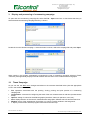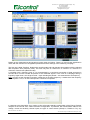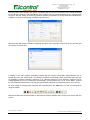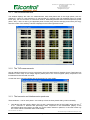
1
Via Vizzano, 44 - 40044 Pontecchio Marconi (BO) – Italy
Tel. +39 051 6782006
Fax +39 051 845544
http://www.elcontrol-energy.net
[email protected]
PE Studio
User’s Manual – Rel. PES-0.2
Power Energy analysis software in Windows environment
for the Energy Explorer professional analyser
Rel. User’s Manual – Rel. PES-0.2
This manual is subject to modifications without prior notice.
Page 1 of 32
Via Vizzano, 44 - 40044 Pontecchio Marconi (BO) – Italy
Tel. +39 051 6782006
Fax +39 051 845544
http://www.elcontrol-energy.net
[email protected]
Rel. User’s Manual – Rel. PES-0.2
This manual is subject to modifications without prior notice.
Page 2 of 32
Via Vizzano, 44 - 40044 Pontecchio Marconi (BO) – Italy
Tel. +39 051 6782006
Fax +39 051 845544
http://www.elcontrol-energy.net
[email protected]
PE Studio
Power Energy analysis software in Windows environment
for the Energy Explorer professional analyser
Table of Contents
1
GENERAL DESCRIPTION ........................................................................................................................ 4
1.1
1.2
2
THE MEASURING CAMPAIGNS .............................................................................................................. 6
2.1
2.2
3
THE MAIN WINDOW ................................................................................................................................. 4
THE MAIN MENU ..................................................................................................................................... 5
PRELIMINARY NOTES.............................................................................................................................. 6
ORGANISATION OF THE MEASURING CAMPAIGNS ON THE CF .................................................................... 6
DISPLAY AND PROCESSING OF A MEASURING CAMPAIGN ............................................................ 8
3.1
TIMED CAMPAIGN .................................................................................................................................. 8
3.1.1 The rms measurements................................................................................................................. 11
3.1.2 The THD measurements ............................................................................................................... 11
3.1.3 The harmonic and interharmonic spectrums ................................................................................. 11
3.1.4 The voltage and current waveforms .............................................................................................. 13
3.1.5 The time trend of the rms measurements ..................................................................................... 16
3.1.5.1
3.1.5.2
3.1.5.3
Recorder toolbar.................................................................................................................................... 16
Setting the number of tracks and the parameter associated with a track .............................................. 17
Indicators of the current record and random record search................................................................... 18
3.1.6 Grid with rms measurements in Excel style .................................................................................. 18
3.1.6.1
3.1.6.2
Making a graph of a set of measurements ............................................................................................ 19
Exporting a set of measurements.......................................................................................................... 20
3.1.7 The vector meter ........................................................................................................................... 20
3.1.8 Exporting the measurements into a text file .................................................................................. 21
3.2
RMS CAMPAIGN ................................................................................................................................... 22
3.2.1 The rms measurements................................................................................................................. 23
3.2.2 The THD measurements ............................................................................................................... 23
3.2.3 The vector meter ........................................................................................................................... 23
3.2.4 Grid with rms measurements in Excel style .................................................................................. 23
4
CUSTOMISING THE GRAPH COLOURS............................................................................................... 23
5
PRINTING DOCUMENTS ........................................................................................................................ 25
5.1
5.2
5.3
5.4
5.5
5.6
6
INFORMATION ABOUT THE MEASURING CAMPAIGN .................................................................................. 26
GRID WITH RMS MEASUREMENTS IN EXCEL STYLE ................................................................................. 27
THE HARMONIC SPECTRUM................................................................................................................... 28
THE VOLTAGE AND CURRENT WAVEFORMS ............................................................................................ 29
THE TIME TREND OF THE RMS MEASUREMENTS ...................................................................................... 30
THE VECTOR METER ............................................................................................................................ 31
SYSTEM REQUIREMENTS..................................................................................................................... 32
Rel. User’s Manual – Rel. PES-0.2
This manual is subject to modifications without prior notice.
Page 3 of 32
Via Vizzano, 44 - 40044 Pontecchio Marconi (BO) – Italy
Tel. +39 051 6782006
Fax +39 051 845544
http://www.elcontrol-energy.net
[email protected]
PE Studio
Power Energy analysis software in Windows environment
for the Energy Explorer professional analyser
1
General description
PE Studio is a software application in Windows environment that lets you process the data recorded by the
Energy Explorer professional analyser of electrical energy. PE Studio is able to repeat all analyses
performed by Energy Explorer on the system. It therefore lets you reconstruct waveforms, energy data and
the events that occurred during the measuring campaign.
Energy Explorer saves the measuring campaigns on a Compact Flash (CF) type of memory. The data stored
in it can later be transferred onto the PC for analysis, creating and printing reports, filing and other important
functions.
The program envisages only the OFF-Line operating mode, i.e. it does not interact by communicating with
the instrument. In order to transfer the measuring campaigns, you have to first remove the memory from
Energy Explorer (always remembering to turn off the instrument beforehand). By using a proper external CF
memory reader or a PCMCIA adaptor, data can be copied onto the hard disk using the Copy – Paste
function of Windows Explorer. It is also feasible to open the files directly from the CF. The organisation and
types of measuring campaigns will be looked at in detail farther on.
It is possible to analyse two or more campaigns at the same time. The only limitation is the PC’s computing
power, available memory and disk space.
The default language can be selected in real time by changing the international settings for the numbers,
currency, date and time, etc. The program configures itself with the local international settings with the first
execution.
1.1
The main window
The application presents the following first window:
Rel. User’s Manual – Rel. PES-0.2
This manual is subject to modifications without prior notice.
Page 4 of 32
Via Vizzano, 44 - 40044 Pontecchio Marconi (BO) – Italy
Tel. +39 051 6782006
Fax +39 051 845544
http://www.elcontrol-energy.net
[email protected]
It is made up of a title, main menu, and toolbars (for quickly accessing the application’s most important
functions). There is also a work area where the different windows with the instrument’s measurements,
graphs, etc. are displayed, etc., and a status bar with the system clock.
1.2
•
•
•
•
The main menu
File: operations associated with the opening, printing and print preview of a measuring campaign file.
Options: setting the default language.
View: display selection of the different tool bars and status bar.
?: display of the window with the program information and online help.
A series of icons depicting the tool bars are underneath the main menu. They are divided into five types:
main, view control, measurement trend control (recorder function), record position, harmonic spectrum mode.
The user can freely enable/disable their display using the View command of the main menu. It is also
possible to customise the position of each bar by proceeding as follows: with the mouse, point in the area
adjacent to a toolbar’s buttons and move the cursor with the left mouse button pressed. The selected toolbar
disengages from its original position and is dragged along with the cursor’s movements; the toolbar is drawn
in the new position when the left mouse button is released. The toolbar can be left fluctuating in a given point
of the screen, or can be once again hooked on to any one of the four borders of the main window.
Rel. User’s Manual – Rel. PES-0.2
This manual is subject to modifications without prior notice.
Page 5 of 32
Via Vizzano, 44 - 40044 Pontecchio Marconi (BO) – Italy
Tel. +39 051 6782006
Fax +39 051 845544
http://www.elcontrol-energy.net
[email protected]
2
The measuring campaigns
2.1
Preliminary notes
As previously mentioned, Energy Explorer allows various pieces of information that characterise the
electrical phenomena to be stored in the measuring campaigns.
The measuring campaigns can be carried out in two different modes:
•
•
Manual: the user manually decides when to start and stop data acquisition;
Automatic: the user configures one or more campaigns in a list of campaigns. The automatic campaign
manager continuously controls the status of the above-mentioned list, automatically executing the
campaigns it contains;
In turn, there are three very distinct types of campaigns:
•
•
Timed: the records with the information about the samples of the voltage and current input signals are
saved in regular time intervals, from a minimum of 5 sec to a maximum of 1 hour (3600 seconds)
Rms: the records with the rms values of all measures are saved in regular time intervals, from a
minimum of 0 (continuous flow of data) to a maximum of 1 hour (3600 seconds).
2.2
Organisation of the measuring campaigns on the CF
Every measuring campaign is stored according to a common procedure: there is a directory in the Compact
Flash root directory that acts as a container of all the campaigns, and is called Survey. At this level – and for
every new measuring campaign – a directory is created; its name will have this type of form:
YYYYMMDD-NNN-AAAA…A
where
•
•
•
•
•
YYYY = year
MM = month
DD = day
NNN = progressive campaign number from 000 to 999, it serves to identify the same type of campaigns
over the same day
AAAA…A = user-defined descriptive label
A campaign is made up of:
An .srve file, which is the actual campaign file where the parameters characterising it are saved. This is the
document file for the program. It is a very small file, and its file name is the same as the directory containing
it.
One or more .XXXX files (where XXXX is a number from 0000 to 9999), where the records with the
measurements or samples of the waveforms are saved. Depending on the set acquisition frequency, these
files may reach dimensions of about one megabyte.
Rel. User’s Manual – Rel. PES-0.2
This manual is subject to modifications without prior notice.
Page 6 of 32
Via Vizzano, 44 - 40044 Pontecchio Marconi (BO) – Italy
Tel. +39 051 6782006
Fax +39 051 845544
http://www.elcontrol-energy.net
[email protected]
For example, let us suppose that the Compact Flash memory has been recognised by the operating system
as a new unit with the letter F, then the structure of the files will be as follows:
F:
|
--Survey
|
+--20050406-000-Manual Campaign
| |
| |--20050406-000-Manual Campaign.srve
| |--20050406-000-Manual Campaign.0000
| |--20050407-000-Manual Campaign.0001
|
--20050408-000-Manual Campaign.0002
|
+--20050409-000-Manual Campaign
| |
| |--20050409-000-Manual Campaign.srve
| |--20050409-000-Manual Campaign.0000
|
--20050410-000-Manual Campaign.0001
|
+--20050110-000-Automatic Campaign
| |
| |--20050110-000-Automatic Campaign.srve
| |--20050110-000-Automatic Campaign.0000
| |--20050111-000-Automatic Campaign.0001
| |--20050112-000-Automatic Campaign.0002
|
--20050113-000-Automatic Campaign.0003
|
.
.
.
At this point a small clarification becomes necessary. Up until now it has been said – in an entirely general
way – that a measuring campaign is a set of binary data organised in records. As is easy to imagine, what is
contained will depend on the nature of the campaign. A record is made up of the samples for each input
signal (3 under voltage and 4 under current) for a total of 60 signal periods, which at the frequency of 50 Hz
are equivalent to 1.2 seconds of recording, or 1 second at 60 Hz.
It is now important to establish that the entire PE Studio application is broken down into measurement
records. The movements within the recording, the graphs, calculations and everything else are based on
these packets of information.
Rel. User’s Manual – Rel. PES-0.2
This manual is subject to modifications without prior notice.
Page 7 of 32
Via Vizzano, 44 - 40044 Pontecchio Marconi (BO) – Italy
Tel. +39 051 6782006
Fax +39 051 845544
http://www.elcontrol-energy.net
[email protected]
3
Display and processing of a measuring campaign
To open and view a measuring campaign file, select the File – Open menu item. A first window that lets you
select the desired measuring campaign directory is shown:
Double-click on the desired campaign. A second window is shown; select the campaign file and press Open:
When opening, the program automatically recognises the type of measuring campaign selected (Timed,
Transient ) and opportunely displays several windows with the views of the measurements and graphs.
3.1
Timed Campaign
As you can see, the Main menu changes and takes on the structure described below (also the appropriate
icons in the toolbars are enabled):
•
•
•
•
•
•
File: operations associated with the opening, closing, printing and print preview of a measuring
campaign file.
Configuration: command for configuring the trend of the rms measurements in real time (measurements
trend).
Options: setting of colours for the different graphs (waveform, harmonic spectrum, trend, etc.).
View: display selection of the numeric measurements and graphs, different tool bars and the status bar.
Window: set-up of the arrangement of windows or to call up a certain window in the foreground.
?: display of the window with the program information and online help.
Rel. User’s Manual – Rel. PES-0.2
This manual is subject to modifications without prior notice.
Page 8 of 32
Via Vizzano, 44 - 40044 Pontecchio Marconi (BO) – Italy
Tel. +39 051 6782006
Fax +39 051 845544
http://www.elcontrol-energy.net
[email protected]
Display of the measurements and graphs is broken down as follows. There is a main window organised in
cards, with the instrument’s configuration parameters and the settings of the measuring campaign.
The first card, called Timelines, displays the recording start and end date and time together with the relevant
data acquisition time (frequency time). This time may take on values from a minimum of 0 second to a
maximum of 60 minutes (3600 seconds).
A campaign with a frequency time of 0 is characterised by a continuous succession of data structured in
records, each of which includes 60 periods of the measured signals. In the case of a campaign having a
frequency higher than 0, the single records – again including 60 periods – are saved with the set frequency.
Note: as every record includes 60 periods, irrespective of the basic frequency; it results that if the frequency
time is equal to 1 sec, it as well corresponds to continuous acquisition.
In returning to the description of our cards, we find a first part regarding configuration of the Energy Explorer
analyser in the second card, called Instrument Configuration. In particular, the transformation ratios of the
voltage, current and auxiliary channel inputs, the type of current sensor (Clamp-on, Flexible or TA), any
Rel. User’s Manual – Rel. PES-0.2
This manual is subject to modifications without prior notice.
Page 9 of 32
Via Vizzano, 44 - 40044 Pontecchio Marconi (BO) – Italy
Tel. +39 051 6782006
Fax +39 051 845544
http://www.elcontrol-energy.net
[email protected]
reversal of the current sensors, the type of connection (with two, three or four wires), the nominal frequency
for the harmonic analysis, and the enabling of the auxiliary input and scale extended for the voltage inputs
are given. Also the version of the Energy Explorer firmware is indicated. All of this information illustrates the
conditions in which the measuring campaign was performed.
The Main card offers other information regarding the name of the campaign, user notes (if any) and the type
of recording: Timed or Rms
In addition to the main window, secondary windows with the numeric and graphic measurements can be
viewed when the user selects them. The following views are automatically shown by default when this type
of campaign is opened: Harmonic Spectrum V1-I1, Harmonic Spectrum V2-I2, Harmonic Spectrum V2-I2,
Voltage Waveforms V1-V2-V3 referring to neutral (Star), Current Waveforms I1-I2-I3, Vector Meter, Trend of
the rms measurements and an Excel style grid (whose lines represent the measurements for each record).
All views useful for analysing the campaign are accessible from the View menu, or even more directly by
using the toolbar
Note that a label with short description of the button pointed at appears when moving over the bar with the
mouse.
Rel. User’s Manual – Rel. PES-0.2
This manual is subject to modifications without prior notice.
Page 10 of 32
Via Vizzano, 44 - 40044 Pontecchio Marconi (BO) – Italy
Tel. +39 051 6782006
Fax +39 051 845544
http://www.elcontrol-energy.net
[email protected]
3.1.1 The rms measurements
This window displays the main rms measurements, both three-phase and of the single phase, such as:
voltage (V), current (I), cosø, frequency (f), active power (P), reactive power (Q), apparent power (S), power
factor (PF), the four counters of active and reactive, absorbed/generated and inductive/capacitive power
(Whabs, Whgen, varhind e varhcap), the apparent power counter (Vah), and the average power factor (PF avrg).
Also the current of the auxiliary channel is displayed in the lower right-hand corner.
3.1.2 The THD measurements
We can identify three boxes, one for each phase, giving the total harmonic distortion factor (Total Harmonic
Distortion Factor THD) of the voltage signals (THDV) and of the current signals (THDI) compared to the
fundamental and to the total rms value.
Consult the user’s manual supplied with the instrument for more details.
3.1.3 The harmonic and interharmonic spectrums
These windows – one for each phase – are made up of two sections placed side by side horizontally:
•
One section with the numeric display of the V and I measurements and of the Cosphi value from the 1st
to 31st harmonic in absolute and percentage value compared to the fundamental (display of the
percentage values and Cosphi are valid only for the classic harmonic spectrum, in the other cases only
the V and I values in absolute value will be listed);
Rel. User’s Manual – Rel. PES-0.2
This manual is subject to modifications without prior notice.
Page 11 of 32
Via Vizzano, 44 - 40044 Pontecchio Marconi (BO) – Italy
Tel. +39 051 6782006
Fax +39 051 845544
http://www.elcontrol-energy.net
[email protected]
•
One section with the graphic display of the V and I harmonic spectrum in percentage value compared to
the fundamental.
You can alter the size of the above-mentioned areas by dragging the vertical separation bar between the two
sections with the mouse.
You can sort the measurements by value (from lesser to greater) by pressing on the buttons of the title of a
given column in the left section. By default they are sorted by number of harmonic order (first column on the
left).
When positioning the cursor on the graphs, the Point and Measure function is enabled: if the cursor is left for
more than 2 seconds on a certain point of the graphs, a small indicator with the measurement expressed in
the units of measure indicated on the vertical and horizontal axes of the system of reference in that point is
automatically displayed. In our case it will be the percentage value of the harmonic component and the
number of harmonic order with the relevant equivalent frequency.
It is possible to change the display mode of the spectrum and of the relevant measurements using the
toolbar
- you choose between harmonic and interharmonic spectrum with the
first 6 buttons, whereas you change between linear scale or logarithmic scale (only for the axis of the
ordinates) with the last button on the right (shown with a yellow grid). Some examples:
harmonic spectrum
Rel. User’s Manual – Rel. PES-0.2
This manual is subject to modifications without prior notice.
Page 12 of 32
Via Vizzano, 44 - 40044 Pontecchio Marconi (BO) – Italy
Tel. +39 051 6782006
Fax +39 051 845544
http://www.elcontrol-energy.net
[email protected]
The last two figures display the detailed harmonic spectrum. The coloured bars depict the classic harmonics,
whereas the grey bars depict the interharmonics. The frequency for each harmonic order is the multiple of
the fundamental frequency; for example, we will have 1st ord.=50Hz, 2nd ord.=100 Hz, 3rd ord.=150Hz and so
on for a 50Hz frequency. Similarly, it will be 1st ord.=60Hz, 2nd ord.=120Hz, 3rd ord.=180Hz, etc. for a 60Hz
frequency. The interharmonic values, on the other hand, increase in 5Hz steps for a fundamental frequency
of 50Hz and in 6Hz steps for a 60Hz fundamental frequency.
If the logarithmic scale is applied (exemplified here in the complete spectrum, but just as valid for any one of
the other graphs), we quickly get a magnification of the lowest percentage values. Note how in one case it is
at 50%, at half scale, whereas in the other case it is at 10%.
3.1.4 The voltage and current waveforms
Here we have a complete series of views that allow us to observe the waveforms for all of the voltage and
current inputs in different combinations in detail. We’ll start off explaining the operation by taking a single
window as an example. The same concepts are however applicable to all the other windows of this type. A
waveform view is nothing other than a small oscilloscope. The control panel is shown on the left side, and on
the right are the actual oscillograms. How many and which signals will be displayed will depend on the type
of view selected. There are 7 different combinations: V1-V2-V3 star, V1-V2-V3 delta, I1-I2-I3, V1-I1, V2-I2,
V3-I3 and I4 (auxiliary channel).
The control panel is made up like this: three switches for changing the gain or
amplitude for each channel, a common switch for changing the time base, a
scroll bar for positioning the display area or window inside the record
(remember that a record is equivalent to 60 periods of the fundamental
frequency) and a switch for combining all the channels in a single grid. In this
case, it will be necessary to select the corresponding channel in order to be
able to use the Point and Measure function on a track.
Rel. User’s Manual – Rel. PES-0.2
This manual is subject to modifications without prior notice.
Page 13 of 32
Via Vizzano, 44 - 40044 Pontecchio Marconi (BO) – Italy
Tel. +39 051 6782006
Fax +39 051 845544
http://www.elcontrol-energy.net
[email protected]
When positioning the cursor on the graphs, the Point and Measure function is enabled: if the cursor is left for
more than 2 seconds on a certain point of the graphs, a small indicator with the measurement expressed in
the units of measure indicated on the vertical and horizontal axes of the system of reference in that point is
automatically displayed. In our case the Volts or Amperes and the number of milliseconds will be measured
starting from the beginning of the buffer.
Just use the Time base switch to increase or
decrease resolution by time units.
All of the channels are grouped together in a
single grid when you click on the Single grid
control.
Rel. User’s Manual – Rel. PES-0.2
This manual is subject to modifications without prior notice.
Page 14 of 32
Via Vizzano, 44 - 40044 Pontecchio Marconi (BO) – Italy
Tel. +39 051 6782006
Fax +39 051 845544
http://www.elcontrol-energy.net
[email protected]
Just set the CH1, CH2 or CH3 switches to
increase or decrease the amplitudes of the
signals.
Changing the position of the display interval to
another point of the record is simple with the
Window position scroll bar. This option is useful
for searching for particular events.
Rel. User’s Manual – Rel. PES-0.2
This manual is subject to modifications without prior notice.
Page 15 of 32
Via Vizzano, 44 - 40044 Pontecchio Marconi (BO) – Italy
Tel. +39 051 6782006
Fax +39 051 845544
http://www.elcontrol-energy.net
[email protected]
3.1.5 The time trend of the rms measurements
You can enable a function called trend for the rms values that lets you plot their trend over time. The figure
below represents the default window with the trends of 4 channels: voltage (V), current (I), active power (P)
and the three-phase power factor (PF).
In this case the scale factor for the ordinates is automatic, and it keeps the signal always at the maximum
resolution (80% of the full scale). As for the x-axis, the following consideration applies: it is fixed and
corresponds to 60 samplings expressed in the measuring campaign frequency time. When the frequency
time is equal to 0, a value equivalent to 1 second is forced, so the time display window will be 60 x 1 = 60
seconds (1 minute). If, for example, the frequency time were to be 5 minutes, the interval would be
equivalent to 60 x 5 = 300 minutes (5 hours).
When the last plotted value exceeds 95% of the display time interval, the tracks are moved to the left,
deleting the oldest data, so the displayed data always correspond to the last 60 x sampling time seconds.
When positioning the cursor on the graphs, the Point and Measure function is enabled: if the cursor is left for
more than 2 seconds on a certain point of the graphs, a small indicator with the measurement expressed in
the units of measure indicated on the vertical and horizontal axes of the system of reference in that point is
automatically displayed.
3.1.5.1
Recorder toolbar
Rel. User’s Manual – Rel. PES-0.2
This manual is subject to modifications without prior notice.
Page 16 of 32
Via Vizzano, 44 - 40044 Pontecchio Marconi (BO) – Italy
Tel. +39 051 6782006
Fax +39 051 845544
http://www.elcontrol-energy.net
[email protected]
When the measurements trend window is displayed during a campaign, the recorder function is enabled. It
lets you make the measuring campaign scroll by, creating an animation as if it were a measurement in real
time.
It is possible to move to the beginning or end of the recording, and perform a normal or fast forward or
rewind. You can momentarily stop execution during reproduction by pressing the pause button.
Press the pause button again to resume execution of the measurements trend.
If there are other secondary views displayed together with the measurements trend, they will be coupled with
the recorder function, i.e. if the trend is paused, so will the other views. When the pause function is enabled,
the secondary views display the first record in the display interval of the measurements trend.
3.1.5.2
Setting the number of tracks and the parameter associated with a track
You can customise the number of tracks (or channels) displayed in the trends window and the parameter
associated with each track using menu item Configuration – Trend:
The number of tracks displayed may vary from a minimum of 1 up to a maximum of 4. Select the box Enable
to enable/disable a channel. To change the parameter associated with a channel, select it in the box
regarding the desired channel. The possible parameters are:
•
•
•
•
•
•
•
•
•
•
•
•
•
V
I
P
PF
Q
S
f
Whabs
Whgen
varhind
varhcap
Q Peak
S Peak
•
•
•
•
•
•
•
•
•
•
•
•
•
P Peak
V (L1)
V (L2)
V (L3)
I (L1)
I (L2)
I (L3)
P (L1)
P (L2)
P (L3)
PF (L1)
PF (L2)
PF (L3)
•
•
•
•
•
•
•
•
•
•
•
•
•
Q (L1)
Q (L2)
Q (L3)
S (L1)
S (L2)
S (L3)
Avrg. Q
Avrg. S
Avrg. P
Thd ref. V fnd (L1)
Thd ref. V rms (L1)
Thd ref. I fnd (L1)
Thd ref. I rms (L1)
Rel. User’s Manual – Rel. PES-0.2
This manual is subject to modifications without prior notice.
Page 17 of 32
Via Vizzano, 44 - 40044 Pontecchio Marconi (BO) – Italy
Tel. +39 051 6782006
Fax +39 051 845544
http://www.elcontrol-energy.net
[email protected]
•
•
•
•
•
•
•
•
Thd ref. V fnd (L2)
Thd ref. V rms (L2)
Thd ref. I fnd (L2)
Thd ref. I rms (L2)
Thd ref. V fnd (L3)
Thd ref. V rms (L3)
Thd ref. I fnd (L3)
Thd ref. I rms (L3)
•
•
•
•
•
•
•
•
Harm V (L1)
Harm V% of fnd (L1)
Harm I (L1)
Harm I% of fnd (L1)
Harm Cosphi (L1)
Harm V (L2)
Harm V% of fnd (L2)
Harm I (L2)
•
•
•
•
•
•
•
Harm I% of fnd (L2)
Harm Cosphi (L2)
Harm V (L3)
Harm V% of fnd (L3)
Harm I (L3)
Harm I% of fnd (L3)
Harm Cosphi (L3)
Note: when you select a harmonic measurement of V, I or the Cosphi value, you have to specify the
harmonic order in the relevant input box.
The changes made are permanent, meaning that the program saves them in the configuration register so as
to be able to restore them in the future in another work session.
3.1.5.3
Indicators of the current record and random record search
Right under the main menu is a small window indicating the number, date and time of the record currently
displayed in the measurements and graphs windows.
While there is a reproduction in progress, the indicators are continuously updated with the information
concerning the current record. If the campaign is momentarily put in pause status, the window keeps the last
values displayed.
On the other hand, the indicators stay empty when just the measurements are displayed unless you enter
the pause status and use the recorder function.
You can position yourself on any point of the measuring campaign with the Find Record function. When you
press the button located to the left of the indicators, a window like this one is displayed:
Set the date and time of the desired record and press OK. Positioning is also possible based on the
corresponding number of the record. To do this, select the box Find by record no., enter the desired record
number and press OK. Now all of the windows with the displayed measurements and graphs will be updated
to the set record.
Lastly, there is a scroll control on the right for quick moves.
3.1.6 Grid with rms measurements in Excel style
By selecting menu item View – Records, a window containing a grid in Excel style is displayed. Its lines
represent the campaign’s records in chronological order, whereas every column contains the rms value of
the parameter shown in the first line.
Rel. User’s Manual – Rel. PES-0.2
This manual is subject to modifications without prior notice.
Page 18 of 32
Via Vizzano, 44 - 40044 Pontecchio Marconi (BO) – Italy
Tel. +39 051 6782006
Fax +39 051 845544
http://www.elcontrol-energy.net
[email protected]
3.1.6.1
Making a graph of a set of measurements
You can select from one to four parameters (columns) for a maximum of 5000 records with the mouse; then
the measurements selected will be graphically represented in just as many oscilloscope type of quadrants
contained in a new window when you select the option Make rms graph from the contextual Selection
menu. In this context it is possible to change the way of plotting the measurements: from histogram to trend
and vice versa. If the number of selected records is greater than the quadrant’s graphic capability, you can
actuate scrolling of the parameters shown in both directions using the buttons found in the lower left-hand
corner (< and >).
Moreover, this window shows fields that give, respectively:
•
•
•
the date of the records currently depicted in the oscillogram;
the total number of selected records;
the recording frequency of the records (Frequency).
Rel. User’s Manual – Rel. PES-0.2
This manual is subject to modifications without prior notice.
Page 19 of 32
Via Vizzano, 44 - 40044 Pontecchio Marconi (BO) – Italy
Tel. +39 051 6782006
Fax +39 051 845544
http://www.elcontrol-energy.net
[email protected]
The recording times of the first and last record currently shown on the graph are shown at the ends of the
quadrant’s abscissa. When positioning the cursor on the graphs, the Point and Measure function is enabled:
if the cursor is left for more than 2 seconds on a certain point of the graphs, a small indicator with the
measurement expressed in the units of measure indicated on the vertical and horizontal axes of the system
of reference in that point is automatically displayed.
3.1.6.2
Exporting a set of measurements
To export data, select the records to be exported with the mouse, press the right mouse button and then
select the option Export… from the contextual Selection menu. The records in the selected range will be
automatically exported while displaying a window of this type:
For more details, consult the paragraph 3.1.8.
3.1.7 The vector meter
The fundamental parameters of the voltages (between phase and neutral) and of the currents are depicted
on this page in vector mode, i. e. in module and phase. The panel on the right side of the graph lists the
voltages and currents with the respective modules and phase angles, and farther down the cosine of the
phase angle between V1-I1, V2-I2 and V3-I3 with the relevant indication of the type of load: inductive or
capacitive. Lastly, the unbalance of the three-phase voltage system expressed in a percentage is displayed.
Values close to 0% indicate a balanced system.
Rel. User’s Manual – Rel. PES-0.2
This manual is subject to modifications without prior notice.
Page 20 of 32
Via Vizzano, 44 - 40044 Pontecchio Marconi (BO) – Italy
Tel. +39 051 6782006
Fax +39 051 845544
http://www.elcontrol-energy.net
[email protected]
3.1.8 Exporting the measurements into a text file
You can export the data recorded in a measuring campaign into a text file, which can later be imported by
other data processing programs like Excel, for example.
Select menu item File – Export to start the export. A window where you can set the export mode (part or all
of the measuring campaign) and the export interval expressed in number of records is displayed.
To export the entire campaign, select All and press Export. If, on the other hand, you want to export just a
part, select Interval, set the first record number (in the box From:) and last record number (in the box To:),
and then press Export. Tip: use the grid view of the measurements in Excel style (View – Records) to
identify the number of the records of the desired export interval.
Progress is displayed during export, and the Export button becomes Stop. The operation may even last a
few minutes, depending on the type of campaign and its duration. You may however stop its process at any
time by pressing the Stop button.
The export files are created in the directory indicated in the relevant input box. The directory where the
measuring campaign resides is presented by default. The export files are divided into four types and can be
distinguished based on their file extensions:
•
•
•
•
.MXXX: file with the same rms measurements contained in the Excel style of grid. XXX is a progressive
number from 000 to 999, and is used in subdividing a very long campaign;
.AXXX: file with the measurements of V and I and of the Cosphi value from the 1st to the 31st harmonic
for each phase in absolute value. XXX is a progressive number from 000 to 999, and is used in
subdividing a very long campaign;
.PXXX: file with the measurements of V and I and of the Cosphi value from the 1st to the 31st harmonic
for each phase in percentage value. XXX is a progressive number from 000 to 999, and is used in
subdividing a very long campaign;
.WXXX: file with the samples of the waveforms of V and I for each phase. XXX is a progressive number
from 000 to 999, and is used in subdividing a very long campaign.
The character used as the field separator is Tab (ASCII code 09).
Rel. User’s Manual – Rel. PES-0.2
This manual is subject to modifications without prior notice.
Page 21 of 32
Via Vizzano, 44 - 40044 Pontecchio Marconi (BO) – Italy
Tel. +39 051 6782006
Fax +39 051 845544
http://www.elcontrol-energy.net
[email protected]
For the first three files, every line corresponds to a record of the measuring campaign, whereas every
column contains the amplitude measurement value indicated in the first line. On the other hand, every record
is saved on six lines for the file with export of the samples: the first three correspond to the voltages (V1, V2
and V3), and the second three to the currents (I1, I2 and I3). Owing to the nature of this export, the resulting
file may come large in size. It is therefore recommended to make several partial exports.
3.2
Rms Campaign
As you can see, the campaign configuration window as well as the other graphic views are perfectly similar
to those already described for the Timed type of campaign.
The differences are minimum and regard a supplementary view with the list of overvoltage and overcurrent
events detected during analysis of the system. Moreover, some broken lines (one vertical and two horizontal)
have been added in the oscillograms. They depict the instant and the minimum and maximum trigger
thresholds, meant as a symmetrical peak value compared to the neutral.
The View menu and the toolbar now change appearance, adapting themselves to this type of campaign: the
spectrum analysis, trend and vector meter are no longer available. A new button tied to the window with the
list of the events previously mentioned is however enabled.
In going back to the configuration window, the peak value set as the trigger threshold is given in the
Transients card together with the trigger sources for the voltages and currents.
Rel. User’s Manual – Rel. PES-0.2
This manual is subject to modifications without prior notice.
Page 22 of 32
Via Vizzano, 44 - 40044 Pontecchio Marconi (BO) – Italy
Tel. +39 051 6782006
Fax +39 051 845544
http://www.elcontrol-energy.net
[email protected]
3.2.1 The rms measurements
See paragraph 3.1.1.
3.2.2 The THD measurements
See paragraph 3.1.2.
3.2.3 The vector meter
See paragraph 3.1.7.
3.2.4 Grid with rms measurements in Excel style
See paragraph 3.1.6.
4
Customising the graph colours
If you want to change the default setting of the graph colours, click on any point of the graph with the right
mouse button or select the menu item Options – Colours. A window that lets you freely select the colours of
the different areas of the oscillogram appears, such as: panel colour, track colour, pen colour, etc. Note: the
same number of tracks of the graph that you are configuring is given on the colour configuration window.
Depending on the case at hand, it may be a number from 1 to 4.
•
•
Select the channel you want to configure by pressing the button CH1, CH2, CH3 or CH4.
Select the area whose colour you want to change by pressing one of the buttons found in the Colour
selection group. A window like this appears:
Rel. User’s Manual – Rel. PES-0.2
This manual is subject to modifications without prior notice.
Page 23 of 32
Via Vizzano, 44 - 40044 Pontecchio Marconi (BO) – Italy
Tel. +39 051 6782006
Fax +39 051 845544
http://www.elcontrol-energy.net
[email protected]
•
•
•
Select the desired colour and press OK.
Repeat the preceding steps for the other areas to be modified.
Lastly, press the OK button in the configuration window of the graph colours. The changes made will be
shown on the original graph.
Rel. User’s Manual – Rel. PES-0.2
This manual is subject to modifications without prior notice.
Page 24 of 32
Via Vizzano, 44 - 40044 Pontecchio Marconi (BO) – Italy
Tel. +39 051 6782006
Fax +39 051 845544
http://www.elcontrol-energy.net
[email protected]
5
Printing documents
The program lets you print all of the measurements and previously illustrated graphs on both black and white
and colour printers for paper filing and for filling in system analysis reports.
You can print with the paper in either portrait or landscape orientation, without distinction. It is also possible
to get a print preview on the screen for all prints before actually printing. The printer management criterion is
the Windows environment standard.
The print preview and print refer to the currently selected window, i.e. the one in the foreground
characterised by the active title bar. So before printing, click on the desired window or select it using the
Window command of the main menu.
A few print examples are shown below:
Rel. User’s Manual – Rel. PES-0.2
This manual is subject to modifications without prior notice.
Page 25 of 32
Via Vizzano, 44 - 40044 Pontecchio Marconi (BO) – Italy
Tel. +39 051 6782006
Fax +39 051 845544
http://www.elcontrol-energy.net
[email protected]
5.1
Information about the measuring campaign
Rel. User’s Manual – Rel. PES-0.2
This manual is subject to modifications without prior notice.
Page 26 of 32
Via Vizzano, 44 - 40044 Pontecchio Marconi (BO) – Italy
Tel. +39 051 6782006
Fax +39 051 845544
http://www.elcontrol-energy.net
[email protected]
5.2
Grid with rms measurements in Excel style
Rel. User’s Manual – Rel. PES-0.2
This manual is subject to modifications without prior notice.
Page 27 of 32
Via Vizzano, 44 - 40044 Pontecchio Marconi (BO) – Italy
Tel. +39 051 6782006
Fax +39 051 845544
http://www.elcontrol-energy.net
[email protected]
5.3
The harmonic spectrum
Rel. User’s Manual – Rel. PES-0.2
This manual is subject to modifications without prior notice.
Page 28 of 32
Via Vizzano, 44 - 40044 Pontecchio Marconi (BO) – Italy
Tel. +39 051 6782006
Fax +39 051 845544
http://www.elcontrol-energy.net
[email protected]
5.4
The voltage and current waveforms
Rel. User’s Manual – Rel. PES-0.2
This manual is subject to modifications without prior notice.
Page 29 of 32
Via Vizzano, 44 - 40044 Pontecchio Marconi (BO) – Italy
Tel. +39 051 6782006
Fax +39 051 845544
http://www.elcontrol-energy.net
[email protected]
5.5
The time trend of the rms measurements
Rel. User’s Manual – Rel. PES-0.2
This manual is subject to modifications without prior notice.
Page 30 of 32
Via Vizzano, 44 - 40044 Pontecchio Marconi (BO) – Italy
Tel. +39 051 6782006
Fax +39 051 845544
http://www.elcontrol-energy.net
[email protected]
5.6
The vector meter
Rel. User’s Manual – Rel. PES-0.2
This manual is subject to modifications without prior notice.
Page 31 of 32
Via Vizzano, 44 - 40044 Pontecchio Marconi (BO) – Italy
Tel. +39 051 6782006
Fax +39 051 845544
http://www.elcontrol-energy.net
[email protected]
6
•
•
•
•
•
•
•
•
System requirements
PC compatible with 600MHz or higher processor;
Microsoft Windows 9x, Se, Me, NT 4.0, 2000 or XP;
128 MB of RAM memory (512 recommended);
SVGA with 256 colours 1024x768 or higher resolution;
512 MB of free hard disk space, including program installation and the free space necessary for storing a
minimum number of measuring campaigns;
CD/DVD-ROM drive;
CF reader (external, internal or PCMCIA)
Pointing system or mouse.
Note: all of the names are registered trademarks of the respective manufacturers.
Rel. User’s Manual – Rel. PES-0.2
This manual is subject to modifications without prior notice.
Page 32 of 32