1
SR23 Series
Digital Controller
Instruction Manual
1-input
Thank you for purchasing the Shimaden SR23 Series Digital
Controller. Check that the delivered product is the correct item you
ordered. Do not begin operating this product until you have read
and thoroughly understood the contents of this Instruction Manual.
SHIMADEN CO., LTD.
MSR023-E01-B
Jan, 2006
i
Request
Make sure that this Instruction Manual is given to the final user of the device.
Keep this manual at the work site during operation of the SR23 Series.
Preface
This Instruction Manual describes the basic functions and how to use "1-input: 1output/2-output" SR23 Series Controllers. For details on "2-input: 1-output/2output" and "servo output," refer to separate manuals.
This Instruction Manual is meant for those will be involved in the wiring,
installation, operation and routine maintenance of the SR23 Series. This manual
describes the handling, installation and wiring procedures for operation.
While using this device, you should always follow the instructions written in this
manual.
For safety precautions and potential damage to equipment and/or facilities,
additional instructions are indicated by the following headings.
Safety Precautions
Warning
The SR23 Series Digital Controller is designed for controlling
temperature, humidity and other physical quantities in general industrial
facilities. It must not be used in any way that may adversely affect the
safety, health or working conditions of those who come into contact with
the effects of its use. When used, adequate and effective safety
countermeasures must be provided at all times by the user. No warranty,
express or implied, is valid when this device is used without the proper
safety countermeasures.
Warning
Before you start to use this device, install it in a control panel or the
like and avoid touching the terminals.
Do not open this device's case, and touch the boards or inside of the
case with your hands or a conductor. The user should never repair or
modify this device. Doing so might cause an accident that may result
in death or serious bodily injury from electric shock.
ii
Caution
To avoid damage to connected peripheral devices, facilities or the product
itself due to malfunction of this device, safety countermeasures such as
proper installation of the fuse or installation of overheating protection must be
taken before use. No warranty, express or implied, is valid in the case of use
resulting in an accident without having taken the proper safety
countermeasures.
The warning mark on the plate affixed on the casing of this device warns
you not to touch charged parts while this device is powered ON.
Doing so might cause an electric shock.
A means for turning the power OFF such as switch or a breaker must be
installed on the external power circuit connected to the power terminal on
this device.
Fasten the switch or breaker at a position where it can be easily operated
by the operator, and indicate that it is a means for powering this device
OFF
This device does not have a built-in fuse. Install a fuse that conforms to the
following rating in the power circuit connected to the power terminal.
Fuse rating/characteristics: 250 VAC 1.0A/medium lagged or lagged type
When wiring this device, tighten the terminal connections firmly.
Use the device with the power voltage and frequency within their rated
ranges.
Do not apply a voltage or current outside of the input rating to the input
terminal.
Doing so might shorten the service life of this device or cause it to
malfunction.
The voltage and current of the load connected to the output terminal
should be within the rated range.
Exceeding this range may cause the temperature to rise which might
shorten the service life of this device or cause it to malfunction.
This device is provided with ventilation holes for heat to escape. Prevent
metal objects or other foreign matter from entering these ventilation holes
as this may cause this device to malfunction. Do not block these ventilation
holes or allow dirt and dust to stick to these holes. Temperature buildup or
insulation failure might shorten the service life of this device or cause it to
malfunction.
Repeated tolerance tests on voltage, noise, surge, etc. may cause this
device to deteriorate.
Never remodel this device or use it a prohibited manner.
To ensure safe and proper use of this device, and to maintain its reliability,
observe the precautions described in this manual.
Do not operate the keys on the front panel of this device with a hard or
sharp-tipped object. Be sure to operate the keys with your fingertips.
When cleaning this device, do not use paint thinner or other solvents. Wipe
gently with a soft, dry cloth.
iii
Check before use
This device has been fully checked for quality assurance before shipment from the
factory. However, you are requested to make sure that there are no errors, damages or
shortages in the delivered items by confirming the model code, external appearance of
the device and the number of accessories.
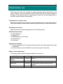
Confirmation of model codes
Referring to the table below check the model codes affixed to the case of the product to
check if the respective codes indicate what was specified when you ordered the product.
Checking accessories
Make sure that your product package has all of the following items
Standard accessories
(1) Quick Reference
(2) Support CD
(3) Mounting fixture (w/ 2 screws)
(4) Terminal cover
(5) Unit decal
Optional accessories
(1) Current transformer (CT) for heater break alarm (when the heater break alarm option
is selected)
(2) Terminal resistor (when the RS-485 communication option is selected)
Options (sold separately)
The following table shows the options available for this product.
Model Name
Infrared Communication
Adapter
Model No.
S5004
USB 1.1
Specification
Shunt resistor
QCS002
250Ω±0.1%
Relay Unit
AP2MC
Converts open collector output to 2-point
contact.
SV No. Selector
KA251
BIN code, switchable between SV1 to SV10
iv
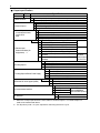
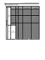
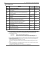
1-input specification
Item
1. Series
Code
Specification
Multi-function controller, DIN 96 x 96 mm
SS Universal-input, 1-input/1-output control, 3 event outputs
2. Basic functions
SD Universal-input, 1-input/2-output control, 3 event outputs
Y Contact 1c, Contact rating: 240 V AC, 2.5 A/resistive load, 1A/ inductive load
I Current 4 to 20 mA DC, Load resistance: 600Ω max.
3. Control Output 1
P SSR drive voltage 12 V±1.5 V DC, Load current: 30 mA max.
V Voltage 0 to 10 V DC, Load current: 2 mA max.
N- None
4. Control Output 2
Y- Contact 1c, Contact rating: 240 V AC 2.5 A/resistive load, 1A/ inductive load
N- selected when basic
function SS is
I- Current 4 to 20 mA DC, Load resistance: 600Ω max.
used
P- SSR drive voltage 12 V±1.5 V DC, Load current: 30 mA max.
V- Voltage 0 to 10 V DC, Load current: 2 mA max.
Standard 06 0 to 10 V DC, Input resistance: Approx.500 kΩ
Not insulated
04 4 to 20 mA DC, Input resistance: 250Ω
05 1 to 5 V DC, Input resistance: Approx.500 kΩ
14 4 to 20 mA DC, Input resistance: 250Ω
Insulated
5. Remote Input/
15 1 to 5 V DC, Input resistance: Approx.500 kΩ
Heater break alarm (for
16 0 to 10 V DC, Input resistance: Approx.500 kΩ
single-phase) *1
31 Heater break alarm (heater current 30 A, CT
Selectable
provided)
only when
Control Output
32 Heater break alarm (heater current 50 A, CT
1 or 2 is Y or P
provided)
0 Without
3 0 to 10 mV DC, Output resistance: 10Ω
6. Analog Output 1
4 4 to 20 mA DC, Load resistance: 300Ω max.
6 0 to 10 V DC, Load current: 2 mA max.
0
Without
3
0 to 10 mV DC, Output resistance: 10Ω
7. Analog Output 2/Sensor Power Supply
4
4 to 20 mA DC, Load resistance: 300Ω max.
6
0 to 10 V DC, Load current: 2 mA max.
8
Sensor power supply 24 V DC 25mA
Standard 0 4 DI, 5 DO
8. External I/O control signals (DI/DO)
1 10 DI, 9 DO
*2
2 10 DI, 13 DO
0 Without
3 RS-485 (not insulated) SHIMADEN
9. Communication interface
protocol/MODBUS
5 RS-485
communication protocol
7 RS-232C
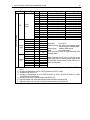
10. Remarks
*1
*2
SR23-
0 Without
9 With
When the 2-output specification is used, either of Control Output 1 or Control Output 2 is
used as the heater break alarm.
Ten DI points (code 1 or 2) are required for switching the SV No. by DI.
v
Contents
1
INSTALLATION & WIRING.................................................................1
1-1
Installation Site ............................................................................................1
1-2
External Dimensions and Panel Cutout .......................................................1
1-3
Mounting......................................................................................................2
1-4
Current Transformer (CT) for Heater Break Alarm ......................................3
1-5
Rear Terminal Arrangement Diagrams........................................................4
1-6
Wiring ..........................................................................................................6
2
NAMES & FUNCTIONS OF PARTS ON FRONT PANEL...................7
3
BASIC OPERATIONS.......................................................................11
3-1
Power ON ..................................................................................................11
3-2
Switching LCD Screen Display and Moving the Cursor .............................12
(1) Switching the screen display........................................................................... 12
3-3
Changing and Registering Data.................................................................13
(1) Entering numerical values............................................................................... 13
(2) Selecting setup items ...................................................................................... 14
4
CONTROL FUNCTION BLOCK DIAGRAMS....................................15
4-1
5
SETUP ..............................................................................................17
5-1
6
1-input, 1-output/2-output ..........................................................................15
Parameter Setup Procedure ......................................................................17
OUTPUT SPECIFICATION & KEY LOCK ........................................19
6-1
Confirming the Output Specification ..........................................................19
6-2
Releasing the Key Lock .............................................................................20
(1) Key lock screen display .................................................................................. 20
(2) Releasing the key lock .................................................................................... 20
7
I/O SETTINGS, INFRARED COMMUNICATION ..............................21
7-1
Output Specifications (2-output specification)............................................21
7-2
Infrared Communication ............................................................................21
7-3
Measuring Range ......................................................................................22
(1) Range setting .................................................................................................. 22
(2) Range scaling ................................................................................................. 22
vi
7-4
Unit ............................................................................................................ 26
7-5
Decimal Point Position............................................................................... 26
(1) Decimal point position ..................................................................................... 26
(2) Switching the lowest digit past the decimal point ............................................ 27
7-6
Cold Junction Compensation..................................................................... 28
(1) Thermocouple cold junction compensation ..................................................... 28
8
I/O AUXILIARY SETTINGS...............................................................29
8-1
PV Compensation Value ........................................................................... 29
(1) PV bias ............................................................................................................ 29
(2) PV filter ............................................................................................................ 29
(3) PV slope .......................................................................................................... 29
8-2
Square Root Extraction Operation............................................................. 30
(1) Enabling the square root extraction operation................................................. 30
(2) Low cut ............................................................................................................ 30
8-3
Control Output ........................................................................................... 31
(1) Action characteristics....................................................................................... 31
(2) Output at standby ............................................................................................ 31
(3) Output at error ................................................................................................. 32
(4) Proportional cycle time .................................................................................... 32
(5) Setting output 2 ............................................................................................... 32
(6) Rate-of-change limiter ..................................................................................... 33
8-4
Ten-Segment Linearizer Approximation .................................................... 33
(1) Enabling ten-segment linearizer approximation .............................................. 33
(2) Setting input points .......................................................................................... 33
8-5
9
Compensating Control Output/Analog Output ........................................... 35
SV VALUE & REMOTE SV VALUE ..................................................37
9-1
Setting the SV Value ................................................................................. 37
(1) SV limiter ......................................................................................................... 37
(2) Set value (SV) ................................................................................................. 37
9-2
Setting the Remote SV Value.................................................................... 38
(1) Monitoring the remote SV................................................................................ 38
(2) Remote tracking .............................................................................................. 38
(3) Remote mode .................................................................................................. 39
9-3
Setting the Remote SV Compensation Value............................................ 40
(1) Remote ratio .................................................................................................... 40
(2) Remote bias .................................................................................................... 41
(3) Remote filter .................................................................................................... 41
(4) Remote scale................................................................................................... 42
vii
9-4
Setting the Remote PID No. and Square Root Extraction Operation.........43
(1) Setting the remote PID No. ............................................................................. 43
(2) Enabling remote square root extraction operation function............................. 43
(3) Low cut............................................................................................................ 44
9-5
Setting the Ramp.......................................................................................44
(1) Ramp value ..................................................................................................... 44
(2) Ramp unit time ................................................................................................ 44
(3) Ramp ratio ...................................................................................................... 45
(4) Executing ramp control ................................................................................... 45
10 PID SETTING....................................................................................47
10-1
Proportional Band (P) ................................................................................47
10-2
Integral Time (I) .........................................................................................47
10-3
Derivative time (D).....................................................................................48
10-4
Manual Reset (MR) ...................................................................................48
10-5
Action Hysteresis (DF)...............................................................................49
10-6
Dead Band (DB) ........................................................................................49
10-7
Set Value Function (SF) ............................................................................51
10-8
Output Limit Value (OUT1L to OUT2H) .....................................................52
10-9
Zone PID ...................................................................................................53
(1) Selecting Zone PID ......................................................................................... 53
(2) Zone hysteresis............................................................................................... 54
(3) PID zone ......................................................................................................... 54
10-10
Auto Tuning Point ......................................................................................55
11 EVENT & DO SETTING....................................................................57
11-1
Monitor Screens ........................................................................................57
(1) DO monitor...................................................................................................... 57
(2) Logic monitor .................................................................................................. 57
11-2
EVENT/DO Action .....................................................................................57
(1) Output characteristics ..................................................................................... 59
(2) Hysteresis ....................................................................................................... 60
(3) Delay time ....................................................................................................... 60
(4) Inhibit action .................................................................................................... 61
(5) Event action at inhibit...................................................................................... 61
11-3
Event Logic Operations .............................................................................62
(1) Logic operation mode (Log MD) ..................................................................... 62
(2) Assigning logic operation input (SRC1, SRC2)............................................... 62
(3) Logic operation input logic (Gate1, Gate2) ..................................................... 63
viii
11-4
Timers/Counters ........................................................................................ 63
(1) Timer time........................................................................................................ 63
(2) Counter............................................................................................................ 64
(3) Assigning input (SRC) ..................................................................................... 64
(4) Mode (Log MD)................................................................................................ 64
12 OPTION (DI, AO, HB, COM) SETTING ............................................65
12-1
DI............................................................................................................... 65
(1) DI monitor screen ............................................................................................ 65
(2) Selecting DI action........................................................................................... 65
12-2
Analog Output ........................................................................................... 67
(1) Analog output type........................................................................................... 67
(2) Scaling analog output ...................................................................................... 67
12-3
Setting the Heater Break/Heater Loop Alarms .......................................... 68
(1) Connecting the current transformer (CT)......................................................... 68
(2) Heater current monitor..................................................................................... 68
(3) Heater Break Alarm current (HBA) .................................................................. 69
(4) Heater Loop Alarm current (HLA).................................................................... 69
(5) Heater Break/Heater Loop Alarm mode (HBM)............................................... 69
(6) Heater Break detection selection (HB) ............................................................ 70
12-4
Communication ......................................................................................... 71
(1) Setting communication .................................................................................... 71
(2) Communication mode (COM).......................................................................... 72
13 KEY LOCK SETTING........................................................................73
13-1
Setting Key Lock........................................................................................ 73
(1) Displaying the key lock screen ........................................................................ 73
(2) Key lock ........................................................................................................... 73
14 MONITORING, EXECUTING & STOPPING OPERATION...............75
14-1
Flow of Basic Screen................................................................................. 75
(1) 1-input specification......................................................................................... 75
14-2
Operations in Basic Screen ....................................................................... 76
(1) Switching the SV No........................................................................................ 76
(2) Output monitor screen ..................................................................................... 76
15 OPERATIONS DURING CONTROL .................................................77
15-1
Monitoring Control ..................................................................................... 77
(1) Basic screen .................................................................................................... 77
(2) Output value display ........................................................................................ 77
15-2
Switching the Execution SV No. ................................................................ 78
ix
15-3
Setting the Execution SV No. ....................................................................78
15-4
Externally Switching the SV No. ................................................................79
15-5
Auto Tuning ...............................................................................................80
(1) Executing and Stopping Auto Tuning.............................................................. 80
(2) Selecting the PID tuning mode ....................................................................... 81
15-6
Self Tuning ................................................................................................81
15-7
Setting Control Output ...............................................................................82
(1) Switching auto/manual of Control Output........................................................ 82
(2) Output value.................................................................................................... 82
(3) MAN key operations........................................................................................ 83
15-8
Control Standby (STBY) ............................................................................84
15-9
Pausing/Resuming Ramp Control (RAMP)................................................85
15-10
Tuning Functions .......................................................................................86
15-10-1 Auto tuning (AT) ..................................................................................... 86
15-10-2 Self tuning............................................................................................... 88
(1) Self tuning: by step response (St) ............................................................. 88
(2) Self tuning: by hunting suppression (Hu) .................................................. 90
16 ERROR DISPLAYS...........................................................................93
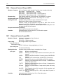
16-1
Operation Check Abnormalities at Power ON............................................93
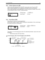
16-2
PV Input Abnormalities ..............................................................................93
16-3
REM Input Abnormalities ...........................................................................94
16-4
Heater Current Abnormalities (option) .......................................................94
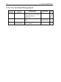
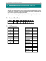
17 LIST OF PARAMETERS...................................................................95
17-1
Basic Screen Group (group 0) ...................................................................95
17-2
Execution Screen Group (group 1) ............................................................95
17-3
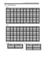
SV Setup Screen Group (group 2).............................................................96
17-4
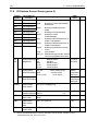
PID Screen Group (group 3)......................................................................97
17-5
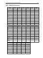
EVENT/DO Screen Group (group 4) .........................................................98
17-6
DI/Options Screen Group (group 5) ......................................................... 100
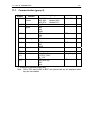
17-7
Communication (group 5) ........................................................................ 101
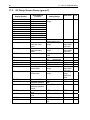
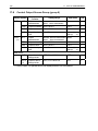
17-8
Control Output Screen Group (group 6) .................................................. 102
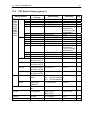
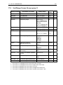
17-9
Unit/Range Screen Group (group 7)........................................................ 103
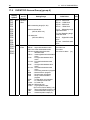
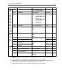
17-10
Lock, etc Screen Group (group 8) ........................................................... 104
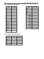
18 PARAMETER SETUP RECORD SHEETS .....................................105
18-1
Product Model Code................................................................................ 105
18-2
SV Parameters ........................................................................................ 105
18-3
PID Parameters ....................................................................................... 106
x
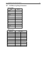
18-4
EVENT/DO Parameters........................................................................... 107
18-5
DI/Options Parameters ............................................................................ 108
18-6
Control Output Parameters...................................................................... 108
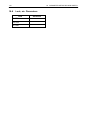
18-7
Unit Measuring Range Parameters ......................................................... 109
18-8
Lock, etc. Parameters.............................................................................. 110
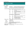
19 SPECIFICATIONS ..........................................................................111
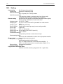
19-1
Display..................................................................................................... 111
19-2
Setting ..................................................................................................... 112
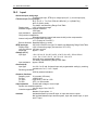
19-3
Input ........................................................................................................ 113
19-4
Control..................................................................................................... 114
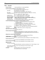
19-5
Event Output ........................................................................................... 115
19-6
External Control Output (DO) .................................................................. 116
19-7
External Control Input (DI)....................................................................... 116
19-8
Logic Operation Functions....................................................................... 117
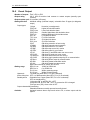
19-9
Heater Break Alarm (option).................................................................... 117
19-10
Analog Output (option) ............................................................................ 118
19-11
Sensor Power Supply (option)................................................................. 118
19-12
Communication (option) .......................................................................... 119
19-13
Infrared Communication .......................................................................... 120
19-14
General Specifications............................................................................. 120
xi
This page left intentionally blank.
xii
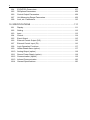
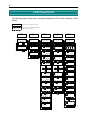
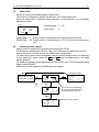
LCD Flow Chart
The following figure shows how to progress through the LCD screen hierarchy on this
device.
Standard screen
Screens that are always displayed
Non-standard
screen
Screens that are displayed depending
on options/setup values.
Group 1
Group 0
Control execution
screens
Basic screens
0-0
SVNo.
1-0
01
OUT1 0
0.0%
GRP
100
SCRN
Exec.Key
GRP
0-1
OUT1
0.0%
GRP
50
SCRN
0-0
100
Group 4
PID screens
Event/DO screens
ENT + SCRN
SCRN
SV and Remote,Ramping
GRP
OFF
OFF
OFF
SCRN
SCRN
ENT + SCRN
RAMP
COM
SV1
0.0℃
ENT + SCRN
1-2
SCRN
2-2
PID and Out Limit, AT
GRP
SCRN
GRP
ENT + SCRN
3-1
PID01-OUT1
P: 3.0%
MR: 0.0%
I: 120s SF: 0.40
D:
30s
3-2
ENT + SCRN
SCRN
0.0℃
ENT + SCRN
ENT + SCRN
SV3
0.0℃
1-0
SCRN
2-4
ENT + SCRN
SV4
Alarm and Status
GRP
PID01 OUT1L:
0.0%
OUT1H: 100.0%
SCRN
2-3
SCRN
ENT + SCRN
SV2
STOP
LOCAL
EVENT/DO
PID
2-1
AT :
MAN :
STBY:
4-0
3-0
SV
GRP
1-1
0
Group 3
SV screens
2-0
CTRL EXEC
50
Group 2
ENT + SCRN
SCRN
3-3
PID02-OUT1
P: 3.0% MR: 0.0%
I: 120s
SF: 0.40
D:
30s
ENT + SCRN
SCRN
3-4
PID02 OUT1L:
0.0%
OUT1H: 100.0%
0.0℃
GRP
SCRN
4-1
DO6
ENT + SCRN
ENT + SCRN
SCRN
3-19
2-10
SV10
0.0℃
ENT + SCRN
2-11 SCRN
REM:
PID10 OUT1
P: 3.0%
I: 120s
D:
30s
MR: 0.0%
SF: 0.40
ENT + SCRN
3-20 SCRN
PID10 OUT1L:
0.0%
OUT1H: 100.0%
0.0℃
ENT + SCRN
2-12 SCRN
SV Limit_L:
0.0 ℃
SV Limit_H: 800.0 ℃
2-13 SCRN
REM Track: NO
ENT + SCRN
ENT + SCRN
REM Bias:
Filt:
Sc_L:
Sc_H:
ENT + SCRN
Zone PID1:
HYS1:
OFF
2.0
ENT + SCRN
3-22 SCRN
Tuning : Auto Tuning
Hunting:
0.5%
AT Point:
0.0 ℃
REM Mode: RSV
2-14 SCRN
3-21 SCRN
0.0℃
OFF
0.0℃
800.0℃
SCRN
ENT + SCRN
3-0
DO7
DO8
DO9
DO10 DO11 DO12 DO13
4-2
ENT + SCRN
SCRN
EV1 SP: 2500.0℃
MD: DEV Hi ACT:N.O.
DF:
2.0℃
IH:OFF
STEV:OFF
DLY:
OFF
ENT + SCRN
SCRN
4-3
EV2 SP: -2500.0 ℃
MD: DEV Low ACT:N.O.
DF:
2.0 ℃
IH:OFF
STEV:OFF
DLY:
OFF
4-4
ENT + SCRN
SCRN
EV3
MD: None
4-5
SCRN
ENT + SCRN
ENT + SCRN
SCRN
DO1
MD: None
SCRN
4-6
DO2
MD: None
4-7
ACT:N.O.
ACT:N.O.
ENT + SCRN
ACT:N.O.
ENT + SCRN
SCRN
DO3
MD: None
ACT:N.O.
ENT + SCRN
SCRN
4-8
DO4
MD: None
ACT:N.O.
SCRN
4-9
DO5
MD: None
ACT:N.O.
4-10
ENT + SCRN
ENT + SCRN
SCRN
DO6
MD: None
ACT:N.O.
ENT + SCRN
2-15 SCRN
SQ. Root: ON
Low Cut : 1.0%
4-17
ENT + SCRN
2-16 SCRN
ENT + SCRN
SCRN
REM PID : 1
Up:
OFF
Down:
OFF
Unit: /Sec
Ratio: /1
DO13
MD: None
ACT:N.O.
RAMP
SCRN
ENT + SCRN
2-0
ENT + SCRN
SCRN
4-0
xiii
Group 5
Group 6
Group 7
Group 8
DI/Option screens
Control output screens
Unit/Range screens
Lock, etc screens
5-0
GRP
GRP
ENT + SCRN
SCRN
5-1
RA/DA, Cycle, Rate
GRP
ENT + SCRN
SCRN
Bias, Filter
SQ.Root, Prox Mode
GRP
GRP
GRP
ENT + SCRN
SCRN
6-1
DI1
DI2
DI3
DI4
DI5
DI6
DI7
DI8
DI9
DI10
5-2
6-2
DI1: None
( TC, RTD input )
7-1
PV Bias :
PV Filter:
SCRN
ENT + SCRN
None
None
None
None
ENT + SCRN
SCRN
6-0
SCRN
ENT + SCRN
SCRN
0.0
OFF
KLOCK
OUTPUT:
IR COM:
[ 1in
OFF
Single
ON
1out 1loop ]
ENT + SCRN
SCRN
7-2
DI4: None
5-3
DI5:
DI6 :
DI7 :
DI8 :
GRP
ENT + SCRN
SCRN
Rate Limiter
OUT1:
OFF
DI2: None
DI3: None
etc
Key Lock, etc
8-1
OUT1 ACT: Reverse
STBY:
0.0%
ERR:
0.0%
CYC:
30s
ENT + SCRN
SCRN
LOCK,
UNIT/RANGE
CTRL OUT
A-Output, H-Break,
Communication
8-0
7-0
6-0
DI/OPTION
ENT + SCRN
SCRN
8-0
RANGE: 06(K3)
Sc_L
0.0℃
Sc_H
800.0℃
UNIT:℃
DP XXXX.X
7-3
ENT + SCRN
SCRN
Figure Normal
CJ
: Internal
ENT + SCRN
SCRN
5-4
ENT + SCRN
DI9: None
DI10: None
7-0
SCRN
5-5
ENT + SCRN
PV Bias :
0.0
PV Filter:
OFF
PV Slope: 1.000
Ao1MD: PV
Ao1_L:
0.0℃
Ao1_H:
800.0℃
ENT + SCRN
SCRN
5-6
SCRN
ENT + SCRN
SCRN
7-2
RANGE: 84(0-5V)
Sc_L
0.0%
Ao2MD: SV
Ao2_L:
0.0℃
Ao2_H:
800.0℃
5-7
( mV, V input )
7-1
Sc_H
UNIT:%
100.0%
DP XXXX.X
ENT + SCRN
SCRN
ENT + SCRN
7-3
Heater [ 0.0A ]
HBA:
OFF
HLA:
OFF
HBM: Lock HB OUT1
SCRN
ENT + SCRN
5-8
SCRN
5-10
ON
A 1:
B 1:
ENT + SCRN
COM DATA:
PARI:
STOP:
DELY:
7
EVEN
1
10 ms
ENT + SCRN
SCRN
7-4
PMD:
COM PROT: SHIMADEN
ADDR:
1
BPS : 9600
MEM : EEP
5-9
SQ.Root: ON
Low Cut: 1.0%
0.00%
0.00%
ENT + SCRN
SCRN
7-5
A
B
A
B
2:
2:
3:
3:
0.00%
0.00%
0.00%
0.00%
ENT + SCRN
SCRN
ENT + SCRN
SCRN
COM CTRL: STX_ETX_CR
BCC: ADD
SCRN
ENT + SCRN
7-9
A
B
A
B
10:
10:
11:
11:
0.00%
0.00%
0.00%
0.00%
ENT + SCRN
SCRN
5-0
7-0
When the DISP key is pressed at a screen other than the 0-0 basic screen, the 0-0 basic
screen is returned to.
xiv
This page left intentionally blank.
1 INSTALLATION & WIRING
1
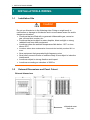
1-1
1
INSTALLATION & WIRING
Installation Site
Caution
Do not use this device in the following sites. Doing so might result in
malfunction or damage to this device and in some cases cause fire and/or
dangerous situations.
Locations that are filled with or generate inflammable gas, corrosive
gas, dirt and dust, smoke, etc.
Locations that are subject to water droplets, direct sunlight or strong
radiated heat from other equipment
Locations where the ambient temperature falls below -10°C or rises
above 50°C
Locations where dew condensation forms and the humidity reaches 90% or
more
Near equipment that generates high-frequency noise
Near heavy current circuits or locations likely to be subject to inductive
interference
Locations subject to strong vibration and impact
Locations exceeding an elevation of 2000 m
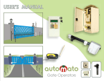
1-2
External Dimensions and Panel Cutout
External dimensions
-w/terminal cover
Unit: mm
2
1 INSTALLATION & WIRING
Panel cutout
or more
or more
Unit: mm
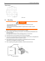
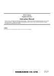
1-3
Mounting
Caution
To ensure safety and maintain the functions of this device, do not
disassemble this device.
If this device must be disassembled for replacement or repair, contact
your dealer.
Follow the procedure below to mount this device on a panel.
1. Drill mounting holes referring to the panel cutout dimensions described in the
previous section.
The applicable thickness of the mounting panel is 1.0 to 8.0 mm.
2. Press this device into the panel from the front of the panel.
3. Insert the mounting fixtures at the top and bottom of this device, and tighten the
screws from behind to fasten the device in place.
4. Over-tightening the screws may deform or damage the device housing.
Take care not to tighten the screws too tight.
5. After completing wiring after installation, attach the terminal cover.
Mounting fixture
SR23
Mounting fixture
1 INSTALLATION & WIRING
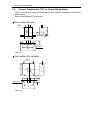
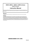
1-4
3
Current Transformer (CT) for Heater Break Alarm
The CT can be used when the heater break alarm (option) is selected in the product
specifications.
Either of the following CT is provided.
For 0 to 30A (CTL-6-S)
3
10.5
25
5.8
10
21
30
40
2-3.5
Unit: mm
For 0 to 50A (CTL-12-S36-8)
40
2.36
15
12
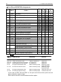
30
40
Unit: mm
7.5
2-M3 depth 4
4
1 INSTALLATION & WIRING
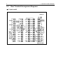
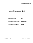
1-5
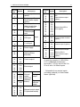
Rear Terminal Arrangement Diagrams
1-input model
1 INSTALLATION & WIRING
Terminal
Symbol
No.
5
Description
1
2
+
-
Analog output 1
(option)
3
4
+
-
Analog output 2 or
Sensor power supply
(option)
Remote input/
Heater break alarm *
CT input (option)
5
6
+
-
8
10
+
-
mV,
Thermocouple
input
8
10
11
A
B
B
RTD input
7
10
+
-
V, mA input
45
46
L
N
Power supply
Grounding (internal
shorting across
terminals)
47
48
49
50
51
Input
COM +
NO - Control output 1
NC
52
53
54
55
COM
EV1
EV2
EV3
23
COM
24
25
26
DO1
DO2
DO3
27
28
DO4
DO5
29
30
31
32
33
DI1
DI2
DI3
DI4
COM
Event output
External
control
output DO
(standard
feature)
Darlington
output
Open
collector
output
External control output
D1 (standard feature)
Terminal
Symbol
No.
Description
34
35
36
37
DO6
DO7
DO8
DO9
External control output
DO
Open collector output
(option)
38
39
40
41
42
43
44
DI5
DI6
DI7
DI8
DI9
DI10
COM
External input DI5 to
DI10 (option)
12
13
14
SG
SD+
RD-
Communication function
(option)
15
16
17
COM +
NO- Control output 2 (option)
NC
18
19
20
21
22
DO10
DO11
DO12
DO13
DO COM
External control output
DO10 to DO13
Open collector output
(option)
A receiving resistor of 1/2W 250Ω
0.1% is attached across input
terminals (7-10) for use for the 0 to
20 mA, and 4 to 20mA inputs.
* Selectable from remote inputs
(including optional) or Heter break
alarm (optional).
6
1 INSTALLATION & WIRING
1-6
Wiring
Caution
To prevent electric shock, always turn off and disconnect this device
from the power supply before starting wiring.
Do not touch wired terminals or charged parts with your hands while
the power is supplied.
Pay attention to the following points when performing wiring:
Check that the wiring is free from mistakes according to "1-5 Rear Terminal
Arrangement Diagrams."
Use crimped terminals that accommodate an M3 screw and that have a width of 6.2
mm or less.
For thermocouple input, use a compensation wire compatible with the type of thermocouple.
For RTD input, the resistance of a single lead wire must be 10Ω or less and the three
wires must have the same resistance.
The input signal lead must not be passed along the same conduit or duct as that for
high-voltage power lines.
Shield wiring (single point grounding) is effective against static induction noise.
Short interval twisted pair wiring is effective against electromagnetic induction noise.
When wiring, use wire or cable (minimum 1 mm2 cross-sectional area) of 600 V
grade PVC insulated wire or equivalent wire having the same rating.
For wiring the ground, ground the ground terminal with the earth resistance at less
than 100Ω and with wire 2 mm2 or thicker.
Two earth terminals are provided, each connected internally. One is for the ground
connection, and the other is for connecting the shield of the signal lead. Do not use
the earth terminals for crossover wiring of the power system ground lead.
If this device is considered as being susceptible to noise caused by the power supply,
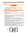
attach a noise filter to prevent abnormal functioning.
Install a noise filter onto a grounded panel, and make the wire connecting the noise
filter output and the power supply terminal on this controller as short as possible.
Making the wiring shortest
Noise Filter
100 to
240V AC
Controller
45 100
IN
OUT
46
47
Earth
Recommended noise filter : TDK ZMB2203-13
to
240V AC
50/60H z
2 NAMES & FUNCTIONS OF PARTS ON FRONT PANEL
2
7
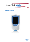
NAMES & FUNCTIONS OF PARTS ON FRONT
PANEL
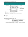
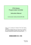
⑤ LED indicators
① PV display
② SV display
⑥ Infrared interface
③ LCD display
④
Front panel key
switches
1 PV display
Displays the measured value (PV value).
Displays an error message when an error (e.g. scale over) occurs.
2 SV display
Displays the target set value (SV value).
3 LCD display (21 characters x 4 lines, max.)
SV No. display
Output (OUT) display
Displays the current target setting value (SV) No..
Displays the control output value by a numerical
value and a bar graph as a percentage (%).
Screen title display
Displays the screen group title in the respective
screen group top screen.
Setup parameter display Displays the parameters that can be selected and
displayed by front key operation.
8
2 NAMES & FUNCTIONS OF PARTS ON FRONT PANEL
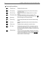
4 Front panel key switches
DISP
(Display key)
GRP
(Group key)
SCRN
Displays the basic screen.
Changes the screen group. Or, returns to the screen
group top screen.
(Screen key)
Switches the parameter display screen in a screen
group.
(Parameter key) Selects the parameter to set up or change. The
parameter to be changed is indicated by the cursor ( ).
(Shift key)
Moves the digit in set numerical values.
(Down key)
(Up key)
Decrements parameters and numerical values during
setup.
Increments parameters and numerical values during
setup.
Registers data or parameter numerical values.
ENT
(Entry key)
SV
(SV key)
Switches the execution SV No. in the basic screen. In
screens other than the basic screen, the execution SV
No. can be switched when the display is switched to the
basic screen.
(Manual key)
Used for manual output (MAN). Switches to the output
monitor screen whichever screen is displayed. With the
output monitor displayed, you can use the
keys to switch to manual output.
MAN
2 NAMES & FUNCTIONS OF PARTS ON FRONT PANEL
9
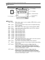
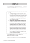
5 LED indicators
STBY RMP MAN REM
⑤ LED indicators
EV1 EV2 EV3 D01 D02 D03 D04 D05 EXT COM
① PV display
② SV display
⑥ Infrared interface
③ LCD display
④
Front panel key
switches
Status lamps
STBY green
RMP
green
MAN
REM
EV1
EV2
EV3
DO1
DO2
DO3
DO4
DO5
EXT
green
green
orange
orange
orange
orange
orange
orange
orange
orange
green
COM green
AT
green
OUT1 green
OUT2 green
Blinks when output is set to standby (STBY=ON) by control
execution/standby.
Blinks during execution of ramp control, and lights while ramp
control is paused.
Blinks when control output is set to manual operation (MAN).
Lights when remote setting (REM) is set in SV No. selection.
Lights during EV1 action.
Lights during EV2 action.
Lights during EV3 action.
Lights during DO1 action.
Lights during DO2 action.
Lights during DO3 action.
Lights during DO4 action.
Lights during DO5 action.
Lights when external switch setting (EXT) is set when multi-SV
No. selection (SV select) is switched to.
Lights when communication (COM) mode is selected.
Blinks during execution of auto tuning or lights during holding
of auto tuning.
When control output is current or voltage output, the
brightness of this lamp changes according to fluctuation of
Control Output 1, and during contact or SSR drive voltage
output, this lamp lights when Control Output 1 is ON and goes
out when Control Output 1 is OFF.
When control output is current or voltage output, the
brightness of this lamp changes according to fluctuation of
Control Output 2, and during contact or SSR drive voltage
output, this lamp lights when Control Output 2 is ON and goes
out when Control Output 2 is OFF.
10
2 NAMES & FUNCTIONS OF PARTS ON FRONT PANEL
This page left intentionally blank.
3 BASIC OPERATIONS
3
11
BASIC OPERATIONS
3-1
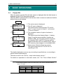
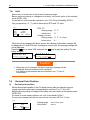
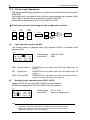
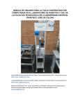
Power ON
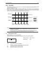
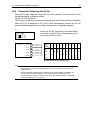
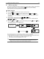
When the power is turned ON, the basic screen is displayed after the initial screen is
displayed on the LCD for about three seconds.
When the SR23 is powered ON for the first time, check on screen to make sure that this
device is the one you ordered.
Power ON
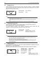
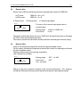
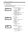
1 The series name is displayed.
1
SR23
CONTROLLER
2 The I/O type is displayed.
The figure shows a thermocouple (TC) set for
Input 1, current (I) set for Output 1, and contact
(Y) set for Output 2.
INPUT1: TC
2
3
OUT 1 :
OUT 2 :
AO1
AO2
COM
SPS
:YES
:YES
:YES
:NO
SV No.
4
I
Y
DI/DO:YES
DO : NO
HB : NO
01
OUT1 0
30.0%
50
100
3 The installation status of option functions is
displayed.
The figure shows that Analog Output 1, Analog
Output 2 and the communication function are
installed (YES), DI (10 points) and DO (9 points)
are installed (YES), and DO 13 points and the
heater break alarm are not installed (NO), and no
SPS (sensor power supply) is not available (NO).
4 Basic screen (Monitor Group top screen)
The figure shows that OUT1 of SV No.1 is
outputting at 30%.
The details displayed on screen vary according to specifications, or according to
preset function specifications.
The basic screen is the "SV No., output value display screen."
For details on operations in the basic screen, see "14-1 Flow of Basic Screen."
Note
The actually installed numbers for external DI or DO can be confirmed with the
above 3 screen.
LCD Display
DI/DO
DO
NO
NO
YES
NO
YES
YES
Actual numbers
DI
DO
4
5
10
9
10
13
12
3 BASIC OPERATIONS
3-2
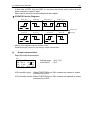
(1)
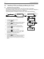
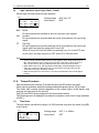
Switching LCD Screen Display and Moving the Cursor
Switching the screen display
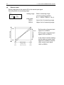
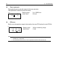
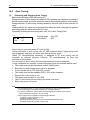
For details on moving between screens, see "LCD Flow Chart" in the preface.
The operation screens of this device are configured so that screens are displayed in
order from the most frequently used screen in regular use.
The following shows an example of screens in the 1-input/1-output specification.
①
DISP
SV No.
010
OUT1
30.0%
50
CH
1
② CTRLEXEC
CTRL EXEC
②
GRP
Exec.Key.
PID
PID
PID and
Limit,
AT
PID
andOutOut
Limit
Exec.Key
100
The next
次の
screen display
画面表示
GRP
GRP
SCRN
1 To display the basic screen
Press the DISP key.
2 To switch the display between screen groups
Press the GRP key to successively switch
screen group top screens.
3 To switch setup screens within groups
Press the SCRN key to successively switch
screens.
4 To move the cursor in a screen
Press the
key to move the cursor ( )
blinking) when there are two or more
parameters in the same screen.
5 To display the top screen
Press the GRP key in a respective parameter
setup screen other than the basic screen
group to switch to the top screen of a screen
group.
②
③
PID01- OUT1
P
3.0%
I:
120s
D:
30s
MR: 0.0%
SF: 0.40%
SCRN
③
PID01
OUT1L
OUT1H
OUT2L
OUT2H
PID01
OUT1L
OUT1H
OUT2L
OUT2H
:
:
:
0.0%
100.0%
0.0%:
100.0%
④
:
:
:
0.0%
100.0%
0.0%:
100.0%
GRP
3 BASIC OPERATIONS
3-3
13
Changing and Registering Data
Basically, set up and change parameters while confirming the LCD screen display.
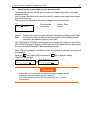
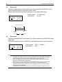
(1)
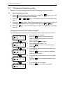
Entering numerical values
1. When there are two or more parameters, press the
cursor ( ) to the parameter to be changed.
2. Press the
blinks.
or
,
key to move the
keys. The smallest digit of the numerical value
3. Press the
key again. Move the blinking section in the numerical value to
the digit to be changed, and change the value using the
or
key.
4. Press the ENT key. The numerical value is fixed and registered, and stops
blinking.
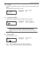
Changing a numerical value setting (example)
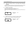
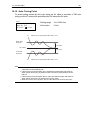
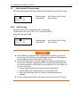
The following shows the procedure for changing the value of PID parameter I to 100 s.
①
PID01-OUT1
P:
3.0%
I:
120s
D:
30s
MR: 0.0%
SF: 0.40
②
PID01-OUT1
P:
3.0%
I:
120s
D:
30s
MR: 0.0%
SF: 0.40
③
PID01-OUT1
P:
3.0%
I:
120s
D:
30s
MR: 0.0%
SF: 0.40
▼
④
PID01-OUT1
P:
3.0%
I:
100s
D:
30s
MR: 0.0%
SF: 0.40
ENT
⑤
PID01-OUT1
P:
3.0%
I:
100s
D:
30s
MR: 0.0%
SF: 0.40
1 To move between screens
Press the GRP key three times in the initial
screen to display the top screen of the PID
screen (group 3).
Next, press the SCRN key once.
2 To move the cursor from P to I
Press the
key once to move the blinking
cursor ( ) to I.
3 To make the I numerical value blink and move
to the 10's digit
Press the
key twice to move the blinking
cursor to the 10's digit.
4 To change the numerical value of the 10's digit
to 100
Press the
key to change the display from
"2" to "0".
5 To fix and register the setting
Press the ENT key to fix the new setting.
14
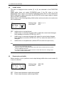
(2)
3 BASIC OPERATIONS
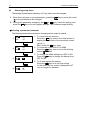
Selecting setup items
The settings of parameters marked by a key mark cannot be changed.
1. When there are two or more parameters, press the
key to move the cursor
( ) to the parameter to be changed.
2. Change the parameter settings by the
or
key, check the setting, and
press the ENT key to fix and register settings. The character stops blinking.
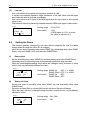
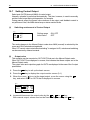
Selecting a parameter (example)
The following shows the procedure for changing control output to manual.
① MAN :
AT
STBY:
OFF
OFF
OFF
AT :
② MAN
STBY:
OFF
OFF
OFF
AT :
③ MAN
STBY:
OFF
ON
OFF
▼
ENT
AT
④ MAN
STBY:
OFF
ON
OFF
1 To move between screens
Press the GRP key once in the initial screen to
display the top screen of the execution screen
(group 1).
Next, press the SCRN key once.
2 To move the cursor from AT to MAN
Press the
key once to move the blinking
cursor ( ) to MAN.
3 To change the MAN setting from OFF to ON
key to change the display from
Press the
OFF to ON.
4 To fix and register the setting
Press the ENT key to fix the new setting.
In this case, the key mark is displayed as AT
can no longer be operated.
4 CONTROL FUNCTION BLOCK DIAGRAMS
4
15
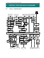
CONTROL FUNCTION BLOCK DIAGRAMS
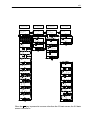
4-1
1-input, 1-output/2-output
USB
PV input
DI7 to DI10
Range selection
EXT_SV
assignment
SV value
setteing
Unit
selection
Scaling
Multi-SV No.
Multi-SV No.
external
selection
Decimal
point setting
Square root
extraction
operation
REM scaling
SV No.1 to 10
Sensor
input (TC,
RTD)
Linear input
(mV, V,
mA)
Remote input
internal
selection
DI input
Heater break
CT input
DI
Heater break
alarm
assignments
Square root
extraction
operation
Heater loop
alarm
REM filter
Alarm mode
(lock/real)
SV No. switching
Ratio logic
operation
External CJ
Infrared
communications
adapter
Ramp control
Ten-segment
linealization
REM bias
Linearization
PV filter
Local/REM switching
Infrared interface
REM tracking
Ramp
bias
PV slope
PV bias
SHIMADEN
standard
protocol
SV limit
Execution PV
Execution SV
Execution/standby, processing of logic operations, front panel infrared communications
Characteristics
switching
Output at
error
Rate-of-change
limiter
Output at
standby
EV, DO type selection
Hysteresis
Control
Output 2
control
logic
Output limiter
DI
assignments
Auto/manual switching
PID, control logic
operations
I, V
Analog
output
type
selection
A_out1
scaling
A_out2
scaling
DI assignments
Protocol
selection
SHIMADEN
standard/
ModBus
Logic operation
timers/counters
Output charasteristics
(NO, NC)
Y, P
Communication
conditions
selection
Status, HB
Standby action
Delay time
Analog
output
type
selection
RS-232C/
RS-485
Proportional
cycle
Control Output1
Control Output2
EV, DO output
Analog
Output 1
Analog
Output 2
Serial
communication
16
4 CONTROL FUNCTION BLOCK DIAGRAMS
This page left intentionally blank.
5 SETUP
5
17
SETUP
5-1
Parameter Setup Procedure
Follow the procedure below to set up this device or change device settings when you
use this device for the first time, change the operation parameters during use, or the
control target device has been changed, for example.
Caution
With some operations, when you initialize this device, all parameter
settings return to their factory defaults.
Before you initialize this device, note down and retain settings as
required.
It is assumed that experienced personnel familiar with basic operation of this
device will set up this device.
Users other than device manufacturers should thoroughly familiarize themselves
with the functions to be used before they start to operate or set up this device.
Basic operations and setup of this device are described in detail from Chapter 6
onwards by each screen group.
Some screens and parameters are not displayed when option functions are not
added on or when option functions are not selected.
For an overview of operation screens and how to move between screens, see
"LCD Flow Chart" in the preface. For an overview of setup parameters, see "17
List of Parameters."
Set up parameters in the order shown below.
1. Confirm the Output Specification and Release the Key Lock.
Perform this as necessary.
For details, see "Chapter 6."
2. I/O Settings.
For details, see "Chapter 7."
3. I/O Auxiliary Settings.
For details, see "Chapter 8."
4. Set up the SV Value and Remove SV Value.
For details, see "Chapter 9."
5. PID Settings.
For details, see "Chapter 10."
6. EVENT/DO Settings.
For details, see "Chapter 11."
7. Option (DI, AO, HB, COM) Settings.
For details, see "Chapter 12."
18
5 SETUP
8. Key Lock Setting.
After parameters including option functions are set or changed, set the key lock
as necessary to prevent inadvertent operation.
For details, see "Chapter 13."
9. Monitoring, Executing & Stopping operation.
For details, see "Chapter 14."
10. Operations During Control.
For details, see "Chapter 15."
6 OUTPUT SPECIFICATION & KEY LOCK
6
19
OUTPUT SPECIFICATION & KEY LOCK
Perform the following as necessary.
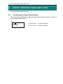
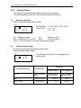
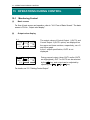
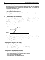
6-1
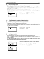
Confirming the Output Specification
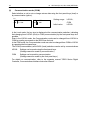
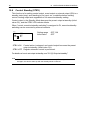
The current output specification is displayed at the bottom row of the key lock, number of
outputs setting screen (No.8-1).
8-1
KLOCK:
OFF
OUTPUT: Single
IR COM: ON
[ 1in 1out 1loop ]
1in 1out 1loop: 1-output controller
1in 2out 1loop: 2-output controller
20
6 OUTPUT SPECIFICATION & KEY LOCK
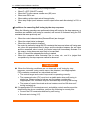
6-2
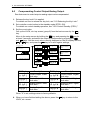
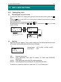
(1)
Releasing the Key Lock
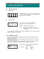
Key lock screen display
To call up the LOCK, etc. screen group (group 8) from the basic screen, press the GRP
key.
Press the SCRN key in the LOCK, etc. screen group to switch to the screens for making
and changing setups.
Select parameters in screens by pressing the
key.
Set parameters by pressing the
,
or
key, and press the ENT key to fix
and register settings.
0-0 Basic screen
SVNo.
GRP
01
OUT1 0
0.0%
50
100
8-0 Lock screen
LOCK, etc.
Key Lock, etc.
DISP
SCRN
Dotted line indicates that
the same key must be pressed
more than once.
(2)
ENT + SCRN
8-1
KLOCK
OFF
OUTPUT Dual
IR COM: ON
[ 1in 2out 1loop ]
GRP
Releasing the key lock
When the key lock is applied, the (key mark) is displayed at the relevant parameter on
the LCD screen indicating that the parameter cannot be set or its settings changed. The
following shows the procedure for releasing the key lock.
8-1
KLOCK:
OFF
Tuning: Auto Tuning
OUTPUT: Single
[ 1in 1out 1loop ]
OFF
LOCK1
LOCK2
LOCK3
Setting range
Initial value
OFF, LOCK1, LOCK2, LOCK3
OFF
Releases the key lock
Locks parameters other than SV related, AT, MAN, or EVENT/ DO action
point
Locks parameters other than SV related parameters
Locks all parameters (excluding the key lock parameter itself)
For details on parameters that are locked, see "17 List of Parameters."
7 I/O SETTINGS, INFRARED COMMUNICATION
7
21
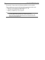
I/O SETTINGS, INFRARED COMMUNICATION
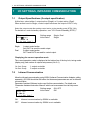
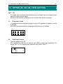
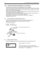
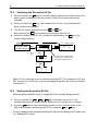
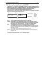
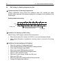
7-1
Output Specifications (2-output specification)
At this item, select either 1-output action (Single) or 2-output action (Dual).
When action is set to Single, control output becomes the output of OUT1 only.
Select the output mode after setting control action to the standby mode (STBY: ON).
For details on control standby operation, see "15-8 Control Standby (STBY)."
8-1
KLOCK:
OFF
OUTPUT: Single
IR COM: ON
[ 1in 1out 1loop ]
Single
Setting range
Initial value
Single, Dual
Single
1-output control action
Only OUT1 is used for control output.
2-output control action
OUT1 and OUT2 are used for control output.
Dual
Displaying the current operation mode
The current operation mode is displayed at the bottom line of the key lock, tuning mode
(display only) and number of outputs setup screen (No. 8-1).
1in 1out 1loop
1in 2out 1loop
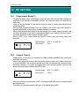
7-2
1-output controller
2-output controller
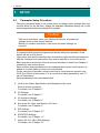
Infrared Communication
Allow the infrared communication using S5004 (Infrared Communication Adapter, selling
separately). IR COM should be ON before the instrument parameters are set via infrared
communication.
Parameter Assistant Software is also used for this communication. For details, see
“Parameter Assistant Instruction Manual” which can be accessed from its Help menu.
8-1
KLOCK :
OUTPUT:
IR COM:
[ 1in
ON
OFF
OFF
Dual
ON
2out 1loop ]
Setting range
Initial value
ON, OFF
ON
Infrared communication by S5004 is available.
Infrared communication by S5004 is not available.
22
7 I/O SETTINGS, INFRARED COMMUNICATION
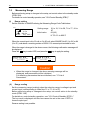
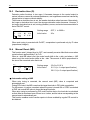
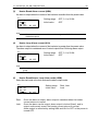
7-3
Measuring Range
Before performing setup or changes to the setup, set control action to the standby mode
(STBY: ON).
For details on control standby operation, see "15-8 Control Standby (STBY)."
(1)
Range setting
Set the code No. to RANGE referring the Measuring Range Code Table below.
7-2
Setting range
RANGE: 06(K3)
Sc_L
0.0℃
800.0℃
Sc_H
UNIT:℃
DP XXXX.X
Initial value
01 to 19, 31 to 58, 71 to 77, 81 to
87
06 (K3)
K T/C 0.0 to 800°C
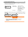
When the current input is 4 to 20 mA or 0 to 20 mA, select RANGE No.85 (1 to 5V) or 84
(0 to 5V), and attach a receiving resistor of 250Ω 0.1% across input terminals for use.
When the range is changed in the above screen, the following confirmation message will
be displayed.
Press the
key to select YES, and press the ENT key to apply the setting.
WARNING
Params Initialize
proceed? NO
WARNING
Params Initialize
proceed? YES
Caution
When the range is changed, the above warning message will be
displayed, and parameters will be initialized.
For details on parameters that are initialized, see "17 List of
Parameters"
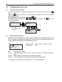
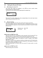
(2)
Range scaling
Set the measuring range (scaling) when the selection range is voltage input and
current input (corresponding to code Nos.71 to 77, 81 to 87).
Before performing setup or changes to the setup, set control action to the standby
mode (STBY: ON).
For details on control standby operation, see "15-8 Control Standby (STBY)."
The key mark is displayed and this item cannot be set in the case of RTD or
thermocouple input.
Reverse scaling is not possible.
7 I/O SETTINGS, INFRARED COMMUNICATION
23
The maximum span is (Sc_H - Sc_L) ≤ 30000.
When an Sc_L is set that causes the span to exceed 30000, a value that does not
exceed span is automatically set to Sc_H.
7-2
RANGE : 86(0 ~10 V)
Sc_L:
0.0 %
Sc_H:
100.0 %
UNIT :%
DP: XXXX.X
Settable range
Measuring range
Initial value
-19999 to 30000 Unit
Minimum span: 10 Unit
Maximum span: 30000 Unit
Any setting within the above
ranges is possible.
(Note that Sc_L<Sc_H)
Sc_L: 0 Unit,
Sc_H:1000 Unit
When scaling is changed in the above screen, the following confirmation message will
be displayed.
Press the
key to select YES, and press the ENT key to apply the setting. The range
will be changed.
WARNING
Params Initialize
proceed? NO
WARNING
Params Initialize
proceed? YES
Caution
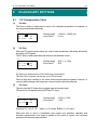
When the range is scaled, the above warning message will be
displayed, and parameters will be initialized.
For details on parameters that are initialized, see "17 List of
Parameters."
24
7 I/O SETTINGS, INFRARED COMMUNICATION
Measuring Range Code Table
Input Type Sensor Type Code Symbol
Universal Input
B
R
S
K
K
K
K
K
Thermo E
couple J
T
N
PL II
PR40 - 20
WRe5-26
U
L
K
AuFe-Cr
RTD
*1
*2
*2
*3
*4
*5
Pt100
(old) JIS/IEC
01
02
03
04
05
06
07
08
09
10
11
12
13
14
15
16
17
18
19
31
32
33
34
35
36
37
38
39
40
41
42
43
44
B
R
S
K1
K2
K3
K4
K5
E
J
T
N
PLII
PR40-20
WRe5-26
U
L
K
AuFe - Cr
Pt 1
Pt 2
Pt 3
Pt 4
Pt 5
Pt 6
Pt 7
Pt 8 *6
Pt 9
Pt10
Pt11
Pt12 *7
Pt13
Pt14
Measuring range
Measuring range
0.0 to 1800.0
0.0 to 1700.0
0.0 to 1700.0
-100.0 to 400.0
0.0 to 400.0
0.0 to 800.0
0.0 to 1370.0
-200.0 to 200.0
0.0 to 700.0
0.0 to 600.0
-200.0 to 200.0
0.0 to 1300.0
0.0 to 1300.0
0.0 to 1800.0
0.0 to 2300.0
-200.0 to 200.0
0.0 to 600.0
10.0 to 350.0
0.0 to 350.0
-200.0 to 600.0
-100.00 to 100.00
-100.0 to 300.0
-60.00 to 40.00
-50.00 to 50.00
-40.00 to 60.00
-20.00 to 80.00
0.000 to 30.000
0.00 to 50.00
0.00 to 100.00
0.00 to 200.00
0.00 to 300.00
0.0 to 300.0
0.0 to 500.0
0 to 3300
0 to 3100
0 to 3100
-150.0 to 750.0
0.0 to 750.0
0.0 to 1500.0
0.0 to 2500.0
-300.0 to 400.0
0.0 to 1300.0
0.0 to 1100.0
-300.0 to 400.0
0.0 to 2300.0
0.0 to 2300.0
0 to 3300
0 to 4200
-300.0 to 400.0
0.0 to 1100.0
10.0 to 350.0
0.0 to 350.0
-300.0 to 1100.0
-150.0 to 200.0
-150.0 to 600.0
-80.00 to 100.00
-60.00 to 120.00
-40.00 to 140.00
0.00 to 180.00
0.00 to 80.00
0.00 to 120.00
0.00 to 200.00
0.0 to 400.0
0.0 to 600.0
0.0 to 600.0
0.0 to 1000.0
°C
°C
°C
°C
°C
°C
°C
°C
°C
°C
°C
°C
°C
°C
°C
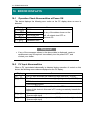
°C
°C
K
K
°C
°C
°C
°C
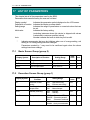
°C
°C
°C
°C
°C
°C
°C
°C
°C
°C
°F
°F
°F
°F
°F
°F
°F
°F
°F
°F
°F
°F
°F
°F
°F
°F
°F
K
K
°F
°F
°F
°F
°F
°F
°F
°F
°F
°F
°F
°F
°F
°F
7 I/O SETTINGS, INFRARED COMMUNICATION
Input Type Sensor Type Code Symbol
RTD
JPt100
(old)JIS
Universal Input
-10 to 10 mV
0 to 10 mV
0 to 20 mV
Voltage
0 to 50 mV
(mV)
10 to 50 mV
0 to 100 mV
-100 to 100 mV
45
46
47
48
49
50
51
52
53
54
55
56
57
58
71
72
73
74
75
76
77
JPt 1
JPt 2
JPt 3
JPt 4
JPt 5
JPt 6
JPt 7
JPt 8 *6
JPt 9
JPt10
JPt11
JPt12 *7
JPt13
JPt14
-10 to 10 mV
0 to 10 mV
0 to 20 mV
0 to 50 mV
10 to 50 mV
0 to 100 mV
-100 to 100
mV
-1 to 1 V
0 to 1 V
0 to 2 V
0 to 5 V
1 to 5 V
0 to 10 V
-10 to 10 V
25
Measuring range
-200.0 to 500.0
-100.00 to 100.00
-100.0 to 300.0
-60.00 to 40.00
-50.00 to 50.00
-40.00 to 60.00
-20.00 to 80.00
0.000 to 30.000
0.00 to 50.00
0.00 to 100.00
0.00 to 200.00
0.00 to 300.00
0.0 to 300.0
0.0 to 500.0
°C
°C
°C
°C
°C
°C
°C
°C
°C
°C
°C
°C
°C
°C
Measuring range
-300.0 to 900.0
-150.0 to 200.0
-150.0 to 600.0
-80.00 to 100.00
-60.00 to 120.00
-40.00 to 140.00
0.00 to 180.00
0.00 to 80.00
0.00 to 120.00
0.00 to 200.00
0.0 to 400.0
0.0 to 600.0
0.0 to 600.0
0.0 to 900.0
°F
°F
°F
°F
°F
°F
°F
°F
°F
°F
°F
°F
°F
°F
Initial value:
0.0 to 100.0
Measuring range: Any value in the following ranges
can be set by the scaling function.
Scaling range: -19999 to 30000 counts
Span:
10 to 30000 counts
Scale over occurs when the input measured value
exceeds 32000.
81
82
When used with 0 to 20 mA, 4 to 20 mA current
83
input, select either of measuring range codes 84 and
Voltage
84
85, and attach a shunt resistor of 1/2W 250Ω±0.1%
(V)
85
to the input terminals.
86
87
*1: In the case of thermocouple B, accuracy is not guaranteed at temperatures 400°C and 750°F or
below.
*2: Accuracy at temperatures -100°C (-148°F) or below ±(0.5%FS+1 digit).
*3: Accuracy is ±(0.3%FS+1°C).
*4: Accuracy of thermocouple K is ±(0.75%FS+1K)/10.0 to 30.0K, ±(0.30%FS+1K)/30.0 to 70.0K,
±(0.25%FS+1K)/70.0 to 350.0K.
*5: Accuracy of the AuFe-Cr thermocouple is ±(0.25%FS+1K).
*6: Higher limit scale over occurs when the input measured value exceeds 32.000.
*7: Higher limit scale over occurs when the input measured value exceeds 320.000.
-1 to 1 V
0 to 1 V
0 to 2 V
0 to 5 V
1 to 5 V
0 to 10 V
-10 to 10 V
26
7 I/O SETTINGS, INFRARED COMMUNICATION
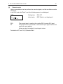
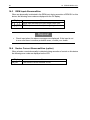
7-4
Unit
Select the unit to be used in the preset measuring range.
Before performing setup or changes to the setup, set control action to the standby
mode (STBY: ON).
For details on control standby operation, see "15-8 Control Standby (STBY)."
Only temperature (°C, °F) can be selected for RTD and TC input.
7-2
RANGE: 86(0~ 10V) C H
1
Sc_L:
0.0℃
Sc_H:
100.0℃
UNIT: ℃ DP: XXXX.X
RTD, TC
Setting range
Initial value
Voltage, Current
Setting range
Initial value
°C, °F
°C
°C, °F, %, None
%
When the unit is changed in the above screen, the following confirmation message will
be displayed at TC and RTD input. At voltage or current input, this warning message will
not be displayed.
Press the
key to select YES, and press the ENT key to apply the setting. The unit
will be changed.
WARNING
Params Initialize
proceed? NO
WARNING
Params Initialize
proceed? YES
Caution
When the unit is changed, the above warning message will be
displayed, and parameters will be initialized.
For details on parameters that are initialized, see "17 List of
Parameters."
7-5
Decimal Point Position
(1)
Decimal point position
Set the decimal point position in the PV display screen when the selection range is
voltage input and current input (corresponding to code Nos.71 to 77, 81 to 87).
Before performing setup or changes to the setup, set control action to the standby mode
(STBY: ON).
For details on control standby operation, see "15-8 Control Standby (STBY)."
The key mark is displayed and this item cannot be set in the case of RTD or TC input.
7-2
RANGE : 86 ( 0 ~ 10 V )
CH
Sc _ L:
0. 0 %
1
Sc _ H:
100 . 0 %
UNIT :%
DP : XXXX . X
Setting range
Initial value
xxxx.x to x.xxxx
xxxx.x
7 I/O SETTINGS, INFRARED COMMUNICATION
(2)
27
Switching the lowest digit past the decimal point
The lowest digit past the decimal point of measuring ranges determined by the range
setting can be set.
Note, however, that this function cannot be used for measurement ranges without digits
past the decimal point.
This screen is not displayed in the case of voltage input and current input.
7-3
Figure: Normal
CJ
: Internal
Normal
Short
Setting range
Initial value
Normal, Short
Normal
Displays the measuring range indicated in the Measuring Range Code Table.
Discards the lowermost digit past the decimal point of the measuring range
indicated in the Measuring Range Code Table.
The EVENT/DO and PV Bias setting ranges do not change even if Figure is set to Short.
When EVENT/DO and PV Bias is set with Figure set to Short and Normal is switched to,
the values of EVENT/DO and PV Bias sometimes change.
When “Figure” is changed in the above screen, the following confirmation message will
be displayed.
Press the
key to select YES, and press the ENT key to apply the setting.
“Figure” will be changed.
WARNING
Params Initialize
proceed? NO
WARNING
Params Initialize
proceed? YES
Caution
When the unit is changed, the above warning message will be
displayed, and parameters will be initialized.
For details on parameters that are initialized, see "17 List of
Parameters."
28
7 I/O SETTINGS, INFRARED COMMUNICATION
7-6
(1)
Cold Junction Compensation
Thermocouple cold junction compensation
Set whether to perform cold junction compensation during TC input (corresponding to
code Nos. 01 to 19) internally or externally.
Normally, set to internal compensation. Set to external compensation when greater
accuracy is required.
7-3
Figure: Normal
CJ
: Internal
Setting range
Initial value
Internal, External
Internal
8 I/O AUXILIARY SETTINGS
8
I/O AUXILIARY SETTINGS
8-1
(1)
29
PV Compensation Value
PV bias
This item is used to compensate for error in the indicated temperature, for example, in
the sensor/connected peripherals.
7-1
PV Bias:
0.0
PV Filter: OFF
PV Slope: 1.000
(2)
Setting range
Initial value
-10000 to 10000 Unit
0 Unit
PV filter
When the PV signal contains noise, the control result sometimes is adversely affected by
fluctuation of PV signals.
The PV filter is used to decrease this influence and stabilize control.
7-1
PV Bias:
0.0
PV Filter: OFF
PV Slope: 1.000
Setting range
Initial value
OFF, 1 to 100s
OFF
PV filtering is performed by First Order Lag computation.
The filter time constant can be set up to 100 seconds.
When a large time constant is set, noise removal performance increases. However, in
control systems having a fast response, noise removal is adversely affected.
(3)
PV slope
This item sets the PV slope during voltage input and current input.
The screen is not displayed during RTD and TC input.
7-1
PV Bias:
0.0
PV Filter: OFF
PV Slope: 1.000
Execution PV = A x X + B
Setting range
Initial value
0.500 to 1.500
1.000
where, A = PV slope, B=Bias, X = PV input
When this item is used in combination with square root extraction operation and
linearizer approximation, this slope is applied to the result of square root extraction
operation and linearizer approximation.
30
8 I/O AUXILIARY SETTINGS
8-2
Square Root Extraction Operation
Signals having square root characteristics such as in the measurement of flow rates can
be linearized.
This item is set during voltage input and current input.
This item is not displayed in the case of RTD or TC input.
(1)
Enabling the square root extraction operation
The square root extraction operation function is valid when SQ.Root is set to ON.
7-3
Setting range
Initial value
SQ.Root: OFF
Low cut
This item functions only when the square root extraction operation function is enabled.
In square root operation, the PV fluctuates greatly by a slight fluctuation of the input
value in the vicinity of signal zero.
"Low cut" is a function for outputting "0" (zero) to PV at the preset input value or lower.
Setting low cut prevents action from becoming unstable when there is noise on the input
signal line.
7-3
Setting range
Initial value
SQ.Root: ON
Low Cut: 1.0%
0.0 to 5.0%
1.0%
The set value of low cut is 0.0 to 5.0% of the PV input range.
100 %
PV resulting from
square root extraction
(2)
OFF, ON
OFF
0%
0%
Input
Low cut
0.0 to 5.0%
100 %
8 I/O AUXILIARY SETTINGS
8-3
(1)
31
Control Output
Action characteristics
Select either reverse action (heating specifications) or direct action (cooling
specifications) as the output characteristics.
6-1
OUT1 ACT:
STBY:
ERR:
CYC:
Reverse
Direct
Reverse
0.0%
0.0%
30s
Setting range
Initial value
Reverse, Direct
Reverse
By this action, the smaller the measured value (PV) than the set value
(SV), the higher the output.
This action is generally used for heating control.
By this action, the larger the measured value (PV) than the set value
(SV), the higher the output.
This action is generally used for cooling control.
Note
Output characteristics cannot be switched during execution of auto tuning (AT).
(2)
Output at standby
This function maintains control value at a fixed value during a standby (STBY: ON,
controller operation paused). (preset value)
6-1
OUT1 ACT:
STBY:
ERR:
CYC:
Note
Reverse
0.0%
0.0%
30s
Setting range
Initial value
0.0 to 100.0%
0.0%
In ON-OFF control (P=OFF), when output at standby is set to 50% or more, the
actual output at standby becomes 100%. When output at standby is set to 49.9%
or less, the actual output at standby becomes 0%.
Output at standby is maintained without being affected even if an error occurs.
32
(3)
8 I/O AUXILIARY SETTINGS
Output at error
Control operation stops when an error occurs. This item, however, is used to maintain
output at a fixed value without setting the control output value at that time to 0% (or OFF).
Set output when an error occurs.
6-1
OUT1 ACT:
STBY:
ERR:
CYC:
Note
(4)
Setting range
Initial value
Reverse CH
1
0.0%
0.0%
30s
0.0 to 100.0%
0.0%
In ON-OFF control (P=OFF), when output at error is set to 50% or more, the
actual output at error becomes 100%.
When output at error is set to 49.9% or less, the actual output at error becomes
0%
Output at standby is given priority when an error has occurred at Standby.
Proportional cycle time
This setting item is available only for contact output (Y) and SSR drive output (P).
Set the output ON-OFF cycle time in second units.
In control systems having a fast response, favorable control results can be
obtained if a short proportional cycle time (cycle time) is set.
6-1
OUT1 ACT:
STBY:
ERR:
CYC:
Note
(5)
Reverse CH
1
0.0%
0.0%
30s
Setting range
Initial value
1 to 120s
Contact output (Y): 30s
SSR drive output (P): 3s
If a short time is set as the proportional cycle time in contact output, the contact
life of the output relay may be adversely affected. Pay particular attention to this
point when setting the proportional cycle time.
If a long time is set as the proportional cycle time in a control system with a short
delay time, the control result will be adversely affected.
The proportional cycle time cannot be set during execution of auto tuning (AT) or
ramp control action.
Setting output 2
This setting item is available only when the 2-output specification is selected, and is not
displayed for a 1-output specification.
The setup method and cautions for parameters are the same as those for Output 1.
OUT2 ACT:
STBY:
ERR:
CYC:
Direct
0.0%
0.0%
30s
CH
1
ACT
STBY
ERR
CYC
:
:
:
:
Setting range
Reverse, Direct
0.0 to 100.0%
0.0 to 100.0%
1 to 120s
Initial value
Direct
0.0%
0.0%
Contact output (Y) 30s
SSR drive output (P) 3s
8 I/O AUXILIARY SETTINGS
(6)
33
Rate-of-change limiter
This setting item limits the rate-of-change (%) per second.
This setting item can be set for each of output 1 (OUT1) and output 2 (OUT2: 2output specification only).
Setting this item to OFF disables the rate-of-change limiter.
Set this setting item when a control target that is adverse sudden changes in
output is used.
6-2
Rate Limiter
OUT: OFF
OUT2: OFF
CH
1
Setting range
Initial value
OFF, 0.1 to 100.0%/s
OFF
8-4
Ten-Segment Linearizer Approximation
(1)
Enabling ten-segment linearizer approximation
This setting is only for voltage input and current input.
This function performs linearization based upon ten-segment approximation when the
PV input is a non-linear signal.
7-4
CH
1
PMD OFF
(2)
Setting range
Initial value
OFF, ON
OFF
Setting input points
Set the input points in the case of ten-segment linearizer approximation input.
Up to 11 points can be set. 11 points (B1 to B11) can be set for PV display (%) on PV 11
inputs (A1 to A11).
For each input point, B1 is set to A1, B2 for A2 and so forth until B11 is set to A11, and
linear interpolation is executed between input points.
7-4~7-9
PMD: ON
A 1:
B 1:
A10:
B10:
A11:
B11:
CH
1
Setting range
Initial value
0.00%
0.00%
90.00%
90.00%
100.00%
100.00%
Set the PV display value (B) to PV input value (A).
CH
1
An, Bn: -5.00 to 105.00%
An, Bn: 0.00%
n=1 to 11
34
8 I/O AUXILIARY SETTINGS
Ten-segment linearizer setting (example)
In the following figure, A1, B1 to A6, B6 are used to set input points with four
intermediate points.
For before A1 and from A6 onwards, the ramps of (AI, B1) to (A2, B2) and the ramps of
(A5, B5) to (A6, B6) are applied.
A1= 0.00%
B1= 0.00%
A2= 20.00%
B2= 10.00%
A3= 40.00%
B3= 25.00%
A4= 70.00%
B4= 80.00%
A5= 90.00%
B5= 95.50%
A6=100.00%
B6=100.00%
Caution
Set so that the relationship An < A (n+1) is satisfied.
When the relationship becomes An ≥ A (n+1), A (n+1) onwards becomes
invalid.
8 I/O AUXILIARY SETTINGS
8-5
35
Compensating Control Output/Analog Output
Error that occurs in control output or analog output can be compensated.
1. Release the key lock if it is applied.
For details on how to release the key lock, see "6-2 Releasing the Key Lock."
2. Set controller control action to the standby mode (STBY: ON).
For details on control standby operation, see "15-8 Control Standby (STBY)."
3. Set the count value.
Call up the LOCK, etc. top screen (group 8) from the basic screen by the GRP
key.
Move to the setup screen by holding the ENT key and pressing the GRP key for
at least 3 seconds, and select the output to compensate by pressing the SCRN
and
keys. Set the count value currently displayed on the SV display with the
or
key, and press the ENT key to fix and register settings
8-0 Lock screen
LOCK,etc.
Key Lock, etc.
ENT + GRP
SCRN
Displayed when Control
Output 1 is current or
voltage.
Displayed when Control
Output 2 is current or
voltage.
SCRN
LCD Display will be blank
SCRN
PV Display
Displayed with Analog
Output 1 or 2 (optional)
respectively.
SCRN
Description
Control Output 1 lower
limit value
PV Display
Description
Control Output 1 higher
limit value
Control Output 2 lower
limit value
Control Output 2 higher
limit value
Analog Output 1 lower
limit value
Analog Output 1 higher
limit value
Analog Output 2 lower
limit value
Analog Output 2 higher
limit value
When "0" is set, settings return to factory defaults.
4. When you have finished setting the above, press the DISP key to return to the
LOCK, etc. screen.
36
8 I/O AUXILIARY SETTINGS
This page left intentionally blank.
9 SV VALUE & REMOTE SV VALUE
9
SV VALUE & REMOTE SV VALUE
9-1
(1)
37
Setting the SV Value
SV limiter
The SV limiter is used to prevent input of wrong target set values.
Set the lower limit value (SV L) and higher limit value (SV H) of the set value (SV) setting
range.
2-12
SV Limit_L: 0.0℃
SV Limit_H: 00.0℃
CH
1
Setting range
Within measuring range
SV Limit_L < SV Limit_H
Initial value
SV Limit_L: Lower limit value of measuring
range
SV Limit_H: Higher limit value of measuring
range
The SV limiter set here is valid on all execution SVs.
The remote execution SV monitor is not influenced by the SV limiter, and indicates the
value corresponding to the remote input value.
The execution SV is restricted by the SV limit value.
Caution
When the SV limiter is changed after the SV value is set, SV values
that fall outside the limit are discarded, and sometimes the setting is
disabled. To avoid this state, be sure to set the SV limiter before
setting the SV value.
(2)
Set value (SV)
For details on how to set and change the currently executing SV, see "15-3 Setting the
Execution SV No." Operations in the SV setup screen are as follows:
1. Enter the set value by the
,
or
key.
2. Press the ENT key to fix and register the set value.
2-1
SV1
0.0 ℃
This screen is for setting the SV value of each SV No.
Setting range
Within SV setting range
Initial value
0 or value of lower limit side of the
measuring range, whichever is
larger
38
9 SV VALUE & REMOTE SV VALUE
9-2
(1)
Setting the Remote SV Value
Monitoring the remote SV
The remote input signals are displayed in the REM set value monitor screen
corresponding to the measuring range.
The remote SV value cannot be set by operating the front panel keys.
2-11
REM:
0.0℃
The remote SV monitor displays the values corresponding to the remote input values
without being influenced by the SV limit.
(2)
Remote tracking
This function copies the remote SV value to the local SV value of any SV No.
The control program can be run while the SV value is changed by the analog remote
signal, and fixed-value operation can be switched to by the remote SV value at a certain
moment in time.
2-13
REM Track
NO
CH
1
Selection item
Initial value
NO, YES
NO
REM Mode: RSV
Operation at REM Track: YES
When the execution SV is switched to by key operation from the remote SV, the
remote SV value is written to the SV value of the newly switched to SV No.
When REM is assigned to DI, and the remote SV is switched to the execution SV
by an external contact signal, the remote SV value is copied to the switch
destination SV value.
When EXT is set by SV No. selection switching, and the execution SV selected by
an external switch is switched to from the remote SV, the remote SV value is
copied to the switch destination SV value.
Remote tracking does not function when the remote SV value results in a scale
over error.
Operation at REM Track: NO
Remote tracking does not function.
9 SV VALUE & REMOTE SV VALUE
(3)
39
Remote mode
Various computations can be performed on remote signals, and the result taken as the
remote SV.
In the RSV mode, the "Ratio:" row in the following screen is not displayed.
2-13
REM Track: NO
REM
Mode: RT
Ratio: 1.000
RSV
RT
Setting item
Initial value
RSV, RT
RST (Ratio is not displayed.)
The remote input is used as the regular RSV (remote SV) input.
Computations are performed on the remote input signal values and
used with ramp applied.
A bias can also be added to input signal values.
For details on RT, see "9-3 (1) Remote Ratio."
40
9 SV VALUE & REMOTE SV VALUE
9-3
Setting the Remote SV Compensation Value
(1)
Remote ratio
This item is valid only when RT is selected in the Remote Mode.
Set the value of A in the following formula for generating the remote SV (REM SV):
REM SV = A x X + B
A: Remote ratio, B: Remote bias X: Remote input signal
2-13
Setting range
Initial value
REM Track: NO
REM
Mode: RT
Ratio: 1.000
0.001 to 30.000
1.000
When ratio and bias are set to remote
When ratio is set to remote (bias = 0)
REM Ratio = 2.0
REM H
REM Ratio = 2.0
REM
Ratio = 0.5
REM SV
REM
Ratio = 0.5
REM SV
Remote
Bias
REM L
REM L
0%
REM H
Measuring Range
Measuring Range
REM
Ratio = 1.0
REM
Ratio = 1.0
Remote input
REM H:Remote higher limit
REM L:Remote lower limit
100%
0%
Remote input
100%
REM H:Remote higher limit
REM L:Remote lower limit
In the RT mode, generate the remote SV value by scaling the remote input signal,
applying the remote ratio on the result of scaling, and applying a bias if required.
For details on remote bias, see "9-3 (2) Remote bias," and for details on remote scaling,
see "9-3 (4) Remote scale."
Note
When an extremely large remote ratio is set, the range that can be used as the
remote signal input becomes extremely narrow, and when an extremely small
remote ratio is set, the range of the remote SV becomes extremely narrow.
Applying a large bias further narrows the usable range. Take the above points
into consideration when using this function.
The REM SV value obtained by generating and computing remote SV is subject
to restrictions by the SV limit value.
9 SV VALUE & REMOTE SV VALUE
(2)
41
Remote bias
Set the value of B in the following formula for generating the remote SV (REM SV):
In RT mode
In RSV mode
A: Remote ratio,
2-14
REM Bias:
Filt:
Sc_L:
Sc_H:
0.0 ℃
OFF
0.0 ℃
800.0 ℃
REM SV = A x X + B
REM SV = X + B
B: Remote bias,
X: Remote input signal
The error of the remote input signal can be
compensated.
Setting range
Initial value
-10000 to 10000 Unit
0 Unit
Though the remote bias can be set up to ±10000 Unit, the assured accuracy is the range
0 to 100% of the remote signal input value.
Take care to prevent the value that is actually used from exceeding this accuracy range.
(3)
Remote filter
Noise on the remote input signal line sometimes causes unstable control.
For this reason, this device incorporates a remote filter function for reducing the influence
of noise to stabilize control.
Filtering is performed by first order lag computation.
Here, set that time constant.
2-14
REM Bias:
Filt:
Sc_L:
Sc_H:
0.0 ℃
OFF
0.0 ℃
800.0 ℃
Setting range
Initial value
Unit : seconds
OFF, 1 to 300
OFF
Setting a large time constant increases noise removal performance. This, however,
sometimes adversely influences control systems that require a fast response speed.
42
(4)
9 SV VALUE & REMOTE SV VALUE
Remote scale
Set the range that is to be used as SV by the remote input signal.
Set scaling within the measuring range.
2-14
REM Bias:
Filt:
Sc_L:
Sc_H:
Setting range
0.0 ℃
OFF
0.0 ℃
800.0 ℃
Initial value
REM L:
REM H
REM H
Setting Range
Measuring Range
REM SV
REM L
0%
Remote input
(0V)
(Voltage 0 to 10V)
100%
(10V)
(4mA)
(Current 4 to 20mA)
(20mA)
Within measuring range
(reverse scaling possible)
Sc_L ≤ REM L, REM H ≤ Sc_H
Lower limit of measuring range
Higher limit of measuring range
Set the value of remote input
signal 0% to REM L.
Set the value of remote input
signal 100% to REM H.
In the case of reverse scaling,
set the value of remote input
signal 0% to REM H, and the
value remote input signal
100% to REM L.
9 SV VALUE & REMOTE SV VALUE
9-4
43
Setting the Remote PID No. and Square Root Extraction
Operation
Set square root extraction operation when remote signals undergo square root extraction
operation to produce the execution SV, for example, in ratio control of flow rates.
(1)
Setting the remote PID No.
The remote PID corresponding to the remote SV can be set.
Select the remote PID from PID No.1 to PID No.10.
Note, however, that the setting here becomes invalid when the zone PID function is in
use.
2-15
REM PID
1
Setting range
Initial value
1 to 10
1
SQ.Root: OFF
(2)
Enabling remote square root extraction operation function
The square root extraction operation is valid when SQ. Root is ON.
2-15
REM PID
1
SQ.Root: OFF
Setting range
Initial value
OFF, ON
OFF
44
9 SV VALUE & REMOTE SV VALUE
(3)
Low cut
Low cut functions when square root extraction operation is valid.
In square root extraction operation, slight fluctuations of the input value near the signal
zero cause the result to fluctuate considerably.
Low cut functions to set 0 (zero) to the REM signal when the input value is at the preset
value or less.
This prevents action from becoming unstable when the REM input signal contains noise.
2-15
REM PID:
Setting range
Initial value
1
SQ.Root: ON
Low Cut: 1.0%
9-5
0.0 to 5.0%
1.0%
If REM signal is 1.0% or below,
the value is adjusted to 0.
Setting the Ramp
This function gradually changes the set value without subjecting the load to sudden
change when the target set value (SV) is changed.
Here, set four items: ascending ramp value (RAMP Up), descending ramp value (RAMP
Down), ramp unit (RAMP Unit), and ramp ratio (RAMP Ratio).
(1)
Ramp value
Set the ascending ramp value (RAMP Up) and descending ramp value (RAMP Down).
Ascending ramp or descending ramp is automatically selected at ramp execution.
When the ascending/descending ramp values are changed during execution of ramp
control, they are immediately reflected in control.
2-16
RAMP
(2)
Up:
Down:
Unit:
Ratio:
OFF
OFF
/Sec
/1
Setting range RAMP Up : OFF, 1 to 10000
RAMP Down : OFF, 1 to 10000
Initial value RAMP Up : OFF
RAMP Down : OFF
Ramp unit time
Set the unit times of ascending ramp value (RAMP Up) and descending ramp value
(RAMP Down).
Set either seconds (Sec) or minutes (Min) as the unit time of the rate-of-change.
When the ramp unit time is changed during execution of ramp control, it is immediately
reflected in control.
2-16
RAMP
Up:
Down:
Unit:
Ratio:
OFF
OFF
/Sec
/1
Setting range /Sec, /Min
Initial value
/Sec
9 SV VALUE & REMOTE SV VALUE
(3)
45
Ramp ratio
Set this to use an even gentler slope in ramp control.
The amount of change per unit time can be set to 1/10 of the regular time.
When the ramp ratio is changed during execution of ramp control, it is immediately
reflected in control.
2-16
RAMP
Up:
Down:
Unit:
Ratio:
Setting range /1, /10
Initial value
/1
OFF
OFF
/Sec
/1
RAMP Ratio : /1 Ramp control is performed at the preset ramp unit time.
RAMP Ratio : /10 Ramp control is performed at 1/10 of the rate-of-change per
unit.
(4)
Executing ramp control
Ramp control is executed by switching the execution SV No.
For details on switching this SV No., see "15-2 Switching the Execution SV No."
During execution of ramp control, the RMP status lamp blinks.
To abort ramp control and immediately execute steady-state control for switching
to the target SV value, press the ENT and DISP keys simultaneously in the basic
screen (group 0).
For details on operation of pausing/resuming ramp control, see "15-9 Pausing/Resuming
Ramp Control (RAMP)."
While ramp control is paused, the RMP status lamp lights.
DISP
All screens other
than basic screen
0-0 Ba sic screen
0-0 Basic screen
SVNo.
SV
or
50
CH
1
100
01
OUT1 0
0.0%
▲
50
CH
1
100
SV
SVNo.
01
OUT1 0
0.0%
50
CH
1
100
SV
SVNo.
02
OUT1 0
0.0%
The SV value corresponding
to the SV No. currently being
changed is displayed here.
ENT
SVNo.
02
0
OUT1 100
0.0%
50
CH Execution of ramp control
1
46
9 SV VALUE & REMOTE SV VALUE
For execution of ramp control, the following conditions must be satisfied.
These conditions are common to both front panel keys and external switch input.
Execution of auto tuning must not be in progress (AT: ON).
The mode must not be standby (STBY: ON).
RAMP Up or RAMP Down must not be OFF.
Note
Ramp control is not performed when the SV No. is switched to the remote SV.
The same applies when the remote SV is switched to the local SV.
When the power is turned OFF during ramp control, and then turned back ON
again, ramp control is stopped, and the execution SV is switched to the SV No.
that was used as the target SV No.
10 PID SETTING
47
10 PID SETTING
10-1
Proportional Band (P)
"Proportional band" refers to the range in which the size of the control output changes in
proportion to the difference (deviation) between the measured value (PV) and the set
value (SV).
Here, set the percentage (%) that control output is made to change with respect to the
measuring range.
When a wide proportional band is set, the change in the control output with respect to
deviation decreases, and the offset (constant deviation) increases.
When a narrow proportional band is set, the change in the control output increases, and
the offset decreases. If too narrow a proportional band is set, hunting (vibration) occurs,
and action becomes similar to that of ON-OFF control.
When P=OFF is set, control becomes ON-OFF control, and auto tuning cannot be
executed.
3-1
PID01-OUT1
P:
3.0%
I:
120s
D:
30s
10-2
MR: 0.0%
SF: 0.40
Setting range
Initial value
OFF, 0.1 to 999.9%
3.0%
Integral Time (I)
Integral action is a function for correcting the offset (constant deviation) that occurs due
to proportional action.
When a long integral time is set, offset correction action is weak, and it takes a long time
to correct the offset. The shorter an integral time is set, the stronger the correction action
becomes. However, if too short an integral time is set, hunting (vibration) occurs, and
action becomes similar to that of ON-OFF control.
3-1
PID01-OUT1
P:
3.0%
I:
120s
D:
30s
MR: 0.0%
SF: 0.40
Setting range
Initial value
OFF, 1 to 6000 s
120 s
When auto tuning is executed with I=OFF, the manual reset (MR) value is computed and
automatically set.
For details on automatic setting of MR, see "10-4 Manual Reset (MR)."
48
10 PID SETTING
10-3
Derivative time (D)
Derivative action functions in two ways. It forecasts changes in the control output to
reduce influence caused by external disturbance, and suppresses overshoot caused by
integral action to improve control stability.
The shorter a derivative time is set, the weaker derivative action becomes. Alternatively,
the longer a derivative time is set, the stronger derivative action becomes. However, if
too long a derivative time is set, hunting (vibration) occurs, and action becomes similar to
that of ON-OFF control.
3-1
PID01-OUT1
P:
3.0%
I:
120s
D:
30s
MR: 0.0%
SF: 0.40
Setting range
Initial value
OFF, 1 to 3600 s
30 s
When auto tuning is executed with D=OFF, computation is performed only by PI value
(proportional, integral).
10-4
Manual Reset (MR)
This function sets I (integral time) to OFF, and manually corrects offset that occurs when
control action is performed by P or P+D.
When a + side MR value is set, the control result shifts to the + side, and when a - MR
value is set, the control action shifts to the - side. The amount of shift is proportional to
the size of the numerical value that is set.
3-1
PID01-OUT1
P:
3.0%
I:
OFF
D:
30s
MR
0.0%
SF: 0.40
Setting range
Initial value
-50.0 to 50.0 %
0.0 % (in 1-output specification)
50.0 % (in 2-output specification)
Automatic setting of MR
When auto tuning is executed, the manual reset (MR) value is computed and
automatically set.
During PID control, the MR is used as the target load ratio in PID initial computation.
For this reason, to reduce overshoot when the power is turned ON or STBY is switched
to EXE, set a small MR value to lower this target load ratio.
When auto tuning is performed by PID control on this device, the load ratio is calculated
so that offset is decreased even if there is no I action, and the value corresponding to the
manual reset is automatically set.
This function enables control results superior to those enabled by regular PID control to
be obtained.
10 PID SETTING
10-5
49
Action Hysteresis (DF)
This item sets the hysteresis (DF) in ON-OFF control action when P is set to OFF.
When a narrow hysteresis is set, chattering is more likely to occur on the output.
When a wide hysteresis is set, chattering, etc. can be avoided and stable control action
can be obtained, however, ON-OFF cycling increases.
3-1
Setting range
Initial value
PID01-OUT1
P:
OFF
DF:
2.0
10-6
1 to 9999 Unit
20 Unit
Dead Band (DB)
This setting is for only the 2-output specification.
Set the action range of output 2 (OUT2) taking the characteristics of the control target
and energy savings into consideration.
PID01-OUT2
P:
3.0%
I:
OFF
D:
30s
Setting range
Initial value
DB:
0.0
SF: 0.40
-19999 to 20000 Unit
0 Unit
The patterns in the following figures show the relationship between output action and
dead band.
RA: Reverse Action, DA: Direct Action
Control Output 1:RA, Control Output 2: DA. (RA+DA)
Control Output 1
Control Output 2
Control Output 1
100%
Control Output 2
2
50%
1
1 DB=0Unit
3
2 -19999 DB<0 Unit
3 0<DB 20000 Unit
0%
-DB
Low
DB=0
Set value (SV)
Measured value (PV)
+DB
High
50
10 PID SETTING
Control Output 1:RA, Control Output 2: RA. (RA+RA)
Control Output 1
Control Output 2
Control Output 1
100%
Control Output 2
2
50%
1
3
1 DB=0Unit
2 -19999 DB<0 Unit
0%
3 0<DB 20000 Unit
-DB
DB=0
+DB
Set value (SV)
Measured value (PV)
Low
High
Control Output 1:DA, Control Output 2: RA. (DA+RA)
Control Output 2
Control Output 1
Control Output 1
100%
Control Output 2
2
50%
1
3
1 DB=0Unit
2 -19999 DB<0 Unit
0%
3 0<DB 20000 Unit
-DB
DB=0
+DB
Set value (SV)
Measured value (PV)
Low
High
Control Output 1:DA, Control Output 2: DA. (DA+DA)
Control Output 1
Control Output 2
Control Output 1
100%
Control Output 2
2
50%
1
3
1 DB=0Unit
2 -19999 DB<0 Unit
0%
3 0<DB 20000 Unit
-DB
Low
DB=0
+DB
Set value (SV)
Measured value (PV)
High
10 PID SETTING
10-7
51
Set Value Function (SF)
This function determines the strength for preventing overshooting that occurs during
Expert PID control.
Set Value Function is valid only when integral action (PI or PID) is set.
3-1
PID01-OUT1
P:
3.0%
I:
OFF
D:
30s
MR: 0.0%
SF: 0.40
SF = 0.00
SF → Small
SF → Large
Setting range
Initial value
0.00 to 1.00
0.40
Regular PID control is carried out, and the overshoot correction
function is disabled.
Overshoot correction is small.
Overshoot correction is large.
Reference: About PID action according to set value function (SF)
PID and PD action can be switched by the SF value during RAMP or REM.
SF > 0.10
SF ≦ 0.10
PID action
PID action
SV
PD action
PID action
PV
52
10 PID SETTING
10-8
Output Limit Value (OUT1L to OUT2H)
This is the screen for setting the lower limit value and higher limit value of the control
output value corresponding to the PID No.
Though regular control is performed using the initial values as they are, these lower limit
and higher limit values are used for control that requires higher accuracy.
In a heating control specification, set a lower limit value when the return value is slow
arriving due to overshoot at the upper side. For control targets whose temperature
immediately drops when the temperature rise is slow and output is lowered, set a large
higher limit value.
When the 2-output specification is selected, OUT1 is displayed on the upper row, and
OUT2 is displayed on the lower row.
3-2
PID01
Note
OUT1L:
OUT1H:
OUT2L:
OUT2H:
0.0%
100.0%
0.0%
100.0%
Setting range Lower limit value : 0.0 to 99.9 %
Higher limit value : 0.1 to 100.0 %
(Lower limit value< Higher limit
value)
Initial value
Lower limit value : 0.0 %
Higher limit value : 100.0 %
The output limiter is invalid during contact output or SSR drive voltage output
when P=OFF is set and ON-OFF control is selected.
10 PID SETTING
10-9
53
Zone PID
This function sets two or more zones in a measuring range and switches different PID
values in each zone for use.
When this function is used, the optimum PID value can be set to each temperature
range (zone) so that satisfactory controllability is obtained in a wide temperature range
as two or more SVs can be used for performing ramp control.
PID No.3
zone value
Zone hysteresis
PID No.2
zone value
Zone hysteresis
PID No.1
PID No.1
PID No.2
PID No.1
zone value
Zone hysteresis
SV 1
Note
(1)
SV 2
SV 3
SV 4
SV 5
SV 6
When the same zone value is set to multiple PID Nos., the PID No. having the
smallest No. is executed.
Even if the zone value or zone hysteresis is changed with the SV value inside zone hysteresis,
the execution PID No. will not be changed until the SV No. leaves zone hysteresis.
Selecting Zone PID
Select whether or not to use zone PID.
When this function is used, select whether to set the zone by SV or by PV.
3-21
Zone PID1:
HYS1:
OFF
SV
PV
PID No.3
OFF
2.0
Setting range
Initial value
Zone PID function is disabled.
PID No. is switched interlocked with the SV No.
Zone PID function of SV is used.
Zone PID function of PV is used.
OFF, SV, PV
OFF
54
(2)
10 PID SETTING
Zone hysteresis
The hysteresis can be set with respect to the zone set value.
This hysteresis is valid for all zone set values.
3-21
Zone PID1:
HYS1:
(3)
OFF
2.0
Setting range
Initial value
0 to 10000 Unit
20 Unit
PID zone
Set the zone (temperature range) to be used by the zone PID function for each PID No.
3-1
PID01-OUT1
P:
3.0%
MR: 0.0%
I:
120s
SF: 0.40
D:
30s ZN:
0.0℃
Note
Setting range
Initial value
Within measuring range
0 Unit
When the same zone value is set to two or more PID Nos., the PID having the
smallest No. is executed.
To use the Zone PID function, Zone hysteresis and Zone PID must be set.
10 PID SETTING
55
10-10 Auto Tuning Point
To avoid hunting caused by limit cycle using the SV value in execution of PID auto
tuning, set the AT action at the point where the PV leaves the SV value.
3-22
Tuning: Auto Tuning
Hunting: 0.2%
AT Point : 0.0℃
PV
Setting range
Initial value
0 to 10000 Unit
0 Unit
When AT is executed at SV+ATP < PV
High side
AT point
AT point
SV value
AT point
Low side
AT point
PV
Note
When AT is executed at SV+ATP > PV
For the AT Point setting, the AT action points above and below the SV value as
a deviation are automatically set.
If auto tuning is executed when PV is outside the preset upper and lower AT
action points, auto tuning is performed at the AT action point between the PV
and SV.
If auto tuning is executed when the PV value is inside the upper and lower AT
action points, auto tuning is performed by the SV value.
When AT Point is set to 0 (zero), the SV value becomes the AT action point.
56
10 PID SETTING
This page left intentionally blank.
11 EVENT & DO SETTING
57
11 EVENT & DO SETTING
11-1
(1)
Monitor Screens
DO monitor
4-1
D06
D07
D08
D09
D010 D011 DO12 D013
(2)
When a signal is output to DO, □ is lit reversed to ■.
DO6 to DO13 are optional, and are not displayed
when they are not available.
Logic monitor
EV1
B | |
DO1
B | |
EV2
F & F
DO2
- F
EV3
- DO3
- -
This screen is displayed when "LOGIC" is
assigned to one or more EVENT/DOs.
LOGIC
Input
I: OR &: AND ^: XOR
B: Buffer F: Flip flop I: Inverter
Becomes white reversed on black in an
active state.
In the screen above, Buffer and Inverter are assigned to DO1 to make the device
perform OR operation on both inputs.
11-2
EVENT/DO Action
Note that if you have changed this setting, action set points (SP) and hysteresis (DF)
parameters are initialized.
Some of the types of events that can be assigned vary according to the EV No. and DO No.
DO6 to D013 are optional.
Logic operations assignable to EV1 to EV3 and DO1 to DO3 are AND, OR and XOR.
Logic operations assignable to DO4 and DO5 are Timers and Counters.
4-2
EV1 SP: 2500.0℃
MD DEV Hi
ACT: N.O.
DF: 2.0℃
IH: OFF
DLY: OFF
STEV: OFF
Setting range See List of Event (EVENT/DO)
Assignments.
Initial value
EV1
: DEV Hi
EV2
: DEV Low
Others
: None
58
11 EVENT & DO SETTING
List of Event (EVENT/DO) Assignments
No.
Mode
(1)
None
(2)
(3)
(4)
EV1 DO1 DO4 DO6
to
to
to
to
EV3 DO3 DO5 DO13
Action
No action
DEV Hi
Higher limit deviation value
DEV
Low
Lower limit deviation value
DEV Out Outside higher/lower limit deviation
(5)
DEV In
Inside higher/lower limit deviation
(6)
PV Hi
PV higher limit absolute value
(7)
PV Low
PV lower limit absolute value
(8)
SV Hi
SV higher limit absolute value
(9)
SV Low
SV lower limit absolute value
(10)
AT
Auto tuning execution in progress
(11)
MAN
Manual operation in progress
(12)
REM
Remote operation in progress
(13)
RMP
Ramp control execution in progress
(14)
STBY
Control action not in progress
(15)
SO
PV, REM scale over
(16)
PV SO
PV scale over
(17) REM SO REM input scale over
(18)
Logic operation (AND, OR, XOR)
---
---
Logic operation (Timer/Counter)
---
---
---
LOGIC
(19)
Direct
Direct output (option)
---
---
---
(20)
HBA
Heater break alarm output (option)
(21)
HLA
Heater loop alarm output (option)
DLY can be set.
MD
Indication
EVENT (DO) Type
Setting Range
Initial Value
DEV Hi
DEV Low
DEV Out
DEV In
PV Hi
Higher limit deviation value
Lower limit deviation value
Outside higher/lower limit deviation
Inside higher/lower limit deviation
PV higher limit absolute value
-25000 to 25000 Unit
-25000 to 25000 Unit
0 to 25000 Unit
0 to 25000 Unit
Within measuring range
PV Low
PV lower limit absolute value
Within measuring range
SV Hi
SV Low
SV higher limit absolute value
SV lower limit absolute value
Within SV setting range
Within SV setting range
25000 Unit
-25000 Unit
25000 Unit
25000 Unit
Measuring range
higher limit value
Measuring range
lower limit value
Higher limit value of SV
Lower limit value of SV
In the case of DEV Out and DEV In, two plus and minus action points are set
when a deviation value is input.
Direct can be set with communication interface option.
11 EVENT & DO SETTING
59
In the case of DEV Out and DEV In, two plus and minus action points are set
when a deviation value is input.
Direct can be set with communication interface option.
EVENT/DO Action Diagrams
(2)DEV High
ON
LOW
OFF
PV
(3)DEV Low
(4)DEV Outside
ON
ON
OFF
(5)DEV Inside
ON
OFF
ON
OFF
ON
OFF
OFF
HIGH
Action Point
(6)PV High
ON
LOW
OFF
PV
(7)PV Low
(8)SV High
(9)SV Low
ON
ON
OFF
HIGH
OFF
LOW
SV value
ON
OFF
SV
HIGH
ON/OFF in the diagrams indicate operation mode.
EVENT/DO output conforms to the setting of output characteristics.
(1)
Output characteristics
Select the output characteristics.
4-2
EV1 SP: 2500.0℃
MD: DEV Hi
ACT N.O.
DF: 2.0℃
IH: OFF
DLY: OFF
STEV: OFF
N.O.(normally open)
Setting range
Initial value
N.O., N.C.
N.O
When EVENT/DO turns ON, contacts are closed or output
transistor turns ON.
N.C.(normally closed) When EVENT/DO turns ON, contacts are opened or output
transistor turns OFF.
60
(2)
11 EVENT & DO SETTING
Hysteresis
This item is displayed when event modes (2) to (9) are selected in EVENT/DO action.
Set the hysteresis between ON action and OFF action.
Setting a wide hysteresis can avoid chattering, etc. and obtain stable action.
Setting range
Initial value
4-2
EV1 SP: 2500.0℃
MD: DEV Hi
ACT N.O.
DF: 2.0℃
IH: OFF
DLY: OFF
STEV: OFF
1 to 9999 Unit
20 Unit
Ex) PV Low’s case
ON
Hysteresis
OFF
Set Point
LOW
(3)
PV
HIGH
Delay time
This item is displayed when event modes (2) to (9) are selected in the EVENT/DO action
mode (MD).
This function delays the time until EVENT is output after generation of an event source.
4-2
EV1 SP: 2500.0℃
MD: DEV Hi
ACT N.O.
DF: 2.0℃
IH: OFF
DLY: OFF
STEV: OFF
Note
Setting range
Initial value
OFF, 1 to 9999 s
OFF
EVENT/DO is not output when the source of the signal output disappears during
the delay time. When the source is generated again, the event delay time up till
then is cleared, counting of the item is performed from the beginning.
When the delay time is set to OFF, EVENT/DO is output at the same time that
the source of EVENT/DO is generated.
The delay time can be changed when an EVENT/DO output source is generated
and it is within the delay time action. Note, however, that the delay time is
measured not from the moment that it is changed but from the moment that the
output source is generated.
The delay time for EVENT/DO action becomes invalid when a scale over occurs.
11 EVENT & DO SETTING
(4)
61
Inhibit action
This item is displayed when modes (2) to (9) are selected in the EVENT/DO
action.
Inhibit action does not output EVENT/DO even if the PV value is in the
EVENT/DO action region, and outputs EVENT/DO when the PV value leaves the
EVENT/DO action region and enters the EVENT/DO action region again at power
ON or at STBY cancellation.
Select either of the following taking inhibit action and event action at a scale over
into consideration.
4-2
EV1 SP: 2500.0℃
ACT N.O.
MD: DEV Hi
DF: 2.0℃
IH: OFF
DLY: OFF
STEV: OFF
OFF
1
2
3
Note
(5)
Setting range
Initial value
OFF, 1, 2, 3
OFF
Inhibit action is not performed.
Inhibit action is executed at power ON or when the control state changes
from standby to execution (STBY ON→OFF).
Inhibit action is executed at power ON, when the control state changes
from standby to execution (STBY ON→OFF) or when the state of SV is
changed.
Inhibit action is not performed. (Action OFF at scale over input error.)
When IH is set to 1 or 2, EVENT/DO action turns ON when a scale over error
occurs on the EVENT/DO set side.
When IH is set to 3, EVENT/DO action turns OFF when a scale over error occurs
on the EVENT/DO set side.
To output an alarm when a scale over error occurs with IH set to 3, assign scale
over (SO) to other EVENT/DOs.
Event action at inhibit
Select whether or not to perform event output during inhibit when event modes (2)
to (9) are selected.
4-2
EV1 SP: 2500.0℃
MD: DEV Hi
ACT N.O.
DF: 2.0℃
IH: OFF
DLY: OFF
STEV: OFF
OFF
ON
Setting range
Initial value
OFF, ON
OFF
Event output becomes invalid during inhibit.
Event output becomes valid during inhibit.
62
11 EVENT & DO SETTING
11-3
Event Logic Operations
This function performs logic operations on inputs from two DIs and outputs the result to
EVENT/DO.
This function sets a logic gate to each of the two inputs, performs logic operation (AND,
OR or XOR) on these inputs, and outputs the result to EVENT/DO.
Events that can be selected are EV1 to EV3 and DO1 to DO3.
Event logic operation block diagram and configuration example
Input
Logic
setting
SRC1
Gate1
SRC2
Logic
operation
Gate2
Output
AND
OR
XOR
DI
F.F.
EVENT/DO
OR
EVENT/DO
DI
BUF
(1)
Logic operation mode (Log MD)
The following screen is displayed when logic operation (LOGIC) is selected as the
operation mode.
4-5
DO1 Log MD: AND
MD: LOGIC
ACT: N.O.
SRC1: None Gate1: BUF
SRC2: None Gate2: BUF
AND Logical product
OR
Logical sum
XOR Exclusive OR
(2)
Setting range
Initial value
AND, OR, XOR
AND
EVENT/DO turn on when both of the two inputs turn on
(logic 1).
EVENT/DO turn on when either the two inputs turns on
(logic 1).
EVENT/DO turn on when one of the two inputs turns on
(logic 1) and the other turns off (logic 0).
Assigning logic operation input (SRC1, SRC2)
Assign the DI No. to two inputs (SRC1 & SRC2) for logic operation.
DI that can be assigned are DI1 to DI10 (DI5 to DI10 are optional).
4-5
DO1 Log MD: AND
MD: LOGIC
ACT: N.O.
SRC1: None Gate1: BUF
SRC2: None Gate2: BUF
Note
Setting range
Initial value
DI1 to DI10
None (no assignment)
When another function is assigned to DI and that DI signal is input, logic
operation is executed and the function assigned to DI acts simultaneously.
When logic operation input is set to None, the input logic becomes logic 0
regardless of the BUF, INV and FF settings.
11 EVENT & DO SETTING
(3)
63
Logic operation input logic (Gate1, Gate2)
Set the logic of the two inputs for logic operation.
4-5
DO1 Log MD:
MD: LOGIC
SRC1: None
SRC2: None
BUF
INV
FF
Note
11-4
AND
ACT: N.O.
Gate1: BUF
Gate2: BUF
Setting range
Initial value
BUF, INV, FF
BUF
Buffer
DI input signals are handled as they are as input logic signals.
Inverter
DI input signals are reversed and the result is handled as the input logic
signal.
Flip-flop
DI input signals are reversed and the result is handled as the input logic
signal each time that the assigned DI turns ON.
When DI turns ON, that ON state is sustained even if it turns OFF later.
In this case, the input logic turns OFF when DI is ON next time.
The DI monitor indicator lights when an input signal is input. When Gate is set to
INV, logic becomes Logic 1 when DI input is OFF, and Logic 0 when DI input is
ON. For this reason, the logic state becomes the reverse of the DI monitor.
When Gate is set to FF, the logic state is alternately switched between Logic 1
and Logic 0 each time that DI is input. For this reason, the logic state can be
confirmed on the logic operation monitor.
When DI assignment is set to None, no action is performed even if the DI signal
is input.
Timers/Counters
With this timer/counter function, DI is taken as input and DO is taken as output.
When input is generated, and after it passes preset time/preset counts, DO is output.
The timers and counters operate regardless of the control action of this device, and
output a one-shot pulse of one second.
Only DO4 and DO5 can be assigned for the timers and counters.
The following screen is displayed only when the operation mode is set to logic operation
(LOGIC).
(1)
Timer time
The time can be set within the range 1 to 5000 seconds only when the mode (Log MD)
is set to timer.
4-9
DO5 Time :
OFF
MD: LOGIC
ACT: N.O.
SRC: DI3
Log_MD: Timer
Setting range
Initial value
OFF, 1 to 5000 s
OFF
64
(2)
11 EVENT & DO SETTING
Counter
The count can be set within the range 1 to 5000 only when the mode (Log MD) is set to
counter.
The pulse width of DI must be 100 ms or more.
4-8
DO4 Count
OFF
MD: LOGIC
ACT: N.O.
SRC: None
Log_MD: Counter
(3)
Setting range
Initial value
OFF, 1 to 5000
OFF
Assigning input (SRC)
The DIs that can be assigned are DI1 to DI10 (DI5 to DI10 are optional).
4-9
DO5 Time :
OFF
MD: LOGIC
ACT: N.O.
SRC None
Log_MD: Timer
Note
(4)
Setting range
Initial value
None, DI1 to DI10
None (no assignment)
When another function is assigned to DI and that DI signal is input, logic
operation is executed and the function assigned to DI acts simultaneously.
When DI assignment is set to None, no action is performed even if the DI signal
is input.
Mode (Log MD)
Select and set timer or counter.
4-9
DO5 Time :
OFF
MD: LOGIC
ACT: N.O.
SRC: D13
Log_MD: Timer
Setting range
Initial value
Timer, Counter
Timer
DO turns ON after DI is input and a preset time elapses.
Timer
Counter DO turns ON when DI input count reaches the preset value.
12 OPTION (DI, AO, HB, COM) SETTING
65
12 OPTION (DI, AO, HB, COM) SETTING
12-1
DI
DI is digital input for external control based upon an externally input non-voltage contact
signal or an open collector signal.
Actions can be selected, and assigned to DI1 to DI10 (DI5 to DI10 are optional).
(1)
DI monitor screen
□ is displayed reversed to ■ when a signal is input to DI regardless of whether or not DI
is assigned.
DI5 to DI10 are optional and are not displayed when they are not available
5-1
DI1 DI2 DI3 DI4
DI5
DI6 DI7 DI8 DI9 DI10
(2)
Selecting DI action
This is the assignment to DI.
LG is displayed for the DI to be used by input (SRC) in event logic operations. For
details, See “11-3 (2) Assigning logic operation input (SRC1, SRC2)”.
5-2
DI1
DI2
DI3
DI4
:
:
:
:
None
None
None
None
LG
66
12 OPTION (DI, AO, HB, COM) SETTING
List of DI Types
Mode
Action
No-action
Conditions
Signal
Detection
None
No action (factory default)
---
---
MAN
Switching of control output between auto/manual (when
ON: manual)
AT, STBY
Level
REM
Switching of REM SV/LOCAL SV setting (when ON:
REM SV setting)
AT
Level
AT
Switching of AT execution/stop (at ON "edge": AT
execution)
MAN, STBY, Edge
RMP, REM
STBY
Switching of control execution/standby (when ON:
standby)
None
Level
ACT
Switching of direct/reverse action on Output 1
characteristics (when ON: direct action)
AT, RMP
Level
ACT2
Switching of direct/reverse action on Output 2
characteristics (when ON: direct action)
AT, RMP
Level
Pause
Switching of pause/resume of ramp control (when ON:
ramp pause)
---
Level
LOGIC
Logic operation (when ON: execution of logic operation
and output to EV or DO)
None
Level
EXT_SV
External switching of SV No. Only DI7 can be set.
(assigned to DI7 to DI10)
None
Level
Note
The corresponding DI action details cannot be executed while parameters listed in the
"No-action Conditions" column in the DI Assignments Table are being executed.
Signal detection timing:
Level input
Action is maintained with DI input ON.
Edge input
Action is executed by DI input ON, and is maintained even if DI
input turns OFF. Action is canceled by DI input ON again.
Once a function is assigned to a DI, the same function cannot be set by the front panel
keys as DI is given priority.
When the same action is assigned to two or more DIs, the DI having the smallest No.
is valid, and DIs having a larger No. are invalid.
For example, assignment to DI2 becomes invalid when MAN is assigned to DI1 and
DI2.
When a DI assignment is canceled during DI execution, the currently executing action
is continued (excluding LOGIC operation).
For details on logic operation, see "11-3 Event Logic Operations".
12 OPTION (DI, AO, HB, COM) SETTING
12-2
67
Analog Output
This function is optional and is not displayed when it is not installed.
Two optional analog outputs (Ao1, Ao2) can be installed on this device.
(1)
Analog output type
Select the type of analog output to assign
5-5
Ao1MD:
Ao1_L:
Ao1_H:
PV
0.0℃
800.0℃
Setting range
Initial value
PV, SV, DEV, OUT1, OUT2
Ao1 : PV
Ao2 : SV
PV : Measured value
SV
: Target set value
DEV : Deviation of PV and SV
OUT1
: Control Output 1
OUT2 : Control Output 2 (only with 2 output specification
(2)
Scaling analog output
Set the lower limit/higher limit scale of analog output.
Reverse scaling is also possible.
5-5
Ao1MD:
Ao1_L:
Ao1_H:
PV
0.0℃
800.0℃
Analog Output Type
The following table shows setting ranges and
initial values.
Setting Range
Initial Value
Ao1_L, Ao2_L
PV, SV
DEV
OUT1, OUT2
Within measuring
range
-100.0 to 100.0%
0.0 to 100.0%
Measuring range
lower limit value
Ao1_H, Ao2_H
Measuring range
higher limit value
-100.0 %
100.0%
0.0 %
100.0%
68
12 OPTION (DI, AO, HB, COM) SETTING
12-3
Setting the Heater Break/Heater Loop Alarms
This function is optional and is not displayed when it is not available.
This function outputs an alarm when the heater has burned out during control (heater
break) or when some trouble on the final control element causes a heater current to flow
when output is OFF (heater loop error).
Alarm output is assigned to EVENT/DO (external output), and HBA (heater break alarm)
or HLA (heater loop alarm) is assigned for use.
The heater break alarm and heater loop alarm can be used when Control Output 1 or
Control Output 2 is a contact (Y) or SSR drive voltage (P).
These alarms cannot be used if control output is current (I) or voltage (V).
Hysteresis is fixed to 0.2A.
(1)
Connecting the current transformer (CT)
Pass the load wire through the hole of the CT (provided with this device).
Wire from the CT terminal to the CT input terminal on this device.
The wire has no polarity.
For 30A
For 50A
CT CTL-6-S
CT CTL-12-S36-8
To CT input terminal No.s 5 & 6
Heater (Load) wiring
CT
(2)
Heater current monitor
The monitor displays the current value detected by the current transformer (CT).
5-7
Heater [ 0.0A]
HBA: OFF
HLA: OFF
HBM: Real
HB: OUT1
Display range: 0.0 to 55.5 A
When the detection current exceeds 55.0A,
HB_HH is displayed and when the current cannot
be detected, "----" is displayed.
12 OPTION (DI, AO, HB, COM) SETTING
(3)
69
Heater Break Alarm current (HBA)
An alarm is output when the current of the load wire is smaller than the preset value.
5-7
Heater [ 0.0A]
HBA: OFF
HLA: OFF
HBM: Real HB: OUT1
Note
(4)
Setting range
Initial value
OFF, 0.1 to 50.0A
OFF
To use Heater Break Alarm, HBA must be assigned for EVENT/DO in
EVENT/DO group.
Heater Loop Alarm current (HLA)
An alarm is output when the current of the load wire is greater than the preset value.
The alarm output is maintained even if control output turns ON during alarm output..
5-7
Heater [ 0.0A]
HBA: OFF
HLA: OFF
HBM: Real HB: OUT1
Note
(5)
Setting range
Initial value
OFF, 0.1 to 50.0A
OFF
To use Heater Loop Alarm, HLA must be assigned for EVENT/DO in EVENT/DO
group.
Heater Break/Heater Loop Alarm mode (HBM)
Select the real mode or the lock mode as the alarm output mode.
5-7
Heater [ 0.0A]
HBA: OFF
HLA: OFF
HBM Real HB: OUT1
Real
Lock
Setting range
Initial value
Real, Lock
Lock
Once the alarm is output, alarm output is canceled when the heater
current returns to normal.
Once the alarm can be output, alarm output is locked (fixed), and is
output continuously even if the heater current returns to normal.
Alarm output is canceled by setting HBA and HLA to OFF or the power is
turned OFF.
70
(6)
12 OPTION (DI, AO, HB, COM) SETTING
Heater Break detection selection (HB)
Select the control output at which Heater Break is detected.
This parameter can be set when 2-output specification is selected, and specified either
Y/Y, P/P, Y/P, or P/Y for output1/output2.
5-7
Heater [ 0.0A]
HBA: OFF
HLA: OFF
HBM: Real HB: OUT1
Setting range
Initial value
OUT1, OUT2
OUT1
12 OPTION (DI, AO, HB, COM) SETTING
12-4
(1)
71
Communication
Setting communication
For details, refer to the separate manual "SR23 Series Digital Controller,
Communications Interface (RS-232C/RS-485)."
This section explains only the setting items.
5-8
COM PROT:
ADDR:
BPS :
MEM :
5-9
COM DATA:
PARI:
STOP:
DELY:
SHIMADEN
1
9600
EEP
7
EVEN
1
10 ms
5-10
COM CTRL:
BCC:
STX_ETX_CR
ADD
PROT: Communication protocol
Setting range SHIMADEN, MOD_ASC,
MOD_RTU
Initial value
SHIMADEN
ADDR: Communication address
Setting range 1 to 98
Initial value
1
BPS: Communication speed
Setting range 2400, 4800, 9600, 19200
9600
Initial value
MEM: Communication memory mode
Setting range EEP, RAM, R_E
Initial value
EEP
DATA: Data length
Setting range
Initial value
PARI: Parity
Setting range
Initial value
STOP: Stop bit
Setting range
Initial value
DELY: Delay time
Setting range
Initial value
7, 8
7
EVEN, ODD, NONE
EVEN
1, 2
1
1 to 50ms
10ms
CTRL: Control code
Setting range STX_ETX_CR,
STX_ETX_CRLF,
@_:_CR
Initial value
STX_ETX_CR
BCC: Block check character
Setting range ADD, ADD_two's cmp,
XOR, None
Initial value
ADD
72
(2)
12 OPTION (DI, AO, HB, COM) SETTING
Communication mode (COM)
Select whether or not to set or change various data using the front panel keys (local) or
by communication (option).
1-2
RAMP
COM
STOP
LOCAL
RAMP
COM :
STOP
COM
Setting range
Initial value
LOCAL,
COM
LOCAL
In the Local mode, the key sign is displayed at the communication selection, indicating
that changing from LOCAL (local) to COM (communication) by the front panel keys isn’t
possible.
Even in the LOCAL mode, the Communication mode can be changed from LOCAL to
COM by sending commands to the SR23 from the host.
In the COM mode, the Communication mode can also be changed from COM to LOCAL
by operating the front panel keys.
The COM (communication) and LOCAL (local) selections can be set by communications.
LOCAL
Settings can be made using the front panel keys.
(Settings cannot be made by communication.)
COM
Settings can be made by communication.
(Settings cannot be made by the front panel keys.)
For details on communication, refer to the separate manual "SR23 Series Digital
Controller, Communications Interface Instruction Manual"
13 KEY LOCK SETTING
73
13 KEY LOCK SETTING
13-1
(1)
Setting Key Lock
Displaying the key lock screen
To call up the LOCK, etc. screen group (group 8) from the basic screen, press the GRP
key.
Press the SCRN key in the LOCK, etc. screen group to switch to the screens for making
and changing setups.
Select parameters in screens by pressing the
key.
Set parameters by pressing the
,
or
key, and press the ENT key to fix and
register settings.
0-0 Basic screen
SVNo.
GRP
01
OUT1 0
0.0%
50
100
8-0 Lock screen
LOCK, etc.
Key Lock, etc.
DISP
SCRN
Dotted line indicates that
the same key must be pressed
more than once.
(2)
ENT + SCRN
8-1
KLOCK
OFF
OUTPUT Dual
IR COM: ON
[ 1in 2out 1loop ]
GRP
Key lock
When the key lock is applied, (key mark) is displayed at the relevant parameter on the
LCD screen, and the parameter cannot be set or changed.
8-1
KLOCK:
OFF
OUTPUT: Single
IR COM: ON
[ 1in 1out 1loop ]
OFF
LOCK1
LOCK2
LOCK3
Setting range
Initial value
OFF, LOCK1, LOCK2, LOCK3
OFF
Releases the key lock
Locks parameters other than SV related, AT, MAN, and EVENT/DO
parameters.
Locks parameters other than SV related parameters
Locks all parameters (excluding the key lock parameter itself)
For details on parameters that are locked, see "17 List of Parameters."
74
13 KEY LOCK SETTING
This page left intentionally blank.
14 MONITORING, EXECUTING & STOPPING OPERATION
75
14 MONITORING, EXECUTING & STOPPING
OPERATION
Various monitor functions are grouped in the basic screen group (group 0).
The configuration of this basic screen group, moving between screens and display
details differ according to the specifications of the SR23 Series and selected options.
14-1
(1)
Flow of Basic Screen
1-input specification
1-output
0-0 Basic screen
SVNo.
0-1 Output Monitor
01
OUT1 0
0.0%
OUT1
0.0%
50
100
SV No., Output value display
0
50
100
0
50
100
0
50
100
S CRN
2-output
0-1
OUT1
0.0%
OUT2
100.0%
Output value displayed
by % and bar graph
When the 2-output specification is selected, the output monitor displays Output 1 on the
upper row and Output 2 on the lower row as a percentage (%) of the output value and a
bar graph.
As the above, when OUT1 is highrighted, or OUT1 and OUT2 are both highrighted, this
means that the controller is in the Manual mode (MAN=ON).
Under the manual mode, output value can be set using front key switches. For details,
refer to “15-7 Setting Control Output”.
76
14 MONITORING, EXECUTING & STOPPING OPERATION
14-2
(1)
Operations in Basic Screen
Switching the SV No.
You can switch the currently executing SV No. of the currently displayed channel by the
SV key, and set or change the currently executing SV value of the currently displayed
channel by the
,
and
keys.
(2)
Output monitor screen
The output monitor displays the outputs of Control Output 1 (OUT1) and Control Output
2 (OUT2) as a percentage (%) of the output values as a bar graph.
In the Manual Output mode, outputs values can be set or changed by the
,
keys.
and
In a 2-output specification, select the output value of the side to be set or changed using
the cursor displayed in front of the output name.
15 OPERATIONS DURING CONTROL
77
15 OPERATIONS DURING CONTROL
15-1
(1)
Monitoring Control
Basic screen
For flow of basic screen and operation, refer to "14-1 Flow of Basic Screen". The basic
screen is "SV No., Output value display".
(2)
Output value display
0-1
OUT1 0
5.0%
OUT2 0
0.0%
OUT1 0
30.0%
OUT2 0
2.0%
50
100
50
100
50
100
50
100
The output values of Control Output 1 (OUT1) and
Control Output 2 (OUT2: option) are displayed on
the upper and lower sections, respectively, as a %
and a bar graph.
In the 1-output specification, OUT2 is not
displayed.
During manual output (when OUT1 and/or OUT2
are highrighted), OUT1 or OUT2 can be selected
by the
key, and output can be adjusted by
operating the
,
or
key.
For details, see "15-7 Setting Control Output."
78
15 OPERATIONS DURING CONTROL
15-2
Switching the Execution SV No.
1. When you press the SV key in a screen display other than the basic screen, the
basic screen is displayed, and the number of the SV No. blinks and can be
changed.
2. When you press the SV key, the number of the SV No. is incremented and
blinks, and can be changed.
3. The SV No. can be changed using the
or
key.
Also, pressing the SV key increments the number of the SV No.
4. When the number of the SV No. is fixed and registered by the ENT key, the
number stops blinking.
DISP
0-0
0-0-1 Basic screen
①
All screens other
than basic screen
③
SVNo.
SV
01
02
OUT1 0
0.0%
▲
or
CH
1
100
50
②
SV
SV
0-0
0-0-1 Basic screen
SVNo.
01
OUT1 0
0.0%
50
CH
1
100
SV
SVNo.
02
03
OUT1 0
0.0%
④
③
50
CH
1
100
The SV value corresponding
to the SV No. currently being
changed is displayed here.
ENT
SVNo.
02
03
0
OUT1
0.0%
④
50
CH
1
100
Execution of ramp control
When SV No. switching is set to external switching (EXT_SV assigned to DI7 and
EXT indicator lit), the SV No. cannot be changed using the keys on the front panel
of this device.
15-3
Setting the Execution SV No.
Follow the procedure below to set or change the SV No. currently being executed.
1. When you press the
,
or
key in the basic screen (0-0), the
smallest digit of the SV display blinks, and the SV No. can be set or changed.
2. Press the
key to move the blinking section on the numerical value to the
digit to be changed, and change the SV No. using the
or
key.
To set or change not the currently executing SV value but an already set SV value, see
"9-1 Setting the SV Value."
15 OPERATIONS DURING CONTROL
15-4
79
Externally Switching the SV No.
When two or more target set values (SV) are used, selection of the execution SV No.
can be switched by an external contact.
Only DI7 to DI10 can be set.
This function can be used only when the optional external I/O control function is installed.
When EXT_SV is assigned to DI7, DI8 to DI10 automatically become the SV No.
external switched assignments, and other functions can no longer be assigned.
5-3
DI5:
DI6:
DI7:
DI8
Select the SV No. as shown in the table below
and switch to this SV No. corresponding to the
signal input of DI7 to DI10.
None
None
EXT_SV
EXT_SV
SR23
SV No.
DI 7
40
DI 8
41
DI No.
DI 9
42
DI 7
DI10
43
DI 8
DI COM
44
DI 9
1
2
3
z
z
z z
4
5
6
7
8
z
z
z z
z z z z
DI10
10
z
z
z z z
z: Indicates that the switch is ON.
Note
9
When there is no input to DI, SV No.1 becomes the execution SV.
When there is a DI input corresponding to 11 or more, SV No.10 becomes the
execution SV.
When switching is performed, for example, by a decimal switch, sometimes an
SV No. other than the expected SV No. is switched to momentarily at the
moment that the contact is switched. Set DI on this device so that it is switched
within the response time (100 ms).
80
15 OPERATIONS DURING CONTROL
15-5
(1)
Auto Tuning
Executing and Stopping Auto Tuning
Select execution/stop of PID auto tuning (AT).
During execution of auto tuning, the optimum PID constants are calculated according to
the limit cycle method, and those values are used to automatically perform control action.
During execution of auto tuning, hunting caused by the limit cycle occurs near the SV
value.
Hunting near the SV value can be prevented by setting the auto tuning point to perform
auto tuning when the value leaves the SV value.
For details on setting this auto tuning point, see "10-10 Auto Tuning Point."
1-1
AT :
MAN :
STBY:
OFF
OFF
OFF
Setting range
Initial value
ON, OFF
OFF
Auto tuning is executed when AT is set to ON.
During execution of auto tuning, the AT LED indicator blinks, lights during auto
tuning standby, and goes out when auto tuning ends or stops.
When "AT execution/stop switching" is assigned to DI, auto tuning can be
executed by external contacts, however, “AT execution/stop” by front key
switches is not possible.
For execution of auto tuning, the following conditions must be satisfied.
These conditions are common to both front panel keys and external switch input.
The mode must not be the manual output (MAN) mode.
Execution of ramp control must not be in progress.
P must not be set to OFF (ON-OFF control).
The mode must not be standby (STBY: ON, action stopped).
Remote SV must not be in use.
The mode must not be PV zone PID.
The PV value must not be causing the scale over error.
Self-tuning must not be set.
Note
It is sometimes better to correct the PID obtained by auto tuning depending on
the control target, control loop wasted time, and other factors.
To use the output limit, set the lower limit and higher limit values of the control
output value before execution of auto tuning.
Auto tuning action is stopped in the following instances:
(1) When a scale over error occurs
(2) During a power failure
(3) When the ON or OFF time has exceeded about 200 minutes
(4) When the standby (STBY) mode is set
15 OPERATIONS DURING CONTROL
(2)
81
Selecting the PID tuning mode
PID auto-tuning using the limit cycle method is the default tuning mode for Tuning.
8-1
Tuning: Auto Tuning
Hunting: 0.5%
AT Point: 0.0℃
15-6
Setting range
Initial value
Auto Tuning, Self Tuning
Auto Tuning
Self Tuning
Various restrictions are applied to use of self tuning.
For details on self tuning, see "15-2 Tuning Functions."
Select self tuning at Tuning.
3-22
Tuning: Self Tuning
Hunting: 0.5%
AT Point: 0.0℃
Setting range
Initial value
Auto Tuning, Self Tuning
Auto Tuning
Caution
■ As the SR23 is a high-precision, high-function controller, use of the
auto tuning (AT) function is recommended as optimum PID constants
can be obtained more easily than by self tuning.
■ On the following types of control targets, set tuning sometimes does
not function normally, inappropriate PID constants are calculated and
set, and the optimum control result is not obtained. For this reason, do
not use self tuning:
Control targets that cause cyclical external disturbance
Control target with extremely short or long dead band
When the measured value (PV value) contains noise and is
unstable
■ For two output specification, the tuning mode is fixed to Auto Tuning.
82
15 OPERATIONS DURING CONTROL
15-7
Setting Control Output
Select auto (AUTO)/manual (MAN) of control output.
Normally, operation is performed automatically. This item, however, is used to manually
set the control output during trial operation, for example.
During manual output, the preset value continues to be output, and feedback control is
not performed. Also, the MAN status lamp or status monitor blinks.
(1)
Switching auto/manual of Control Output
1-1
AT :
MAN :
STBY:
Setting range
Initial value
OFF
OFF
OFF
ON, OFF
OFF
The mode changes to the Manual Output mode when MAN (manual) is selected by the
cursor and ON is selected and registered.
When "AT control output auto/manual switching" is assigned to DI, auto/manual switching
can be executed by external contacts.
(2)
Output value
This operation can be executed on OUT1/OUT2 that are in the Manual Output mode.
When OUT1/OUT2 are displayed in reverse, this indicates that these outputs are in the
Manual Output mode.
The output value and output bar graph for OUT2 are displayed in the case of the 2-output
specification.
1. Press the DISP key to call up the basic screen.
2. Press the SCRN key to display the output monitor screen (0-1).
3. When the cursor ( ) is not at the target output, move the cursor using the
key, and select OUT1 or OUT2 that is displayed in reverse.
0-1
OUT1 0
30.0%
OUT2 0
2.0%
50
100
50
100
4. Increment/decrement the output value by the
,
or
key.
With manual output, values need not be fixed and registered by the ENT key.
15 OPERATIONS DURING CONTROL
(3)
83
MAN key operations
This device is provided with a key exclusively for manual output so that you can switch to
the output monitor screen (0-1) by pressing the MAN key in any screen display.
Output operations cannot be performed in this state.
Simple operation
1. Press the MAN key to call up the output monitor screen.
2. Press the
key or
key while holding down the MAN or the ENT key.
The letters OUT1 are highrighted to indicate that manual output (MAN: ON) is
switched to.
3. Set the OUT1 output value by the
Set the OUT2 output value by the
,
or
key.
,
or
key.
key to shift to OUT2, and then by the
4. Press the
key or
key again while holding down the MAN or the ENT key.
The setting returns to auto (MAN: OFF).
※
Any screen
MAN
OUT1 0
30.0%
OUT2 0
2.0%
50
100
50
100 ※
MAN
+
MAN
+
▲
▼
OUT1 0
30.0%
OUT2 0
2.0%
50
100
50
100
50
100
50
100
※
ENT can be used instead of MAN
OUT1 0
30.0%
OUT2 0
2.0%
For manual execution, the following conditions must be satisfied.
These conditions are common to both front panel keys and external switch input.
Execution of auto tuning must not be in progress (AT: ON).
The mode must not be standby (STBY: ON).
Note
When this device is turned OFF with the Manual Mode set (MAN=ON) and turned
ON again, this device starts up with the Manual Mode continued.
84
15 OPERATIONS DURING CONTROL
15-8
Control Standby (STBY)
This function is for setting control output, event output or external output (DO) to a
standby state (stop), and standing by for input, etc. to stabilize before starting
control. Analog output acts regardless of the execution/standby setting.
Control output in the Standby Mode becomes the preset output at standby (initial
value 0%), and the STBY LED indicator blinks.
When "control execution/standby switching" is assigned to DI, execution/standby
switching can be executed by external contacts.
1-1
AT :
MAN :
STBY:
OFF
OFF
OFF
Setting range
Initial value
OFF, ON
OFF
Control action is stopped, and control output becomes the preset
output at standby (initial value 0%).
STBY=OFF Regular automatic control is performed.
STBY=ON
For details on how to set output at standby, see "8-3 (2) Output at standby."
Note
When this device is turned OFF with the Manual Mode set (STBY=ON) and turned
ON again, this device starts up with the Standby Mode continued.
15 OPERATIONS DURING CONTROL
15-9
85
Pausing/Resuming Ramp Control (RAMP)
"Ramp control" is a function for not suddenly changing SV when it is switched but is a
function for ensuring that SV changes according to a fixed ramp (rate-of-change). This
function enables this device to be used as a simple programmable controller.
Ramp control can be paused, resumed and aborted during execution.
During execution of ramp control (RUMP: RUN), the RMP LED indicator blinks, and
lights when ramp execution is paused (PAUSE).
1-2
RAMP
COM
Setting range
STOP
LOCAL
CH
1
RAMP
COM
STOP
LOCAL
CH
1
Initial value
RUN,
PAUSE,
QUICK
STOP
STOP
STOP indicates that the ramp control is not executed.
PAUSE When RAMP control is executing (RAMP: RUN), and set to PAUSE,
ramp control is paused, and control changes to fixed-value control using
the execution SV value at that time. The RMP LED indicator lights.
RUN
Paused ramp control can be resumed by RAMP: RUN setting.
After ramp control is executed, the display changes to RAMP: RUN, the
RMP LED indicator blinks, and the indicated SV No. changes towards to
the target SV value.
Start ramp control by switching the execution SV No.
QUICK Aborts ramp control, and immediately switches to the SV value of the
target SV No.
For details on setting ramp control, see "9-5 Setting the Ramp."
86
15 OPERATIONS DURING CONTROL
15-10 Tuning Functions
This section describes the PID constant tuning functions.
Adjustment of PID (P: proportional band, I: integral time, D: derivative time) that are used
in PID control is generally referred to as "tuning."
The SR23 Series supports the following two PID constant tuning methods:
1. Auto tuning (AT)
2. Self tuning
Caution
As the SR23 is a high-precision, multi-function controller, use of the
auto tuning (AT) function is recommended as optimum PID constants
can be obtained more easily than by self tuning.
On the following types of control targets, set tuning sometimes does
not function normally, inappropriate PID constants are calculated and
set, and the optimum control result is not obtained. For this reason, do
not use self tuning:
Control targets that have cyclical external disturbance
Control target with extremely short or long dead band
When the measured value (PV value) contains noise and is
unstable
For two output specification, the tuning mode is fixed to Auto Tuning.
15-10-1
Auto tuning (AT)
System operation in Auto tuning
SR23 auto tuning is performed by the limit cycle method.
By this method, the control output is turned ON/OFF, to measure the amplitude and
dead band of the measured value (PV), and calculate the PID constants.
AT execution
SV
PV
AT complete
AT start
As the measured value is affected by the set value (SV), set auto tuning points (AT point)
to prevent excessive measured values.
15 OPERATIONS DURING CONTROL
87
AT execution
SV
AT Point
AT comlete
PV
AT start
Conditions for starting up Auto tuning
When [Tuning : Auto Tuning] is selected in the tuning screen, and AT is set ON (by
front panel keys DI input or communications)
Conditions for not starting up Auto tuning
When standby operation (STBY) is being executed
When output is manual output (MAN)
When remote SV control (REM) is being executed
When ramp control (RMP) is being executed
When P=OFF (ON-OFF control)
When PV zone PID is set
When the PV value causes a scale over (SO) error
Canceling Auto tuning during execution
AT is canceled by setting to OFF (by front panel keys, DI input, or communications)
When 200 minutes is exceeded with the output value at the 0% or 100%
During standby
When the PV value causes a scale over (SO) error
During a power outage
Note
Auto tuning sometimes is not performed correctly when the measured value (PV)
contains noise and is unstable. Either stabilize the measurement input, or use a
PV filter, for example, to stabilize the measured value before executing auto
tuning.
When the output limiter is used, set the output limiter before execution of auto
tuning. Note however, that control output operates between 0% to 100% (ONOFF) regardless of the output limiter when output is contact output or SSR drive
voltage output.
With some control targets, optimum PID constants are sometimes not obtained. If
this happens, correcting the PID constants obtained by auto tuning may provide
better results.
88
15 OPERATIONS DURING CONTROL
15-10-2
Self tuning
Self tuning is a function provided for performing tuning more easily than auto tuning. Self
tuning is executed after tuning conditions are automatically judged. Two methods are
provided on the SR23 for self tuning:
1. Self tuning: step response (St)
2. Self tuning: hunting suppression (Hu)
These self tuning modes cannot be specified by users, as these are automatically
selected by SR23.
(1)
Self tuning: by step response (St)
With self tuning by step response, timing is automatically performed by the step
response method and PID constants are set by measuring fluctuations in the measured
value (PV) when a fixed deviation and stable control output are being output, for
example, when the power is turned ON, standby mode (STBY) is changed to execution
(STBY OFF), or the setting value (SV) is changed.
Step response tuning
SV
PV
St execution
Start PV
St complete
When self tuning by step response is started up, control computation is performed using
the preset PID constants, and when tuning ends successfully, control computation is
performed using the PID constants obtained and set by tuning.
Accordingly, when tuning is not to start up or is canceled, control computation will be
continued using the PID constants set so far.
Conditions for starting up Self tuning
When [Tuning : Self Tuning] is selected in the tuning screen
Immediately after power ON
When standby (STBY) is changed to execution (STBY OFF)
When the SV value is changed
Conditions for not starting up Self tuning
When the controller is 2-output specification.
When standby operation (STBY) operation is being executed.
When output is manual output (MAN).
When ramp control (RMP) is being executed.
15 OPERATIONS DURING CONTROL
89
When remote SV control (REM) is being executed.
When P = OFF (ON-OFF control)
When the PV value causes a scale over (SO) error
When zone PID is set
When setting up the output rate-of-change limiter
When step output (error between control output before and after startup) is 10% or
less
Conditions for canceling Self tuning by the step response
When the following operations are performed during self tuning by the step response, or
conditions are satisfied, self tuning is canceled, and control is continued using the PID
constants that were previously set:
When the control characteristics (Reverse/Direct) are changed
When the output limiter is changed
When the control output is changed
* As control is performed using the PID constants that were set when self tuning was
set, when the proportional band is large, and the deviation between the set value
and the measured value is small, the control output will immediately fluctuate. For
this reason, tuning becomes more likely to be canceled.
When 10 hours have elapsed after tuning is started
When the measured value fluctuates due to noise, etc., and it is judged that
computation by the step response method is abnormal
Caution
When the following conditions are not observed in self tuning by step
response, accurate tuning results cannot be obtained, and inappropriate
PID constants sometimes are calculated and set:
The control target and control loop must be operating correctly.
The measured value (PV) must be in a stable state when self tuning is
started up. When measured values are fluctuating considerably,
inappropriate PID constants may be calculated by executing self tuning.
The power of control terminals such as heaters must be ON when self
tuning is started up.
If inappropriate PID constants are set, and stable control results cannot be
obtained by the above conditions, perform the following to remedy this:
Correct the PID constants obtained by self tuning.
Execute auto tuning (AT).
90
15 OPERATIONS DURING CONTROL
(2)
Self tuning: by hunting suppression (Hu)
System operation in hunting suppression
Hunting suppression tuning returns the measured value (PV) towards the stable
direction when measured value causes hunting due to changes in the conditions of the
control target.
Hunting suppression tuning
PV
SV
Hunting value
Hunting executed 5 times
Hu complete
Conditions for starting up Self tuning
When [Tuning : Self Tuning] is selected in the tuning screen
When the set value (SV) crosses (±0.02%FS or more) and fluctuates vertically
When vertical fluctuation is repeated at a Hunting value or more set in the tuning
screen
Conditions for not starting up Self tuning
When the controller is 2-output specification.
When standby operation (STBY) operation is being executed.
When output is manual output (MAN).
When ramp control (RMP) is being executed.
When remote SV control (REM) is being executed.
When P = OFF (ON-OFF control).
When the PV value causes a scale over (SO) error.
When zone PID is set.
When the output rate-of-change limiter is being executed.
During self tuning by step response.
15 OPERATIONS DURING CONTROL
91
Tuning standby conditions
When the following conditions occur, operation stands by for new startup conditions to
be generated:
When the current fluctuation width attenuates (gets smaller) to 25% or less from the
previous fluctuation width
When the 5th fluctuation width attenuates (gets smaller) to 25% or less from the
initial fluctuation width
When the PID constants are changed
When the control characteristics (Reverse/Direct) are changed
When the output limiter is changed
The aim of hunting suppression tuning when hunting occurs is to suppress hunting that
occurs when the PID constants do not match the actual control target (e.g. small P, small
I, large D).
As the aim is to suppress vibration, when vibration is caused by cyclic external
disturbance, for example, the PID constants may be slightly corrected (e.g. larger P,
larger I), which might result in increased vibration.
If this happens, the PID constants must be adjusted by the following methods:
Reduce cyclic external disturbance.
Set up the PID constants by auto tuning (AT).
92
15 OPERATIONS DURING CONTROL
This page left intentionally blank.
16 ERROR DISPLAYS
93
16 ERROR DISPLAYS
16-1
Operation Check Abnormalities at Power ON
This device displays the following error codes on the PV display when an error is
detected.
Display
Cause
ROM error
RAM error
EEPROM error
Input 1 A/D error
Hardware error
In any of the states shown on the
left, all outputs turn OFF or
become 0%.
Request
If any of the messages shown in the above table is displayed, repair or
replacement may be required. Immediately turn the power OFF, and
contact your dealer.
16-2
PV Input Abnormalities
When a PV input-related abnormality is detected during execution of control on this
device, the following error codes are displayed on the PV display.
Display
Cause
The PV value exceeded the measuring range lower limit (-10%FS).
The PV value exceeded the measuring range higher limit (+110%FS).
RTD-A burnout
Thermocouple burnout
One or two RTD-B burnout, or, all leads of the RTDs burnout
Action of this device in this case is PV moving excessively towards the
higher limit.
Reference junction compensation (-20°C) is at the lower limit.
(thermocouple input)
Reference junction compensation (+80°C) is at the higher limit.
(thermocouple input)
94
16 ERROR DISPLAYS
16-3
REM Input Abnormalities
When an abnormality is detected in the REM input during execution of REM SV on this
device, the following error codes are displayed on the PV display.
Display
Cause
REM input exceeds the input range lower limit.
REM input exceeds the input range higher limit.
Request
Check input when the above messages are displayed. If the input is not
in error and there is another probable cause, contact your dealer.
16-4
Heater Current Abnormalities (option)
When a heater current abnormality is detected during execution of control on this device
the following error codes are displayed on the LCD.
Display
HB_HH
Cause
The heater current exceeds 55.0A.
17 LIST OF PARAMETERS
95
17 LIST OF PARAMETERS
This chapter lists all of the parameters used by the SR23.
Parameters that cannot be set by the user are not listed.
Display symbol
Indicates the parameter symbol displayed on the LCD screen.
Description of function Indicates the display or setup details.
Setting range
Indicates the range of parameters or numerical values that can
be set.
Initial value
Indicates the factory setting.
(excluding instances where this device is shipped with values
customized to customer specified values)
Lock
Number indicates the level at which key lock is valid.
*
17-1
Indicates a parameter that may be initializes when one of a range setting, unit
setting or PV scaling setting has been changed.
Parameters marked by * may need to be confirmed again when the above
settings have been change.
Basic Screen Group (group 0)
Display Symbol
Description of Function
Setting Range
Initial
Value
Lock
SV No.
Target set value No.
1 to 10, REM
1
2
OUT1
OUT1 output value
0.0 to 100.0 %
---
1
OUT2
OUT2 output value
0.0 to 100.0 %
---
1
Initial
Value
Lock
17-2
Execution Screen Group (group 1)
Display Symbol
Description of
Function
Setting Range
AT
Execution of auto
tuning
OFF : Stop auto tuning
ON : Execute auto tuning
OFF
2
MAN
Switching of manual
output action
OFF : Automatic control
ON : Manual output
OFF
2
STBY
Standby switching
OFF : Execute
ON : Standby
OFF
2
RAMP
Ramp control
STOP : Execution OFF
PAUSE : Execution paused
RUN
: Execution continued
STOP
2
COM
Communication state
LOCAL : Set on unit
COMM : Set by communication
LOCAL
2
96
17 LIST OF PARAMETERS
17-3
SV Setup Screen Group (group 2)
Display Symbol
SV1
SV2
SV3
SV4
SV5
SV6
SV7
SV8
SV9
SV10
REM
*
*
*
*
*
*
*
*
*
*
SV Limit_L
*
SV Limit_H
*
REM Track
Description of
Function
Target set value 1
Target set value 2
Target set value 3
Target set value 4
Target set value 5
Target set value 6
Target set value 7
Target set value 8
Target set value 9
Target set value 10
Remote monitor
Target set value
lower limit value
limiter
Target set value
upper limit value
limiter
Remote tracking
Setting Range
Initial Value
Lock
0 Unit
3
Measuring
range lower
limit value
Measuring
range upper
limit value
NO
1
1
RSV
1
1.000
0 Unit
OFF
Measuring
range lower
limit value
Measuring
range
higher limit
value
1
OFF
1
1
1
1
1.0%
1
OFF, 1 to 10000 Unit
OFF
1
OFF, 1 to 10000 Unit
OFF
1
/Sec/Min
/1
/10
/Sec
/1
1
1
Within setting limiter
range
Within remote scale
range (display only)
Within measuring
range
Within measuring
range
NO
YES
REM Mode
*
Remote mode
RSV
RT
REM Ratio
REM Bias
REM Filt
REM Sc_L
*
*
Remote ratio
Remote bias
Remote filter
Lower limit side
remote scale
0.001 to 30.000
-10000 to 10000 Unit
OFF, 1 to 300 Sec
Within measuring
range
REM Sc_H
*
Higher limit side
remote scale
Within measuring
range
Remote SV PID No.
Remote square root
extraction operation
Remote square root
extraction operation
low cut
Ascending ramp
value
Descending ramp
value
Ramp unit
Ramp ratio
1 to 10
OFF
ON
0.0 to 5.0%
*
REM PID
REM SQ. Root
REM Low Cut
RAMP Up
*
RAMP Down
*
RAMP Unit
RAMP Ratio
: Remote SV
: Remote ratio
1
1
1
1
17 LIST OF PARAMETERS
17-4
97
PID Screen Group (group 3)
P
I
D
DF *
MR
Description of
Function
Proportional band
Integral time
Derivative time
Hysteresis
Manual reset
OFF, 0.1 to 999.9 %
OFF, 1 to 6000 sec
OFF, 1 to 3600 sec
1 to 9999 Unit
-50.0 to 50.0 %
SF
ZN *
P
I
D
DF *
MR
Set value function
PID zone
Proportional band
Integral time
Derivative time
Hysteresis
Manual reset
0.00 to 1.00
Within measuring range
OFF, 0.1 to 999.9 %
OFF, 1 to 6000 sec
OFF, 1 to 3600 sec
1 to 9999 Unit
-50.0 to 50.0 %
DB * Dead band
Set value function
SF
ZN * PID zone
OUT1L
Output limit lower
limit value (OUT1)
OUT1H
Display Symbol
PID01
PID02
PID03
PID04
PID05
PID06
PID07
PID08
PID09
PID10
OUT1
Setting Range
Initial Value
Lock
1
1
1
1
1
-19999 to 20000 Unit
0.00 to 1.00
Within measuring range
0.0 to 99.9 %
3.0 %
120 sec
30 sec
20 Unit
0.0 % (1-output
specification)
-50.0 % (2-output
specification)
0.40
0 Unit
3.0 %
120 sec
30 sec
20 Unit
0.0 % (1-output
specification)
-50.0 % (2-output
specification)
0 Unit
0.40
0 Unit
0.0 %
Output limit higher
limit value (OUT1)
0.1 to 100.0 %
100.0 %
1
OUT2L
Output limit lower
limit value (OUT2)
0.0 to 99.9 %
0.0 %
1
OUT2H
Output limit higher
limit value (OUT2)
0.1 to 100.0 %
100.0 %
1
PID1
OUT1 zone PID
mode
OFF
OFF
SV : SV zone selection
PV : PV zone selection
1
HYS1 *
OUT1 zone
hysteresis
0 to 10000 Unit
20 Unit
1
REM PID
Remote SV PID
No.
1 to 10
1
1
Tuning
Tuning mode
Auto Tuning
Self Tuning
Auto Tuning
1
Hunting
Hunting
0.1 to 100.0%
0.5%
1
Auto-tuning point
0 to 10000 Unit
0 Unit
1
OUT2
Zone
AT Point
*
1
1
1
1
1
1
1
1
1
1
1
98
17 LIST OF PARAMETERS
17-5
EVENT/DO Screen Group (group 4)
Description of
Function
SP* Operation
value
Display
Symbol
EV1
EV2
EV3
DO1
DO2
DO3
DO4
DO5
DO6
DO7
DO8
DO9
Operation
DO10 MD mode
DO11
DO12
DO13
Setting Range
Within measuring range (PV, SV)
-25000 to 25000 Unit
(DEV Hi, DEV Low)
0 to 25000 Unit
(DEV Out, DEV In)
None
: No action
DEV Hi : Higher limit deviation action
DEV Low: Lower limit deviation action
DEV Out: Outside higher/lower limit
deviation action
DEV In : Inside higher/lower limit deviation
action
PV Hi
: PV higher limit absolute value
action
PV Low : PV lower limit absolute value
action
SV Hi
: SV higher limit absolute value
action
SV Low : SV lower limit absolute value
action
AT
: Auto tuning execution in progress
MAN
: Manual action in progress
REM
: Remote action in progress
RMP
: Ramp control execution in
progress
STBY : Control action not in progress
SO
: PV, REM input scale over
PV SO : PV scale over
REM SO : REM scale over
LOGIC : Logic operation output
(EV1 to EV3, DO1 to DO5) (*1 *2)
Direct
: Direct output (DO6 to DO13) (*3)
HBA
: Heater break alarm output (*4)
HLA
: Heater loop alarm output (*4)
Initial Value
Lock
DEV Hi : 25000 Unit
DEV Low : -25000 Unit
DEV Out : 25000 Unit
DEV In : 25000 Unit
PV Hi : Measuring range
higher limit value
PV Low: Measuring range
lower limit value
SV Hi : Higher limit value
of SV
SV Low : Lower limit value
of SV
2
EV1: DEV Hi
EV2: DEV Low
EV3: None
DO1 to DO13: None
1
(*5)
17 LIST OF PARAMETERS
Display Symbol
99
Description of Function
Setting Range
Initial Value Lock
EV1
EV2
EV3
DO1
DO2
DO3
DO4
DO5
DO6
DO7
DO8
DO9
DO10
DO11
DO12
DO13
ACT
Output characteristics
N.O.: Normally open
N.C.: Normally closed
N.O.
1
DF*
Hysteresis
1 to 9999 Unit
20 Unit
1
IH
Standby action
OFF : None
1
: At power ON or
at STBY ON -> OFF
2
: At power ON,
at STBY ON -> OFF
or SV change
3
: At input error
OFF
1
DLY
Delay time
OFF, 1 to 9999 Sec
OFF
1
STEV
Event output at standby
OFF
ON
OFF
1
EV1
EV2
EV3
DO1
DO2
DO3
Log MD Logic operation mode
AND
OR
XOR
AND
1
None, DI1 to DI10
None
1
None
1
SRC1
Logic operation source 1
SRC2
Logic operation source 2
Gate1
Logic operation gate
source 1
Logic operation gate
source 2
Timer (action time)
Gate2
DO4
DO5
Timer
Counter Counter (action time)
BUF
INV
FF
BUF
1
BUF
1
OFF, 1 to 5000 Sec
OFF
1
OFF, 1 to 5000
OFF
1
None
1
Timer
1
Logic operation generation DI1 to DI10
source selection
Log
ic operation mode
Log_MD
Timer
Counter
SRC
*1
*2
*3
*4
*5
Logic operation (AND, OR, XOR) can be assigned only to LOGIC EV1 to EV3, and DO1 to
DO3.
Logic operation (Timer, Counter) can be assigned only to DO4 and DO5.
Direct output can be assigned only to DO6 to DO13 with communication interface option.
This function is optional and is not displayed when it is not installed.
DO6 to DO13 are optional and not displayed when they are not installed.
100
17 LIST OF PARAMETERS
17-6
DI/Options Screen Group (group 5)
Display
Symbol
Description of
Function
Initial
Value
Setting Range
DI1
DI1 assignment
None
: No action (factory default)
DI2
DI2 assignment
MAN
DI3
DI3 assignment
: Switching of control output between
auto/manual
DI4
DI4 assignment
REM
: Switching of REM SV/LOC SV
setting.
DI5
DI5 assignment
AT
: Switching of AT execution/stop
DI6
DI6 assignment
STBY
DI7
DI7 assignment
: Switching of control
execution/standby
ACT
DI8
DI8 assignment
: Switching of direct/reverse action on
Output 1 characteristics
DI9
DI9 assignment
ACT2
DI10
DI10 assignment
: Switching of direct/reverse action on
Output 2 characteristics
Pause
: Switching of pause/resume of ramp
control
Logic
: Logic operation
Lock
None
1
PV (Ao1)
SV (Ao2)
1
EXT_SV : External switching of SV No. Only DI7
can be set (assigned to DI7 to DI10).
Ao1
Ao2
Analog output type PV
SV
assignment
DEV
OUT1
OUT2
_L * Analog output
lower limit scaling
: Measured value
: Set value
: Deviation value
: Control Output 1
: Control Output 2
PV, SV
:Within setting range
DEV
OUT1, OUT2
: -100.0 to 100.0%
0.0 to 100.0%
:
_H * Analog output
higher limit scaling
Setting
range lower
limit value
1
Setting
1
range higher
limit value
Heater
Heater current
value monitor
0.0 to 55.0 A display only
HB
Heater current
OUT1
detection selection OUT2
---
---
OUT1
1
(*1)
HBM
Heater break
alarm mode
Lock
Real
Lock
1
HBA
Heater break
alarm current
value
OFF, 0.1 to 50.0 A
OFF
1
HLA
Heater loop alarm OFF, 0.1 to 50.0 A
current value
OFF
1
*1
HB can be selected when 2-output is specified, and the output 1/output 2 is any
combination from Y/Y, P/P, Y/P, or P/Y.
17 LIST OF PARAMETERS
17-7
101
Communication (group 5)
Display
Symbol
PROT
Description of
Function
Communication
protocol
ADDR
BPS
Device No.
Communication
speed
MEM
Memory mode
DATA
Data length
PARI
Parity
STOP
Stop bit
DELY
CTRL
(*1)
Delay time
Control
BCC
(*1)
Checksum
Setting Range
SHIMADEN : Shimaden
MOD_ASC : Modbus ASCII
MOD_RTU : Modbus RTU
1 to 98
2400
4800
9600
19200
EEP
RAM
R_E
7
8
EVEN
ODD
NONE
1
2
1 to 50 msec
STX_ETX_CR
STX_ETX_CRLF
@_: _CR
ADD
ADD_two's cmp
XOR
None
Initial Value
Lock
SHIMADEN
1
1
9600
1
1
EEP
1
7
1
EVEN
1
1
1
10 msec
STX_ETX_CR
1
1
ADD
1
*1: SHIMADEN standard protocol only
Note DI5 to DI10 and Ao1MD to BCC are optional and are not displayed when
they are not installed.
102
17 LIST OF PARAMETERS
17-8
Control Output Screen Group (group 6)
Display Symbol
OUT1
OUT2
(*1)
ACT
Description of
Function
Output
characteristics
Setting Range
Reverse: Reverse characteristics
Direct : Direct characteristics
Initial Value
Lock
Reverse
1
STBY
Output at standby 0.0 to 100.0 %
0.0 %
1
ERR
Output at error
0.0 %
1
CYC
Proportional cycle 1 to 120 s
time
ACT
Output
characteristics
STBY
Output at standby 0.0 to 100.0 %
0.0 %
1
ERR
Output at error
0.0 %
1
CYC
Proportional cycle 1 to 120 s
time
Contact (Y) : 30 s
: 3s
SSR (P)
1
OUT1
Output 1 rate-ofchange limiter
OFF, 0.1 to 100.0 %/s
OFF
1
OUT2
(*1)
Output 2 rate-ofchange limiter
OFF, 0.1 to 100.0 %/s
OFF
1
0.0 to 100.0 %
Contact (Y) : 30 s 1
SSR (P)
: 3s
Reverse : Reverse characteristics Direct
Direct : Direct characteristics
0.0 to 100.0 %
1
Rate Limiter
*1 Control output 2 is optional and is not displayed when it is not installed.
17 LIST OF PARAMETERS
17-9
103
Unit/Range Screen Group (group 7)
Display Symbol
PV Bias
*
PV Filter
PV Slope
PV bias
-10000 to 10000 Unit
Initial
Value
0 Unit
PV ramp bias
OFF, 1 to 100 s
OFF
1
0.500 to 1.500
1.000
1
Description of Function
* (*1) PV filter
RANGE
Setting Range
Lock
1
Measuring range
06
01 to 19 TC
31 to 44 RTD Pt100
45 to 58 RTD old JIS
JPt100
71 to 77 Voltage (mV)
81 to 87 Voltage (V)
1
1
Sc_L
*
Input lower limit side scale
-19999 to 29990 Unit
Sc_H
*
Input higher limit side scale
-19989 to 30000 Unit 1000 Unit 1
UNIT
*
Measurement unit
RTD, TC: °C, °F
RTC,TC:
°C
I/V: %
1
XXXXX.
XXXX.X
XXX.XX
XX.XXX
X.XXXX
XXXX.X
1
Normal
Short
Normal
1
Internal
External
Internal
1
I/V: %, °C, °F, None
DP
*
Figure
* (*2) Selection of number of
CJ
(*3)
SQ. Root
* (*4) Square root extraction operation (at
OFF
ON
OFF
1
Low Cut
(*5)
Square root extraction operation
low cut
0.0 to 5.0 %
1.0 %
1
PMD
(*4)
Linearizer operation mode
OFF
ON
OFF
1
A1 to A11 (*4)
Linearizer approximation input
-5.0 to 105.0 %
0.00 %
1
B1 to B11 (*4)
Linearizer approximation output
-5.0 to 105.0 %
0.00 %
1
*1
*2
*3
*4
*5
Decimal point position
0 Unit
digits past decimal point
Cold junction compensation
linear input)
This screen is not displayed in the case of RTD and TC input.
This screen is not displayed in the case of voltage and current input.
This screen is displayed only in the case of TC input.
This screen is displayed only in the case of voltage and current input.
This screen is displayed only in the case of “square root function = ON”.
104
17 LIST OF PARAMETERS
17-10 Lock, etc Screen Group (group 8)
Display
Symbol
KLOCK
Description of
Function
Key lock
OUTPUT
IR COM
Setting Range
Initial Value
Lock
OFF : Release
LOCK1: Other than SV, CONTROL
LOCK2: Other than SV
LOCK3: All
OFF
Number of outputs
Single
Dual
1-output: Single
2-output: Dual
1
Infrared
communications
ON : Enabled
OFF : Disabled
ON
1
18 PARAMETER SETUP RECORD SHEETS
105
18 PARAMETER SETUP RECORD SHEETS
Lots of parameters are set on this device before use.
Users will find these sheets will come in handy to restore a system in the event of
a malfunction, for example, if they keep a detailed record of the product model No.
they are using and the values set on this device.
We recommend that you fully utilize these record sheets by making a blank copy
of these tables and entering the required values on the copied record sheet.
18-1
Product Model Code
SR23-
18-2
S
-
SV Parameters
SV No.
Set Value
Item
1
SV Limit_L
2
SV Limit_H
3
REM Bias
4
REM Filter
5
REM Sc_L
6
REM Sc_H
7
REM Track
8
REM Mode
9
REM Ratio
10
REM SQ.Root
REM Low Cut
REM PID
RMP UP
RMP Down
RMP Unit
RMP Ratio
Set Value
106
18 PARAMETER SETUP RECORD SHEETS
18-3
PID Parameters
OUT1
PID No.
01
P
I
D
DF
MR
SF
Zone OUT1L OUT1H
D
DF
DB
SF
Zone OUT2L OUT2H
02
03
04
05
06
07
08
09
10
OUT2
PID No.
1
P
I
2
3
4
5
6
7
8
9
10
Zone PID
Item
Zone PID1
Zone HYS1
Tuning
Set Value
Item
Tuning
Hunting
AT Point
Set Value
18 PARAMETER SETUP RECORD SHEETS
18-4
107
EVENT/DO Parameters
Item
EV1
EV2
EV3
DO1
DO2
DO3
DO4
DO5
DO6
DO7
DO8
DO9
Log MD
---
---
---
---
SRC
---
---
---
---
Timer
/Counter
---
---
---
---
DO12
DO13
SP
MD
ACT
DF
IH
DLY
STEV
Log MD
SRC1
GATE1
SRC2
GATE2
Item
SP
MD
ACT
DF
IH
DLY
STEV
Item
SP
MD
ACT
DF
IH
DLY
STEV
DO10
DO11
108
18 PARAMETER SETUP RECORD SHEETS
18-5
DI/Options Parameters
Item
Set Value
Item
DI1
HBA
DI2
HLA
DI3
HBM
DI4
HB
DI5
COM PROT
DI6
ADDR
DI7
BPS
DI8
MEM
DI9
DATA
DI10
PARI
Ao1MD
STOP
Ao1 L
DELY
Ao1 H
CTRL
Ao2MD
BCC
Ao2 L
Ao2 H
18-6 Control Output Parameters
Item
ACT
STBY
ERR
CYC
Rate Limiter
OUT1
OUT2
Set Value
18 PARAMETER SETUP RECORD SHEETS
18-7
109
Unit Measuring Range Parameters
Input settings
Item
INPUT1
PV Bias
PV Filter
PV Slope
RANGE
Sc_L
Sc_H
UNIT
DP
Fig
CJ
SQ. Root
Low Cut
PMD
PMD set values
PMD No.
n
1
2
3
4
5
6
7
8
9
10
11
Set Value
An
Bn
110
18 PARAMETER SETUP RECORD SHEETS
18-8
Lock, etc. Parameters
Item
KLOCK
OUTPUT
IR COM
Set Value
19 SPECIFICATIONS
111
19 SPECIFICATIONS
19-1
Display
LED display
LCD display
Measured value (PV)
Set value (SV)
:7-segment red LED 5 digits, height of characters 16 mm
:7-segment green LED 5 digits, height of characters 11 mm
SV No., OUT% graph, control output value, various parameter displays
128 x 32 dot matrix liquid crystal display with yellow-green LED backlight
Action display lamps
17 action statuses display. Light on or blinking when status is enabled
STBY
Green
Blinks when control output is set to standby
(STBY=ON)
RMP
Green
Blinks during execution of ramp control, and lights
during ramp control is paused
MAN
Green
Blinks when control output is set to manual
operation
REM
Green
Lights when remote setting (REM) is set in SV No.
selection
EV1 to EV3 Orange Lights when each EV acts
DO1 to DO5 Orange Lights when each DO acts
EXT
Green
Lights when SV No. can be selected by external
switch
Lights when communication mode is ON
COM
Green
Blinks during execution of auto tuning or lights
AT
Green
during holding of auto tuning
OUT1
Green
Control output (1-output side)
OUT2
Green
Control output (2-output side)
Display accuracy
± (0.1% + 1digit) of measuring range (See Measuring Range Code Table for
individual ranges.)
± (0.1% FS + 1°C)
TC input
Pt input
± (0.1% FS + 0.1°C)
mV, V input
± (0.1% FS + 1 digit)
mA input
Depends on accuracy of externally attached resistor
(When ±0.1%FS accuracy is required, specify when ordering)
Temperature range for maintaining display accuracy
23°C±5°C
Display resolution 0.0001, 0.001, 0.01, 0.1, 1 (differs depending on measuring range)
Sampling cycle
0.1 seconds (100 msec)
112
19-2
19 SPECIFICATIONS
Setting
Local setting
By 10 front panel key switches
Setting range
Same as the measuring range
Multi-SV value setting
Up to 10 points (SV1 to SV10) settable
Multi-SV value selection
Front panel key switches or external control input (binary code)
10 external control inputs (DI) (optional) can be selected
Remote setting
By external analog signals, not insulated (standard)/insulated (option)
Remote setting is alternative of heater break alarm
Setting accuracy ±(0.1% FS + 1 digit)
0 to 10V, 1 to 5V, 4 to 20 mA DC (selectable from code selection
Setting signal
table)
0.2 seconds (200 msec)
Sampling cycle
Remote scaling Possible within measuring range (reverse scaling possible)
±10000 Unit
Remote bias
OFF, 1 to 300 seconds
Remote filter
Remote square root Low cut range 0.0 to 5.0% FS (at mV, V)
Remote ratio
0.001 to 30.000
Local/remote switching
Front panel key switches or external control input
Direct tracking function
Remote set value switchable to local set value by bumpless transfers
Ramp control
Increment/decrement ramp control
Ramp value setting range
Ascending/descending individual setting
OFF, 1 to 10000 Unit/minutes or seconds (when multiplier = 1)
OFF, 0.1 to 1000.0 Unit/minutes or seconds (when multiplier = 0.1)
Unit/seconds, unit/minutes
Ramp unit time
Ramp unit multiplier x 1, x 0.1
Higher/lower limit setting limiter
Any value set within measuring range (lower limit < higher limit)
19 SPECIFICATIONS
19-3
113
Input
Universal-input, multi-range
Thermocouple input, RTD input, voltage input (mV, V), current input (mA),
Thermocouple (TC) input type
B, R, S, K, E, J, T, N, PLII, PR40-20, WRe5-26, {L, U (DIN43710) }
AuFe-Cr (Kelvin scale).
For details, see Measuring Range Code Table
±10% of measuring range
Display range
Allowable range of external resistance
100Ω max.
Input resistance Approx. 500 kΩ
Cold junction compensation
Selectable between internal and external cold junction compensation
Internal cold junction compensation accuracy
±1°C (in range of 18 to 28°C)
Burnout functions Standard feature (up scale)
JIS Pt100 /JPt100 3-wire type. For details, see Measuring Range Code Table
RTD input type
Display range
±10% of measuring range (not lower than -273.15°C)
Lead wire tolerance 10Ω max. per wire
Approx. 1.1mA
Amperage
Voltage (mV, V)
input type
-10 to 10, 0 to 10, 0 to 20, 0 to 50, 10 to 50, 0 to 100, -100 to 100 mV
-1 to 1, 0 to 1, 0 to 2, 0 to 5, 1 to 5, 0 to 10, -10 to 10 V
Universal-input, programmable scaling
For details, see Measuring Range Code Table
Input resistance Approx. 500 kΩ.
Current (mA)
Input type
4 to 20, 0 to 20 mA: Universal-input and programmable scaling by receiving
resistance to 0 to 5, 1 to 5 V inputs
Receiving resistance
250Ω by external resistance
Common functions
Sampling cycle
0.1 seconds (100 msec)
±10000 Units
PV bias
PV slope
Input value x 0.500 to 1.500
OFF, 1 to 100 seconds
PV filter
Input operation
Possible with voltage or current input
Square root extraction operation
Low cut range 0.0 to 5.0% FS
Linearizer approximation
Number of input points: 11
Isolation
Insulated between input and DI input, or input and various outputs
Not insulated between input and the system, input and remote input, or input
and CT input
114
19-4
19 SPECIFICATIONS
Control
Control output
1-output specification, 2-output specification
Control system (common to Control Output 1 and 2)
W/ auto tuning function, Expert PID control
By PID Nos.01 to 10 (10 types)
Multi-PID
Individual PID set on each SV No. (and remote SV)
Selectable between individual PID and zone PID (max. 10 zones)
Zone PID
Proportional band (P)
OFF, 0.1 to 999.9% (OFF: ON-OFF action)
Integral time (I)
OFF, 1 to 6000 seconds (OFF: P or PD control)
Derivative time (D) OFF, 1 to 3600 seconds (OFF: P or PI control)
Manual reset (MR) -50.0 to 50.0% (Control Output 1, available when I = OFF)
Dead band (DB)
-19999 to 20000 Unit (Control Output 2 in 2-output specification)
Hysteresis (DF)
1 to 9999 Unit (Effective when P=OFF)
Proportional cycle 1 to 120 seconds (at contact or SSR drive voltage output)
Control output type/rating (common to Control Outputs 1 and 2)
Y: Contact 1c, Contact rating: 240 V AC, 2.5 A/resistive load,
1A/ inductive load
I: Current 4 to 20 mA DC, Load resistance: 600Ω max.
P: SSR drive voltage 12 V±1.5 V DC, Load current: 30 mA max.
V: Voltage 0 to 10 V DC, Load current: 2 mA max.
Output accuracy
±0.5% FS (5 to 100% output/within accuracy maintaining temperature
range)
Resolution
Approx. 1/14000 (during current or voltage output)
Operation/output update cycle
0.1 seconds (100 msec)
Control output characteristics
Reverse (for heating)/Direct (for cooling), Control Outputs 1 and 2 set
individually (heating/cooling, 2-stage heating/2-stage cooling selectable in
2-output specification)
Higher/lower output limiter setting range
Higher limit/lower limit (set individually for each PID No.)
Setting range
0.0 to 100.0% (lower limit < higher limit)
Output rate-of-change limiter
OFF, 0.1 to 100.0%/seconds (set individually for Control Outputs 1 and 2)
Control output at error
0.0 to 100.0% (set individually for Control Outputs 1 and 2)
Control output at standby
0.0 to 100.0% (set individually for Control Outputs 1 and 2)
Manual control
Auto/manual switching
Balanceless/bumpless transfers (simultaneous for Control Outputs 1 and
2)
Output setting range 0.0 to 100.0% set individually for Control Outputs 1 and 2
Setting resolution
0.1%
Isolation
Insulated between Control Output and the system
Not insulated between Control Outputs
19 SPECIFICATIONS
19-5
115
Event Output
Number of outputs Total 3: EV1 to EV3
Output rating
240 V AC/1.0A resistive load common to contact outputs (normally open
contacts)
Output update cycle 0.1 seconds (100 msec)
Setting/selection
Individual setting (individual output), selectable from 20 types (to designate
output)
Output types
1) None
No action (no assignment)
2) DEV Hi
Higher limit deviation alarm
3) DEV Low
Lower limit deviation alarm
4) DEV Out
Outside higher/lower limit deviation alarm
5) DEV In
Inside higher/lower limit deviation alarm
6) PV Hi
PV higher limit alarm
7) PV Low
PV lower limit alarm
8) SV Hi
SV higher limit alarm
9) SV Low
SV lower limit alarm
10) AT
ON during execution of auto tuning
11) MAN
ON during manual control operation
12) REM
ON while remote SV is in action
13) RMP
ON while ramp control is in action
14) STBY
ON while control is out of action
15) SO
ON when PV and REM scale over error occurs
16) PV SO
ON when PV scale over error occurs
17) REM SO
ON when REM scale over error occurs
18) LOGIC
ON during logic operation output by DI or communication
19) Direct
ON during Direct output by communication
20) HBA
ON during heater break alarm action
21) HLA
ON during heater loop alarm action
Direct cannot be set for events, but for DOs.
Setting range
DEV Hi, Low
-25000 to 25000 Unit
DEV Out, In
0 to 25000 Unit
PV Hi, Low
Within measuring range
SV Hi, Low
Within SV setting range
Hysteresis
1 to 9999 Unit (when DEV, PV or SV is selected)
Action delay time OFF, 1 to 9999 seconds (when DEV, PV or SV is selected)
Standby action
Selectable from 3 types (when DEV, PV or SV is selected)
OFF, no standby action
1) At power ON, or at STBY ON→ OFF
2) At power ON, at STBY ON→ OFF, or at execution SV is changed
3) At input error (SO), when action is OFF
Output characteristics switching
Selectable between normally open and normally closed
Isolation
Insulated between alarm output and various I/O, or alarm output and the
system
116
19-6
19 SPECIFICATIONS
External Control Output (DO)
Number of outputs 13, 9, or 5 points in total: standard 5 and 8 or 4 can be added optionally
DO1 to DO3
Darlington output
3 points
Open collector output 2 points
DO4 to DO5
DO6 to DO9
Open collector output 4 points (optional)
DO10 to DO13 Open collector output 4 points (optional)
Open collector output 24 V DC/8 mA max., ON voltage 0.8 V or lower
Output rating
Darlington output 24 V DC/50mA max., ON voltage 1.5 V or lower
Output update cycle 0.1 seconds (100 msec)
Setting/selection
Individual setting (individual output), selectable from 21 types
Details are the same as those for event outputs.
(However, LOGIC can be assigned to only DO1 to DO5. Direct can be
assigned to only DO6 to DO13 with communication option.)
Details of setting range, hysteresis, action delay time and standby action are
the same as those for event outputs.
Output characteristics switching
Normal open and normal close selectable
Isolation
Insulated between DO and various I/O, or DO and the system
Not insulated between DOs
19-7
External Control Input (DI)
Number of inputs
10 points in total: standard 4 and 6 optional
DI1 to DI4 4 points
DI5 to DI10 6 points (optional)
Input rating
Non-voltage contact or open collector
Input specifications
Photocoupler input
5 V DC, 2.5mA max. voltage application per 1 input
Input holding time
0.1 seconds (100 msec)
Setting/selection
Individual setting (individual input), selectable from 10 types
Input types
Isolation
1) None
2) MAN
No action (no assignment)
Switching of control output between auto/manual (when ON:
manual)
3) REM
Switching of REM SV/LOCAL SV setting (when ON: REM SV
setting)
4) AT
Switching of AT execution/stop (at ON "edge": AT execution)
5) STBY
Switching of control execution/standby (when ON: standby)
6) ACT
Switching of direct/reverse action on Output 1 characteristics
(when ON: direct action)
7) ACT2
Switching of direct/reverse action on Output 2 characteristics
(when ON: direct action)
8) Pause
Switching of pause/resume of ramp control (when ON: ramp
pause)
9) LOGIC
Logic operation (when ON: execution of logic operation and
output to EV or DO)
10) EXT_SV Multi-SV switching by DI7 to DI10 (only when DI option is
selected)
Insulated between DI and various I/O, or DI and the system
Not insulated between DIs.
19 SPECIFICATIONS
19-8
117
Logic Operation Functions
Number of logic operation outputs
Assignable to 8 points in total: EV1 to EV3 3 points, DO1 to DO5 5 points
DO4 and DO5 are exclusively for timer and counter operation.
Number of logic operation inputs
10 external control input points, DI1 to DI10, can be assigned individually to
source 1 and source 2
Input logic conversion Input logic conversion possible individually on source 1 and source2 (EV1 to
EV3, DO1 to DO3 output)
1) BUF By external control input logic
2) INV Inversion of external control input logic
3) FF
Flip-flop logic operation of external control input
Logic operation (1) Logic operation output by source 1 and source 2 (EV1 to EV3, DO1 to DO3
output)
1) AND Output by logical product
2) OR Output by logical sum
3) XOR Output by exclusive OR
Logic operation (2) Logic operation output by cause 1 (DO4, DO5 output)
1) Timer operation OFF, 1 to 5000 seconds
2) Counter operation OFF, 1 to 5000 counts
19-9
Heater Break Alarm (option)
Alarm action
HBA alarm ON when control output is ON and heater break is detected
HLA alarm ON when control output is OFF and heater loop error is detected
Alarm detection HBA is detected at heater current ≤ setting current value, when control output
is ON
HLA is detected at heater current ≥ setting current value, when control output
is OFF
Hysteresis at heater break or loop error detection 0.2 A
Remote input cannot be used when heater break alarm is selected.
Current detection Heater current detection by external CT (supplied CT for exclusive use/single
phase)
Current detection selection
Selectable from Control Output 1 or Control Output 2 only when control
output is Y or P
Sampling cycle
0.2 seconds (200 ms)
Minimum action confirmation time
0.2 seconds (200 msec) or longer (regardless of whether control output is
ON or OFF)
Heater break, heater loop alarm set individually
Current setting
Setting range
OFF, 0.1 to 50.0 A (OFF=suspension of alarm action)
Setting resolution 0.1 A
Current display
0.0 to 55.0 A
Display accuracy 3% FS (sine wave 50 Hz)
Sampling cycle
0.2 seconds (200 ms)
Minimum action confirmation time
0.2 seconds (200 msec) or longer (regardless of whether control output is
ON or OFF)
Output
Assigned to EVENT, DO output
Output hold
Selectable between Lock mode and Real mode
Isolation
Insulated between CT input and DI input, or CT input and various outputs
Not insulated between CT input and sensor input, or CT input and the
system
118
19 SPECIFICATIONS
19-10 Analog Output (option)
Number of outputs Maximum 2, Ao1, Ao2 individual setting, individual output
Only Ao1 when sensor power supply (optional) is selected
Output types (assignments)
Selectable from 5 types
Measured value (measured value in execution)
1) PV
2) SV
Set value (set value in execution)
3) DEV Deviation value (measured value in execution - set value in
execution)
4) OUT1 Control Output 1
5) OUT2 Control Output 2 (in 2-output specification)
Output rating
Individual selection (individual output)
0 to 10 mV DC/output resistance 10Ω
0 to 10 V DC/load current 2 mA max.
4 to 20mA DC/load resistance 300Ω max.
Output accuracy
±0.1% FS (of indicated value)
Output resolution Approx. 1/14000
Output update cycle 0.1 second (100 msec)
Output scaling
PV, SV within measuring range: DEV within -100.0 to 100.0%;
OUT1 and OUT2 within 0.0 to 100.0%; reverse scaling possible
Isolation
Insulated between analog outputs and various I/O, or analog outputs and the
system
Not insulated between analog outputs (Ao1 and Ao2)
19-11 Sensor Power Supply (option)
Number of outputs 1
Output from Analog Output 2 (Ao2) terminal
When the sensor power supply is selected, Analog Output 2 (Ao2) is
unusable.
Output rating
24 V DC/25 mA max.
Isolation
Sensor power supply insulated from various I/O and system, analog output 1
and system
19 SPECIFICATIONS
119
19-12 Communication (option)
Communication type
RS-232C, RS-485
Communication system
RS-232C 3-line half-duplex system
RS-485
2-line half-duplex multidrop (bus) system
Communication distance
RS-232C 15 m max.
RS-485
500 m max. (depending on connection conditions)
Number of connectable devices
RS-232C 1
RS-485
32 (differs depending on connection conditions including the
host)
Synchronization system
Start-stop synchronization
Communication speed
2400, 4800, 9600, 19200 bps
Communication (device) address
1 to 98
Communication delay time
1 to 50 msec
Communication memory mode
EEP, RAM, r_E
Communication protocol (1)
SHIMADEN protocol
Data length
7-bit, 8-bit
Parity
EVEN, ODD, NONE
Stop bit
1-bit, 2-bit
Control code
STX_ETX_CR, STX_ETX_CRLF, @_: _CR
Checksum (BCC) ADD, ADD_two's cmp, XOR, None
Communication code
ASCII
Communication protocol (2)
MODBUS ASCII mode
Data length
7-bit (fixed)
Parity
EVEN, ODD, NONE
Stop bit
1-bit, 2-bit
Control code
_CRLF
Error check
LRC check
Function code
03H and 06H (Hex) supported
1) 03H
Read data
2) 06H
Write data
Communication protocol (3)
MODBUS RTU mode
Data length
8-bit (fixed)
Parity
EVEN, ODD, NONE
1-bit, 2-bit
Stop bit
Control code
None
Error check
CRC 16
Function code
03H and 06H (Hex) supported for
1) 03H
Read data
2) 06H
Write data
120
19 SPECIFICATIONS
19-13 Infrared Communication
Communication system
Direct communication is possible with a PC through the infrared USB
conversion adapter (sold separately)
Number of connectable devices
1
Infrared communication specification
Synchronization system Start-stop synchronization
Communication speed 9600 bps
Data format
7E1 (7-bit, even parity, 1 stop bit)
Control code
STX_ETX_CR
Checksum (BCC)
ADD
Communication code
ASCII
Communication protocol Shimaden standard (extended) protocol
19-14 General Specifications
Data storage
Non-volatile memory (EEPROM)
Operating environment conditions
Temperature
-10 to 50°C
Humidity
90% RH max. (no dew condensation)
Elevation
2000 m above sea level or lower
Category
II
Pollution class
2
Storage temperature -20 to 65°C
Power voltage
100 to 240 V AC ±10% 50/60 Hz
Power consumption Max. 22 VA
Input noise removal ratio
40 dB min. (50/60 Hz)
Normal mode
Common mode 120 dB min. (50/60 Hz)
Applicable standards
Safety IEC61010-1:2001 and EN61010-1:2001
EMC EN61326
Insulation resistance
Across I/O terminals and power terminal : 500 V DC 20MΩ min.
Across power terminals and ground terminal : 500 V DC 20MΩ min.
Dielectric strength Across I/O terminals and power terminal : 2300 V AC for 1 minute (faradic
current 5mA)
Across power terminals and ground terminal : 1500 V AC for 1 minute
(faradic current 5mA)
Protective structure Front operating panel only is dust-proof and drip-proof.
(equivalent to IP66, NEMA4X)
Case material
PC resin molding (equivalent to UL94V-1)
External dimensions (H x W x D)
96 x 96 x 111 mm (panel depth:100 mm)
Panel depth is 112 mm when terminal cover is installed.
Mounting
Imbedded in panel (using mounting fixtures)
Thickness of usable panel 1.0 to 8.0 mm
Size of panel cutout 92 (H) x 92 (W) mm
Weight
600 g max.
This page left intentionally blank
Distributed in New Zealand by:
Christchurch
Ph: +6433430646
Fx: +6433430649
Auckland
098271930
098271931
www.intech.co.nz
[email protected]
The contents of this Instruction Manual are subject to change without notice.
PRINTED IN JAPAN