1
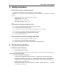
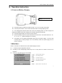
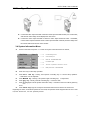
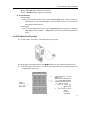
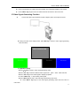
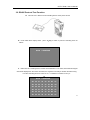
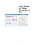
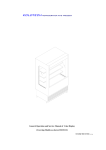
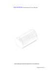
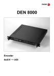
CCTV
User’s Manual
CCTV Tester User’s Manual
Content
1,
Safety Information.................................................................................................................1
1.1Precautions before using the tester ...............................................................................2
1.2Precautions during using the tester ...............................................................................2
1.3Precautions for battery charging and usage................................................................2
2,
Product Introduction ............................................................................................................2
2.1Features and Functions .....................................................................................................2
2.2Standard Item........................................................................................................................3
2.3Configuration Introduction................................................................................................4
2.4Specification .........................................................................................................................6
3,
Operation Introduction ........................................................................................................6
3.1Power and Battery Charging ............................................................................................7
3.2Main Menu .............................................................................................................................7
3.3Video Signal Test................................................................................................................8
3.4 System Information Menu ................................................................................................8
3.5 PTZ Test.............................................................................................................................9
3.6UTP Cable Test ...................................................................................................................10
3.7Video Generating Function .............................................................................................11
3.8 RS485 Protocol Test ........................................................................................................12
4,
Warranty ................................................................................................................................12
4.1 Warranty Items ..................................................................................................................12
4.2 Warranty exception ..........................................................................................................13
4.3 Complementary Clause...................................................................................................13
1
CCTV Tester User’s Manual
1, Safety Information
1.1Precaution before using the tester
A.
Make sure to read the user’s manual before using the products;
B.Make sure to check the supply accessories to confirm whether it is normal or not before
connecting ;
C.
Please use the product under the following conditions:
z Temperature:-30℃-70℃
z Relative Humidity:30%-90%
z Recharging Voltage:DC 9V-12V
1.2Precautions during using the tester
A.
Do not use the tester in humidity or leaking gas environments;
B.
Do not touch the tester with wet hands;
C.
Be careful not to shock or shake the tester during using it to avoid damage;
D.
Do not use it under the strong electromagnetism environment;
E.
Do not to expose the ports or connectors to dirt or liquid;
F.
Do not disassemble the tester.
1.3 Precautions for battery charging and usage
A.
Please use the original battery and charger matched;
B.
Please don’t connect the battery polarity wrongly;
C.
Please avoid battery short circuit and don’t dismantle it during working.
2, Product Introduction
2.1Features and Functions
A. Video Signal Test function
We can test the quality of picture from the video signal by connecting the tester and equipment
which is used to gather the images.
B. PTZ Controlling Test Function
It has the basic operational test of PTZ products :including P/T, zoom in/out, lens focus
adjustment, preset setting and preset call,rotation speed setting, aperture controlling and so
on. Meanwhile, it can support multi-protocol and baud rate, communication ports including
RS485,RS422, as well as RS232;
RS485 protocol include:Pelco D,P,Samsung,Panasonic,Minking , Vido, Yaan ,protocols
can be added as requested;
2
CCTV Tester User’s Manual
Baud rate include:2400,4800,9600,19200。
C. UTP Cable Test Function
Cable connecting condition and its sequence can be visible by using our cctv tester.
D. Video Signal Generating
The tester can create four different colors including Green, White, Black and Blue to help
technicians to inspect display equipment by outputting these video signal to the display, such as
monitors and DVR. The generating signal support PAL or NTSC (P and N can’t be supported at
the same time )。
E. RS485 Protocol Test Function
It can test RS485 data output from controlling device,display the communication content by
hexadecimal format on the screen. It is more convenient for technicians to analyze whether the
protocol is correct or not, or to analyze unknown protocol.
2.2Standard Item
Item
Quantity
CCTV Tester
1
3.6V Li Battery
2
UTP Cable Test
1
DC9V Power Supply
1
RS485 Connector
1
BNC Connect Cable
1
Lanyard
1
Middle-sized Crocodile
Clip
1
User’s Manual
1
3
CCTV Tester User’s Manual
2.3Configuration Introduction
Data Transmitting LED:
Data Receiving LED:
It lights during data transmitting
It lights during data receiving
Charge Indicating LED:
Power LED:
It is on when being charged, glitters
It is on when tester works
when finished
2.5 “LCD Screen:
Aperture on & Setup:
Resolution:960x240
Zoom in & enter into function mode
setup
Aperture off & Cancel:
Zoom out or cancel data setup.
Menu:
Function mode display area.
Tele:
Version no. & SN code display
To zoom in lens focus and send the
generated video signal
Shift
button setup:
Shift up, down, right , and left in the
Wide:
menu or during operation
To zoom out the lens focus and stop
sending generated video signal
0—9 Number key:
Preset setup or call,to adjust dome
Far:
address
,
enter
into
various
To adjust PTZ focus to far direction
function mode interface
Add.:
Near:
PTZ
To adjust PTZ focus to near
address setup
direction
Setup Preset:
Call Preset:
PTZ preset setup
PTZ preset call already setup
4
CCTV Tester User’s Manual
RS232 port
DC9---12V power jack
Video input
Video output
Power
Switch
UTP cable jack
RS485port
Battery slot
5
CCTV Tester User’s Manual
2.4Specification
Model
CCTV Tester
Video Signal Test
Signal Mode
Display
Video Input
Video Output
NTSC/PAL automatically suitable
2.5”LCD color screen, Resolution:960 x 240
1channel BNC insolated input
1channel BNC drive output
PTZ Controlling Test
Communication
Protocol
Baud Rate
Support RS232 bus, RS422 simplex and RS485 bus
Multi-protocol such as Pelco D,P ,Samsung, Panasonic,Minking,Vido,Yaan
and so on can be compatible
2400,4800,9600,19200
Other Function
UTP Cable Test
Video Signal
Generater
RS485 Data Test
Menu
Keyboard
Test each cable’s condition and connecting sequence can be displayed on
the screen
1 channel video signal can be output
receive and display the RS485 data sent from controlling device.
English OSD menu,character with frame can adapt white or black image, no
need to make any brightness adjustment
Top grade keyboard with waterproof, dustproof, and sun-shield option
Power
Power Adapter
Battery
Rechargeable
electricity-saving
function
DC9V---12V
2pcs 18490standard li batteries,3.6V/pc,capacity:1400mAh/pc
5hrs recharging time, can be used 5 hours after fully charged once
Low consumption, sleeping mode, battery capacity displayed
Other Parameter
Operation
Temperature
Operation
Humidity
Dimension
-30℃---+70℃
30%-90%
170mm x 99mm x 48mm
6
CCTV Tester User’s Manual
3, Operation Instruction
3.1 Power and Battery Charging
Notice: please insert the battery
A.
The power switch is located on the side of tester,turn it “on” to power on the tester;
B.
Turn the power switch to “ON” to reboot the tester when it is during sleeping mode.
C.
The charging time should be more than 5 hours, the charging LED is on when charged, the
charging LED glitters when finish charging and it will stop charging automatically.
D.
The fully charged battery can work for 5 hours at least;
E.
When the battery indicator in system information menu shows 25(the status shows:100,90,
75,50,25,5),please recharge it for use timely;
F.
The battery can be charged automatically when plug in Ex-power supply,it can be used
normally when it is being charged,and the electricity comes from power supply, but not
battery at this time.
3.2Main Menu
Power on the tester, we will enter into Function Mode Display as shows:
z
1-5 stands for 5pcs independent submenu
z
According to the corresponding Number key from 1-5 and press one of them to enter into its
submenu;
z
Version No. and S/N code can not be edited;
1 SYSTEM SETUP
——>
System information submenu
2 PTZ CONTROL
——>
PTZ controlling submenu
3 UTP CONSTRUE
——>
UTP cable test submenu
4 VIDEO GENERAY
——>
Video signal generating submenu
5 RS485 DATA CONSTRUE
——>
RS485 data test submenu
——>
Software version no./ tester SN code
VER:V1.09
S/N:08110910
7
CCTV Tester User’s Manual
3.3Video Signal Test
A. Connect the video output terminal of camera to video input terminal of tester, turn on the tester,
and then the video image can be displayed on the screen.
B.
Connect the video output terminal of camera to video input terminal of tester,meanwhile,
connect video output terminal of tester to video input terminal of monitor, then the image from
the camera will be also shown on the monitor.
3.4 System Information Menu
A.
Power on the tester and press “1” to enter into System Information Menu as follows;
PROTOCOL
Pelco P
——>
PTZ Controlling Protocol
COM
485
——>
Communication port
RATE
4800
——>
Baud rate:2400/4800/9600/19200
SPEED
016
——>
PTZ rotation speed
IDLE TIME
000
——>
Time from “no operation” to “idle mode”(minute)
BATTERY
090
——>
Batter power status:100/90/75/50/25/5
B.
Press “Set” key to start setup operation:
C.
Press“2”or “8” key(namely, PTZ up/down controlling key)to choose setup operation.
(”BATTERY” can’t be adjusted);
D.
Press“2/6/8” key(namely ,PTZ up/down /right controlling key) to adjust data;
E.
Press“4” key(namely ,PTZ left controlling key)to save the data;
F.
Press“4”key again to finish System Information Setup.(character in the menu will not glitter any
G.
Press ”Menu” key longer to exit System Information Submenu and back to the main menu
more);
Regarding our tester, we devide its speed into 16/7 levels, the operation will be stopped when the mini. Level
is 0; Max. level is 16/7 , it is max. speed of protocol.
8
CCTV Tester User’s Manual
3.5
PTZ Test Function
A. Equipment Connection
z Connect the tester with the PTZ cameras as picture shows;
z Under the main menu display status, press“2”key to enter into PTZ Controlling
Menu as follows:
PTZ
Add.
code
<——
ADDRESS:001
VIDEO:NULL
——>
001-255
Camera video format
PAL/NTSC/NULL
B. Operation setup
z
Press “Add.” key,input PTZ address to be controlled or change PTZ address.
z
Press ”Set” key to save data.
z
Press “Menu” key to hide PTZ controlling function menu.
z
Press “Menu” key longer to return “Main Menu”.
C. PTZ Controlling
When we connect PTZ to our tester correctly, the camera image will be displayed on the
screen; when we set up protocol, baud rate, and corresponding PTZ address through “System
setup menu” , you can choose to hide “PTZ controlling function menu” or not yourself, and then
to control PTZ according the following methods:
z Press up/down/left/right key to control PTZ rotation direction;
9
CCTV Tester User’s Manual
z Press “Aperture On/Aperture Off” key to open or close it;
z Press “Near/Far” key to adjust focus manually.
z Press “Tele/Wide” key to adjust focus manually.
D. Preset Position
z Preset Setup:
During PTZ controlling function mode,press “Preset Setup” key,input the number to
adjust preset no., and press “Set” key to confirm operation. Preset no. can be setup by
the method mentioned above;
z Call Preset:
During PTZ controlling function mode,press “Call preset” key , input preset no. and press
“Set” key to confirm operation,
“Call preset” can be setup by the method mentioned
above;
3.6 UTP Cable Test Function
A.
Connect tester-UTP cable-UTP tester as the picture shows:
B.
During Main menu display status, press“3”key switch to UTP cable test operation mode;
C.
Press ”Set” key to start the test,UTP cable connection status and connecting sequence will
be displayed on the screen;
UTP CABLE TEST
Cable
sequence
on
cctv
tester end
<——
3----3
6----6
--- 1----1
--- 0----0
--- 0----0
--- 2----2
--- 7----7
1
2
3
4
5
6
7
---
8
---
——>
---
8----8
——>
——>
Cable sequence on UTP
tester end
(double time confirmation)
“0” means disconnection
If there are two lines shows
“0” state, it means:
1、 Both of them are
disconnecte
d;
2、 The 2 lines are short
circuit
between
each other;
10
CCTV Tester User’s Manual
D.
Users can estimate UTP cable connection situation from information display on the screen.
E.
Press “Menu” key longer to exit UTP cable test mode and return to the main menu.
3.7Video Signal Generating Function
A.
Connect the video output terminal of tester to display device as the picture shows:
B. During the main menu display status, press“4”key to switch to video signal generating
mode as follows:
VIDEO GENERATING
C. Operation setup
z Press“4”key to switch to video signal generating mode;
z Press ”Set” key to switch to different video signal color:green,white,black and blue;
z Press ”Tele” key to send video signal to display equipment;
z Press “Wide” key to stop sending video signal;
z Press “Menu” key to hide or call video signal generating mode menu;
z
Press “Menu” key longer to exit video signal generating mode menu and return to
main menu.
11
CCTV Tester User’s Manual
3.8 RS485 Protocol Test Function
A. Connect CCTV Tester to PTZ Controlling device as the picture shows:
B.
Under Main Menu display status,press“5”key to switch to protocol controlling menu as
follows:
DATA CONSTRUE
C.
Make the PTZ controlling device transfer the RS485 data to cctv tester, the hexadecimal signal
data will be displayed on the screen as follows, the engineers can analyze whether the data coming
from the controlling device is correct or not , or whether it is needed or not by it.
z
DATA CONSTRUE
A0 00 01
00 00
00
AF 0F
A0 00 00
00 00
00
AF 0E
A0 00 00
01 00
00
AF 0F
A0 00 01
00 00
00
AF 4F
A0 00 00
00 00
00
AF EF
A0 00 00
00 00
00
AF 2F
12
CCTV Tester User’s Manual
4,
Warranty
4.1 Warranty Items
Since the delivery day:
1) Exchanging service within 7 days from the receiving day, we will be responsible for the freight
charge (battery exchanging service within 90 days from the receiving day).
2) Repairing service within 2 years, change accessories and repair for free, customers should be
responsible for the freight charge (repairing service don’t include battery).
3) We provide whole life repairing service for our products with proper charge, customers should
be responsible for the freight charge.
4.2 Warranty Exception
We provide repairing service with proper charge, customers responsible for
the freight charge
1)
Damage caused by abuse, unreasonable use, mistreatment, or neglect.
2)
Damage caused by modification or repair not authorized by our company, working in hostile
environments, or natural disaster.
3)
Damage caused by improper or improperly used packaging, or other devices work in the same
system.
4.3 Complementary Clause
1)
Company is not responsible for other assurance and other derivative from capital loss: The
product and the user guides are not assured for particular users and some special purpose of
use.
2)
If the products returning for exchanging was damaged, modified or miss accessory, we will
charge the proper payment.
3)
If the components are no longer produced during the warranty-limited period, company will
make a decision to replace similar products at no charge.
13