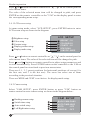
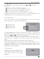
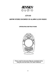
1
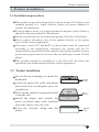
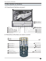
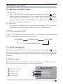
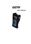
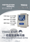
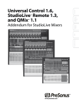
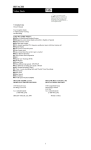
IN-DASH CAR LCD MONITOR
USER'S MANUAL
Ã
Please read this manual carefully before using this product
and properly keep the manual for future use.
Contents
Contents
1. Brief introduction------------------------------------------------------------ 02
2. Product features-------------------------------------------------------------- 02
3. Product installation---------------------------------------------------------- 04
4. Description of buttons
4.1 Function of buttons on panel --------------------------------------------- 06
4.2 Function of buttons on remote control ---------------------------------- 06
4.3 Description of functional buttons on the panel ------------------------- 07
4.4 Description of functional buttons on the remote control-------------- 07
5. Product system operation
5.1 Turning on/off system--------------------------------------------------- 08
5.2 Video modes switch------------------------------------------------------ 08
5.3 Angle adjustment--------------------------------------------------------- 08
5.4 Menu setup---------------------------------------------------------------- 08
6.AV function-------------------------------------------------------------------- 1 1
7.CAM function----------------------------------------------------------------- 1 1
8. Accessories(optional)-------------------------------------------------------- 12
9. Precautions-------------------------------------------------------------------- 15
10. Trouble shooting------------------------------------------------------------ 15
11. Packing list ------------------------------------------------------------------ 16
Safety statement
Safety statement
It is prohibited by law in some countries to watch TV or other programs or
do relevant operations while driving. For your safety, please do not watch
any programs or do any associated operations during driving.
As for car backing system, it works simply as an assistant tool. Our
company is not responsible for any potential car backing accidents.
! WARNING
Since this player is a very complicated electronic and mechanical device,
please do not dismantle it any parts at will, so as to avoid damaging the
player .
This player contains precise electronic mechanism. Please do not apply
external force on it when it is stretching out or drawing back, turning or
halted, in case the mechanism may be damaged.
! NOTE
Due to technical improvement, specification and design are subject to
change without notice.
1
Brief introduction/Product features
1. Brief introduction
Thank you for purchasing this kind of high quality car entertainment product.
This kind of product is a new multi-functional system . It applies imported
TFT module incorporating with advanced microprocessor technology,
sophisticated optimizing design, and built-in anti-interference and noise
reduction circuits, and it is provided with features such as high resolution,
flicker free, radial free, low power consumption, reliable and green
environment protection. The monitor can be concealed automatically, which
fully meets the moderns' requirements of small, precision and concealment.
This is a professionally designed vehicular electronic product in intelligent
operations mode. It is provided with OSD menu display, in which you can
use panel buttons to perform operations such as color and brightness
adjustment. You can also use remote control to complete these functions to
realize the interaction between user and the machine friendly. All the
adjusted parameters and positions can be memorized and restored
automatically, providing you with the easiness and convenience you want. It
provided multiple video inputs(including rearview camera) and AV output
for playing video and monitoring. The wide voltage range design can meet
the requirements of various types of cars. In addition, this series of products
provides various functions and accessories such as car-backing sensor and
camera. In order to protect your interest, please carefully check the
corresponding packing list according to the specifications of the product
you purchased. Please read this manual carefully for the correct installation
and operation of this product.
2. Product features
2.1 Product specifications
Item
Specification
Working voltage
DC 12V
Working current
MAX 1.5A
Working temperature
20~60 oC
Storage temperature
30~80 oC
Video System
Auto PAL or NTSC
2
Product features
Specification
Item
Input Configuration
External Dimension
Internal Dimension
Weight
Screen Dimension
Resolution
Pixel dot Pitch
3-channels video input
(Including car backing camera input)
17.8(W) 20.2(L) 5(H) cm
17.8(W) 18(L) 5(H) cm
2.0 Kg
7 inches (diagonal)
1440(H) 234(V) pixel
0.107(H) 0.372V)mm
Video output
1
Video system
NTSC (default) or PAL
0.2Vpp
2.2 Product functions
Auto Memory:
All the adjusted parameters and positions can be
memorized and restored automatically.
Display system
PAL or NTSC automatically provided with wide
range of application and strong compatibility.
Remote control:
Full function remote control provides you extra
easiness and convenience.
Menu function
All the operations are displayed in OSD menu, and
also display real time.
Signal selection
3-channel signal input and 1-channel AV output for
convenient connection of external signals.
Car-backing detecting: Specially built-in car reverse video input, while
backing the car, display will automatically change
to the rearview lens to display car backing status .
Mode selection:
3 preset video modes: bright, standard and soft for
fast and convenient pictures quality adjustment.
Display mode:
2 available display modes, wide and standard screen.
Protection mode:
The screen in-out process is provided with hitch
automatically inspected functions.
2.3 Product application
Adopted the super thin, high resolution and wide screen TFT LCD display
module, together with built-in TV, amplifier circuits and loudspeaker, this
kind of products have the features of easy installation, simple connection,
radial free, low power consumption, radiation free, wide viewing angle,
vibrant true color and compactness. It can be extensively applied to areas
that need monitoring, entertaining or displaying, and also to various special
cars, sedans and luxury buses.
3
Product installation
3. Product installation
3.1 Installation procedure
This product is specially designed for vehicles using a 12V battery with
common ground. For other vehicles, please use power adapter or
consult the distributor.
To avoid short-circuit, it is suggested that the negative pole of battery
should be disconnected before installation.
Do not override the fuse to connect this product directly to the battery.
Never connect the power wire of this product directly to the power
wire of other electric appliances.
The power cords ACC and BATT of this product must be connected
according to the instructions, otherwise the system will not be
automatically turned off after the engine is shut down, and thus causing
great battery power lost if you leave the car and forget to turn off this
player.
This product should be installed in a slot that will not affect the
operation of air conditioning and other electric appliances.
3.2 Product installation
Be careful not to damage or smear the
dashboard.
Locate an empty slot in the instrument
panel and clear up adequate space for
installation.
Take out the internal casing and install
it into the slot.
Install the player and connect the
power cord and video cords, and then
insert the player into the slot.
Cover the external casing onto the
player .
Internal
Casing
Main
Machine
External
Trim
4
Product installation
3.3 Battery replacement
Take out the battery seating, press and hold
the clip, and pull the battery seating out.
Replace the battery, place the battery into
the battery seating with positive (+) pole
facing upward.
Insert the battery seating, and push it into
the original position.
Back of Remote Control
Battery seating
Battery +
Battery Clip
! NOTE
Fault battery should be replaced immediately. Abandoned batteries should be
dispose into battery-kind garbage box.
3.4 Production connection
Connect the power cord ACC (red) to the ignition switch.
Connect BATT yellow to battery circuit positive .
Connect car backing cord blue to car backing switch or car backing
circuit (for 12V only).
Handbrake control wire is effective at low voltage level.
Connect the video signals to video input ports.
Connect camera.
Connect Rear sensor.
Connect AV output.
Make sure that everything is correctly connected, and coordinate all
the cords for easy installation.
3.5 System connection diagram
Blue
Black
GND
Red
ACC
Car backing signal
Yellow
BATT
Video input(Yellow)
Backing sensor input
CAM1 input
Handbrake GND black
Handbrake wire(P) purple
CAM2 input
5
Video output(Yellow)
Player
Car backing control is active
at high voltage level.
Hand brake control is active
at low voltage level.
Description of buttons
4. Description of buttons
4.1 Functions of buttons on panel
Angle adjust(+)
Angle adjust(-)
Reset
AV switch
Remote sensor
Power switch
Video mode button
Station selcet/adjust(-)
1
Menu button
Menu select
Station selcet/adjust(+)
Menu select
CAM1/CAM2 switch
4.2 Functions of buttons on remote control
CAM1
CAM2
CAM1
Sector
TV
CAM2
0
AV
1
2
3
4
5
6
7
8
9
Angle adjust(-)
1
AV
Angle adjust(+)
Menu select(+)
Menu button
Power switch
etup
V-mo
d
MEM
Seek
Auto
OSD
CLK
Mute
e
S
Menu adjust(-)
Menu select(-)
CAM auto switch
Clock display switch
Video mode
Menu adjust(+)
Enter button
Input status display
Remote control
6
Description of buttons
4.3 Description of functional buttons on the panel
Reset :All the adjusted parameters will be lost when you recover to the
manufacturing setting .
AV button: To switch to AV play.
CAM1/CAM2 button: To switch to between CAM1 play and CAM2 play.
" and "
" button can adjust the
Menu adjust-/+: In menu mode, "
parameter.
Power switch: Turn on/off the player, or make the screen turn backward
or forward.
Menu select: In menu mode, " " and " " button can adjust the up and
down direction.
Menu button: Turn on or turn off the menu .
Video mode: To switch video mode among Standard, brightness, softness,
custom in turn.
11 Remote sensor: Infrared ray remote control receiving window.
12 13 Angle adjust-/+: for an opened display, used to reduce or increase
decline angle for screen.
4.4 Description of functional buttons on the remote control
14
15
16
17
CAM1: Switch to CAM1 status.
CAM2: Switch to CAM2 status.
AV: Switch to AV status.
18 Angle adjust-/+: for an opened display, used to reduce or increase
decline angle of screen.
19 26 Menu select+/-: used as Up/Down buttons at menu mode.
20 Power switch: To switch ON/OFF power and display, or make the
screen turn backward or forward.
21 Menu button: Turn on/off the menu.
22 Video mode button: To switch video mode among standard, bright, soft,
and user setting.
23 24 Menu adjust-/+: To adjust item parameter at menu mode.
25 Enter button: Enter into menu or return to main menu.
27 Input status display button: Display the current status.
28 CAM auto switch button: CAM1/CAM2 auto switch, turn on or off
function.
29 Clock display switch: Turn on/off the clock.
7
Product operation
5. Product operation
5.1 Turning on/off the system
A. Switch on
Press the " POWER " to button on the control panel or the " " on the
remote control and the LCD will be drawn out with the latest mode.
Press once more " POWER " on the control panel or the " "on the
remote control, the LCD will be withdrawn back to the compartment
and enter into the waiting mode.
B. Switch off
The power is switched off 3 seconds after switching ACC, the screen
automatically withdraw back and the power of system turn off.
5.2 Video modes switch
Press "V-M" button on remote controller or "V-MODE"on panel to switch
the video display modes in turns as given below:
STANDARD
BRIGHTNESS
SOFTNESS
CUSTOM(USER'S SETUP)
5.3 Angle adjustment
The incline angle of the screen can be adjusted by pressing
or
button
on remote controller or on panel when the screen is at ON status. The system
will store automatically the preset angle when the system is switched OFF
normally.
5.4 Menu setup
Menu can be turned on or off by pressing Setup button or
the control panel when the power is ON as given below:
LCD screen setup
Camera setup
System setup
Clock adjust
SET button on
USER SETUP
LCD SETP
CAM SETUP
SYS SETUP
CLOCK ADJ
8
Product operation
Press
or button on remote controller or " "," " on the control panel to
select menu items.
The color of the selected menu item will be changed to pink, and press
ENTER on the remote controller or the " V-M " on the display panel to enter
the corresponding menu setup.
5.4.1 LCD screen setup
At menu setup mode, select "LCD SETUP", press ENTER button to enter
LCD screen setup as shown in the diagram:
Brightness setup
Color setup
Contrast setup
Display position setup
Display mode setup
LCD SETUP
BRIGHT :32
COLOUR:22
CONTR :25
ANGLE :30
STATION:1
VIEW :WIDE
V-MODE
:WIDE
Press or button on remote controller or " "," " on the control panel to
select menu items. The color of the selected item will be changed to pink.
Press
and
button on remote controller to adjust setup parameters and
to store automatically. Press ENTER button on the controller or the V-M on
the control panel to return back to previous menu status.
There are 0, 1, 2, 3 preset positions for horizontal positions of screen (0 is
the first one, and 3 is the last one). The users can select one of them
according to the practical situation.
There are WIDE and CENT two choices for display mode setup.
5.4.2 Camera setup
Select "CAM SETUP", press ENTER button or press "V-M" button on
remtoe control to enter camera setup as shown in the diagram below:
Backing camera setup
Switch time setup
Auto switch setup
Left/Right mirror setup
9
CAM SETUP
BACK CAM:CAM1
AUTO TIME:6SEC
AUTO
:OFF
MIRROW :OFF
Product operation
Press
or button on remote controller to select menu items. The color of
the selected item will be changed to pink. Press
and
to adjust the
parameters.
There are CAM1 and CAM2 for selection.
There are 3, 6, 9, 12, 15 Seconds TIME for selection.
There are OFF and ON for CAMERA selection.
There are OFF and ON for CAMERA IMAGE selection.
The adjusted and preset parameters will be stored automatically. Press
ENTER button or V-M to return back to the previous menu.
5.4.3 System setup
Select "SYS SETUP", and press ENTER button to enter system setup at
menu setup mode as shown in the diagram below:
Button beep setup
Time display setup
Backing view setup
SYS SETUP
BELL :ON
TIME OSD :ON
BACK VIEW:ON
Press
and
button on remote controller or press" " ," " button on
panel to select menu items and the color of the selected item will be changed
to pink. Press
and
to adjust the setup parameters.
The setup parameters will be stored automatically. Press ENTER button on
remote control or " V-MODE" on the panel to re turn back to the previous
menu.
Sound will be given when pressing buttons if BELL setup is on.
Clock will be displayed on lower right side of screen if the time OSD is on.
When BACK VIEW is ON, it will switch automatically to rear view mode
(equipped with backing camera or sensor) while backing. Otherwise, the
BACK VIEW will be turned off.
5.4.4 Time setup
At menu mode, select "CLOCK ADJ" or
V-M and press ENTER button to enter
Time setup as shown in the following
diagram:
YEAR MON DAY HOU MIN
2005
01
01
12
00
10
Product operation/AV function/CAM function
Press
and
button on remote controller or press " " ,"
" button on
panel to select setup items, and the color of the selected item will be
changed to pink. Press
and
to adjust the setup parameters.
Press ENTER button on remote control or press"V-M" button on panel to
store t he setup parameters, and return to the previous menu. Press SETUP
button on remote control or press SET button on panel to exit directly
without saving.
6. AV function
It will switch to AV mode by pressing AV button on remote controller or AV
button on panel.
7. CAM function
Press CAM button on panel or CAM1, CAM2 on remote controller to switch
to camera input mode.
It is available to carry out setup in accordance with the requirements at
camera mode, e.g. fixed at CAM1 or CAM2, switch between CAM1 and
CAM2. It is also available to set up functions such as the switch time,
backing camera, auto switch, mirror image, etc. in CAM menu .
11
Accessories(optional)
8. Accessories(optional)
As a series product, there are different functions and accessories for
different products according to their technical specifications such as review
sensor, backing camera, etc. To assure users interests, please check carefully
the corresponding packing list of product in accordance with the product
specifications purchased.
8.1 Installation of backing sensor
8.1.1 Sketch diagram of detection range for sensor probe
Instant Stop Area
Buffer Area
Alert Area
8.1.2 Sensors ' installation position
30-35cm
30-35cm
50-70cm
60-80cm
According to the quantity installed, the positions can be as follows
25cm 25cm
63cm
2 probes
63cm
4 probes
! NOTE
The final installation position can be adjusted slightly according to your
car dimensions.
12
Accessories(optional)
8.1.3 The requirements and method of installation
Sensors should be inserted vertically into rear bumper as the arrow's direction.
Any direction's inclination will affect the usage.
Vertical
Horizontal
8.2 Backing sensor usage
If backing car signal cable is connected properly, rear sensor will function
automatically while backing your car.
8.2.1 Signpost display
When the backing car module is not
connected, monitor will display
BACK (yellow) while backing, which
as shown in right picture.
-BACK-
When the backing car module is
connected only to left or right sensor,
while backing, monitor will only
display left or right radar signposts,
on the other side is only ordinary
signpost.
When the backing car module is
connected both the left and right
probes, monitor will display both left
and right radar signposts as the right
picture.
13
0.8M
-BACK-
0.8M
-BACK-
Accessories(optional)
8.2.2 Display of radar detection
When the distance between radar sensor and barrier is more than 1.6m,
" FAR" will be displayed on screen bottom.
When the distance is less than 1.6m but more than 1.2m the distance
will be displayed on screen bottom, buzzer does not work, and the
sensor is now working in warning area.
When the distance is less than 1.2m but more than 0.2m the distance is
displayed on the screen bottom, and buzzer beeps. The more closer, the
more frequent buzzer beeps. Sensor is now working in slow down area.
When the distance is less than 0.2m it will display "STOP!" On
screen bottom buzzer gives out continuous sound and sensor is now
working in stop area.
! WARNING
When radar signpost is available the more decreasing distance
between radar sensor and barrier becomes, the more red signpost goes
down. When the distance increases, green signpost goes upward.
System takes out the data of four radar sensors, after calculation, the
Shortest distance will be displayed on top of screen.
8.2.3Precautions
! NOTE
The system is only designed to help you back your car our company
will not take any responsibilities for any accident. Please do pay more
attention during driving.
Detection can be affected by:
When on some smooth slopes, signal
will be reflected out.
When near some smooth spherical
object, signal will be reflected out.
Smooth
Smooth global object
When near some cotton like object
which will absorb sound , signal will
be absorbed greatly.
After installation, before using, please
first confirm the function.
Cotton like object which
will absorb sound
14
Precautions/Trouble shooting
9. Precautions
Don't operate this product during driving.
Don't insert coins or some little things. Screws and other metal things
should be kept far away from the mechanism and discs.
Please don't try to repair. This player is composed of lots of precise
electronic components. They'll be broken or cracked if disassembled or
refitted. If there is something wrong, please turn off the power
immediately and notify distributor.
Please don't put the display screen on the pollution environment like
dampness, dust, stream, lampblack, etc.
Please don't use thinner or other chemical cleaner to wipe the surface of
the display screen. The dirt should be wiped off by using soft cloth.
Please don't keep the display screen dispose on the sunlight long .
If water or other substances have put into the product carelessly, please
turn off the power immediately and contact the distributor.
Please turn off the power first while cleaning the machine.
The working temperature of this product is 20 oC~ 60 oC .
The product is specially designed for vehicle, which is equipped with a
12V Accumulator with its cathode grounded.
10. Trouble shooting
Before sending this player for repairing service , please carry out inspection
or small adjustment according to possible causes of occurred problems
stated on the list below, and it is possible solve the problems. If you have any
doubt about the method on the following list, or the problem can't be solved
effectively by following the remedy as instructed, please contact our
company or professional repairing service centre.
! NOTE
This player is a very complicated mechanism. Please do not dismantle it and
try to repair it by yourself, in case that the mechanism may be damaged!
15
Trouble shooting/Packing list
Possible cause
Problem
LCD screen no
any display
Operation
failure
The power switch and igniting
switch are not switched on.
Solution
Set the switches to ON.
Connection wire is loose
Reconnecting
Fuse is burnt out
Replace with new fuse.
The functions are locked
Place a sharp object directly
into reset hole. Apply gentle
pressure to do reset
operation.
11. Packing list
1
Main unit
1 set
2
Remote controller
1 pc
3
Hand brake control wire
1 pc
4
Power input wire
1 pc
5
Camera
Optional
6
Rear sensor
Optional
7
Battery of remote controller
1 set
8
Tools of drawing out the main unit
1 pc
9
Accessories of main unit (screw,etc)
1 set
10
Internal casing of main unit
1 pc
11
External trim of main unit
1 pc
12
Manual
1 copy
16