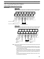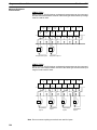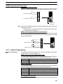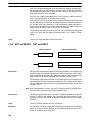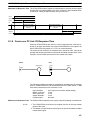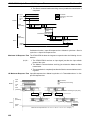
1
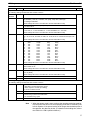
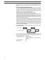
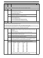
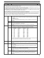
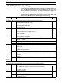
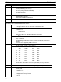
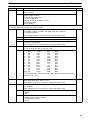
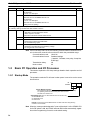
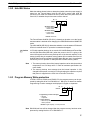
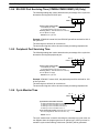
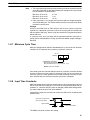
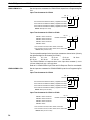
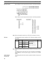
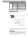
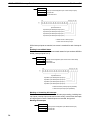
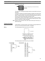
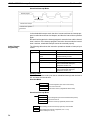
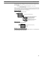
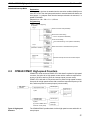
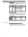
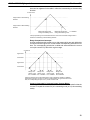
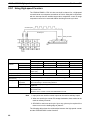
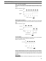
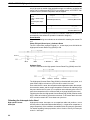
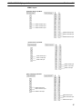
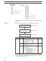
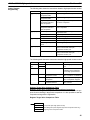
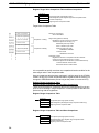
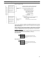
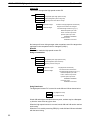
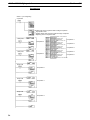
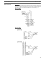
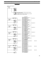
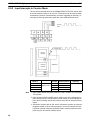
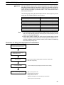
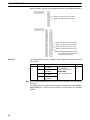
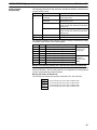
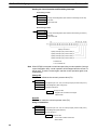
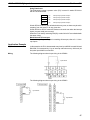
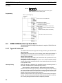
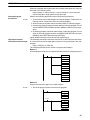
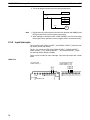
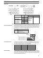
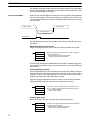
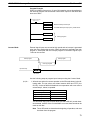
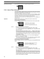
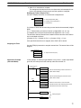
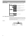
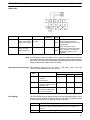
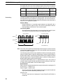
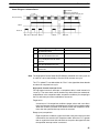
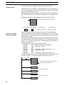
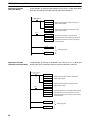
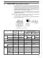
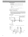
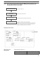
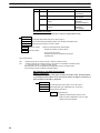
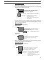
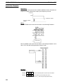
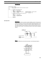
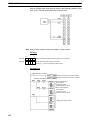
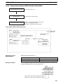
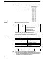
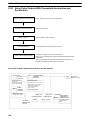
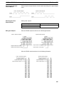
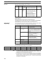
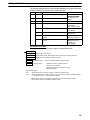
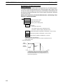
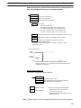
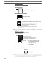
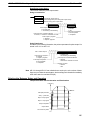
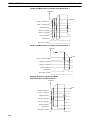
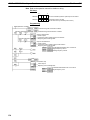
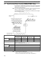
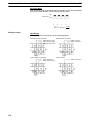
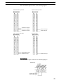
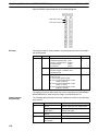
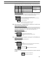
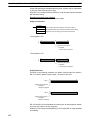
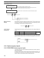
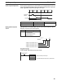
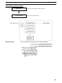
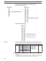
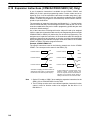
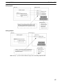
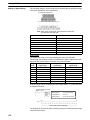
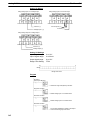
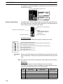
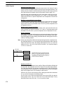
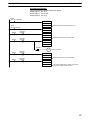
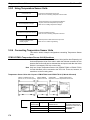
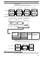
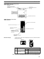
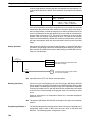
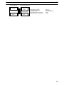
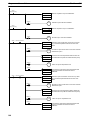
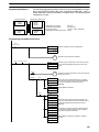
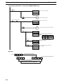
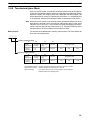
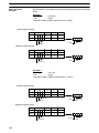
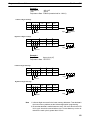
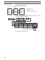
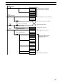
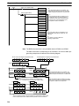
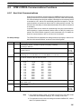
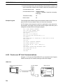
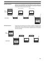
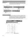
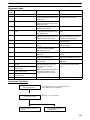
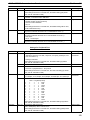
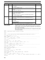
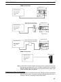
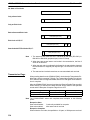
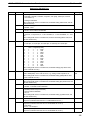
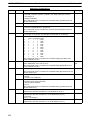
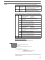
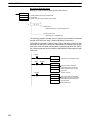
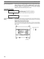
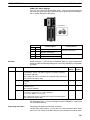
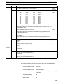
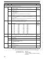
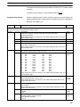
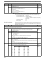
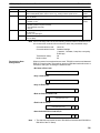
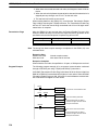
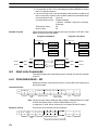
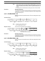
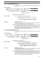
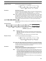
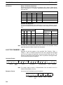
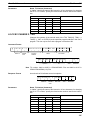
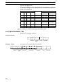
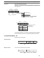
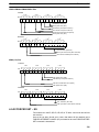
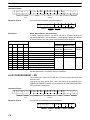
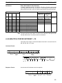
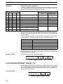
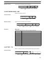
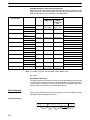
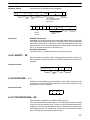
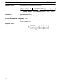
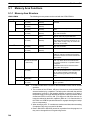
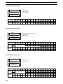
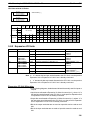
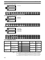
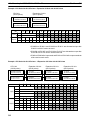
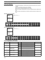
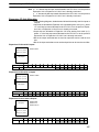
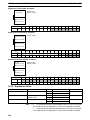
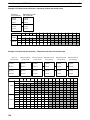
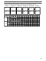
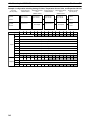
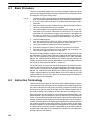
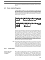
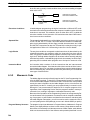
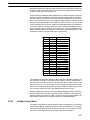
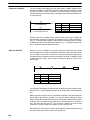
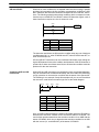
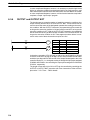
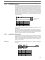
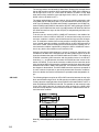
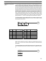
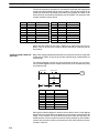
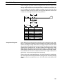
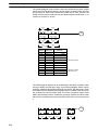
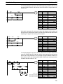
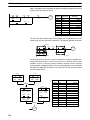
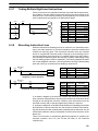
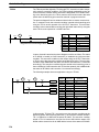
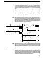
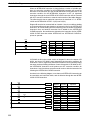
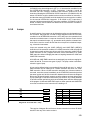
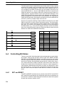
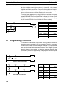
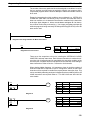
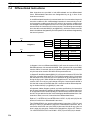
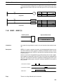
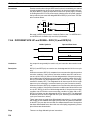
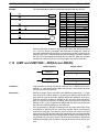
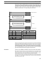
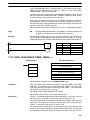
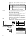
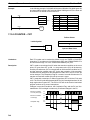
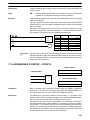
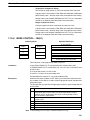
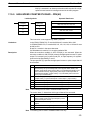
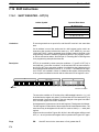
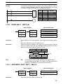
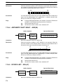
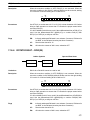
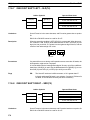
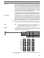
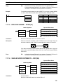
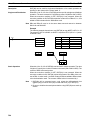
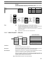
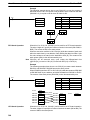
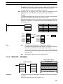
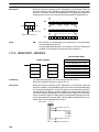
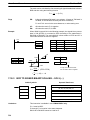
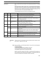
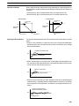
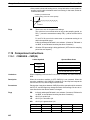
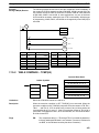
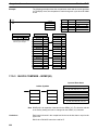
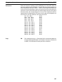
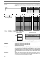
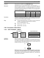
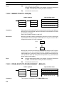
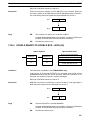
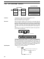
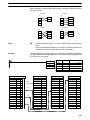
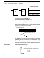
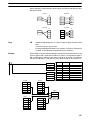
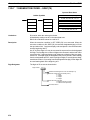
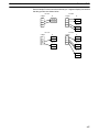
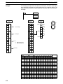
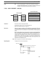
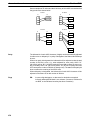
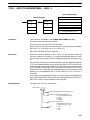
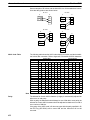
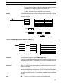
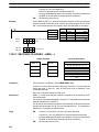
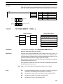
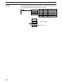
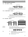
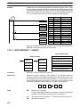
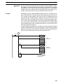
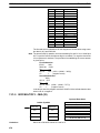
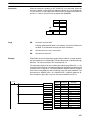
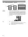
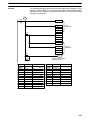
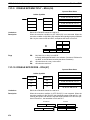
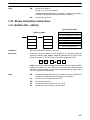
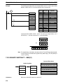
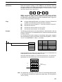
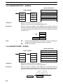
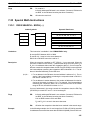
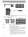
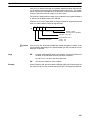
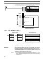
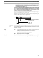
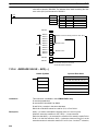
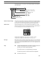
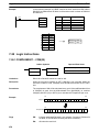
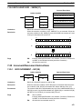
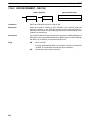
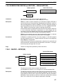
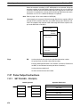
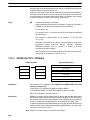
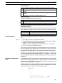
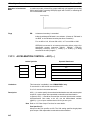
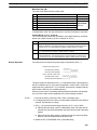
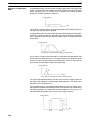
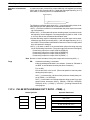
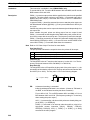
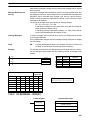
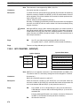
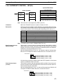
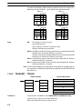
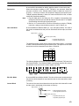
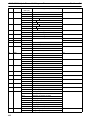
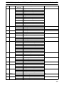
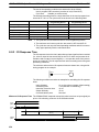
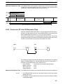
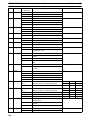
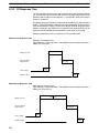
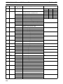
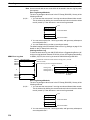
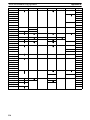
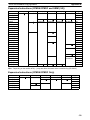
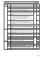
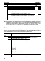
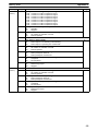
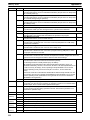
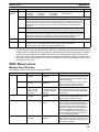
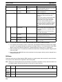
Section 7-30
Communications Instructions
The order in which data is written to memory depends on the value of digit 0 of C.
Eight bytes of data 12345678... will be written in the following manner:
Digit 0 = 0
MSB
D
1
D+1
3
D+2
5
D+3
7
Flags
ER:
LSB
2
4
6
8
Digit 0 = 1
MSB
D
2
D+1
4
D+2
6
D+3
8
Digit 0 = 2
MSB LSB
D
1
D+1
2
3
D+2
4
5
D+3
6
7
Digit 0 = 3
MSB
D
1
D+1
2
D+2
4
D+3
6
LSB
1
3
5
7
LSB
3
5
7
The settings in C are not correct.
N is greater than 256.
The PC Setup is not set for no-protocol mode.
RXD(47) is already being executed.
AR 08: AR 0806 will be turned ON when data has been received normally at the
RS-232C port. Reset when RXD(47) is executed.
AR 0814 will be turned ON when data has been received normally at the
peripheral port. Reset when RXD(47) is executed.
AR 09: Contains the number of bytes received at the RS-232C port. Reset to
0000 when RXD(47) is executed.
AR 10: Contains the number of bytes received at the peripheral port. Reset to
0000 when RXD(47) is executed.
Note Communications flags and counters can be cleared either by specifying 0000 for
N or using the Port Reset Bits (SR 25208 for peripheral port and SR 25209 for
RS-232C port.)
7-30-2 TRANSMIT – TXD(48)
Operand Data Areas
Ladder Symbols
S: First source word
TXD(48)
@TXD(48)
S
S
C
C
N
N
IR, SR, AR, DM, HR, TC, LR
C: Control word
#
N: Number of bytes
IR, SR, AR, DM, HR, TC, LR, #
Limitations
478
This instruction is available in the CPM2A/CPM2C and SRM1(-V2) only.
S and S+(N÷2)–1 must be in the same data area.
DM 6144 to DM 6655 cannot be used for S or N.