1
目录 PRECAUTIONS ...........................................................................................................................4 SAFETY GUIDE...........................................................................................................................5 OPERATOR ..................................................................................................................................6 DECLARATION OF EXCEPTIONAL RESPONSIBILITY................................................6 1. NAME OF EACH COMPONENT & ITS FUNCTION ...................................................8 1.1 Name of Each Component......................................................................8 1.2 Operation Keys & Functions ................................................................10 1.3 Display..................................................................................................11 1.4 Symbols ................................................................................................12 2. PREPARATION FOR MEASUREMENT.......................................................................13 2.1 Mounting the Instrument ......................................................................13 2.2 Power On ..............................................................................................15 2.3 Remaining Battery Display...................................................................15 2.4 Setting the record mode ........................................................................16 2.5 SD Card ................................................................................................18 2.6 Menu.....................................................................................................18 2.7 SET .......................................................................................................19 2.8 Inputting Characters..............................................................................19 2.9 Staff Collimation and Focus .................................................................21 2.10 Surveying Note ...................................................................................22 3. STANDARD MODE ............................................................................................................23 3.1 Measure ................................................................................................23 3.2 S.O G.H( Stake out Ground Point)........................................................26 3.3 S.O H.D(Stake out Height Difference) .................................................29 3.4 S.O Dist(Stake out Distance) ................................................................31 4. LEVELING.............................................................................................................................34 4.1 Start Leveling........................................................................................34 4.2 End the Leveling Measurement on the Transition Point.......................66 1
4.3 End the Leveling Measurement on the Bench Mark Point ...................68 4.4 Continue Leveling ................................................................................70 5. OTHER FUNCTIONS.........................................................................................................72 5.1 Manually Inputting Data Key—[MANU] ............................................72 5.2 Display the Distance—[DIST]..............................................................74 5.3 Inverse Staff Mode—[-]........................................................................74 5.4 Record Data Search—[SRCH] .............................................................75 6 HORIZOTAL ANGLE MEASUREMENT .......................................................................79 7. FORMAR FLASH OR SD CARD .....................................................................................81 8. DATA MANAGE...................................................................................................................84 8.1 Create Group.........................................................................................86 8.2 Search Job.............................................................................................87 8.3 Copy Job ...............................................................................................88 8.4 Delete Job .............................................................................................90 8.5 Check the Capacity of Flash or SD Crad ..............................................91 8.6 File Out .................................................................................................92 9. SET ..........................................................................................................................................94 9.1 Set Menu...............................................................................................94 9.2 Alter the Setting Mode..........................................................................97 10. BATTERY AND CHARGER ...........................................................................................99 10. ADJUSTMENT ............................................................................................................... 100 10.1 Method A ..........................................................................................100 10.2 Method B ..........................................................................................104 11. TRANSPORTATION, STORING AND CLEANING.............................................. 104 12. SPECIFICATION............................................................................................................ 106 2
FOREWORDS
Congratulations on your purchasing the Digital Level DL-201/2007. In order to
operate this instrument correctly, please read this user manual carefully and keep it
well so as to refer to it easily in the future. Before use, please check the standard
features and make sure all the equipments and accessories are available.
In order to facilitate reading, some pictures are simplified.
3
PRECAUTIONS
Before using this instrument, please make sure that each function is running well.
●Avoid to make the surface of the digital staff as well as the joints between each
section dirty or damaged, otherwise it will influence on the accuracy of reading and
measurement. This is because the instrument needs to transfer the black & white bar
code to electric signal. That’s why in case the digital staff is dirty, the accuracy would
be descended, or even the instrument is not able to measure.
●Tripod
The digital level should be mounted on wooden tripod. Metal tripod is lighter and
shack easily, which will affect the accuracy. Each leg of the tripod should be fixed well
by screws.
●Tribrach
Please check the adjusting screw on the tribrach frequently, do make sure the central
fixing screw is tightened.
●Packing well to avoid the instrument shaked
The digital level should be handled carefully to avoid shaking and crashing during
transportation. Severe shaking would damage the measurement functions. When
packing the instrument in the case, make sure the instrument is power off and take off
the battery too.
●Carry the instrument carefully
When you need to move the instrument, you must grasp the lifting handle and take it
off from the tripod.
●Avoid to expose the instrument in sun, rain or humid condition
Leaving the instrument in place of high temperature (+50℃) would damage the
instrument. Do not shoot the sun with the objective len; otherwise the spare parts
inside the instrument may be damaged.
●Avoid the great change of temperature
A great change on instrument temperature would descend the measuring range. For
example, when the instrument is moved out from a hot car, please leave the
instrument to adapt to the surrounding temperature before use.
●Battery Inspection
Check the remaining battery before use.
4
●Digital Staff
Wear a glove when using a digital staff.
SAFETY GUIDE
Serious injury or even death may occur if the following cautions are ignored.
●In case of explosion, do not place the instrument close to inflammable gas, liquid, or
solid. Do not operate it in coal mine or dusty place.
●Do not disassemble or repair the instrument without authorization in case of
dangers like fire, electric shock or damage to the instrument. Disassembling and
maintenance are only implemented by RUIDE and its authorized service providers.
●Do not use the telescope to sight at the sun or sunlight that are refracted by
reflectors like prisms in case of any hurt to the eyes.
●Do not operate the instrument with the digital staff near high voltage cables or
transformers, in case of electric shock accident.
●Do not use the digital staff when under bad weather (thunder) in case of electric
shock.
●Do not use chargers and batteries produced by a third party in case of fire.
●Do not use a broken power supply, wires, sockets and plugs in case of fire or electric
shock.
●Do not use humid batteries or chargers in case of fire or electric shock.
●Do not place the batteries in fire or high-temperature environment in case of
explosion or damage.
●Do not use the power supply mentioned in the manuals of non-manufacturers in
case of fire or electric shock.
●Do not circuit the batteries in case of fire.
●Do not disassemble or assemble the instrument or operate the plug with wet hands
in case of electric shock.
●Do not cover the charger when it is charging in case of fire.
●Do not touch the liquid leaked from the battery in case of hurt by the harmful
chemicals. And please change the battery.
●Injury to persons or damage to goods may occur if the following cautions are not
5
followed by operators.
●Harm: means hurt, burn, electric shock, etc.
●Damage: means serious damage caused to building, instrument or furniture.
●Overturning the instrument case may damage the instrument.
●Do not stand or sit on the case.
●Do not use the instrument case with broken belt, buckle, hinge, or lifting handle, in
case that the instrument is damaged or it hurts the legs if the case falls.
●When mounting or delivering the instrument please be careful with the leg tips of
the tripod.
●When mounting the instrument on the tripod, make sure the central fixing screw is
tightened well to prevent the instrument from falling down.
●When mounting the instrument, make sure the screws of the tripod are tightened
well.
●When moving the tripod, make sure the screws of the tripod are tightened well.
OPERATOR
●This instrument is only operated by technician.
It is required that the operator should be a qualified surveyor. Before operation,
inspection and calibration, operators should be acknowledged the safety guidence.
●Please wear necessary suits for protection (e.g. safety shoes, safety helmet).
●Do not place the instrument directly on the ground. If the operator has to leave the
instrument alone, please cover the instrument with a nylon cover (if available).
DECLARATION OF EXCEPTIONAL RESPONSIBILITY
●Users of this product should read the user manual thoroughly and implement
periodical inspection to the performance of the instrument.
●Manufacturer and its dealers shall not be responsible for any direct or indirect
consequences and profit loss resulted from destructive or intentional improper use.
●Manufacturer and its dealers shall not be responsible for any direct or indirect
consequences and profit loss resulted from natural calamities (e.g. earthquake,
hurricane, flood, etc.), fire, accidents, or fault of a third party.
6
●Manufacturer and its dealers shall not be responsible for failure to operate resulted
from the fact that the data is changed or lost, or that operation is interfered.
●Manufacturer and its dealers shall not be responsible for any consequences and
profit loss resulted from extra use without following the user manual.
●Manufacturer and its dealers shall not be responsible for any consequences and
profit loss resulted from improper transportation or connecting with other products.
7
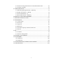
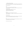
1. NAME OF EACH COMPONENT & ITS FUNCTION
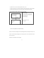
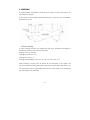
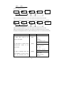
1.1 Name of Each Component
8
1
battery
2
rough collimator
3
LCD display
4
keyboard panel
5
keys
6
eyepieces: use for adjusting the definition of the crosshair.
7
protecting cover of eyepieces: by releasing this cover, you can implement the
mechanical adjustment of the reticle in order to correct the optical collimation line
error.
8
data transfer port: connecting with PDA or computer.
9
reflector of circular vial
10
circular vial
11 tribrach
12 lifting handle
13 model label
14 objective lens
15 focusing hand wheel: use for focusing of digital staff.
16
power/measure key: use for instrument power ON/OFF, and measure.
17 horizontal tangent hand wheel
18 horizontal dial: use for setting the horizontal direction value of the collimating
direction to 0 or other required values.
19
leveling screws of the tribrach
9
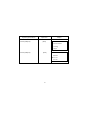
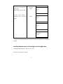
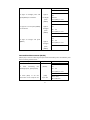
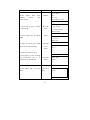
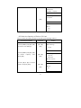
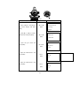
1.2 Operation Keys & Functions
key
name
function
Power
Power ON/OFF, and start to measure.
ON/OFF
Power ON: press once;
Measure
Power OFF: hold on for 2 seconds.
MENU
menu
Return to the menu list.
DIST
distance
In measurement status, press it to start measure
measure
the distance and display the distance.
↑↓
select
Turn the page of menu list or data list.
→
Number
Turn the left or right page when viewing the data,
←
moving
or move left or right in inputting status.
ENT
enter
To confirm the parameters or inputting data.
ESC
ESC
To escape from menu or any setting mode. Also
POW/MEAS
to go backspace to delete a character in
inputting mode.
0~9
number keys
Inputting numbers.
-
Mode
Use for inputting inverse staff. Set the inverse
.
of
setting
staff. You should activate this function in
inverse staff
parameter setting first.
illumination
Turn ON/OFF the illumination
decimal
Input a decimal point; while inputting symbols or
point
characters use this key to switch between
alphabets and numerals.
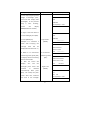
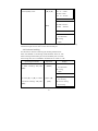
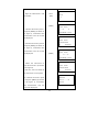
REC
Record key
To record the measured data
Enter the setting mode to set the measurement
SET
Set key
parameter, condition parameter and instrument
parameter.
SRCH
IN/SO
MANU
Search key
Use for searching and displaying the record data.
Intermediate
To measure the intermediate point or to skake
point/Stake
out
out key
measurement.
Manually
To input the data manually when the [MEAS] key
while
10
carrying
out
the
Leveling
REP
input key
cannot be used to take measurement.
Repeat
To repeat measuring the measured backsight or
measuring
foresight point in the leveling measurement
key
1.3 Display
The display adopts dot matrix LCD, displaying 4 lines, with 20 characters in each.
LCD illumination:
Press
ON/OFF.
to turn ON or OFF the illumination. It can be set in instrument parameters
too.
Setting Contrast
There’re 9 degrees for the contrast. Please refer to parameter setting to know how to
set the contrast.
Example:
Menu
1/2
►Standard Mode
Leveling
Adjust
Stardard Mode
Menu
1/2
Standard Mode
► Leveling
Adjust
Leveling Mode
11
Measure
Rod:
Dist:
N:3
>>>>>>>
Measuring
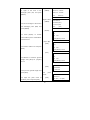
1.4 Symbols
key
function
key
function
Several pages or menus are
p
The current data has
been saved.
available which can be selected
a/b
by [▲] [▼],
b: total pages, a: current page
BM#
I
Battery level
Inst Ht
Instrument height
Bench Mark
CP#
Changeover Point
Staff Inversion
12
2. PREPARATION FOR MEASUREMENT
2.1 Mounting the Instrument
Placing the Tripod.
Type E aluminum tripod with flat or dome head tripod is required.
(1) Adjust the three legs of the tripod to a proper length and tighten the fixing screws
at the middle of the leg.
(2) Tighten the hexagonal nut on the head of the tripod in order to make the tripod
legs not too loosen. Place the tripod on a certain point, expand the legs until the
distance between each leg is about 1m. First, fix a leg, and move the other 2 legs to
make the head of the tripod approximately leveled. If necessary, adjust the length of
the tripod legs.
(3) Trample the legs into the earth or fix it well on the ground.
Mount the Instrument on the Head of the Tripod.
Take out the instrument carefully and place it on the head of the tripod.
(1) Aim the tripod central screw to the center of the tribrach and tighten the screw
until it is fixed at the head of the tripod.
(2) If you need to define an angle or a line through the horizontal dial, you should
center the instrument precisely with a plummet.
(3) Center the circular bubble by adjusting the three leveling screws of the tribrach. If
you are using a dome headed tripod, you should slightly loosen the tripod central
screw and rotate the instrument round the head of the tripod until the circular bubble
is centered, then tighten the screw.
Mounting the Instrument on a Certain Point (centering)
If you need to measure an angle or alignment, please precisely center the instrument
at a certain point with the plummet.
(1) Hang the plummet at the plummet hook of the central screw of the tripod.
(2) Adjust the plummet line to a proper height.
(3) In case the instrument is not centered at the known point, you can move the
instrument to that point without changing the position relationship between the
tripod leg and its head. First, put the tripod on the known point approximately until
13
the plummet is about 1cm away from the point. Second, grasp two legs of the tripod
and adjust the tripod by the third leg until the head of tripod is leveled approximately
with a proper height. Expand the legs of the tripod and fix it on the ground.
(4) Finally, observe the plummet and the hook and trample the legs into the ground.
(5) Slightly loosen the central screw of the tripod and move the instrument on the
head until the plummet is centered at the known point. Tighten the tripod central
screw.
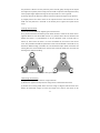
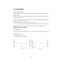
Leveling the Instrument
Center the circular bubble by adjusting the tribrach screw.
First, put the tribrach as the below picture shown. Rotate 2 screws at the same time in
opposite direction until the bubble moves to a position where the line between the
bubble and screw C is perpendicular to the line between screw A and B (refer to
Picture A). Then rotate the screw C to move the bubble to the center of the central
circle. This procedure should be repeated for times until the bubble is centered on any
directions. While leveling, remember the “Left Thumb Principle” which means that the
moving direction of the bubble is the same as that of the left thumb. Do not rotate the
leveling screw without thinking.
Notice: Do not touch the telescope during leveling.
Collimating and Focusing
(1) Sight at the digital staff with the rough collimator.
(2) Rotate the eyepiece slowly until the image of the crosshair becomes clear.
(3) Rotate the focusing hand wheel until the image of digital staff becomes clear.
Rotate the horizontal tangent to move the image of the staff to the center of the
14
vertical hair of the crosshair.
(4) Observe through the eyepiece. Move your eye slightly up, down, left and right to
check whether the relative position between the crosshair and the image of the staff is
not changed. If not, please return to step 1.
Notice: Measurement accuracy may be influenced if the crosshair and focusing is not
clear.
2.2 Power On
Press the power key (POW/MEAS).
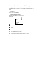
2.3 Remaining Battery Display
The battery symbol indicates the remaining battery.
battery symbol
Menu
►Standard Mode
Leveling
Adjust
Full
Sufficient
Half
Battery low. Please change the battery.
The power will be cut off soon. You need to change the battery.
15
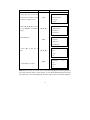
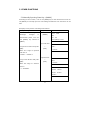
2.4 Setting the record mode
In order to save the measurement data in the internal memory of the instrument, the
data saving mode should be set as auto save before leveling measurement. The
default setting is “OFF”.
Flash:
Save the measured data (jobs) into the internal memory
•User can choose “Flash” in “Out Module” of “Condition” Setting if the data needs to
be saved in the flash.
•The maximum storage of memory is about 20,000.
•The maximum number of jobs is 500.
•Folder can not be created in the memory.
SD Card:
The measured data can be saved directly into the SD card.
• User can choose “SD” in “Out Module” of “Condition” Setting if the data needs to be
saved in the SD card.
Communication Port:
Connect DL-201 with external device by cable to receive the real-time measuring data.
User can only use Standard Measurement mode in this condition.
Off:
The measuring data will be displayed without storing and outputting, user can not use
Leveling Measurement mode in this condition.
See next page for the example.
16
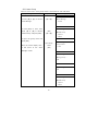
Operating Procedures
Operation
1. Press [Set] key to enter the
setting mode on Menu screen,
Display
Menu
[SET]
see detail in Chapter 9 “Set”.
1/2
►Standard Mode
Leveling
Adjust
2. Press [▲] or [▼] key to enter
the “Out Module” in Condition
Setting
[▲] or [▼]
setting.
Measurement
►Condition
Instrument
3.Press [ENT] key;
Condition
[ENT]
1/2
Point No.
Wait Time
►Out Module
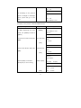
4. Press [▲] or [▼] key to
select.
Out Module
[▲] or [▼]
1/2
►OFF
Flash
SD
[ENT]
5.Press [ENT] to confirm.
Out Module
1/2
OFF
► Flash
SD
Note: When the output is in “Flash”, the “F” mark will be displayed on the top right side of
the screen; when the output is in SD card, the “S” mark will be displayed; when the output
is by USB, the “U” mark will be displayed; when the output is off, no mark will be displayed.
17
2.5 SD Card
User can use SD card for data storage, data copy and data search.
SD card function only can be used while the”Out Module” is set as “SD”
To format the SD card please refer to the Chapter 7 “Format Flash or SD Card”
For SD card management, please refer to the Chapter 8 “Data Manage”
Note: When the system is loading data from the SD card, do not remove the battery
and SD card, otherwise, the saved data will be damaged, even it will influence on the
memory storage; the defective SD card may damage the memory storage.
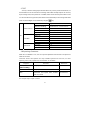
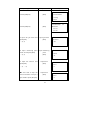
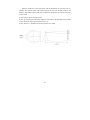
2.6 Menu
The menu includes following programs, the functions located in different menus which can’t
be always optional at the same time. (You may change the mode for different funcitons)
For example, when the “Out Module” is “Communication port” or “OFF”, the Leveling Mode
and Adjust Mode can not be carried out. If user enters the Leveling mode, the “Start Leveling”
and “Continue Leveling” can not be chosen at the same time.
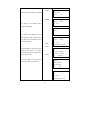
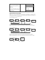
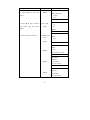
1st Menu
Standart
Mode
Leveling
Menu
Adjust
2nd Menu
Measure
S.O G.H
S.O H.D
S.O Dist
Start Leveling
Continue
End Leveling
3rd Menu
4th Menu
BFFB
BBFF
BF/BIF
Outward/Return
Method A
Method B
Make Group
Input Pt
Data
manage
Flash/SD
Flash/SD
Flash/SD
Flash/SD
Flash/SD
Flash/SD
Search
Copy Job
Delete Job
Check Capacity
File Out
Format
18
Job/PN/BM#
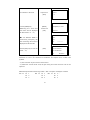
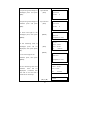
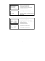
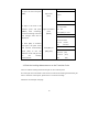
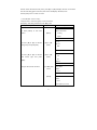
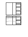
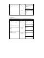
2.7 SET
“Set” key is used for setting the parameters. When carry out the precise measurement, it is
recommended to use the continuous measuring mode which will help improve the accuracy
by the average value; “Auto power off” is available, which means that the power will be cut off
in 5 minutes without any operation; Data will be saved automatically in the Leveing mode while
power off; The backlight can be switched by using the
Measurement
SET
Condition
Instrument
key.
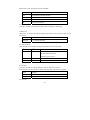
Measure Mode
Single/N Times/Continuous
Minimum Reading
Srandard 1mm/Precise 0.1mm
Inverse Mode
Use / No Use
Unit
Diff
m(meter) / ft(US.ft)
B-F Dif/TolDil/StafDif
Point No.
Wait Time
Out Module
Communication
Auto Off
Contrast
Backlight
Instrument Info
Increase/Descend
1~9 Second
OFF/Flash/SD/Communication
Standard/User
5 min / Off
1~9
On/Off
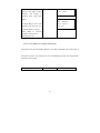
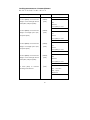
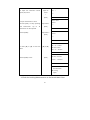
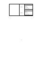
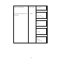
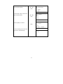
2.8 Inputting Characters
When the “Out Module” is on, user can input the alphabets and numerals in the place that
needs to be noted.
Lowercase letters and symbols are only available inputted into the Info, on other
inputting status, only capital letter and number are available.
Program
Group
Character
Maximum
Only capital letter, number and “-” etc.
8 Characters
Job
Only capital letter number and “-” etc.
8 Characters
Info
Lowercase and capital letter, number
16 Characters
(SD Card Only)
and all symbols
For example: Input “Tp#7” in Info1
19
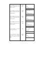
Operating Procedures
Operation
Display
Measure
1. Press [●] key to enter the
[●]
capital letter inputting mode.
=>
2. Press [◄] or [►] key until the
cursor
flashes
in
the
Info#1
[◄]or[►]
let
Measure
Info#1 ?
er “T”.
=>
QRSTUVWXYZABCDEFGHIJ
3. Press [ENT] key to enter “T”
which will be displayed at the
Measure
[ENT]
bottom of the line.
Info#1 ?
=>
JKLMNOPQRSTUVWXYZABC
Measure
4. Press [●] to input the lowercase
[●]
lette.
Info#1 ?
=> T
qrstuvwxyzabcdefghij
Measure
5. Press [◄] or [►] key until the
cursor flashes in the letter “p” and
press[ENT].
[◄]or[►]
[ENT]
Info#1 ?
=> T
ghijklmnopqrstuvwxy
Measure
Info#1 ?
=> Tp
fghijklmnopqrstuvwxy
20
Measure
[●]
6. Press [●] to enter the symbol
inputting mode.
Info#1?
=> Tp
?@[_]^{|}!”#$%&’()*
Measure
7. Press [◄] or [►] key until the
[◄] or [►]
cursor flashes in the letter “#”,
[ENT]
then press [ENT].
Info#1?
=> Tp
[_]^{|}!”#$%&’()*+-
Measure
8. Press [ESC] key to enter
[ESC]
numeral inputting mode.
Info#1?
=> Tp#
[_]^{|}!”#$%&’()*+-
Measure
9. Press numeric key [7], after
[7]
confirming the inputted content,
[ENT]
Info#1?
=> Tp#7
press [ENT] key.
●
Use [●] key to switch the input mode.
Capital letter
ABCD
Lowercase letter
abcd
Symbol
!”#$
●Available symbols to input are as follow:
!″ #$%& ()*+-./ :;<=>?@[_]^\ {|}
2.9 Staff Collimation and Focus
(1) Focusing
Adjust the eyepiece focusing screw until the crosshair can be seen clearly. Then adjust
the focusing screw until you can see the staff clearly through the objective lens.
A precise focusing can shorten the measuring time and improve the accuracy.
21
Measurement of high accuracy requests precise focusing as well as continuous
measures.
(2) Obstacles
Measurement can be implemented if the staff is blocked less than 30%. Even if the
crosshair center is blocked, as long as the field of view is blocked less than 30%,
measurement still can be implemented. However, in this case, the accuracy might be
affected.
(3) Shadow
The surveying accuracy may be influenced if the staff is covered by shadow. In some
cases, it is not possible to measure.
(4) Backlight
If the background of the staff is very bright, it will affect the contrast of the staff, the
digital level might not be able to measure. You can cover something ahead of the
objective len in order to reduce the background light invading to the len. When a
strong light comes into the eyepiece, it might not be able to measure either. You can
also cover the eyepiece in order to block the strong light from coming into the
eyepiece.
When the sun is in a low position (for example, in the morning or at night fall), or if the
sun light comes into the objective lens directly, it is suggested to block the sunlight
with hands.
2.10 Surveying Note
In order to make full use of the functions of instrument, please pay attention to the
following:
(1) Set up the staff in bright place. If possible, prolong the staff completely. If
illumination is employed, it is suggested to illuminate the whole staff, otherwise the
accuracy might be affected.
(2) The shortest distance between instrument and staff is 1.5m.
(3) It will affect the accuracy when staff blocked. If the bar code on the staff is
22
blocked by tree branches or leaves, the digital level might display error, or the
accuracy decreased.
(4) If the place where the staff located darker than that of the eyepiece, an error
might occur; you can block the light for the eyepiece with something proper.
(5) Deflection and pitching of the staff may affect the accuracy. During the
measurement, make sure the staff is paralleled to the vertical hair of the reticle. The
staff should be unfolded completely and fixed well. Make sure the joints of the staff
are well and precise. Avoid to measure through the glass window.
(6) After a long storage or transportation, check and calibrate the digital and
optical sight errors. Then adjust the circular vial and keep the optical parts clean.
3. STANDARD MODE
Standard Mode includes Measure, S.O G.H, S.O H.D and S.O Dist.
3.1 Measure
In Measure function, user can measureing the staff reading and distance without
calculating the ground height. When the “Out Module” in “Condition Setting” is set as
“Flash” or “SD”, user needs to input job name and information. All Data will be saved in
the flash or SD card.
For the measuring time, please refer to the “Measure Mode” of “Measurement
Set”
[Example]: “Out Module” is “Flash”, “Measure Mode” is 3 times
23
Operating Procedures
Operation
Display
Menu
1. Press [ENT] key.
[ENT]
1/2
►Standard Mode
Leveling
Adjust
Standard Mode
2. Press [ENT] key.
[ENT]
►Measure
S.O G.H
S.O H.D
3. Input the job name and
press [ENT].
Input job name
[ENT]
※1), 3)
4. Input measuring point
name 12 and press [ENT].
※1), 3)
5. Input the note1-3 and
press [ENT].
Measure
Job Name?
=>J01
Input measuring
point
[ENT]
Input Info 1
[ENT]
※1) ※3)
Measure
Meas#
=>12
Measure
Info#1?
=>1
● If user want to skip the
Input Info 2
note 2 and enter to step 6, it
[ENT]
just needs to press [ENT] key.
Measure
Info#2?
=>1
24
1/2
Measure
Input Info 3
6. Collimate at the staff.
[ENT]
Info#3?
=>1
Measure
[MEAS]
7. Press [MEAS] key.
Press[MEAS] to meas
Measuring for 3 times and
Continuous
the result will be displayed
[ESC]
Meas#:12
for M seconds※4)※5).
Measure
● If the Measure Mode is
Rod:
Continuous, press [ESC], the
Dist:
last measuring result will be
N:3
>>>>>>>
displayed for M seconds.
Measure
8. Press [REC] key to save the
[REC]
1/2
Rod Ave:0.8263m
result. ※6).
Dist Ave:18.818m
N:3
δ:0.04mm
※1) The maximum of job name is 8 characters of capital letter or number, and the
maximum of note is 16 characters of lowercase and capital letter, number and
symbols.
※2) The maximum of point name is 8 characters.
※3) When the “record mode” is off, the job name, point name and note can not be
inputted.
●Relationship between measuring number(Mn)and point name(Pn)is as follow:
Mn 11
Pn
1
Pn
Pn
Mn 12
Pn
1
2
Pn
3
Pn
Pn
1……
2
Pn
2
3
Pn
3
25
Mn 13
·
·
·
·
·
·
·
·
·
※4) “Wait Time” can be set manually, please refer to “Set”
※5) After measuring, the result will be displayed. Press [▲] or [▼] to switch the page.
※6) After being saved, the point name will increase or descend automatically.
After measuring, press [▲] or [▼] key to switch the pages
Distance display:
Measure
N-times: average surveying value
1/2
Rod Ave:0.8263m
Continuous: last surveying value
Dist Ave:18.818m
N: Surveying time
N:3
δ: Standard offset
Measure
δ:0.04mm
measured point name
2/2
point name
Meas#:12
PN:1
3.2 S.O G.H (Stake out Ground Point)
System can measure the height of corresponding point B by the height value (Ha+ H),
which is calculated by the height (Ha) of the known point A. The measurement result
will not be saved.
Please see the example in the next page.
26
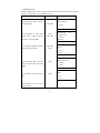
Operating Procedures
1. Press [ENT] key.
Operation
[ENT]
Display
Menu
1/2
►Standard Mode
Leveling
Adjust
2. Press [ENT] key.
[ENT]
Standard Mode
Measure
►S.O G.H
S.O H.D
27
1/2
3. Input the ground height of
Input BS G.H
backsight point and press
[ENT]
[ENT].
S.O G.H
Input BS G.H
=23.000
4. Input the ground height of
Input SO G.H
stakeout point and press
[ENT]
[ENT].
m
S.O G.H
Input SO G.H
=25.000
5. Focus and sight at the
backsight point, then press
m
S.O G.H
[MEAS]
[MEAS].
Meas BS Pt
Press[MEAS] to meas
S.O G.H
6. The measuring result of
backsight
point
will
be
[ENT]
displayed, then press [ENT]
F
B Rod:
1.512m
B Dist:
26.78m
N:3
δ:0.4mm
key.
[MEAS]
7. Focus and sight at the
Meas SO Pt
stakeout point, then press
[MEAS].
Press[MEAS] to meas
S.O G.H
8. The measuring value and
stakeout
S.O G.H
value
will
S Rod:
be
1.612m
S.O:↑2.100m
displayed. ↑ indicates that
N:3
the staff is too low and it
needs to be moved up.
[▲] or [▼]
28
S.O G.H
δ:0.4mm
9. Press [▲] or [▼] key to
[ENT]
S Dist:
switch to the page of sight
distance
and
height
G.H:
26.78m
22.90m
of
stakeout point, then press
[ENT].
S.O G.H
REP:
New Meas
10. Press [REP] to start a new
ENT: Continue
stakeout job and start over
ESC:
Exit
backsight point surveying.
Press
[ENT]
to
continue
stakeout measurement.
Press [ESC] to exit.
3.3 S.O H.D (Stake out Height Difference)
According to the inputted height difference
H which calculated from known point A
and point B, system can measure out the corresponding point B, the measurement
result will not be saved.
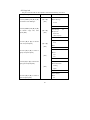
Operating Procedures
Operation
29
Display
[ENT]
1. Press [ENT] key.
Menu
1/2
►Standard Mode
Leveling
Adjust
[ENT]
2. Press [ENT] key.
Standard Mode
1/2
Measure
S.O G.H
►S.O H.D
3. Input height difference
Input H.D
[ENT]
value and press [ENT].
S.O H.D
Input SO H.D
=-1.000
4. Focus and sight at the
[MEAS]
backsight point, then press
m
S.O H.D
Meas BS Pt
[MEAS].
Press[MEAS] to meas
5. The measuring result of
backsight
point
will
[ENT]
be
displayed, then press [ENT]
key.
S.O H.D
1.512m
B Dist :
26.78m
N:3
[MEAS]
6. Focus and sight at the
F
B Rod:
δ:0.4mm
S.O H.D
Meas SO Pt
stakeout point, then press
Press[MEAS] to meas
[MEAS].
[▲] or [▼]
30
S.O H.D
7. The measuring value and
stakeout
value
will
[ENT]
be
S Rod:
1.612m
H.D:↓0.900m
displayed. ↓ indicates that
N:3
δ:0.4mm
the staff is too high and it
needs to be moved down.
S.O H.D
8. Press [▲] or [▼] key to
S Dist:
switch to the page of S Dist
H.D:
26.78m
-0.100m
(Sight Distance) and H.D
(Height
Difference)
of
stakeout point, then press
S.O H.D
[ENT].
REP:
New Meas
ENT: Continue
9. Press [REP] to start a new
ESC:
Exit
stakeout job and start over
backsight point surveying.
Press
[ENT]
to
continue
stakeout measurement.
Press [ESC] to exit.
3.4 S.O Dist(Stake out Distance)
According to the inputted distance Dab from known point A to point B, system can
measure the corresponding point B. The measurement result will not be saved.
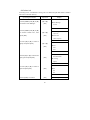
Operating Procedures
Operation
31
Display
1. Press [ENT] key.
[ENT]
Menu
1/2
►Standard Mode
Leveling
Adjust
2. Press [▼] key.
[▼]
Standard Mode
1/2
Measure
S.O G.H
►S.O H.D
3. Press [ENT] key;
[ENT]
Standard Mode
2/2
►S.O Dist
4. Input stakeout distance
and press [ENT];
Input S.O Dist
[ENT]
S.O Dist
Input SO Dist
=15.000
5. Focus and sight at the
[MEAS]
stakeout point, then press
m
S.O Dist
Meas SO Pt
[MEAS].
Press[MEAS] to meas
6. Press [▲] or [▼] to switch
[▲] or [▼]
page and display the rod
[ENT]
reading and input value, then
S Dist:
Dist:
press [ENT].
7. Press [ENT] to continue
S.O Dist
[ENT] or [ESC]
stakeout measurement.
32
←11.78m
S.O Dist
S Rod:
Press [ESC] to exit.
26.78m
1.005m
Input:
15.00m
S.O Dist
ENT:Continue
ESC:Exit
33
4. LEVELING
In Leveling Mode, “Out Module” should be set as “Flash” or “SD”. In this section, we
take “Flash” for example.
If user wants to save leveling measured data directly to SD card, the “Out Module”
should be set as “SD”.
4.1 Start Leveling
In “Start Leveling” function, user should input job name, pointname and height of
benchmark, and then start to do the measuring.
Leveling 1: B1→F1→F2→B2
Leveling 2: B1→B2→F1→F2
Leveling 3: B→F/ B→I→F
Leveling 4:Outward/Return:B1→F1→F 2→B 2/ F 1→B 1→B 2→F 2
After measuring a station, user can switch off the instrument to save power, the
instrument will automatically continue the next station measurement after power on. If
the measurement do not finish while power off, the point needs to be remeasured
after switching on the instrument.
34
Operating Procedures
Operation
[ENT]
1. Press [ENT] key.
Display
Menu
1/2
Standard Mode
► Leveling
Adjust
[ENT]
2. Press [ENT] key.
Leveling
►Start Leveling
Continue Leveling
End Leveling
3. Input job name and press
Input Job Name
[ENT]
[ENT].
Leveling
Job Name?
=>J01
4. Press [▲] or [▼] to choose
[ENT]
Leveling
►B1→F1→F2→B2
Leveling Measurement mode
B1→B2→F1→F2
and press [ENT];
B→F/B→I→F
5. Press [▲] or [▼] to choose
from
Input
BS
Pt
or
Transfer(call up an existed
[▲] or [▼]
[ENT]
Leveling
1/2
F
Input BS Pt
Transfer
basepoint height). ※1) Then
press Enter.
6. Input the point name of
benchmark and press [Ent]
Input BM#
[ENT]
Leveling
BM#?
=>B01
35
F
7. Input the information and
press [ENT].
Input Info
[ENT]
(Press [ENT] directly to skip).
F
Info#1
=>1
8. Input ground height of
backsight point and press
[ENT]
[ENT].
F
Info:#2
=>1
F
Info:#3?
=>1
F
Input BS G.H
=100 m
※1) The existed point data can be input in the menu→Data Manage→Input Pt.
※2) User can input three groups of notes, each notes has 16 characters of numbers or
symbols
Leveling: Measurement of backsight and foresight data
Leveling measurement 1: B1→F1→F2→B2
Please see the example next page.
36
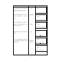
Operating Procedures
Operation
Display
1. After inputting the ground
height of backsight point,
Level BFFB
the screen will
Bk1
display “Bk1
(backsight). If the previous
BM#:B01
step
Press [MEAS] to meas
is
screen
“Start
Leveling”,
will
display
BM#(Benchmark number).
2. Sight at the staff which is
Level BFFB
on the backsight point (Bk1).
Bk1
Sight at Bk 1
3. Press [MEAS] key.
Example: If it measures 3
value
will
B1Rod:0.8259m
B1Dist: 3.914m
4. When it is in continuous
In continuous
measuring mode, press [ESC]
measuring mode
to display the last measuring
[ESC]
data for M seconds.
Then
display
the
screen
will
“Fr1”
and
the
foresight point name will
increase
or
automatically.
descend
Now
>>>>>>>>>
Level BFFB
be
displayed for M seconds※1).
5.
BM#:B01
[MEAS]
times, after surveying, the
average
F
N:3
>>>>>>>>>
Level BFFB
1/2
B1Rod Ave:0.8259m
B1Dist Ave: 3.914m
N:3
δ:0.00mm
Sight at Fr1
[MEAS]
Level BFFB
press
[ESC] can modify the point
Fr1
name. After that, collimate
PN
the staff in the foresight
Press [MEAS] to meas
37
:P01
point (Fr1).
Level BFFB
1/2
F1Rod Ave:0.8260m
F1 Dist Ave: 3.914m
6. Press [MEAS].
After
average
N:3
measuring,
value
δ:0.02mm
the
will
be
Level BFFB
displayed for M seconds.
Fr2
PN
7. Sight at the staff in the
Sight at Fr2
foresight point (Fr2) and
[MEAS]
press [MEAS].
:P01
Press [MEAS] to meas
Level BFFB
1/2
F2 Rod Ave:0.8260m
8.
After
average
measuring,
value
F2 Dist Ave: 3.913m
the
will
N:3
be
δ:0.02mm
displayed for M seconds.
Level BFFB
Bk2
BM#:B01
9. Focus and sight at the staff
Sight at Bk 2
in the backsight point (Bk2)
[MEAS]
Press [MEAS] to meas
Level BFFB
and press [MEAS].
1/2
B2 Rod Ave:0.8261m
B2 Dist Ave: 3.915m
10.
If
backsight
there
and
are
N:3
more
foresight
points, user can start from
the step 2 to 9.
※1) User can set the display time in the “Condition Setting”.
After measuring, following data will be displayed.
Press [▲] or [▼] key to turn page.※
38
δ:0.02mm
After measuring the backsight point 1(Bk 1), press [▲] or [▼] to display the following
interface:
The following items are only displayed on
Level
BFFB
1/2
the N-times measuring mode:
B1 Rod Ave:0.8259m
Distance to the Backsight point
B1 Dist Ave : 3.914m
N times mode: Average value
N:3
Continuous mode: Last measuring value
δ:0.00mm
N: Total measuring times
δ: Standard offset
Level
BFFB
2/2
Backsight point name
BM#:B01
After measuring the foresight point 1(Fr 1), press [▲] or [▼] to display the following
interface:
1/2
Disance to the foresight point
F1 Rod Ave:0.8260m
N times mode: Average value
F1 Dist Ave : 3.914m
Continuous mode: Last measuring value
N:3
N: Total measuring times
Level
BFFB
δ:0.02mm
δ: Standard offset
Level
BFFB
2/2
H.D 1: -0.0001m
Height Difference from Bk1 to Fr1
Fr GH1:99.9999m
Ground height of forsight point
PN
:P01
After measuring the foresight point 2(Fr 2), press [▲] or [▼]to display the following
39
interface:
Disance to the foresight point
Level
BFFB
1/2
N times mode: Average value
F2 Rod Ave:0.8260m
Continuous mode: Last measuring value
F2 Dist Ave : 3.913m
N: Total measuring times
N:3
δ: Standard offset
δ:0.02mm
Level
BFFB
2/2
d :0.000m
d:backsight distance sum-foresight distance sum
Σ:7.828m
Σ:backsight distance sum+oresight distance sum
PN
Foresight point name
:P01
After measuring the backsight point 2(Bk 2), press [▲] or [▼]to display the following
interface:
Distance to the Backsight point
Level
BFFB
1/3
N times mode: Average value
B2 Rod Ave:0.8260m
Continuous mode: Last measuring value
B2 Dist Ave :3.915m
δ: Standard offset
N:3
δ:0.02mm
E.V:Elevation offset difference=(Bk1-Fr1)-(Bk2-Fr2)
Level
BFFB
E.V Limit:
d:
Σ:
2/3
0.0mm
d: backsight distance sum-foresight distance sum
Σ:backsight distance sum+foresight distance sum
0.001m
Height Difference from Bk2 to Fr2
7.828m
Ground height of foresight point
Level
BFFB
3/3
Backsight point name
H.D 2:0.0000mm
Fr GH2: 100.0000m
BM#:B01
40
Leveling measurement 2: B1→B2→F1→F2
Operating Procedures
Operation
Display
1. After inputting the ground
Level
height of backsight point, the
Bk1
screen
BM#:B01
will
display
“Bk1
(backsight).If the previous step is
“Start
Leveling”,
screen
BBFF
Press [MEAS] to meas
will
display BM (Bench Mark).
2. Sight at the staff in the
Sight at Bk 1
backsight point (Bk1) and Press
[MEAS]
[MEAS] key.
BBFF
Bk1
BM#:B01
>>>>>>>>>>>
3. Focus and sight at the staff in
Sight at Bk 2
the backsight point (Bk2) and
[MEAS]
press [MEAS].
Level
BBFF
Bk2
BM#:B01
Press [MEAS] to meas
4. Sight at the staff in the
Sight at Fr1
foresight point [Fr1].
Meanwhile
Level
press
[ESC]
can
[MEAS]
change the foresight point name.
Level
BBFF
Fr1
PN:P01
Press [MEAS] to meas
Press [MEAS] to measure.
5. Sight at the staff in the
foresight point (Fr2) and press
[MEAS].
Sight at Fr2
[MEAS]
Level
BBFF
Fr2
PN:P01
Press [MEAS] to meas
6. Move the station and sight at
41
the staff in the backsight point
Sight at Bk 1
(Bk1), and then press [MEAS].
If there are more backsight and
[MEAS]
Level
BBFF
Bk1
foresight points, please repeat
PN:P01
step 2 to 5.
Press [MEAS] to meas
After measuring, the following data will be displayed.
Press [▲] or [▼] key to turn page※
After measuring the backsight point 1(Bk 1), press [▲] or [▼] to display the
following interface:
Level
BBFF 1/2
The following items are only displayed on the
B1 Rod Ave:0.8259m
N-times measuring mode:
B1 Dist Ave : 3.914m
Distance to the Backsight point
N:3
N times mode: Average value
δ:0.00mm
Continuous mode: Last measuring value
Level
BM#:B01
BFFB
2/2
N: Total measuring times
δ: Standard offset
Backsight point name
After measuring the backsight point 2(Bk 2), press [▲] or [▼]to display the following
interface:
42
Level
BBFF
1/2
Distance to the Backsight point
B2 Rod Ave:0.8260m
N times mode: Average value
B2 Dist Ave:3.915m
Continuous mode: Last measuring value
N:3
δ: Standard offset
Level
δ:0.02mm
BBFF
2/2
Backsight point name
BM#:B01
After measuring the foresight point 1(Fr 1), press [▲] or [▼] to display the following
interface:
Disance to the foresight point
Level
BBFF
1/2
N times mode: Average value
F1 Rod Ave:0.8260m
Continuous mode: Last measuring value
F1 Dist Ave: 3.914m
N: Total measuring times
N:3
δ: Standard offset
Level
δ:0.02mm
BBFF
2/2
H.D 1: -0.0001m
Height difference from Bk1 to Fr1
Fr GH1:99.9999m
Ground height of foresight point
PN
:P01
After measuring the foresight point 2(Fr 2), press [▲] or [▼] to display the following
interface:
43
Disance to the foresight point
Level
BBFF
1/3
N times mode: Average value
F2 Rod Ave:0.8260m
Continuous mode: Last measuring value
F2 Dist Ave: 3.913m
N: Total measuring times
N:3
δ: Standard offset
δ:0.02mm
Level
BBFF
2/3
E.V:Elevation offset difference=(Bk1-Fr1)-(Bk2-Fr2)
E.V Limit:0.0mm
d: backsight distance sum-foresight distance sum
d :0.000m
Σ:backsight distance sum+oresight distance sum
Σ:7.828m
Foresight point name
Height Difference from Bk2 to Fr2
Level
BBFF
3/3
Ground height of foresight point
H.D 2: 0.0000m
Fr GH2:100.000m
PN
:P01
Leveling measurement 3: B→F/B→I→F
Operating Procedures
Operation
Display
Level
BIF
1. After inputting the ground
Bk1
height of backsight point, the
BM#:B01
screen
Press [MEAS] to meas
will
display
“Bk1
(backsight).
Sight at Bk 1
2. Sight at the staff in the
[MEAS]
backsight point (Bk1) and Press
Level
BIF
Bk1
BM#:B01
>>>>>>>>>>>
[MEAS] key.
44
3. Press [IN/SO] ( Intermediate
[IN/SO]
and Stake out).
Level
BIF
BRod Ave:0.8260m
BDist Ave: 3.913m
N:3
4. Chosse “Intermediate” and
[▲] or [▼]
[ENT]
press [ENT].
δ:0.02mm
Level
BIF
Fr1
Pn :P01
Press [MEAS] to meas
5. Input the point name of
Point name
intermediate point and press
[ENT]
Level
BIF
►InterMediate
[ENT].
Stake Out
Info
6. Input the information and
[ENT]
press [ENT].
InterMediate
PN
?
=>TP01_
[MEAS]
InterMediate
7. Focus and collimate the staff in
Info#1?
the intermediate point.
=>
Press [MEAS] to measure.
8.
Press [REC] to save data;
[REC]
InterMediate
[ESC]
PN
:TP01
press [ENT] if user wants to
continue
intermediate
point
Press [MEAS] to meas
measurement; press [ESC] to exit.
45
Sight at Fr1
9. Sight at the staff in the
[MEAS]
InterMediate
Rod Ave:0.9030m
foresight point (Fr1) and press
Dist Ave:17.008m
[MEAS].
N:3
Sight at Bk 2
[MEAS]
10. Focus and sight at the staff in
SaveData [REC]
Exit
press [MEAS].
[IN/SO]
[ESC]
Level
BIF
Fr1
11. Press [IN/SO] to choose
PN
“Intermediate point and Stakeout
:P01
Press [MEAS] to meas
measurement”
[▲] or [▼]
[ENT]
12. Choose “Stake Out” and press
Level BIF
Bk2
PN
[ENT].
:P01
Press [MEAS] to meas
[ESC]
Level
BIF
Fr2
13. Whether to load the ground
PN
height data, [ENT] for yes,[ESC]
:P02
Press [MEAS] to meas
for no.
[ENT]
Level
BIF
InterMediate
► Stake Out
14. Input the ground height and
S.O
point
name
15. Input the point name of
InterMediate
Continue [ENT]
the backsight point (Bk2) and
press [ENT].
δ:0.02mm
[ENT]
stakeout point and press [ENT].
46
Stake Out
Load Data?
Yes: [ENT]
No: [ESC]
Input note
[ENT]
16. Input the Info and press [ENT]
Stake Out
Input SO G.H
=3.000
[MEAS]
m
Stake Out
Set G.H:
17. Sight at the stakeout point
PN
3.000m
:G01
and press [MEAS].
Stake Out
Info#1
=>_
18. Screen will display the S.O
Rod (Stakeout rod value) and S.O
Stake Out
H.D (Direction and Height of the
Set G.H:
staff movement).
PN
[REC]
3.000m
:G01
Press [MEAS] to meas
[ESC]
19. Press [REC] to save data; press
Stake Out
[ENT] if user wants to continue
S.O Rod:
intermediate point measurement;
press [ESC] to exit.
[ENT]
20. Press [ENT] to continue the
0.9980m
S.O H.D: ↓0.0275m
N:3
δ:0.02mm
Stake Out
foresight point measurement.
SaveData [REC]
Continue [ENT]
Exit
[ESC]
Level
BIF
Fr1
PN
:P02
Press [MEAS] to meas
47
After measuring the backsight point 1(Bk 1), press [▲] or [▼] to display the following
interface:
Level
BIF
1/2
Distance to the Backsight point
BRod Ave:0.8260m
N times mode: Average value
BDist Ave:3.915m
Continuous mode: Last measuring value
N:3
δ:0.02mm
δ: Standard measurement
Level
BIF
2/2
Backsight point name
PN:P05
After measuring the foresight point 1(Fr 1), press [▲] or [▼] to display the following
interface:
Level
BIF
1/3
Disance to the foresight point
F2Rod Ave:0.8260m
N times mode: Average value
F2Dist Ave: 3.913m
Continuous mode: Last measuring value
N:3
N: Total measuring times
δ:0.02mm
δ: Standard offset
Level
BIF
2/3
Fr GH:100.000m
Ground height of the foresight point
d :0.000m
d: backsight distance sum-foresight distance sum
Σ:7.828m
Σ:backsight distance sum+oresight distance sum
Level
BIF
H.D 2: 0.0000m
PN
3/3
Height Difference from Bk2 to Fr2
Foresight point name
:P01
After measuring the intermediate point, press [▲] or [▼] to display the following
interface:
48
InterMediate
1/2
Distance to intermediate point
Rod Ave:0.8260m
N times mode: Average value
Dist Ave:3.915m
Continuous mode: Last measuring value
N:3
δ: Standard measurement
δ:0.02mm
InterMediate
2/2
Ground height of intermediate point
Int GH:2.008m
Point name of intermediate point (the point
PN
name will increase or descend only after
:TP05
being saved.)
After staking out, press [▲] or [▼] to display the following interface:
Measured value of the staff
Stake Out
S.O Rod:
S.OH.D:
N:3
1/2
0.8260m
↑ 3.915m
δ:0.02mm
N times mode: Average value
Continuous mode: Last measuring value
Height
difference
of
staff
downward movement.
δ:Standard measurement
Stake Out
Dist:
2/2
12.008m
S.O G.H0:2.005m
Sight distance of stakeout point
Ground height of stakeout point
49
upward
or
Leveling measurement 4: Outward/Return
B1→F1→F 2→B 2/ F 1→B 1→B 2→F 2
Operating Procedures
Operation
1. Press [MEAS] to measure the
[MEAS]
height of the backsight bench
[ENT]
mark (Bk1) and press [ENT].
Display
Outward
BFFB
1
Bk1
BM#:B01
Press [MEAS] to meas
2. Press [MEAS] to measure the
[MEAS]
height of foresight point (Fr1)
[ENT]
and press [ENT].
Outward
BFFB
1
Fr1
PN:P01
Press [MEAS] to meas
3. Press [MEAS] to measure the
[MEAS]
height of foresight point (Fr2)
[ENT]
and press [ENT].
Outward
BFFB
1
Fr2
PN:P01
Press [MEAS] to meas
4. Press [MEAS] to measure the
[MEAS]
height of the backsight bench
[ENT]
Outward
BFFB
1
Bk2
BM#:B01
mark (Bk2) and press [ENT].
Press [MEAS] to meas
5. Press [ENT] to continue
[ENT]
Leveling measurement.
Outward
ENT:
Next Meas
REP:
Repeat
MENU:End
50
BFFB
1
Outward
6. Press [MEAS] to measure the
[MEAS]
height of foresight point (Fr1)
[ENT]
and press [ENT].
FBBF
2
Fr1
PN:P02
Press [MEAS] to meas
7. Press [MEAS] to measure the
[MEAS]
height of backsight point (Bk1)
[ENT]
and press [ENT].
Outward
FBBF
2
Bk1
PN:P01
Press [MEAS] to meas
8. Press [MEAS] to measure the
[MEAS]
height of backsight point (Bk2)
[ENT]
and press [ENT].
Outward
FBBF
2
Bk2
PN:P01
Press [MEAS] to meas
9. Press [MEAS] to measure the
[MEAS]
height of foresight point (Fr2)
[ENT]
Outward
FBBF
2
Fr2
PN:P02
and press [ENT].
Press [MEAS] to meas
Outward
10. Press [ENT] to continue
[ENT]
Leveling measurement.
BFFB
ENT:
Next Meas
REP:
Repeat
2
MENU:End
Outward
11. Press [MEAS] to measure
[MEAS]
the height of the backsight
[ENT]
bench mark (Bk1) and press
BFFB
3
Bk1
PN:P02
Press [MEAS] to meas
[ENT].
51
Outward
12. Press [MENU] to end the
[MENU]
Leveling measurement.
FBBF
ENT:
Next Meas
REP:
Repeat
6
MENU:End
13. Press [ENT] to confirm
Outward
[ENT]
FBBF
6
Even station,
End meas?
Yes: [ENT]
Outward
14. Press [▲] [▼] to choose
[▲][▼]
“End Outward”.
[ENT]
press [ENT] to confirm.
Input PN
[ENT]
FBBF
6
CP Close
►End Outward
Outward
15. Input PN (point name) and
No: [ESC]
PN
FBBF
6
FBBF
6
?
=>_
Outward
Info#1
16. Input the information and
press [ENT] to confirm.
Input Info
=>_
[ENT]
Outward
h
17. Press [▲] [▼] to view the
FBBF 6
CP 0.558m
[▲][▼]
measurement data.
hΣCP 1.007m
18. Press [ENT] to continue the
[ENT]
return measurement.
ΣD
52
CP 52.00m
1/2
Outward
FBBF 6
2/2
19. Press [MEAS] to measure
[MEAS]
ΣD
BM 108.05m
the height of backsight point
[ENT]
G.H
BM 5.007m
(Bk1) and press [ENT].
[MEAS]
20. Press [MEAS] to measure
[ENT]
the height of foresight point
Return
BFFB
1
Bk1
BM#:P06
(Fr2) and press [ENT].
Press [MEAS] to meas
[MENU]
Return FBBF
2
Fr2
21. Press [MENU] to end the
PN
measurement.
:P07
Press [MEAS] to meas
[ENT]
22. Press [ENT] to confirm.
Return FBBF
6
ENT:
Next Meas
REP:
Repeat
MENU:End
[▲][▼]
Return FBBF
6
Even station,
23. Press [▲][▼] to choose.
Point name
End meas
[ENT]
Yes: [ENT]
No: [ESC]
24. Input the point name and
press [ENT] to confirm.
Return FBBF
6
CP Close
Info
►End Return
[ENT]
25. Input the note and press
Return FBBF
[ENT] to confirm.
PN ?
53
6
=>
[▲][▼]
26. Press [▲][▼] to view the
measurement data.
Return FBBF
Info#1
6
=>
[ENT]
27. Press [ENT] to exit Return
Leveling measurement.
Return FBBF 6
h
1/2
CP 0.558m
hΣCP 0.003m
ΣD
CP 52.00m
Return FBBF 6
ΣD
BM 110.08m
G.H
BM 5.003m
Menu
2/2
1/2
Standard Mode
► Leveling
Adjust
After measuring, following data will be displayed.
Press [▲] or [▼] key to switch the page
After measuring the backsight point 1(Bk 1), press [▲] or [▼] to display the following
interface:
The following items only display on the
Level BFFB
1/2
N-times measuring mode:
Distance to the Backsight point
54
B1Rod Ave:0.8259m
N times mode: Average value
B1Dist Ave: 3.914m
Continuous mode: Last measuring value
N:3
N: Total measuring times
δ:0.00mm
δ: Standard offset
Level BFFB
2/2
Backsight point name
BM#:B01
After measuring the foresight point 1(Fr 1), press [▲] or [▼] to display the following
interface:
1/2
Disance to the foresight point
F1Rod Ave:0.8260m
N times mode: Average value
F1Dist Ave: 3.914m
Continuous mode: Last measuring value
N:3
N: Total measuring times
Level BFFB
δ:0.02mm
δ: Standard offset
Level BFFB
2/2
H.D 1: -0.0001m
Height difference from Bk1 to Fr1
Ground height of foresight point
Fr GH1:99.9999m
PN
:P01
After measuring the foresight point 2(Fr 2), press [▲] or [▼] to display the following
interface:
55
Disance to the foresight point
Level BFFB
1/2
N times mode: Average value
F2Rod Ave:0.8260m
Continuous mode: Last measuring value
F2Dist Ave: 3.913m
N: Total measuring times
N:3
δ: Standard offset
δ:0.02mm
Level BFFB
2/2
d: backsight distance sum-foresight distance sum
d :0.000m
Σ:backsight distance sum+oresight distance sum
Σ:7.828m
Point name of backsight point
PN
:P01
After measuring the backsight point 2(Bk 2), press [▲] or [▼] to display the following
interface:
Level BFFB
1/3
Distance to the Backsight point
B2Rod Ave:0.8260m
N times mode: Average value
B2Dist Ave:3.915m
Continuous mode: Last measuring value
N:3
δ: Standard measurement
δ:0.02mm
Level BFFB
2/3
E.V:
Elevation
offset
difference
=
E.V Limit:0.0mm
(Bk1-Fr1)-(Bk2-Fr2)
d:
d: backsight distance sum-foresight distance sum
Σ:
0.001m
7.828m
Σ:backsight distance sum+oresight distance sum
Level BFFB
3/3
Foresight point name
H.D 2:0.0000mm
Fr GH2: 100.0000m
BM#:B01
Height difference from Bk2 to Fr2
Ground height of foresight point
Point name of backsight point
56
Introduction to point name of leveling measurement
Point Name Modification
Before measuring the foresight point, the point name can be modified, please refer to
the next chapter “Modify the Point Name”
Available Characters In Point Name
Numeral, capital letters and “-“can be used for point name which is up to 8 characters.
The used point name can be reused.
Auto Decreasing and Increasing of the Point Name
Please refer to the Chapter 9 “Set”.
Auto Increase Stepsize
If the last character of the last inputted point name is numeral, the point name will add
1 automatically.
Auto Numeral Increasing
As if the point name is less than 8 characters, the number will move rightward and add
1 automatically.
Example:Last
ABCD-99
Now
ABCD-100
As if the point name is 8 chatacters, the number will not move.
Example:Last
ABCDE-99
Now
ABCDE-00
Auto Decreasing Stepsize
If the last character of the last inputted point name is numeral, the point name will
descend 1 automatically.
When the last character is greater than 1, the numeral character will descend 1.
Example: Last
ABC-02
Now
ABC-01
Next
ABC-00
57
When the last character is 0
Next character will be “9” and up to 8 characters.
Example: Last
ABC-00
Now
ABC-9999
Next
ABC-9998
Note: When the point name is only numeral, then it will descend 1. As if the point
name is 1, next one will be “99999999”。
●Modify the Point Name
User can modify the point name before measuring the foresight point 1 (Fr1)
Operating Procedures
Operation
Display
Level BFFB
1. Press [ESC] before foresight
measurement, the point name
Fr1
[ESC]
will move leftward.
Level BFFB
[ESC]
3 times
3. Input a new poing name ※
PN
?
=>P01
Level BFFB
1)
,2)
[For example:2008];
:P01
Press [MEAS] to meas
2. Press [ESC] (C) to delete the
character.
PN
2008
PN
?
=>
Level BFFB
4. Press [ENT].
[ENT]
58
PN
?
=>2008
※1) The inputted alphabets or
numerals can be up to 8
Level BFFB
characters
Fr1
※2) The used point name can
PN
be reused in the same Leveling
Press [MEAS] to meas
:2008
measurement.
Repeated Measuring key [REP]
[REP] key is used for recollecting the surveying data of backsight or foresight points
when the measurement is incorrect. The saved data before repeating measuring will
not influence on every calculating result.
[Leveling Measurement 1]
Bk1
[REP]
Fr1
Fr2
Bk2
Next Bk1
[REP]
[REP] [REP]
●After measuring the Bk1 or Fr1, user can repeat the measurement form Bk1.
●After measuring the Fr2 or Bk2, user can repeat the measurement from Fr2 or Bk1.
[Leveling Measurement 2]
Bk1
[REP]
Bk2
Fr1
Fr2
Next Bk1
[REP]
[REP]
[REP]
●After measuring the Bk1 or Bk2, user can repeat the measurement form Bk1.
●After measuring the Fr1 or Fr2, user can repeat the measurement from Fr1 or Bk1.
[Leveling Measurement 3]
Bk1
Fr1
Next
Bk1
59
[REP]
[REP]
[Leveling Measurement 4]
Bk 1
Fr 1
Fr 2
[REP] [REP]
[REP]
Next Fr1
Bk 2
[REP]
●After measuring the Bk1 or Fr1, user can repeat the measurement form Bk1.
●After measuring the Fr2 or Bk2, user can repeat the measurement from Fr2 or Bk1.
Fr 1
Bk 1
[REP]
Bk 2
[REP]
Fr 2
[REP]
Next Bk1
[REP]
●After measuring the Bk1 or Fr1, user can repeat the measurement form Bk1.
●After measuring the Fr2 or Bk2, user can repeat the measurement from Fr2 or Bk1.
Example:[ Leveling Measurement 1] After measuring Fr2, user can remeasure from Bk1
Operating Procedures
Operation
1. When “Bk2” shows on the
[REP]
Display
Level BFFB
screen, press [REP].
Bk2
BM#:B01
Press [MEAS] to meas
2. Press [ENT] to confirm which
measurement
needs
to
[ENT]
be
Level BFFB
Repeat meas FS2 ?
remeasured.
PN
:P01
Yes: [ENT]
3. Sight at backsight point and
[MEAS]
press [MEAS] to remeasure. After
No: [ESC]
Level BFFB
Repeat meas BS1 ?
that, the measured data will
BM#:B01
60
display for N second.
Yes: [ENT]
No: [ESC]
Level BFFB
4. Sight at foresight point and
Sight at
backsight
press [MEAS] to remeasure.
press
Bk1
BM#:B01
Press [MEAS] to meas
[MEAS]
5. Sight at Fr2 and press [MEAS]
Sight at
to remeasure.
foresight
press
[MEAS]
Level BFFB
Fr1
PN
:P01
Press [MEAS] to meas
Level BFFB
Fr2
6 Sight at Forsight and press
Sight at
[MEAS]
foresight
PN
:P01
Press [MEAS] to meas
press
[MEAS]
Intermediate Measurement [IN/SO]
[IN/SO] key is used for collecting the separated intermediate point and sideshot point
data in Leveling measurement.
Operating Procedures
Operation
Display
Level BFFB
1.
After
measuring
the
[IN/SO]
backsight point, press [IN/SO].
Fr1
PN
:P01
Press [MEAS] to meas
2. Press [ENT] to set the
[ENT]
instrument to be ready for the
Input PN
61
Level BFFB
► InterMediate
intermediate
point
[ENT]
Stake Out
measurement.
InterMediate
3. Input the point name and
information
of
the
Input Info
[ENT]
PN
?
=>TP01_
intermediate point.
4. Collimate the staff in the
intermediate point and press
Collimate
intermediate
[MEAS].
After measurement, the rod
press
average value will be displayed
[MEAS]
InterMediate
Info#1
=>_
for M seconds.
5 Press [ENT], the instrument is
InterMediate
ready for the next intermediate
point
measurement;
after
being
recorded,
point
name
the
will
PN
[▲] or [▼]
increase
:TP01
Press [MEAS] to meas
automatically; If user want to
collect
more
intermediate
data
point,
InterMediate
of
Rod Ave:2.9378m
please
Dist Ave:32.455m
repeat the step 4 and 5.
N:3
6. Press [ESC] to exit and return
to the Leveling measurement.
1/2
δ:0.02mm
Press
[REC],[ENT] or
[ESC]
InterMediate
Int GH:10.0000m
PN:TP01
InterMediate
SaveData [REC]
62
2/2
Continue [ENT]
Exit
[ESC]
StakeOut Key [IN/SO]
In stakeout mode, user can stakeout the point with presetting ground height.
According to the record mode setting, the coordinate data of stakeout point can be saved in
“Memory” or “SD card”.
Operating Procedures
1.
After
measurement
the
press
Operation
backsight
[IN/SO]
Display
Level BFFB
[IN/SO]
Fr1
before taking the foresight
PN
measurement.
Press [MEAS] to meas
2. Press [▲]or[▼] to choose
[ENT]
“Stake Out”
:P01
Level BFFB
InterMediate
► Stake Out
3. Press [ENT], the coordinate
of
stakeout
point
can
be
[ENT]
recalled in the flash or SD card,
Stake Out
Load Data ?
which can be choose in the
Condition Setting.
Yes:[ENT]
63
No:[ESC]
Select JobP02
4. Press [▲] or [▼] to choose
[▲] or [▼]
[ENT]
one job and press [ENT].
►J01
J02
J03
Select PoiP01
5. Press [▲] or [▼] to choose
[▲] or [▼]
one point and press [ENT].
[ENT]
6. Confirm the chosen point
[ENT]
and press [ENT];
►P01
P02
Select PoiP01
PN
:P01
G.H:10.0011m
Yes: [ENT]
No: [ESC]
Stake Out
Set G.H: 10.0011m
7.Input point name and press
[ENT];
Input PN
PN
:G01_
[ENT]
Stake Out
Info#1
8. Input the information and
press [ENT];
Input Info
=>_
[ENT]
Stake Out
9. Sight at the staff in the
Set G.H: 10.0011m
stakeout
point
PN
[MEAS].
After
and
press
measuring,
[MEAS]
:G01
Press [MEAS] to meas
3-times measuring value and
the
average
value
will
be
Stake Out
displayed.
S.O Rod:
1/2
0.0020m
S.O H.D:↓1.002m
10. Press [ENT] to stakeout next
64
point, the point name will
[REC], [ENT] or
increase automatically; press
[ESC]
N:3
δ:0.02mm
[ESC] to exit the Stakeout mode
and go back to the Leveling
Stake Out
measurement.
SaveData: [REC]
Continue:
[ENT]
Exit:
[ESC]
The presetting coordinate data is not in the “memory” or “SD card”.
[Example 2] Manually input the ground height, point name and other information of
the stakeout point, the measuring time is 3.
Operating Procedures
1.
After
the
Operation
backsight
Display
Level
measurement press [IN/SO]
[IN/SO]
before taking the foresight
[▲] or [▼]
InterMediate
► Stake Out
[ENT]
measurement.
Use [▲] or [▼] to choose
“Stake Out”, then press [ENT].
2. Press [ESC] to cancel
recalling
the
data
[ESC]
from
memory.
3. Input the ground height
and press [ENT].
Load Data
Yes:[ENT]
Input G.H
[ENT]
No:[ESC]
Stake Out
Input SO G.H
=10
m
Stake Out
4. Input the point name and
press [ENT].
Stake Out
Input PN
[ENT]
65
Set G.H:10.000m
PN
:G01
5. Input the note and press
Stake Out
[ENT];
Input note
[ENT]
[MEAS].
After
Sight at stakeout
measuring,
3-times measuring value and
point
[MEAS]
the average value will be
PN
:G01
Press [MEAS] to meas
1/2
S.O Rod:0.0020m
S.O H.D ↑1.002m
7. Press [ENT] to stakeout
N:3
next point, the point name
will increase automatically;
[ESC]
Set G.H:10.000m
Stake Out
displayed.
press
=>
Stake Out
6. Sight at the staff in the
stakeout point and press
Info#1
to
exit
the
δ:0.02mm
Press [REC] or
[ENT],[ESC]
Stake Out
Stakeout mode and go back
SaveData: [REC]
to
Continue:
[ENT]
Exit:
[ESC]
the
Leveling
measurement.
4.2 End the Leveling Measurement on the Transition Point
User can end the leveling measurement job on the transition point
The close job can be restarted. If user wants to continue the leveling measurement job
from a transition control point, please refer to “Continue Leveling”.
Please see the example next page.
66
Operating Procedures
Operation
1. After measuring, when the
screen
display
[MENU]
“Bk1”,
before
press
Level BFFB
[MENU]
next
“End Leveling”.
Bk1
PN
measurement.
2. Press [▲] or [▼] to choose
Display
:P01
Press [MEAS] to meas
[▲] or [▼]
[ENT]
Leveling
Start Leveling
Continue leveling
►End Leveling
3. Select “CP Close” and press
[ENT]
[ENT].
Level BFFB
►CP Close
BM Close
67
Level BFFB
4. Input the transition control
point (CP) name.
Input CP
PN
name
=>
?
+
[ENT]
Level BFFB
5. Input information 1 and 2.
● Press [ENT] to skip inputting
the
information.
Up
to
16
Input Info 1
[ENT]
Info#1
=>
characters can be inputted.
6. Press [ENT].
Input Info 2
[ENT]
Level BFFB
Info#2
=>
Level BFFB
7. Press [▲] or [▼] to view the
[▲] or [▼]
Δh
CP:
1/2
0.000m
Δh ΣCP: 0.002m
data
ΣD
CP:
38.950m
Level BFFB
8. Press [ENT] to exit.
[ENT]
2/2
ΣD ΣCP: 233.676m
G.H.CP
: 10.0002m
Menu
1/2
Standard Mode
► Leveling
Adjust
4.3 End the Leveling Measurement on the Bench Mark Point
68
Operating Procedures
Operation
1. After measuring, when the
screen
display
[MENU]
“Bk1”,
press
before
Display
Level BFFB
[MENU]
next
Bk1
PN
measurement.
:P01
Press [MEAS] to meas
2. Press [▲] or [▼] to choose
[▲] or [▼]
[ENT]
“End Leveling”.
Leveling
Start Leveling
Continue leveling
►End Leveling
3. Select “BM Close” and press
[ENT]
[ENT].
Level BFFB
CP Close
►BM Close
4. Input the bench mark (BM)
point name and press [ENT].
Input BM
name
Level BFFB
[ENT]
PN
?
=>
5. Input information 1 and 2.
● Press [ENT] to skip inputting
the
information.
Up
to
16
characters can be inputted.
Input Info 1
[ENT]
Level BFFB
Info#1
=>
6. Press [▲] or [▼] to view the
Input Info 2
Level BFFB
data
[ENT]
Info#2
=>
69
Level BFFB
7. Press [ENT] to exit.
[▲] or [▼]
Δh
CP:
1/2
0.000m
Δh ΣCP: 0.002m
ΣD
CP:
38.950m
Level BFFB
2/2
ΣD ΣBM: 233.676m
[ENT]
G.H.BM
: 10.0002m
Menu
1/2
Standard Mode
► Leveling
Adjust
Note: If user end the Leveling measurement on the bench mark point, this leveling
measurement job is over. User can not continue this job.
4.4 Continue Leveling
This function is used for continuing the leveling measurement.
●The “Out Module” in the setting mode should be “Flash” or “SD”.
●The Leveling measurement job must be ended by the “CP Close”.
●For saving data, the “Out Module” should be set as “Flash” or “SD”.
Operating Procedures
Operation
Display
Menu
1. Select “Leveling” and press
[MENU]
[ENT].
1/2
Standard Mode
► Leveling
Adjust
2. Press [▲] or [▼] to select
[▲] or [▼]
“Continue Leveling” and press
[ENT]
[ENT].
Leveling
Start Leveling
►Continue Leveling
End Leveling
70
3. Press [▲] or [▼] to select a
[ENT]
job and press [ENT].
Select Job
►J01
J02
J03
4.
Collimate
the
backsight
point (Bk) and press [MEAS] to
Collimate BK
[MEAS]
remeasure. After measuring,
Level
BFFB
Bk1
the result will be displayed for
PN
M seconds.
:P05
Press [MEAS] to meas
71
5. OTHER FUNCTIONS
5.1 Manually Inputting Data Key—[MANU]
According to some causes, it can not use [MEAS] key to take measurement. User can
use [MANU] to manually input the rod reading and distance from instrument to the
staff.
[Example]: In the process of Leveling measurement
Operating Procedures
1.
When
backsight,
Operation
measuring
the
foresight
or
Display
Level
[MANU]
BFFB
Bk1
intermediate points, user can
PN
use [MANU] key instead of
Press [MEAS] to meas
:P03
[MEAS].
Input rod value
2. Input the rod value and press
+
[ENT]
[ENT].
Note: The range of inputted
Level
BFFB
Rod ?
=1.0410m
rod value is
-4.9999 ~ +4.9999 m
Input distance
3. Input the distance and press
[ENT]
[ENT].
Note: The range of
+
distance
Level
BFFB
Dist ?
=10.000m
value is
Level
0 ~ 99.9999m.
B1 Rod
BFFB
1.0410m
B1 Dist 10.000m
N:Manu
72
1/2
Level
PN
4. According to the previous
BFFB
:P03
Level
point is foresight or backsight
2/2
BFFB
Fr1
point, system will go to next
PN
step.
:P04
Press [MEAS] to meas
[Example]: In the process of Standard Measurement
Operating Procedures
Operation
Display
Measure
1. While displaying the point
[MANU]
name, use [MANU] instead of
Press [MEAS] to meas
Meas#:1
[MEAS].
2. Input the rod value and press
[ENT].
Input rod value
+
[ENT]
3. Input the distance and press
[ENT].
Input distance
+
[ENT]
Measure
Rod ?
=1.0410m
Measure
Dist ?
=10.000m
Measure
Record Data?
4. Press [ENT] to save data.
[ENT] or [ESC]
Yse: [ENT]
Press [ESC] to cancel saving.
No: [ESC]
Measure
[ENT]
73
Rod:
1.0410m
Dist :
10.000m
N: MANU
Measure
[MEAS]
Press [MEAS] to meas
Meas#:1
5.2 Display the Distance—[DIST]
Before measuring, user can use [DIST] to check the distance in order to make sure the
distance of foresight and backsight points are the same.
5.3 Inverse Staff Mode—[-]
Inverse staff mode is used for measuring the inverse staff which aims at measuring the
celling.
First of all, user should set the “Inverse Mode” in setting mode as “Use”. Please refer to
chapter 8 “Set Mode” for more details.
74
Operating Procedures
Operation
Display
Measure
1. Press [-] to set the INVERSE
[-]
Press [MEAS] to meas
MODE as ON, then the screen
will display the symbol ‘I’.
PN
2. Collimate the inverse staff
and press [MEAS].
Collimate staff
+
[MEAS]
:1
Measure
Ⅰ
Press [MEAS] to meas
PN
:1
Measure
1/2 Ⅰ
Rod Ave:-1.9766m
Dist Ave:19.008m
N:3
3. Press [-] again to return to
δ:0.02mm
[-]
Measure
the normal measuring mode.
1/2
Rod Ave:-1.9766m
Dist Ave:19.008m
N:3
δ:0.02mm
5.4 Record Data Search—[SRCH]
[SRCH] key can be used for searching and displaying the data stored in internal
memory or SD card which can be set in the “Out Module”.
[“Out Module” is set as “Flash”]
[Example]: Searching the bench mark (BM) point
75
Operating Procedures
Operation
Display
Menu
1. Press [SRCH] at the main
[SRCH]
menu.
1/2
►Standard Mode
Leveling
Adjust
2. Press [▲] or [▼] to choose
[▲] or [▼]
the search type and press
[ENT]
[ENT].
3. Input the search contents.
Search
Job
PN
►BM#
Input BM point
name
+
Input BM#
BM#?
=>B01
[ENT]
Input BM#
BM#?
[SRCH]
=>B01
Press [SRCH] to search
Level BFFB
BM#:B01
[SRCH]
G.H:19.008m
E.V Limit:2.00mm
Level BBFF
BM#:B01
[SRCH]
G.H:10.001m
E.V Limit:2.50mm
76
● After search the bench mark point, press [▲] or [▼] to display the last or next data.
● If the searching goes to the end, the screen will display “No data, EOF”.
● Press [ESC] once or twice to return.
[“Out Module” is set as “SD”]
Only the files in the same group can be searched.
[Example]: Searching the bench mark (BM) point
Operating Procedures
Operation
Display
Menu
1. Press [SRCH] at the main
menu.
1/2
►Standard Mode
[SRCH]
Leveling
Adjust
2. Press [▲] or [▼] to choose
the group and press [ENT].
[▲] or [▼]
[ENT]
3. Press [▲] or [▼] to choose
[▲] or [▼]
the search type and press
[ENT]
[ENT].
4. Input the search contents.
Group
►AAA
BBB
Search
Job
PN
►BM#
Input BM point
name
Input BM#
BM#?
=>B01
[SRCH]
Input BM#
BM#?
=>B01
Press [SRCH] to search
77
Level BFFB
BM#:B01
[SRCH]
G.H:19.008m
E.V Limit:2.00mm
Level BBFF
[SRCH]
BM#:B01
G.H:10.001m
E.V Limit:2.50mm
78
6 HORIZOTAL ANGLE MEASUREMENTS
This instrument is equipped with a horizontal dial which can be used for horizontal
angle measurement. Every 1° with a graduation, every 10° with a mark in the dial, and
the graduation increases from 0° to 350° in clockwise direction.
(1)First,set up and level the instrument in start point C. Second, sight the telescope to
backsight point A, and rotate the horizontal tangent screw until crosshair is accurately
on the staff at point A. Rotate the horizontal dial at 0°.
(2)Sight the telescope to point B, and adjust the horizontal tangent, until the crosshair
is accurately on the staff at point B. And the angle reading is angle between target A
and target B, i.e. ∠ACB.
Optical Distance Measure
79
With the stadia hair of the instrument and the graduation on the staff, you can
measure the distance easily. The stadia interval on the staff multiplies 100 is the
distance. The stadia interval is the interval between the upper hair and the lower hair
on the reticle.
(1) Set up the staff on the target point.
(2) Set up and level the instrument. Sight the telescope to the staff. Record the stadia
interval between upper hair and lower wire as “1”.
(3) The distance “L” between instrument and staff is L=100x1.
80
7. FORMAR FLASH OR SD CARD
This function is used for deleting the all files in the memory or SD card, which can not
be recycled after formatting. In order to avoid the mistake in deleting the data, the
system requires to input the password while formatting. The password is set by the
factory and user can not modify it. Please note that this is the only page where record
the code.
Password: 519
SD Card Formating
Operating Procedures
Operation
1. Press [MENU] and use [▲]or
[▲] or [▼]
[▼] to choose “Format” and
[ENT]
Display
Menu
2/2
Data Manage
►Format
press [ENT].
2. Input the password:519, then
press [ENT].
Password: 519
+
[ENT]
Input password
=>
Format
3. Press [▲] or [▼] to choose
“SD” and press [ENT].
Format
[▲] or [▼]
Format Flash
►Format SD
Format
4. Confirm the information and
[ENT]
SD
Format
81
OK?
press [ENT].
Yes:[ENT]
No:[ESC]
Format
SD
Format…
Format
SD
Formated
Format
SD
Power off
Auto Power Off.
Memory Formating
Operating Procedures
Operation
1. Press [MENU] and use [▲]or
[▲] or [▼]
[▼] to choose “Format” and
[ENT]
Display
Menu
Data Manage
►Format
press [ENT].
2. Input the password:519, then
press [ENT].
Password: 519
[ENT]
Format
Input password
=>
Format
82
2/2
3. Press [▲] or [▼] to choose
“Flash” and press [ENT].
►Format Flash
[▲] or [▼]
Format SD
Format
4. Confirm the information and
[ENT]
press [ENT].
Flash
Format
OK?
Yes:[ENT]
No:[ESC]
Format
Flash
Format…
Format
Flash
Formated
Format
Flash
Power off
Auto Power Off.
83
8. DATA MANAGE
This chapter will introduce how to use “Data Manage” of main menu to manage the
memory (RAM) and SD card. The following functions are included:
● Make goup in the SD card
● Search ( this function is the same as “SRCH”)
● Copy Job (Two ways: one is from memory to SD card, the other is from SD card to
memory)
● Delete job in the memory or SD card
● Check the capacity of memory or SD card
● Export file to the computor
Files in the Memory and SD Card
Job and coordinate data can be saved in the memory or SD card in the following way.
Flash
JOB01.M
JOB02.L
JOB021.A
JOB022.L
.
.
SD card
G01
JOB01.M
JOB02.L
JOB021.M
JOB022.L
.
.
G02
JOB01.M
JOB02.L
84
JOB021.M
JOB022.L
.
.
●No file in the internal memory.
●The file can not be created in the SD card when, in a group, it exits a file with same
name.
●According to the file type, the file will add the extension name in the following order:
.L: Leveling measurement data file
.M: Standard measurement data file
.A: Adjustment data file
.H: Ground height file
.T: Inputted point file
According to the file type, user can transfer the inputted points file, standard
measurement file, leveling measurement file and ground height file to the computer
with USB connector. The default communication port setting is as following:
Band Rate: 9600, Data Bits: 8 Stop Bits: 1, Parity: None.
85
8.1 Create Group
User can create one or more group which is convenient for view and check.
Operating Procedures
Operation
Display
Menu
1. Press [▲] or [▼] to choose
[▲] or [▼]
“Data Manage”.
2/2
►Data Manage
Format
2. Press [ENT] to enter, then
press [▲] or [▼] to choose
[ENT]
“Make Group” and press [ENT].
[▲] or [▼]
Data Manage
1/3
►Make Group
Input Pt
Search
3. Input the group name and
press [ENT].
Input Group
After the screen display “OK!”,
Name
it will return to the “Data
[ENT]
Data Manage
Group Name?
=>G01
Manage” screen.
Data Manage
Making Group……
G01
Data Manage
OK!
Data Manage
►Make Group
Input Pt
Search
86
1/3
8.2 Search Job
Beside coordinate data, user can easily search the job in the file of SD card or internal
memory according to the “Out Module” setting.
Operating Procedures
Operation
Display
Menu
1. Press [▲] or [▼] to choose
“Data Manage”.
►Data Manage
[▲] or [▼]
2. Press [ENT] to enter, then
[ENT]
press [▲] or [▼] to choose
[▲] or [▼]
“Search” and press [ENT].
3. Press [▲] or [▼] to choose a
group and press [ENT].
Format
Data Manage
Input Pt
►Search
[▲] or [▼]
[ENT]
Select Group
►G01
G02
Search
[ENT]
►Srandard Mode
the the type of job, and press
Leveling
[ENT].
Adjust
Select JobP01
5. Press [▲] or [▼] to choose a
1/3
Make Group
G03
4. Press [▲] or [▼] to choose
2/2
[ENT]
►J01
J02
job.
J03
● Press [ESC] to return to the
Menu screen.
87
1
8.3 Copy Job
The job in the SD card can be copied to the internal memory, vice versa.
Operating Procedures
Operation
1. Press [MENU] and [▲] or [▼]
[▲] or [▼]
Display
Menu
to choose “Data Manage”.
[ENT]
2. Press [MENU] and [▲] or [▼]
to choose “Copy Job”, then
press [ENT].
[▲] or [▼]
[ENT]
2/2
►Data Manage
Format
Data Manage
2/3
►Copu Job
Delete Job
Check Capacity
Copy from
3. Press [▲] or [▼] to choose
“SD” and press [ENT].
[▲] or [▼]
[ENT]
Flash
►SD
4. Press [▲] or [▼] to select a
Select GroP01
group and press [ENT].
►G01
[ENT]
G02
G03
5. Press [▲] or [▼] to select the
Job Type
job type and press [ENT].
►Standard Mode
[ENT]
Leveling
Adjust
Select JobP01
6. Press [▲] or [▼] to select a
►J01
job and press [ENT].
J02
88
1/2
J03
Copy to
7. Press [▲] or [▼] to choose
[ENT]
“SD” and press [ENT].
►SD
[▲] or [▼]
8. Press [▲] or [▼] to select a
Flash
[ENT]
group and press [ENT].
Select GroP01
G01
►G02
G03
[▲] or [▼]
[ENT]
Data Manage
Complete
Data Manage
►Copu Job
Delete Job
Check Capacity
89
2/3
8.4 Delete Job
According to the “Out Module” setting, user can delete the job data which is saved in
SD card or internale memory.
Operating Procedures
Operation
1. Press [MENU] and [▲] or [▼]
[▲] or [▼]
Display
Menu
to choose “Data Manage”.
[ENT]
2. Press [MENU] and [▲] or [▼]
to choose “Delete Job”, then
press [ENT].
[▲] or [▼]
[ENT]
2/2
►Data Manage
Format
Data Manage
2/3
Copu Job
►Delete Job
Check Capacity
3. Press [▲] or [▼] to select a
group and press [ENT].
[▲] or [▼]
[ENT]
Select GroP01
►G01
G02
G03
Job type
4. Press [▲] or [▼] to select the
job type and press [ENT].
[ENT]
Standard Mode
► Leveling
Adjust
Select JobP01
5. Press [▲] or [▼] to select a
job and press [ENT].
[ENT]
►J01
J02
J03
6. Press [ENT] to confirm.
[ENT]
90
Data Manage
1/2
Delect?
Standard:J01
Yes:[ENT]
No:[ESC]
Data Manage
Completed
[ENT]
Select GroP01
►G01
G02
G03
8.5 Check the Capacity of Flash or SD Crad
User can check the capacity of flash or SD card by the following method.
Operating Procedures
Operation
1. Press [MENU] and [▲] or [▼]
[▲] or [▼]
Display
Menu
to choose “Data Manage”.
[ENT]
2. Press [MENU] and [▲] or [▼]
to
choose
“Capacity”,
then
press [ENT].
[▲] or [▼]
[ENT]
►Data Manage
Format
Data Manage
Copu Job
Delete Job
►Check Capacity
3. Press [▲] or [▼] to choose
“Flash” and press [ENT].
[▲] or [▼]
[ENT]
91
2/2
Check Capacity
►Flash
SD
2/3
4. Press any key to go back to
[ENT]
the previous screen.
Check Capacity
Flash:96%
Press Any Key exit
[ENT]
Check Capacity
►Flash
SD
8.6 File Out
The jobs in files or internal memory can be transferred to external instrument.
Operating Procedures
Operation
1. Press [MENU] and [▲] or [▼]
[▲] or [▼]
Display
Menu
to choose “Data Manage”.
[ENT]
2. Press [MENU] and [▲] or [▼]
to choose “File Out”, then press
[ENT].
[▲] or [▼]
[ENT]
3. Press [▲] or [▼] to choose
Flash and press [ENT].
[▲] or [▼]
[ENT]
92
2/2
►Data Manage
Format
Data Manage
►File Out
Select Memory
►SD
Flash
3/3
4. Press [▲] or [▼] to select job
type and press [ENT].
Job Type
[▲] or [▼]
[ENT]
► Standard Mode
Leveling
Adjust
5. Press [▲] or [▼] to select the
job and press [ENT].
[▲] or [▼]
[ENT]
Select JobP01
►J01
J02
J03
Data Manage
6. Press [ENT] to confirm.
[ENT]
Send Data?
J01
Yes:[ENT]
No:[ESC]
7. After sending, the screen will
Data Manage
go back to “Data Manage”.
Sent
93
9. SET
The “Set” mode is used for setting the parameters of leveling measurement, for
example, user can set the unit, communication parameter etc. The setting will remain
after switching off.
9.1 Set Menu
Menu
1/2
►Standard Mode
Leveling
Adjust
Setting
►Measurement
Condition
Instrument
Measurement
1/2
►Measure Mode
Minimum Reading
Inverse Mode
Measurement
Condition
1/2
►Point No.
►Unit
Condition
Instrument Info
2/2
►Communication
Auto OFF
1. Measurement Mode:
94
►Contrast
Backlight
Wait Time
Out Module
2/2
Instrument
In “Measurement Mode” user can select one of the following measure modes. Single, N
Times and Continuous. It is recommended to increase the number of measurements
to
carry out a high-accuracied result.
Option
N Times
Function
Set the N times measurement mode.
The range of N is 1 to 99
Single
Single measurement mode
Continuous
Continuous measurement mode
2. Minimum Reading:
“Minimum Reading” is used for setting the minimum reading unit
Option
Function
Standard
1mm
Precise
0.1mm
3. Inverse Mode:
“Inverse Mode” is used for setting the inverse staff measurement. Please refer to the
“Inverse Staff Mode”
Option
Function
No Use
No use the “inverse Mode”
Use
Use the “Inverse mode”
4. Unit:
“Unit” is used for setting the unit.
Option
Function
m
Measurement unit: m(meter)
ft
Measurement unit: US.ft(US.Feet)
1m=3.280833333333333ft
5. Out Module:
“Out Module” is used for setting whether to save the data and the place where it will
be save.
95
Please refer to the: Setting the Data Out Module”
Option
Function
Flash
To save data in internal memory
SD
To save data in SD card
USB
To connect the instrument with computer
OFF
Do not save the data
6. Point No.
“Point No.” is used to selecting the point name increasing or decreasing.
7. Wait Time:
“Wait Time “ is used for setting the display time which is from a certain screen to the
next screen.
Option
Function
M Second
1~9 seconds optional
8. Communication
“Communication” is used for setting the parameters of communication.
1st Menu
2nd Menu
Function
Standard
--------
Standard setting:
Baudrate:9600, Date Bits:8,
Stop Bits:1, Parity: None
User
Baudrate
Baudrate:300/600/1200/2400/4800/9600
Parity
Parity unit: Even, Odd and None optional
9. Auto OFF:
“Auto OFF” is used for setting whether to use the “Auto Off” function.
If this function is on, the instrument, without any operation, will be off in 5 minutes.
Option
Function
ON
To set the “Auto OFF” as ON
OFF
To set the “Auto OFF” as OFF
10. Contrast:
96
“Contrast” is used for setting the contrast of the screen which has 9 degrees.
Option
Function
Contrast
To set one of the 9 degrees contrast.
11. Backlight:
“Backlight” is used for setting whether to open the backlight.
12. Instrument Infor:
In this function, user can check the instrument information such as: Model, serial
number and produce date.
9.2 Alter the Setting Mode
Example 1: To set the measurement time as 3.
Operating Procedures
Operation
Display
Menu
1.Before measuring or at the
menu, press [SET] to display
►Standard Mode
[SET]
the “Setting” interface.
and
Leveling
Adjust
2. Press [▲] or [▼] to select
“Measurement”
1/2
press
[▲] or [▼]
[ENT]
[ENT].
Setting
►Measurement
Condition
Instrument
3. Press [▲] or [▼] to select
[▲] or [▼]
“Measure Mode” and press
[ENT]
[ENT].
Measurement
►Measure Mode
Minimum Reading
Inverse Mode
97
1/2
Measure Mode
4. Press [▲] or [▼] to select “N
Times” and press [ENT].
[▲] or [▼]
Single
[ENT]
►N Times
Continuous
5. Input 3 and press [ENT].
3
+
[ENT]
Measure Mode
Measuring times?
N=3_
(1-99)
● Using the everage value of N-times measurement can improve the measuring
accuracy.
98
10. BATTERY AND CHARGER
The on-board battery is NB-21.
Charging
(1) The output voltage of the charger is AC110V~220V. The electric current is 450mA.
(2) Red light means the battery is being charged. Green light means charging is
finished.
(3) It will take 5 hours to charge the battery.
(4) Unplug the power plug after charging.
Note: a. Battery-charging should be in the temperature of 10℃~40℃
b. When the charging time exceeds the suggested charging time, the battery life
might be shortened.
c. The battery may discharge in storage. Inspect the battery before use if the
instrument is stored for a long time.
d. The battery should be stored in a temperature below 30℃, and should be
recharged every three or four months.
99
10. ADJUSTMENT
Circular Vial Adjustment
1. Mount the instrument on a tripod. Center the circular vial precisely by rotating the 3
tribrach screws.
2. Rotate the instrument 180°. If the bubble is not in the center, the circular vial should
be calibrated as follow:
a. Firstly, identify the bubble moving direction, and adjust the corresponding screws to
move the bubble half of the offset.
b. Level the circular vial with the 3 tribrach screws again.
c. rotate the instrument around again to check whether the bubble is centered in
every direction. If not, please repeat the steps a & b until the bubble is centered.
Difference of Line of Sight
10.1 Method A
1. Two staffs are about 50m away, set up the tripod in the center and attach the
instrument on it.
2. Leveling the instrument;
3. The inspectations are as follow:
100
Operating Procedures
Operation
1. Select “Adjust” according to
[▲] or [▼]
the screen display and press
[ENT]
Display
Menu
Standard Mode
Leveling
[ENT].
►Adjust
2. Press [▲] or [▼] to choose
Adjust
“Method A” and press [ENT].
[▲] or [▼]
[ENT]
3. Input the job name and
press [ENT].
Job name
[ENT]
4. Input the information 1 and
press [ENT].
Info 1
[ENT]
5. Input the information 2 and
press [ENT].
Info 2
[ENT]
101
►Method A
Method B
Adjust
Job Name?
=>J01
Adjust
Info #1
=>1
Adjust
Info #2
=>2
1/2
Adjust
6. Input the information 3 and
Info 3
Info #3
press [ENT].
[ENT]
=>3
Adjust
[MEAS]
7. Collimate the staff in point a
A
Point:A
Rod:a
a←----A
and press [MEAS] (As shown in
b
Press [MEAS] to meas
the figure 1), meanwhile, take
measurement and the screen
Adjust
will display Aa.
A
Point:A
Rod:a
Aa Rod:1.0567m
8. Collimate the staff in point b
N:3
and press [MEAS] (As shown in
δ:0.02mm
the figure 1), meanwhile, take
measurement and the screen
will display Ab.
[MEAS]
Adjust
A
Point:A
Rod:b
a
A----→b
Press [MEAS] to meas
9. Move the instrument to
Adjust
A
point B and level it (As shown
Point:A
Rod:b
in the figure 2).
Ab Rod:1.0567m
At this time, user can switch off
N:3
δ:0.02mm
the instrument to save power.
Adjust
10. Collimate the staff in point
Method A
a and press [MEAS] (As shown
Move A-------→B
in the figure 2), meanwhile,
Relocate
take measurement and the
screen will display Ba.
102
Adjust
A
Point:B Rod:a
11. Collimate the staff in point
a←----B
b and press [MEAS] (As shown
Press [MEAS] to meas
b
in the figure 2), meanwhile,
take measurement and the
screen will display Bb.
Adjust
[MEAS]
A
Point:B Rod:a
12.Display the adjusting value.
Ba Rod:1.0567m
If
N:3
user
wants
to
continue
δ:0.02mm
adjustment, press [ENT].
Adjust
Point:B Rod:b
13. Press [ENT] to display the
a
rod reading of point b.
b
and
remove
B----→b
Press [MEAS] to meas
Adjust
14. Rotate the rod reading of
point
A
the
[MEAS]
eyepiece cover 1, use adjusting
Point:B Rod:b
Bb Rod:1.0567m
N:3
pin to rotate the crosshair
A
δ:0.02mm
adjusting screw 2 under the
eyepiece.
Adjust
Note: This adjustment must be
Adjusting value
carried out by the professional
+0.0000m(+0.1”)
person.
Save[ENT]
15. Collimate the staff and read
Adjust
the value manually. Move the
[ENT]
A
No[ESC]
Method A
crosshair up and down until
Adjust Crosshair?
the horizontal line is consistent
Yes:[ENT]
with the correct reading.
103
No:[ESC]
16. Press [ENT] to return to the
“Adjust” interface.
Adjust
[ENT]
Method A
Adjust Crosshair?
Bb Rod:1.0567m
Menu
1/2
Standard Mode
Leveling
►Adjust
●To cancel the inspectation, user just needs to press [ESC] among step 1 to 11.
●When the instrument displays the error information; press [ESC] to continue the
inspectation.
10.2 Method B
1. As shown in figure 1, attach the instrument on the tripod and set the tripod on the
point A and B which trisect the distance between the two staffs.
2. Leveling the instrument.
3. The inspectation process is the same with Method A
11. TRANSPORTATION, STORING AND CLEANING
Transportation
104
(1) In outdoor operation, the instrument should be stored in the carrying case, or fixed
on the tripod and carried on the shoulder. Make sure not to carry the instrument
upside down.
(2) In road transportation, do not leave too much space between instrument cases.
Normally, the instrument should be stored in a special case in road transportation.
(3) In plane, train or ship transportation, the instrument should be stored in original
carrying case and carton.
(4) Delivering the battery: related law and rules should be totally understood. Inform
the carrier before the shipment.
Storage
(1) Notice the temperature when storing the instrument, especially the temperature
inside the car in hot summer.
(2) The battery should be removed if the instrument will be stored for a long time.
(3) Do not store the wet instrument into the case before it is wiped dry.
Clean
(1) Clean the instrument after use.
a. If the instrument is wet by seawater, it should be wiped with a wet cloth and then be
dried by a dry cloth.
b. Wipe the dust on the instrument with a clean brush and a soft cloth. Do not blow it
with compressed air.
c. Wipe the dust on the objective lens with a clean brush, and wipe it with cotton with
mixture of alcohol and ether.
(2) When cleaning the plastic parts of the instrument, do not use volatile liquid such as
thinner and benzene. Neutral cleansing is suggested.
(3) Check each parts of the tripod after long-term use; make sure the screw and brake
parts are tighten.
(4) Clean the staff after use; otherwise it will influence on the accuracy. Do not use
volatile liquid such as thinner and benzene to clean the staff.
(5) Store the staff in safe place. And cover the joints of the staff with cloth.
105
12. SPECIFICATION
Model Specification
height
accuracy
digital reading
DL-201
DL-2007
1.0mm
0.7mm
(standard deviation for
1km
double
run
optic reading
2.0mm
distance accuracy
digital reading
D≤10m:10mm;D>10m:D*0.001
distance range
digital reading
1.5m~105m
HD
1mm/0.1mm
leveling)
minimum display
distance
0.1/1cm
measuring time
telescope
compensator
data storage
within 3s in normal condition
magnification
32×
resolving power
3″
1°20′
field of view
multi-constant
100
add-constant
0
type
magnetic-damped
range
>±12′
accuracy
0.30″/1′
storage
16MB
point name
increasing/decreasing/user-defined
connection
USB
External Storage
SD Card
circular vial accuracy
8’/2mm
auto power off
horizontal dial
5minutes/OFF
graduation
1º
display
LCD display of160*64dpi with illuminator
-20℃~50℃
Working temperature
dimension
230mm(L)×150mm(W)×210mm(H)
weight
2.5kg
106