1
U N I N T E R R U P T I B L E P O W E R S U P P LY ( U P S ) + V O LTA G E S TA B I L I Z E R S A N D P O W E R L I N E C O N D I T I O N E R S + S W I TC H M O D E P O W E R S U P P LY + I N D U S T R I A L P O W E R S U P P LY + L I G H T I N G F LO W D I M M E R S TA B I L I Z E R S UNINTERRUPTIBLE POWER SUPPLY SLC CUBE STR de 7,5 à 120kVA USER’S MANUAL + S TAT I C I N V E R T E R S GENERAL INDEX 1. INTRODUCTION. 1.1. 1.2. 1.2.1. 1.2.2. Gratefulness letter. Using this manual. Used symbols and conventions. For more information and/or help. 2. QUALITY AND STANDARD GUARANTEE. 2.1. Management declaration. 2.2. Standard. 2.3. Environment. 3. Presentation. 3.1. Views and legends. 3.1.1 Connectivity. 3.1.2. Control panel. 3.2. Definition and structure. 3.2.1. Nomenclature. 3.2.2. Esquema estructural. 3.3. System description. 3.3.1. Operating principle. 3.3.2. Operating modes. 3.4. Optional. 3.4.1. Parallel kit. 3.4.2. Extended autonomies. 3.4.3. Separate bypass line. 3.4.4. External manual bypass. 3.4.5. Isolation transformer. 4. INSTALLATION. 6. OPERATING PROCEDURES FOR PARALLEL SYSTEMS. 6.1. introduction. 6.2. Procedure for Commissioning and Start Up (First Installation). 6.3. Procedure for Transferring to Static Bypass. 6.4. Procedure for Transferring to ( Maintenance ) Manual Bypass. 6.5. Procedure for Switching OFF. 7. MAINTENANCE, WARRANTY AND SERVICE. 7.1.- 7.1.1. 7.1.2. 7.1.3. 7.1.4. 7.2. 7.3. 7.3.1. 7.3.2. 7.3.3. 7.4. 7.5. Basic maintenance guide. Battery fuses. Batteries. Fans. Capacitors. Troubleshooting guide. Warranty conditions. Covered product. Warranty terms. Out of the scope of supply. Available maintenance and service contracts. Technical service network. 8. ANnexEs. 8.1. Technical specifications (models to 220 / 230 / 240 V) 8.2. Technical specifications (models to 110 / 120 / 127 V) 8.3. Glossary. 4.1. Important safety instructions. 4.2. Equipment reception. 4.2.1. Unpacking and content checking. 4.2.2. Storage. 4.2.3. Location. 4.3. Connections. 4.3.1. Of the power. 4.3.2. Of the earth. 4.3.3. Of the input. 4.3.4. Of the auxiliary bypass input (optional). 4.3.5. Of the external battery. 4.3.6. Of the output. 4.3.7. Of the communications 5. OPERATING. 5.1. Start up and shutdown. 5.1.1. Initial start up. 5.1.2. Start up. 5.1.3. Shutdown. 5.2. Manual bypass transference. 5.3. Transference from manual Bypass to UPS. 5.4. Generator connection. 5.5. Control panel. 5.5.1. LCD panel and user’s menu. 5.5.2. Buzzer. 5.6. Battery test. SALICRU 3 1. INTRODUCTION. 1.1. Gratefulness letter. We would like to thank you in advance for the trust you have placed in us by purchasing this product. Read this instruction manual carefully before starting up the equipment and keep it for any possible future consult that can arise. We remain at you entire disposal for any further information or any query you should wish to make. Yours sincerely. SALICRU The equipment here described can cause important physical damages due to wrong handling. This is why, the installation, maintenance and/or fixing of the here described equipment must be done by our company staff or specifically authorised. According to our policy of constant evolution, we reserve the right to modify the specifications in part or in whole without forewarning. All reproduction or third party concession of this manual is prohibited without the previous written authorization of our firm. 1.2. Using this manual. The target of this manual is to give explanations and procedures for the installation, commissioning, maintenance and troubleshooting of UPS from SLC CUBE STR series. This manual has to be read carefully before installing and operating it. Keep this manual for future consults. The manual is made by four main sections: 1. Introduction, it contents the information of the general description, features and UPS specifications of SLC CUBE STR series. 2. Installation and Operating, it provides the information of the UPS commissioning and operating of SLC CUBE STR series, as well as its connection. 3. Maintenance and Troubleshooting, it contents the information to maintain and solve wrong UPS operating and parts faults of SLC CUBE STR series. 4. Annexes, it contents the specification table and the appendices. 1.2.1. Used symbols and conventions. «Warning» symbol. Carefully read the indicated paragraph and take the stated prevention measures. «Danger of electrical discharge» symbol. Pay special attention to it, both in the indication on the equipment and in the paragraph referred to this user’s manual. i «Main protective earthing terminal» symbol. Connect the earth cable coming from the installation to this terminal. i «Notes of information» symbol. Preservation of the environment: The presence of this symbol in the product or in their associated documentation states that, when its useful life is expired, it will not be disposed together with the domestic residuals. In order to avoid possible damages to the environment, separate this product from other residuals and recycle it suitably. The users can contact with their provider or with the pertinent local authorities to be informed on how and where they can take the product to be recycled and/or disposed correctly. 1.2.2. For more information and/or help. For more information and/or help of the version of your specific unit, request it to our Service and Technical Support (S.T.S.). 4 USER MANUAL 2. QUALITY AND STANDARD GUARANTEE. 2.1. Our target is the client’s satisfaction, therefore this Management has decided to establish a Quality and Environmental policy, by means of installation a Quality and Environmental Management System that becomes us capable to comply the requirements demanded by the standard ISO 9001:2000 and ISO 14001:2004 and by our Clients and concerned parts too. Likewise, the our company Management is committed with the development and improvement of the Quality and Environmental Management System, through: • The communication to all the company about the importance of satisfaction both in the client’s requirements and in the legal and regulations • The Quality and Environmental Policy diffusion and the fixation of the Quality and Environment targets. • To carry out revisions by the Management. • To provide the needed resources. Management agent The Management has designated as management agent the person in charge about the Quality and Environment department, who with independence of other responsibilities, has the responsibility and authority: to assure that the processes of the quality and environmental management system are established and maintained; to inform to the Management about the operating of the quality and environmental management system, including the necessities for the improvement; and to promote the knowledge of the client’s requirements and environmental requirements at all the levels of the organization. In the next PROCESS MAP is representd the interaction among all the processes of the Quality and Environmental System:: CONTINUOUS IMPROVEMENT PROCEDURE / MANAGEMENT REVISION ENVIRONMENT MANAGEMENT PROCESS R & D PROCESS TECHNICAL OFFICE PROCESS COMMERCIAL PROCESS • 73/23/EEC of Safety of Low Voltage. • 89/336/EEC of Electromagnetic Compatibility (EMC). in accordance with the specifications of the harmonized standards. Standards of reference: • EN 60950-1: IT technology equipments. Safety. Part 1: General requirements. • IEC/EN 62040-2: 2005: Uninterruptible Power Supply (UPS). Part 2: Electromagnetic compatibility requirements (EMC). • EN 62040-3: 2001: Uninterruptible Power Supply (UPS). Part 3: Methods of specification of performance and test requirements. When a UPS of SLC CUBE STR series is used as part or component of a complex system or installation, the Generic or Product standards of that installation or specific system must be applied. It is possible that when adding parts, or being under the requirements of a specific standard, all the parts have to be under corrections to assure the conformity with the European Directives and the corresponding national regulations. It is responsibility of the project Manager and/or fitter, the compliance of the standard, providing to the installation all the needed parts to comply the standard. Furthermore, the interference phenomena due to input harmonic currents exists, and although it is not regulated by these standards, it is necessary to correct in some installations. Depending on the installation conditions of UPS SLC CUBE STR series, the corrections described in the Electromagnetic Compatibility have or do not have to be done. Regarding the Safety (standard EN 60950-1), for all the versions , should be kept in mind the aspects of the Product detailed in the INSTALLATION section. 2.3. Environment. This product has been designed to respect the environment and has been manufactured in accordance with the standard ISO 14001. CLIENT: - PRODUCT - SERVICE CLIENTS Standard. The UPS product SLC CUBE STR series is designed, manufactured and commercialized in accordance with the standard EN ISO 9001 of Quality Assurance. The marking shows the conformity to the EEC Directive (quoted between brackets) by means of the application of the following standards: Management declaration. QUALITY MANAGEMENT PROCESS 2.2. PRODUCTION PROCESS INTERNAL LOGISTICS PROCESS MAINTENANCE PROCESS TRAINING PROCESS The UPS SLC CUBE STR series recycling at the end of its useful life: Our company commits to use the services of authorised societies and according to the regulations, in order to treat the recovered product at the end of its useful life (contact your distributor). Packing: To recycle the packing, follow the legal regulations in force. Batteries: The batteries mean a serious danger for health and environment. The disposal of them must be done in accordance with the standards in force. Fig. 0. Process map of Quality and environmental system SALICRU 5 3. Presentation. 3.1.2. The SLC CUBE STR series is an UNINTERRUPTIBLE POWER SUPPLY that uses the On-Line double conversion technologies, which involves a pure sinewave output and low output distortion (THDv), with DSP control (Digital Signal Processor), which is 200 times quicker than a standard microprocessor, uses better, inside the safety limits, the present energy power supplies and improves the fault condition detection. The equipment has 3 microprocessors DSP type: in rectifier, inverter and front panel. The series uses a full wave three phase bridge in the rectifier, which increases the Power Factor (>0,99) and decreases the input harmonic current distortion level to 3% (<30% THDi in 6 pulse standard UPS), and a half bridge in the inverter, both with IGBT. Furthermore, also it decreases the reactive consumption and cancels the pollution to the mains. The UPS is like an ideal current power supply when it has to feed loads that re-injects transient currents to the mains. Therefore, when a new non-linear load (reactive) is connected at the output, the DSP will still continue feeding it through the inverter instead transferring to bypass or shutting-down the UPS, although the UPS is on battery mode. It guarantees to the end-user a correct power supply under the most extreme conditions 3.1. Views and legends. 3.1.1 Connectivity. Control panel. The control panel is located on the front top part of the UPS and shows to the user the operating mode, alarm conditions and measurements. Also it allows access and control to the setting parameters. The following diagram shows the control panel, which is divided into three parts: the synoptic provides the basic information about the energy flow and active alarms, the LCD panel provides a detailed information and easy access to the control. Lastly, the keypad makes easy the browsing through the menus and allows selecting the different options. Battery LED Bypass status LED Failure LED Status line 2 LED Status line 1 LED Load LED Status inverter LED LCD Display Buttons arrows up and down Push-button ENTER Pushbutton ESC Fig. 2. Control panel view 3.1.2.1. Keypad. The functions of the keys are: Input circuit breaker (F1) BUTTON Output circuit breaker (F2) Precharge capacitor breaker (F6) Maintenance Bypass circuit breaker (F3) Fig. 1. 6 DEFINTION ESC Escape from current menu. UP Move up the available menus/values. Decreases the value when it is pressed.. DOWN Move down the available menus/ values. Increases the value when it is pressed.. ENTER Makes and ENTER in the menu showed in the screen. Selects or confirm the selection or change done. Battery terminals 3-phase input terminals SYMBOL 3-phase output terminals Input/output connections views. USER MANUAL 3.1.2.2. Synoptic. The synoptic is a diagram that shows the energy flow in the UPS through several LED. The definitions of the different statuses of those LED are showed next: LED's ID Line 1 COLOUR Green DEFINITION STATUS The mains voltage is OK and the rectifier is active Steady The mains voltage is OK and the rectifier is inactive The mains voltage is close to the lower/ higher limit and the rectifier is active The mains voltage is not OK Line 2 Green Blinking Off The Bypass voltage is OK Steady The Bypass voltage is not OK and the output voltage is synchronised with the Bypass voltage Blinking The Bypass voltage is not OK and the output voltage is not synchronised with the Bypass voltage Off The battery mode is active and battery voltage is OK The UPS is running a battery test and battery voltage is OK Steady The battery mode is active and battery voltage is close to its lower limit Battery Red (the available energy in the battery is low) Blinking The battery test is active and battery voltage is close to its lower level (The available battery energy is low) The rectifier is active and is able to supply the power required by the inverter Inverter Load Green Green The load is supplied by the inverter The inverter is not active Yellow The load is supplied, but the UPS is overloaded Blinking The load is supplied by the static bypass line No alarms Red Off Steady The bypass is not active Fault Steady The load is supplied The output votlage is not OK Bypass Off Off Steady Off Off Non-critical alarm is active Blinking Critical alarm is active Steady SALICRU 7 3.2. Definition and structure. 3.2.1. Nomenclature. CUBE STR series SLC-80-CUBE STR-P2-B B1 AW 3x380V 60Hz E “EE116502” Special equipment “EE” E Packing wood Indicate 60Hz if the equipment is not 50Hz, only for ≥100kVA or with parallel kit. Indicate work voltage, only for ≥100kVA or with parallel kit. W White trade mark equipment A Equipment for 3x230V and 3x208V three-phase networks B1 Charger of 1,5A for 10, 15, 20 and 30kVA; 4A for 40kVA; 5A for 50 and 60kVA; 5,8A for 80kVA B Independent bypass line, only for equipments ≤80kVA P2 Parallel system with 2 equipments ... P8 Parallel system with 8 equipments UPS series Power in kVA AMPL AUT (20’) SLC-10-CUBE STR-P2 AW W Autonomy extension in white trade mark A Equipment for 3x230V and 3x208V three-phase networks P2 Indicate if the autonomy extension will be common for a system with 2 parallel equipments ... P8 Indicate if the autonomy extension will be common for a system with 8 parallel equipments P 8 Indicate letter P for parallel equipments (60 batteries instead of 62) Do not put for non parallel equipments (62 batteries) UPS series Power in kVA Autonomy extension. In case of system extension, the autonomy must be calculated for the total power of the system USER MANUAL 3.2.2. Esquema estructural. Rectifier control 3.3.1.1. Overload behaviour. Meanwhile the UPS runs on normal or battery modes, it can supply an excess of load for an specific period time, stated in the technical specifications section. Once this period time is expired, the UPS transfers to bypass mode automatically. Inverter control Analogical inputs Analogical inputs Front synoptic Interface Fig. 3. Block diagram 3.3. 3.3.1. System description. Operating principle. The UPS SLC CUBE STR series is a double conversion system, AC/DC DC/AC, with sinewave output that provides a safe protection of electrical power supply in extreme conditions (voltage and frequency fluctuations, electrical noises, mains fault and blackouts, etc...). Ready to protect any type of load, these equipments provide a quality and uninterruptible power supply. Its operating is the following, basically: If the overload condition remains meanwhile the equipment is on bypass, the circuit breaker protections could trip. In such case, the loads would be shutdown. Check that the UPS is not overloaded in order to have a power supply of high quality to the loads. 3.3.1.2. Electronic short-circuit protection. The UPS will avoid to trigger the circuit breaker protections between the output terminals and the short-circuited load, by supplying a current to the short-circuited load for a limited period time. The UPS should be run on normal or battery modes to guarantee this quality performance. To enable the UPS short-circuit protection, each load must be supplied through a separate circuit breaker protection of the suitable size, in order to guarantee both a fast disconnection of the short-circuited load and a continuous power supply to the rest of loads. If the protection device faults when the circuit should be opened in a limited period time, the UPS will stop supplying current to the load. The «VSECFLR» message will be showed in the top left corner of the LCD panel. 3.3.2. Operating modes. • A rectifier converts the AC voltage of the mains to DC and the power factor corrector (PFC) controls and boosts the DC voltage to suitable level ready to feed the inverter and batteries. There are three operating modes, which among them defer the way of the energy flow (see figures 4, 5 and 6). • T he batteries provide the energy required by the inverter in case of mains fault. If a UPS doesn’t have separate bypass line, the bypass line will also be supplied by the input terminals. • T he rectifier-charger is in charge of keeping the batteries at their optimal charge level at floating voltage. The UPS behaviour is different during start up, because it runs on bypass mode. So, the frequency value / wave shape / root mean square value of the bypass voltage must be among the acceptable limits in order to enable it. • T he inverter converts the DC bus voltage to AC by supplying an alternating sinewave output, which is stabilized in voltage and frequency, ready to feed the loads connected at the output. • T he basic double conversion structure is supplemented with two additional functional blocks, the static bypass switch and the manual bypass switch. • T he static bypass switch connects the output loads with the bypass mains directly, in special conditions like overloads and overtemperatures, and connect them to the inverter again when normal conditions are restored. • T he manual bypass switch isolates the UPS from mains and loads connected at the UPS output, this way the internal UPS handling for maintenance interventions can be done without breaking the load feeding. SALICRU After starting up, the following is applied: • T he operating mode depends on the Priority preferences, Inverter, Rectifier and Bypass set by the user and the mains, auxiliary bypass input and battery voltage. • T he Priority preferences, Inverter, Rectifier and Bypass can be set through the menus COMMANDS and EXTCMNDS (extra commands). • In case the operating in any of this modes were not possible, there would not be any voltage. In such case, the loads would not be fed and the «VSECFLR» message would be showed in the LCD panel instead of the operating mode. 9 limit and the higher and lower frequency limits can be set via software. 3.3.2.1. Normal mode. The energy comes from the input mains, the loads are supplied via rectifier and inverter, and the AC input voltage is converted to DC by the rectifier. The inverter converts the DC voltage into an AC sinewave, which is stable in amplitude and frequency. This AC output is independent from the input one. The inverter is synchronised in frequency with the bypass input, so in case the inverter were overloaded or faulty, it could transfer the load to the bypass with no break. The root mean square voltage and frequency of the mains have to be inside the tolerance limits, and the inverter and rectifier have to be enabled by the UPS to run under this mode. The higher voltage The lower voltage level depends on the UPS load. It decreases with the load till reaching the 80 V phase to neutral. This feature reduces the battery use, therefore it makes its average lifetime longer. The UPS will run on normal mode under the following conditions: • If the inverter priority has been selected. • If the bypass priority has been selected but it is disabled or the frequency value / wave shape / root mean square bypass voltage are not inside the acceptable limits. Input B Input A Output Input contactor Fig. 4. Energy flow on Normal mode 10 USER MANUAL The UPS will run on battery mode under the following conditions: 3.3.2.2. Battery mode. The energy is supplied by the batteries. The loads are fed by the inverter. The output voltage is sinewave and it is controlled in amplitude and frequency. Totally independent from the battery voltage. • If the rectifier has been disabled. • If the rectifier has been disabled or the frequency / wave shape / root mean square voltage of the mains are not inside the acceptable limits. The battery voltage has to be inside the acceptable limits and the inverter has to be enabled by the UPS to run on this mode. Input B Input A Output Input contactor Fig. 5. Energy flow on Battery mode SALICRU 11 • If the inverter is disabled or blocked. 3.3.2.3. Bypass mode. The equipments without auxiliary bypass input takes the energy from the input directly. Those ones that have the quoted auxiliary input, take the energy through it. The loads are fed through the static bypass line. The output voltage will have the same amplitude, frequency and wave shape as the mains. The drawn current by the loads will be only limited by the circuit breaker protections. The voltage, frequency and wave shape of the bypass have to be inside the tolerance limits and enabled by the UPS to run on this mode. The UPS will run on bypass mode under the following conditions: • During start up. • If the bypass priority has been selected. • In case of long overload. Energy can be saved when the priority is selected on bypass because the efficiency of this mode is higher than the normal mode. This way, the UPS will always run on bypass mode meanwhile the frequency value / wave shape / root mean square voltage of the mains are inside the tolerance limits; Otherwise, the UPS will come back to run on normal mode. • T he bypass mode doesn’t have a perfect stability in frequency value / wave shape / root mean square output voltage as the normal mode. Therefore, the use of this mode should be done depending on the protection level required by the application. • T he bypass mode doesn’t provide a electronic short-circuit protection as the normal mode. In case of short-circuit during the operating on this mode, the circuit breaker protection will trip and the loads will not be fed. • L ong overloads will trip the circuit breaker protection. In such case, all the loads will not be supplied. Input B Input A Output Input contactor Fig. 6. Energy flow on Bypass mode 12 USER MANUAL 3.4. Optional. 3.4.1. Parallel kit. When two or more UPS have to be connected in parallel (up to 8 units), there is the possibility to acquire the parallel kit card in order to allow the described connection. 3.4.2. Extended autonomies. By adding one or more battery cabinets and with powerful chargers (1,5, 3,5 and 5,5A depending on the model) is possible to extend from the standard back up time to a preset one. 3.4.3. Separate bypass line. With the purpose of enabling a separate bypass line at the general input of the equipment, there is a circuit breaker as an option, as well as an input terminals for its connection (see circuit breaker F4 and terminal strip X3 of figure 8). 3.4.4. External manual bypass. It is possible to add an external manual bypass to the equipment in order to allow maintenance tasks without disconnecting the critical loads. 3.4.5. Isolation transformer. By means of this optional we will allow fitting a new neutral to the system and a galvanic isolation.. SALICRU 13 4. INSTALLATION. 4.2. Equipment reception. • Check the safety instructions, see EK266*08. • C heck that the data on the nameplate are the suitable ones for the installation. 4.2.1. Unpacking and content checking. • A wrong connection or manoeuvres, can cause failures to the UPS and/or to the connected loads. Read the instructions of this manual carefully and follow the stated steps according to the established order. If the packing has been damaged during transport, the equipment and batteries must be checked by qualified technical staff before installing. • T his UPS must be installed by qualified staff and it is usable by personnel without specific preparation, just with the help of this «Manual». • Remove the straps and packing from the UPS. 4.1. Important safety instructions. The procedure to follow is the following: • Use the suitable devices to download it from the pallet. • Assemble the supplied accessories with the UPS after locating and connecting it. The equipment has been packaged carefully for its transport. We suggest to keep the original packing for future Safety information concerning to UPS, loads and users. The equipment must not be installed without reading this manual completely before. needs. • The equipment can only be installed by authorised technical staff. • The accessories of the bottom cabinet part, which were removed for its lifting (3 pieces). • W hen the UPS is moved from cold to warm areas, the environmental humidity can be condensed in the equipment. In such case, wait two hours before proceeding with the installation. • E ven without connecting the equipment, dangerous voltage can exist in the connecting terminals and inside the equipment. Do not touch these parts. Check that the following parts have been supplied with the equipment: • The door key. • The battery fuses (3). 4.2.2. Storage. • Connect the earth terminal first. • D o not fit the battery fuses into the fuse holder before handling the equipment and checking the message «NORMAL» in the LCD panel. The recommended temperature, humidity and altitude values to storage the equipment are listed in the Technical Specifications section. • T he connections must be done with the suitable cross section to prevent the risk of fire. All the cables must be isolated type and they should not be left in trespassing areas. If the batteries would be stored for more than 2 months, they should charged periodically. The charge period will depend on the storage temperature. The relation is the following: • D o not expose the UPS to rain or liquids in general. Do not enter any solid object inside. • Every 9 months if the temperature is lower than 20ºC. • T he equipment must be handled in the location specified in the chapter done for this placing. • Every 3 months if the temperature is between 30ºC and 40ºC • P ut a label in the circuits fed by the UPS with the following text: «Isolate the UPS before working in this circuit». • D o not plug the communication input or output cables during storms. • Every 6 months if the temperature is between 20ºC and 30ºC. • Every 2 months if the temperature is higher than 40ºC. The batteries will not be stored to a higher temperature than 40ºC. • T he equipment has to be located and maintained by authorised technical staff. • In case of anomaly situations (damaged cabinet or connections, strange parts inside the cabinet, etc.), shutdown the UPS immediately completely and consult the technical service. • T he replaced batteries must be disposed in authorised recycling centers. • Keep this manual by hand for future consults. • The equipment must be packaged properly during transport. • T he equipment complies with the European Community directives and it has the marking. 14 USER MANUAL 4.2.3. Location. • A void dusty environments or polluted areas with corrosive substances. 4.2.3.1. Environment requirements. • T he UPS cooling holes are located in the side, front and rear parts of the cabinet. Leave 75 cm. on the front and 50 cm. on both sides and rear as minimum in order to guarantee a perfect cooling. This product complies with the safety requirements to be handled in locations with restricted access and in accordance with the safety standard EN 60950-1, which states that the owner must guarantee: • Access to the equipment by technical staff and users, which have been properly trained with the restrictions applied to the location and in the cautions that have to be followed. • T he access must be key locked or with other safety measures and it must be controlled by responsible staff. The recommended temperature, humidity and altitude values to storage the equipment are listed in the Technical Specifications section. An air conditioning device can be needed to preserve those values. • A n optimal battery operating and maximum lifetime, is reached when the UPS room is at 25ºC of temperature because it guarantees a suitable cooling. Power (kVA) W. Heat losses kcal./h. BTU/h. 7,5 665 571 2266 10 800 688 2730 15 960 825 3277 20 1280 1100 4630 30 1920 1650 6553 40 2560 2200 8737 50 3190 2741 10878 Other requirements: 60 3840 3302 13106 • T he equipment and batteries must not be exposed to sunlight directly or placed close to heat sources. 80 5120 4403 17475 100 6400 5503 21843 120 7680 6604 26212 • D o not expose the UPS to rain or liquids in general. Do not enter solid objects inside. 4.2.3.2. Electrical requirements. The installation must comply the national regulations for installations. The electrical distribution boards for the mains input and bypass line must have a system of protection and disconnection. The disconnection devices used in these boards must disconnect all the phases and neutral simultaneously. The following table shows the recommended sizes for protections of mains, bypass line (circuit breakers and earth leakage breakers) and loads. UPS Input circuit Bypass input breaker circuit breaker protection protection Input cross section cable Bypass input cross section cable Battery cross section cable Neutral cross section cable (1) Differential (2) 7,5 kVA 16 A 16 A 4 mm2 4 mm2 4 mm2 4 mm2 300-500 mA 10 kVA 16 A 16 A 4 mm2 4 mm2 4 mm2 4 mm2 300-500 mA 15 kVA 25 A 25 A 6 mm2 6 mm2 4 mm2 6 mm2 300-500 mA 20 kVA 32 A 32 A 10 mm2 10 mm2 4 mm2 10 mm2 300-500 mA 30 kVA 50 A 50 A 10 mm2 10 mm2 6 mm2 10 mm2 300-500 mA 40 kVA 63 A 63 A 16 mm2 16 mm2 6 mm2 16 mm2 300-500 mA 50 kVA 80 A 80 A 25 mm2 25 mm2 10 mm2 25 mm2 300-500 mA 60 kVA 100 A 100 A 35 mm2 35 mm2 16 mm2 35 mm2 300-500 mA 80 kVA 125 A 125 A 50 mm2 50 mm2 25 mm2 50 mm2 300-500 mA 100 kVA 160 A 160 A 70 mm2 70 mm2 25 mm2 70 mm2 500 mA 120 kVA 200 A 200 A 95 mm2 95 mm2 25 mm2 95 mm2 500 mA SALICRU The input circuit breakers have to be with characteristic C. (1) Content of third harmonic in the phase intensity <15 % (as UNE 20460-5-523:2004). (2) The earth leakage currents of the loads are added to those ones generated by the UPS. If there are loads with high earth leakage currents, set this value accordingly. It is recommended to set the protection after reading the total earth leakage current when the UPS is installed, commissioned and in operation. 15 During transient phases (mains failures and restoring and voltage fluctuations), short earth leakage currents can happen. In such cases, make sure that the protection is not activated. 4.3.1.1. 10-15-20-30kVA UPS terminal connections. If the loads have a non-linear feature, the cross section cable of the mains, bypass and output neutral should be increased between 1,5 and 2 times of the nominal value during the operating. In such case, size the neutral and input and output protections properly. In accordance with the standard EN 62040-1-2, the user must place a warning label in the distribution board and in the rest of protections, with the purpose of preventing the electrocution risk from an eventual UPS fault. The label will show: Isolate the UPS before working in this circuit. Battery (–) Earth Neutral battery (–) Battery (+) 4.3. Connections. The connections have to be done by authorised technical staff only. When the UPS is moved from cold to warm areas, the environmental humidity can be condensed in the equipment. In this case, wait two hours before proceeding with the installation. Input L1 Neutral output Input L2 Output L3 Input L3 Output L2 Neutral Output L1 input 4.3.1.2. 40-60kVA UPS terminal connections. 4.3.1. Of the power. The equipments with the batteries built in can have dangerous voltages in their terminals. The power terminals are located in the bottom front UPS part. The detail of them is showed in the following diagrams. Refer to the label of each terminal to identify them during connection:: Earth Battery (–) Neutral battery (–) Battery (+) Input L1 Input L2 Input L3 Neutral input Neutral output Output L3 Output L2 Output L1 Neutral bypass Bypass L3 Bypass L2 Bypass L1 16 USER MANUAL 4.3.1.3. 80-100kVA UPS terminal connections. 4.3.2. Of the earth. The devices must be earthed for safety and optimal operating. Connect the PE terminals first before connecting any other cable. The main bonding terminal (PE) of the UPS has to be connected to the earth through a low impedance connection. Battery (–) The earth bonding terminal (PE) of the loads have to connected to the earth output terminal of the UPS. Neutral battery (–) If there were an external battery cabinet, it should be earthed through the earth battery terminal of the UPS. Earth Battery (+) 4.3.3. Of the input. Input L2 Neutral output Output L3 Input L3 Output L2 Neutral input Output L1 Input L1 4.3.1.4. 120kVA UPS terminal connections. Turn «OFF» or «0» the circuit breaker of the distribution panel before connecting. Connect the phases to the input L1, L2 and L3. Respect the phase sequence to operate. If the alarm «IN SEQ FLR» is showed during starting up, shutdown the UPS, turn «0» /«OFF» the circuit breakers of the distribution panel and swap two phases. Connect the neutral to the N terminal. 4.3.4. Of the auxiliary bypass input (optional). Turn «OFF» or «0» the circuit breaker of the distribution panel before connecting. Connect the phases to the bypass input L1, L2 and L3. Battery (+) Make sure that the phase sequence is the same as the input one. Neutral battery (–) Neutral output Battery (–) Input L1 Output L3 Input L2 Output L1 Input L3 Neutral bypass Output L2 Neutral input Bypass L3 Bypass L2 Connect the neutral to the N terminal. 4.3.5. Of the external battery. Do not fit the battery fuses in the battery fuse holder (F5) before handling the equipment and see the message «NORMAL» in the LCD panel. Bypass L1 The equipments with the batteries built in can have dangerous voltages in their terminals. The cables have to go through the cable glands located under the connection terminals. To follow the following procedure to connect the external battery:: Make sure that all the circuit breakers are turned «OFF» / «0» before commissioning. • C onnect the (-) pole of the external battery to the (-) battery terminal. The connections have to be done in the below stated order. • C onnect the (+) pole of the external battery to the (+) battery terminal. • Turn «OFF» or «0» the fuse holder. • C onnect the middle point of the external battery to the N battery terminal. SALICRU 17 Exists risk of fire and/or explosion if batteries of different type are used instead of those specified. 4.3.7.2. RS-422 communication. RS-422 pin-out Pin # 4.3.6. Of the output. To activate the short-circuit protection of the UPS, each load must be supplied through its own circuit breaker, and sized according to its current. This will make a fast disconnection of the short-circuited load and at the same time the rest of loads will still be supplied. The apparent and active powers of the loads have to be lower than the UPS power. Connect the loads to the line and neutral output terminals. 4.3.7. Of the communications Signal name 6 A 5 B 1 Z 9 Y 4 GND Signal description Receive the signal pair Send the signal pair Ground The cable RS-422 must be armoured and with a maximum length of 1000m. Only one of the ports RS-232/RS-422 can be activated at the same time. The selection between them is done through the parameter COM in the menu COMMANDS. 4.3.7.3. Digital inputs (Shutdown and Genset). Mains failure relay Low battery relay Bypass relay Emergency Shutdown input The voltage to apply to the digital inputs is 5V DC. The maximum current of each input is 1 mA. The power supply of 5 V DC already given by the communication card can be used to trigger both inputs. Pay attention to the voltage polarity applied to the digital terminal strip. SNMP RS-422 Fig. 7. RS-232 Generator input (Genset) Input Function UPS OFF (Shutdown) If the UPS OFF input is switched to high level by applying 5V DC between its terminals, the UPS will break the output voltage and the loads will not be fed. When the voltage is not applied to the digital input, the UPS will re-start up according to the normal procedure. GE ON (Genset) If the GEN ON input is switched to high level by applying 5V DC between its terminals, the UPS will increase the current drawn from the generator softly during the transition from battery to normal modes. Output fault relay Standard communications card 4.3.7.4. Relay interface communication. 4.3.7.1. RS-232 communication. The minimum cross section cable of the relay interface has to be 1,5mm2. RS-232 pin-out Pin # Signal name Signal description 2 RX Data receiving 3 TX Data transmission 5 GND Ground The RS-232 cable has to be armoured and with a maximum length of 15m. Only one of the ports RS-232/RS-422 can be activated at the same time. The selection between them is done through the parameter COM in the menu COMMANDS. The maximum voltage to apply in the relay contacts is 42 V ACrms (sinewave) or 60 V DC. The maximum current of the contact depends on the applied voltage and load features. Never overcome these values. The maximum current according to the voltage allowed by the contact is showed in the following table: Applied voltage Maximum current of contact for resistive load Till 42 Vac 16 A Till 20 Vdc 16 A 30 Vdc 6A 40 Vdc 2A 50 Vdc 1A 60 Vdc 0,8 A Each relay has a normally open contact (NO) and normally close one (NC), with a common terminal. 18 USER MANUAL 5. OPERATING. 5.1.3. Shutdown. This chapter defines the procedures that have to be followed to start up, shutdown and handle the UPS. The instructions must be done following the stated sequence. 1. Turn «OFF» / «0» the output circuit breaker (F2). 2. Turn «OFF» / «0» the input circuit breakers (F1), capacitor precharge one (F6) and manual bypass (F3). (If apply). 3. In case there was the auxiliary bypass input, turn «OFF» / «0» the bypass circuit breaker (F4). 5.1. Start up and shutdown. 4. Turn «OFF» / «0» the battery fuse holder (F5). 5. Turn «OFF» / «0» the fuse holder of the external battery cabinet. 5.1.1. Initial start up. The correct UPS installation according to the previous chapter must be certified by specialised staff. Check that the cooling system of the UPS room is enough and all the switches (F1, F2, F3, F4, F5 and F6) and load are turned off. 6. Turn «OFF» / «0». the input circuit breaker of the panel. 7. Turn «OFF» / «0». the bypass circuit breaker of the panel. (Separate bypass line version). If the UPS is shutdown for long time period, the batteries have to be charged periodically to extend their lifetime. The charge period, which depends on the temperature, can be find in the storage section of this manual. 5.1.2. Start up. 5.2. Manual bypass transference. To start up the UPS, proceed as follows: 1. Make the connections according to the installation chapter. 2. Turn «ON» / «I» the input circuit breaker of the panel. The manual bypass allows isolating the electrical circuit of the UPS from the mains and loads, without breaking the energy power supply to loads and connecting them to the mains directly. 3. Turn «ON» / «I» the bypass circuit breaker of the panel. In separate bypass line version, turn “ON” / “I” the bypass circuit breaker (F4). This feature is very useful during maintenance or equipment service tasks. It will only be executed by authorised technical staff. 4. Turn «ON» / «I» the capacitor precharge circuit breakers (F6) and the input one (F1). The maintenance and service can only be done by authorised technical staff. 5. Turn «ON» / «I» the output circuit breaker (F2). 6. Wait till the LCD panel starts. Set date and time. 7. Check that the LCD panel shows the message «NORMAL». 8. Turn «ON» / «I» the battery fuse holders of the external battery cabinet. 9. Turn «ON» / «I» the battery fuse holder (F5). The UPS starts up on bypass mode and then switches to normal mode automatically. The message «NORMAL» will not be showed in the LCD panel meanwhile the UPS does not operates on this mode. The frequency value / wave shape / root mean square bypass voltage must be inside the acceptable limits to enable the UPS start up. The voltage and frequency of the mains must be inside the tolerance limits too in order to enable the rectifier and inverter to run on this mode. 1. Turn «ON» / «I» the manual bypass circuit breaker (F3). Make sure that the UPS transfers to bypass mode (see the message «BYPASS» in the LCD panel). Voltage, frequency and wave shape of the bypass must be inside the limits in order to enable the bypass and so the UPS can run on this mode. 2. Turn «OFF» / «0» the circuit breakers of input (F1) and capacitor precharge (F6). If an auxiliary bypass input exists, turn «OFF» / «0» the bypass circuit breaker (F4). 3. Turn «OFF» / «0» the output circuit breaker (F2) and turn «OFF» / «0» the battery fuse holder as well (F5). The LCD panel and buzzer will be shutdown in a few minutes. During manual bypass operating, the loads are directly fed from the mains. Therefore there will not be any protection against fluctuations or mains failures. Although all the switches, less F3, are turned «OFF» during manual bypass operating, dangerous voltages can still exits in terminals, CEM filters and measurement circuits. SALICRU 19 5.3. Transference from manual Bypass to UPS. The parameter of operating mode can be one of the followings: OPERATING MODES NOTATION In order to transfer back the UPS to normal mode, proceed as follows: Normal BYPASS Bypass mode 4. Turn «ON» / «I» the output circuit breaker (F2). Battery Battery mode 5. Turn «ON» / «I» the circuit breakers of input (F1) and capacitor precharge (F6). 6. If there was a auxiliary bypass input, turn «ON» / «I» the bypass circuit breaker (F4). 7. Turn «OFF» / «0» the manual bypass breaker (F3). 8. Check that the message «NORMAL» is showed in the LCD panel. Nomal mode Description of the menus and parameters: ALARMS MENU ALR = XXXXXXXXXXXXXXXX" ST = "XXXX-XXXXXXXX" Service code of 12 digits Write down these numbers before calling the technical service The alarm codes can be checked by entering in the ALR submenu: 9. Turn «ON» / «I» the battery fuse holder (F5). ALARMS DEFINITIONS 5.4. COD. Generator connection. If the input power is supplied from a generator, it is better to switch the digital input «GEN ON» to high level. It will assure a soft current increasing during transitions from battery to normal modes. Once done, the alarm «GEN ON» will be showed in the screen. The connection details are described in the communication section (section 4.3.7). 5.5. Control panel. NAME DEFINITION A01 Vby NON OK Bypass voltage is different from the inverter reference signal (e.g. its frequency is beyond synchronisation limits or it has a total harmonic distortion>10%) A02 Vby Alto A03 A06 LCD provides detailed information about device status, alarms and measurements. It also enables the operator to manage the UPS. All information, commands and configuration parameters are given in a menu, which has the following structure: ALARMS MEASURES ALR ST A07 BYPSEQ NOK Phase sequence of bypass mains voltages is not OK Byp Man ON Manual bypass switch is ON A09 INV. TEM ALT Inverter block temperature is very high RMS current draw from any of the output lines exceeds SBC Salida its nominal value START. BAT. TEST DATE BUZZER TIME EVENTS EVENTS (xxx) IDENTIFICATION CLEAR EVENTS BYP ACT A12 INV NO ACT A13 INV BLOC Inverter operation is automatically stopped due to a fault A14 Vsc NO OK Output voltage is beyond its limits EXTCMNDS RECT. LCD consists of two lines and has the following structure: «OPERATING MODE» or «VSC NOK» «MENU» or «PARAMETER NAME» If there is no output voltage, the message «VSEC NOT OK» is showed in the top row. Inverter not active A17 Vin ALTO Input line/neutral voltage is higher than its upper limit Vin BAJO Input line/neutral voltage is lower than is lower limit A21 Frequency of mains voltage is beyond the frequency SINC. IN. NOK range for normal operation or amins voltage es very low A22 Vin SEQ NOK A23 RECT. SBT. A24 RECT. SBC. A25 V DC ALTO A26 V DC BAJO INVRTR. BYPASS Bypass Active A18 COMM LANGUAGE 20 A11 PRIORITY COMMANDS CONFIGURATION Bypass mains voltage is lower higher than its lower limit Frequency of bypass mains voltage is beyond the BYPSINC NOK frequency range for bypass operation or bypass mains voltage is very low Vby Bajo A08 A10 5.5.1. LCD panel and user’s menu. Bypass mains voltage is higher than it upper limit A27 Phase sequence of input mains voltages is not OK Rectifier block temperature is very high RMS current draw from any of the input lines exceeds its nominal value Any of the DC bus voltages is higher than its upper limit Any of the DC bus voltages is lower than its lower limit. Means that the battery is empty during battery operation RECT. NO ACT. Restifier not service Rectifier operation is automatically stopped due to a fault A28 RECT. BLOC A30 TEST BAT Battery test is performed A33 RECT. OFF Rectifier is OFF A34 INV. OFF Inverter is OFF A35 BYP OFF Bypass is OFF A36 BYP PRIORI Priority on bypass USER MANUAL A37 Bat. Descarga Battery is discharging Any of the DC bus voltages approaches its lower or V DC NO OK upper limits Temp. A. Alta Ambient temperature exceeds its upper limit Generator friendly operation is activated (digital GENSET ON input”GEN on” is set high) Emergency stop is activated (digital input “UPS OFF” SAI OFF is set high) Alarm menor Minor alarm exist Alarm mayor Major alarm exist TEST BAT NOK Batteries failed in the battery test A difference between battery & DC bus voltage is BAT ABIERTA present. Battery circuit breaker is probably open Communication between the inverter and the front INV. NO RESP panel is lost RECT. NO Communication between the rectifier and the front RESP panel is lost A38 A39 A40 A41 A42 A43 A44 A45 A47 A48 EVENTS MENU EVENTS (xxx) Shows last 380 events (alarms) of system. (XXX) shows events count. To look events details, you must press ENTER key in current position and use UP/DOWN keys. CLEAR EVENTS Clears all events stored in eeprom after verification of clear process. EVENTS SUBMENU (xxx) YYY: AAAAAAAAAAAAA “YYY” Shows order number of event and “AAAAA-A” shows event description. (For events descriptions see ALARM DEFINITIONS on page 29). Events stored in eeprom using FIFO method. Order number of last occurred event is 001. To see the details, press ENTER and to use the keys of displacement UP / DOWN. DATE = XX / XX / XXXX Display dates of event occurring. TIME = XX : XX : XX Displays time of event occurring. Note: All the alarms are non-urgent less «VSEC NOK». MEASURES MENU MEASURE DEFINITION % Percentage of the inverter active power of each phase according to its nominal value Vsc = XXX,XXX,XXX V Phase/neutral output voltages Isc = XXX,XXX,XXX A Output currents LD = XXX,XXX,XXX Fo = XX.X Hz Phase/neutral output frequency Vby = XXX,XXX,XXX V Phase/neutral bypass voltages Vin = XXX,XXX,XXX V Phase/neutral input voltages Iin = XXX,XXX,XXX A Input currents Fin = XX.X Hz Input frequency Vdc = XXX,XXX V Positive and negative DC bus voltages Vbat = XXX,XXX V Positive and negative battery string voltages Ibat = ±XXX,±XXX A Positive battery string current (during charging) and negative (during discharging) Tbat = XXX ºC Ambient temperature “X/X XXX kVA” FW = “XX” IDENTIFICATION MENU It shows the number of input/output phases and the nominal apparent output power It shows the firmware version ENGLISH POLISH LANGUAGE MENU Sets menu language to English Sets menu language to Polish FRENCH Sets menu language to French DEUTSCH Sets menu language to Deutsch SPANISH Sets menu language to Spanish 5.5.2. Buzzer. The buzzer warns the user of an active alarm. It can be deactivated by using the command menu. RECT EXTRACOMMANDS SUBMENU Enable or disable the rectifier stage operating Press ENTER to switch between ENBLD and DSBLD It can only be seen when the rectifier is blocked (1) BLCKD Press ENTER to cancel the blocking and enable the rectifier ENBLD/ Enable or disable the inverter stage operating DSBLD Press ENTER to switch between ENBLD and DSBLD It can only be seen when the inverter is blocked BLCKD(1) Press ENTER to cancel the blocking and enable the inverter ENBLD/ Enable or disable the thyristor bypass stage operating DSBLD Press ENTER to switch between ENBLD and DSBLD ENBLD/ = DSBLD = = INV = BYPASS = BUZZER STATUS DEFINITION Off No alarms Discontinuous Non urgent alarm is activated Continuous Urgent alarm is activated (1) The rectifier and inverter of the UPS do not operate when it faults. SETTING MENU DATE = "XX-XX-XXXX" It shows the date with dd-mm-yyyy format Press ENTER to change between day, month, year, hour, minute and second. Use the arrows to set TIME = “XX-XX-XX” It shows the time with hh-mm-ss format Use the submenu DATE to set the time SALICRU 21 5.6. Battery test. This feature allows the user to have information about the status of the battery. If the batteries are close to the end of their useful lifetime, it is very probable that fail. The lifetime of a battery depends on several factors like the quantity of charging and discharging cycles, if they are deep discharged and the ambient temperature. Generally, the battery lifetime decreases when the ambient temperature increases. Therefore, it is recommended to maintain the last one around 20ºC. To activate the test, enter into the COMMANDS menu, option «START B.TEST» and wait. The UPS will transfer to battery mode when the test starts. After ten seconds, the UPS comes back to the previous operating mode. If the batteries has passed the test there will not be any alarm. If the batteries fault, the message «BATT FAILED» will be showed in the ALR menu. In this case, check that the battery fuse holder is turned «ON» / «I», charge them for 10 hours as minimum and repeat the test. If the alarm persists, consult the technical service to replace them. Before starting the test, check that the batteries are completely charged and the battery fuse holder is turned «ON» / «I». Otherwise, the batteries will fault although they are in good conditions. The message «BATT FAILED» will not be erased meanwhile the test is not passed.. 22 USER MANUAL 6. OPERATING PROCEDURES FOR PARALLEL SYSTEMS. The AC inputs of all UPS’s in the parallel system are connected to the same mains, and all the AC outputs are connected to each other. Each UPS has its own battery group. The critical load is connected to the common output of the parallel system. There are also some signal cable connections between the UPS units necessary for parallel operation, and will be described later. 6.1. introduction. SLC CUBE STR UPS Systems are designed according to high MTBF figures with increased reliability but in case of necessity, a second ( or more ) UPS’s can be connected in parallel redundant configuration for supplying the very critical load to increase the reliability. Maximum 4pcs identical power and specification DSP can be connected in parallel. If power demand increases in a certain UPS application exceeding the power rating of an already installed stand-alone UPS, then a second (or more) UPS of the same model and power rating can be added in parallel to the existing UPS to increase the output power capacity. OUTPUT UPS1 INPUT BYPASS INPUT 6.2. Procedure for Commissioning and Start Up (First Installation). 1. If the UPS’s will be converted to parallel systems on site, after installing the parallel kit to each ups, calibration of them should be made perfectly at single mode initially. 2. Before switching on the ups’s, make sure that electrical connections have been made as shown in below diagram. OUTPUT UPS2 INPUT BYPASS INPUT LOAD Fig. 8. Output connection of parallel UPS systems SALICRU 23 3. The Communication of parallel systems is made through CANBUS. Before starting up the UPS’s, make the connection of communication cables between UPS’s as per below diagram: to total system should not be more than ( UPS qty - N ). “N” can be defined different than “1”. For example it can be defined as 2 at a 4pcs parallel system. In this case the system will operate as 2+2 redundancy mode and the total load that is going to be connected to the system can not be more than ( 2x One UPS Power ). N Value here can be accepted as minimum UPS qty that is required to supply the load where each UPS operates in full load condition. Then (UPS Qty) - (N) becomes the redundant UPS qty in the system. The system expect to have at least one more UPS than N value. Otherwise it shall provide “REDUNDANCY LOST” alarm. The same alarm shall also appear in case: Load % x (N+1) / N > 100 situation. “Redundancy Lost” alarm is just a warning alarm stating that the load amount shared on the remaining UPS’s is more now, after the failure of one UPS or after a power increase on the load side. This alarm shall not affect the normal operation of the total system. It indicates that there is not anymore redundant UPS in the total system. In case of a failure on one of the remaining UPS’s, the system will either go to overload, bypass condition or will shut down totally depending on the UPS quantity in the parallel system. Fig. 9. Communication cable connection between parallel UPS’s In case this communication cable is removed or damaged during parallel operation and the communication is lost then the slave ups which can not communicate with the master ups shall disenergize its output and maintain the OFF position. The other ups’s shall continue their normal operation. At such a case, this UPS should be turned off completely in order to insert its communication again and then switched on again. Do not try to insert its communication cable while it is operating. 4. All switches (F1, F2, F3, F4(optional), F5 and F6), and the battery fuse F5, should be in «OFF» («0») position. 5. Switch on the input circuit breaker (F1) of the first UPS ( «Master» or «Number 1» labeled UPS) , Inrush Fuse (F6) should be in «OFF» position. (Note: if the UPS’s are not factory parallel configured, then any of the UPS can be switched on but followingly should be configured as master and the remaining UPS’s as slave which will be explained in detail in the following section). 6. Go to the «CONFIGURATION» section from the front panel menu, enter to «MODE» part and change it from SINGLE to PARALLEL-1 position. 7. By using «down» button on the same Menu, «N» number should be defined. SLC CUBE STR DSP series UPS’s operate according to redundancy principle. At the N+1 configurations, the «N» number in this part is usually - 1 quantity of the parallel operating UPS qty. On each UPS, this value should be same and correctly entered. Consequently the amount of load that is allowed to be connected 24 8. After defining the UPS number and N value from the Configuration Menu, switch off the UPS and similarly configure the other parallel UPS’s in the system. Followingly switch off each ups again. Each ups number should be different. Under this menu Parallel-1, Parallel-2, Parallel-3 and Parallel-4 options are available. Maximum 4pcs of UPS can be connected in parallel. CAUTION!: Configuring the parallel ups’s with same numbers may cause serious damage during operation. Make sure that each parallel ups is configured with different numbers (parallel-1, parallel-2,..., parallel-4). 9. After completing the configuration the Numbers of each ups and N values, switch on the F1 input circuit breaker then F4 Bypass one (if the UPS is splitt bypass version ) and F6 Inrush circuit breaker respectively on each parallel UPS’s. After seeing “Normal” message on the LCD panel, F5 Battery fuse can be switched on Then the output circuit breakers can be switched on followingly. The system ( all UPS’s in parallel configuration ) will start operating from static bypass initially, then they will start supplying the load from inverter. 10. The initially started up UPS will operate as master and the remaining UPS’s will operate as slave. According the numbers defined for each UPS, on the LCD panel, MAS (maste ) and SLAVE (1,2,3,4) messages should be observed. On the master unit, candidate master UPS is also shown as CX. C represents the best available master candidate UPS among the slave UPS’s and X represents the number of the slave UPS. In case the master UPS fails, then this candidate assigned UPS becomes master. USER MANUAL 6.3. Procedure for Transferring to Static Bypass. In case it is required to transfer the system to Static Bypass, then this process can be made from the LCD panel of any ups in the parallel system. In case static Bypass is activated on any UPS, all the UPS’s will pass to Static Bypass mode at the same time. In order to pass to static bypass mode, From the LCD panel menu, go to Commands Menu - Extcmnd. Select the SYS. TO BYP : ENBLD from the menu. In order to do this selection, pressing ENTER button will be enough. If Enter button is pressed again from any ups in system (not need to be done from the ups where it was enabled at the first time), then the selection will be changed to DSBLD (static bypass disabled, again inverter operation starts). 6.4. Procedure for Transferring to ( Maintenance ) Manual Bypass. In case it is required to transfer the system to Manual Bypass, then this process can be made from any ups in the system. In case Manual Bypass is activated on one of the any UPS, all the UPS’s will pass to Manual Bypass mode at the same time. In order to activate the Maintenance Manual Bypass, it is enough to switch on the Maintenance Bypass switch (F3) on any UPS. To go back to Inverter operation again, it is necessary to switch off the manual bypass switch of the UPS which is brought to on position at the first place. 6.5. Procedure for Switching OFF. To switch off the System or one of the ups, follow up the below procedures; 1. Switch off the Battery Fuse (F5). 2. Switch off the Output circuit breaker(F2). 3. Switch off the Input circuit breaker (F1) and Inrush circuit breaker(F6). 4. Switch off the Bypass circuit breaker (F4) if exists. Now the ups or UPS’s can be separated from the system. SALICRU 25 7. MAINTENANCE, WARRANTY AND SERVICE. 7.1.- Basic maintenance guide. Batteries, fans and capacitors must be replaced at the end of their useful lifetime. Inside the UPS there are dangerous voltages and metallic parts at very high temperatures, although the UPS is shutdown. The direct contact can cause electrocutions and burns. All the operating, less the battery fuse replacing, must be done by authorised technical staff. Some internal parts of the UPS (terminals, EMC filters and measurement circuits) are still under voltage during the maintenance bypass operating. To cancel all the voltages, the circuit breakers of mains and bypass of the panel that feds the UPS and the fuse holders of the external battery cabinet have to be turned «OFF» / «0». The internal batteries must also be isolated from the system. 7.1.4. Capacitors. The useful lifetime of the DC bus capacitors and those ones used in the input and output filtering depends on the use and the environment conditions. It is recommended their preventive replacement by authorised technical staff. 7.2. Troubleshooting guide. This section gives information about the procedures to follow in case of an equipment malfunctioning. If the problem were not solved contact with our Service and Technical Support (S.T.S.) with the following information: • U PS Model and serial number, both can be find in the equipment nameplate. • ALR and ST codes from ALARMS menu. The most common alarms and problems that can be find during the UPS operating are listed in the following table: 7.1.1. Battery fuses. Turning «ON» / «I» the battery fuse holder before checking the message «NORMAL» in the LCD panel can blown the battery fuses. The battery fuses can only be replaced by ultrafast models type Gould 22x58 aR 660V of the same size or equivalents. 7.1.2. Batteries. The useful lifetime of the batteries depends on the ambient temperature and other factors like the quantity of charging and discharging cycles and the deep discharges done. The average lifetime is between 3 and 7 years if the ambient temperature is between 10 and 20ºC. To have more information of its status, activate the battery test. Risk of fire and/or explosion exists if a wrong quantity or type of batteries is used. Do not dispose the batteries to the fire: they can explode. Do not open and mutilate the batteries: the dumped electrolyte is dangerous for the skin and eyes. It can be toxic. 7.1.3. Fans. The useful lifetime of the used fans to cool the power circuits depends on the use and environment conditions. It is recommended their preventive replacement by authorised technical staff. 26 USER MANUAL ALARM POSSIBLE CAUSE Bypass voltage defers from the inverter reference Bypass voltage is out of range or has a THD >10% Bypass voltage overcomes its higher limit Bypass voltage overcomes its lower limit Alarm Vby NON OK present Alarm Vby HIGH present Alarm Vby LOW present Alarm BYPSINC NOK present Alarm BYPSEC F NOK present Alarm Byp Man ON present ACTION Check the bypass circuit breaker is turned «ON»/»I» (idem if the equipment doesn’t have aux bypass input) Check that the bypass voltage is inside the stated limits Bypass frequency is out of range or its votlage is too low Wrong bypass phase sequence Manual bypass switch turned «ON» Alarm INV. TEM HIGH present Inverter temperature is too high Alarm SBC Output present Load current overcomes its nominal value Alarm INV. BLOC present Inverter blocked due to fault The UPS could not start yet This alarm is permanent if the UPS tries to start up with the bypass blocked or its voltage is out of range. The UPS could break the load feeding due to a combination of the mains Alarm Vsc NO OK present conditions and user preferences done in the COMMANDS menu that do not (output voltage out of range) allow the UPS to operate in any mode (i.e.: Disabled inverter and input and bypass voltages are wrong or disabled The output circuit breaker is turned «OFF»/»0» Alarm Vin HIGH present The phase/neutral voltage overcomes the higher limit Alarm Vin LOW present The phase/neutral voltage overcomes the lower limit Alarm SINC. IN. NOK Mains frequency is out of range or voltage is too low present The auxiliary bypass input phase sequence has to be changed. Consult the technical service. Check the manual bypass switch position Check if there is an overload and decreases it. Take the ambient temperature close to the UPS. Check that it is inside the stated limits. Check the fans operating Check overload and decrease it. If the total load is lower to the nominal, check the phase balancing Consult to the technical service Check that all the circuit breakers are turned «ON»/»I» Check if there is any other alarms and make the suggested solutions. Check the preferences, check the voltages and read the «operating mode». Determine if the combination of line voltages and preferences does inhibit the UPS operation. Check that the bypass voltage is inside the stated limits Check that the mains voltage is inside the stated limits The input phase sequence has to be changed. Consult to the technical service Take the ambient temperature close to the UPS. Check that is inside the stated limits. Check the fans operating Check if there is an overload and decrease it. Consult to the technical service Charge the batteries, start a test and check that the alarm has been canceled Alarm Vin SEQ NOK present Wrong input phase sequence Alarm RECT. SBT. present Rectifier temperature is too high Alarm RECT. SBC. present Alarm V DC HIGH present Load current overcomes its nominal value DC bus voltage overcomes its higher limit Alarm V DC LOW present DC bus voltage overcomes its lower limit: discharged batteries Alarm RECT. ON ACT. present Rectifier shutdown due to fault Consult to the technical service Alarm V DC NO OK present DC bus voltage close to limits; the batteries are close to their low voltage and they are almost discharged Charge the batteries and check that the alarm has been cancelled Take the ambient temperature close to the UPS. Check that it is inside the stated limits. Check the «GEN ON» input Check the «UPS OFF» input Start the test again after charging them for hours. Check that the fuse holder is turned («ON»/»I») Check if the alarm persists Check the battery fuse holder is turned («ON»/»I»). Otherwise: - Check the rectifier preferences and enable it. - Check the mains voltage is inside the limits. Check that the fuse holder of the external battery cabinet is turned («ON»/»I»). Otherwise: - Check the preferencues of the rectifier and enable it. - Check thte mains voltage is inside the limits. Check the battery fuses. Replace them if were needed (see maintenance section) Consult to the technical service Alarm Temp. A. High present Alarm GENSET ON present Alarm UPS OFF present Alarm TEST BAT NOK present Ambient temperature overcomes its higher limit Generator operating activated (digital input «GEN ON» is ON) Emergency shutdown operating activated (the input «UPS OFF» is ON) The batteries didn’t pass the tes The battery fuse holder (F5) could be turned («OFF/»0») Present BATT C.OPEN alarm (voltage difference between El portafusibles del armario externo de baterías está abierto («OFF»/»0») the battery and DC bus voltages) The battery fuses (F5) or those ones in the external battery cabinet are blown There is not batteries in the system SALICRU 27 7.3. Warranty conditions. The limited warranty only applies to those products that you acquire for commercial or industrial use in the normal development of your business. 7.3.1. Covered product. UNINTERRUPTIBLE POWER SUPPLY, SLC CUBE STR model. 7.3.2. Warranty terms. Our company guarantees this product against any parts and/or labour defect for 12 months period from its commissioning by our personal staff or other specifically authorised, or 18 months from its factory delivery, whichever expires first. In case of failure of the product inside the warranty period, repairs to our facilities at no cost, the faulty part or parts. The transport expenses and packaging will be borne to the user. Guarantee for period time higher than 10 years, the availability of parts and spare parts, as hardware as software, as well as a complete assistance regarding the reparations, components replacement and software updating. 7.3.3. Out of the scope of supply. Our company is not forced by the warranty if it appreciates that the defect in the product doesn’t exist or it was caused by a wrong use, negligence, installation and/or inadequate testing, tentative of repairing or not authorized modification, or any other cause beyond the foreseen use, or by accident, fire, lightnings or other dangers. Neither it will cover, in any case, compensations for damages or injuries. 7.4. Available maintenance and service contracts. Check the correct location of the equipment. General cleaning of the equipment. This way, it is guaranteed the perfect operating and the possible coming faults are avoided. These supervisions are usually done without shutdown the equipment. In those cases that a shutdown were needed, a date and time would agree with the customer to do the task. This maintenance modality covers, inside the working timetable, all the journey expenses and manpower. • Corrective. When a fault occurs in the equipment operating, and previous notice to our Service and Technical Support (S.T.S.), in which a specialized technician will establish the failure scope and he will determine a first diagnostic, the corrective action starts. The needed visits for its correct resolution are unlimited and they are included inside the maintenance modalities. This means that our technicians reviewed, in case of failure, will check the equipments as many time as it were needed. Besides, inside these two modalities, is possible to fix the action timetable and response times in order to be adapted to the customer’s needs: LV8HLS. Customer’s attention from Monday to Friday from 9 h. to 18 h. Response time inside the same day or, as maximum, in the next 24 hours of the fault notification. LS14HLS. Customer’s attention from Monday to Saturday from 6 h. to 20 h. Response time is inside the same day or, as maximum, at first time of the next working day. LD24HLS. Customer’s attention from Monday to Sunday 24 h., 365 days per year. Response time in less than two or three hours after the fault notification. • Additional arrangement: 1-m-cb. Index 1. It means the number or Preventive visits per year. It includes displacement and manpower expenses inside the established timetable for each maintenance modality, as well as all the needed Correctives visits. Excluding all the parts and batteries in case of reparation. Index m. It means to include all the parts. When the warranty is expired, has several maintenance modalities: • Preventive. It guarantees a higher safety to preserve the correct operating of the equipments with a yearly preventive visit, in which the specialised technicians make several tests and sets in the systems: Check and write down the input and output voltages and currents per phase. Check the logged alarms. Check the readings of the LCD panel. Other measurements. Check the fan status. Check the load level. Check the selected language. 28 USER MANUAL 7.5. Technical service network. The covering, as national as international, of Service and Technical Support (S.T.S.) points, are made up by: At national level: Andorra, Barcelona, Madrid, Bilbao, Gijon, A Coruña, Las Palmas de G.Canaria, Malaga, Murcia, Palma de Mallorca, San Sebastian, Santa Cruz de Tenerife, Seville, Taco (La Laguna - Tenerife), Valencia and Zaragoza. At international level: France, Brazil, Hungary, Portugal, Singapore, U.K., China, Mexico, Uruguay, Chile, Venezuela, Colombia, Argentina, Poland, Philippines, Malaysia, Pakistan, Morocco, Thailand, United Arab Emirates, Egypt, Australia and New Zealand. SALICRU 29 8. ANnexEs. 8.1. Technical specifications (models to 220 / 230 / 240 V) Apparent power (kVA) DIMENSIONS UPS Batteries 7,5 10 Depth Width High Depth Width High (W) (Btu) (kcal/h) 665 2266 571 800 2730 688 Nominal frequency (Hz) Frecuency range (Hz) Maximum current (A) THDi Output Classification in accordance with IEC 62040-3 Quantity of fases Nominal voltage (V) Static voltage regulation @ 100% normal linear load battery Nominal frequency (Hz) Frecuency range (Hz) THD @ linear load Nominal apparent power (kVA) Maximum load power factor Nominal activve power (kW) Nominal current at 380 V (A) Crest factor Overload capacity Efficiency (normal running) @ nominal load and PF = 0.8 (%) Static Bypass Quantity of fases Voltage range (phase-neutral) (V) (1) Frecuency range (Hz) (1) 30 50 60 80 100 120 950 525 1350 1165 835 1300 990 630 1380 760 760 1700 6400 21843 5503 7680 26212 6604 - 25ºC to +55ºC (15-40ºC recommended for longer battery life) 0ºC to +40ºC (20-25ºC recommended for longer battery life) Up to 95%, non condensing 1000 IP 20 960 1280 1920 2560 3190 3840 5120 3277 4360 6553 8737 10878 13106 17475 825 1100 1650 2200 2741 3302 4403 Lower limit (depends on load level) wave RMS value (2) wave RMS value 40 770 400 1065 Higher limit Nominal current (A) 30 880 525 1310 - ELECTRICALS Input Quantity of fases Nominal voltage (V) Voltage range for normal running (phase-neutral) (V) 20 760 400 1060 ENVIRONMENTALS Storage temperature Operating temperature Relative humidity Maximum operating altitude (m.a.s.l.) Protection degree Maximum heat losses MODELS 15 10 13 20 12 17 23 3F + N + T 220 / 230 / 240 V (phase-neutral) 187 @ 100% load (phase-neutral) 120 @ 64% load (phase-neutral) 80 @ 42% load (phase-neutral) 280 50 / 60 ± 10% sinusoidal 26 40 53 68 79 sinusoidal 30 47 61 81 95 < 3% - 105 131 158 125 158 195 60 80 100 120 48 91 64 121 80 151 96 181 VFI-SS-111 3F + N + T 220 / 230 / 240 V (phase-neutral) < 1% 7,5 10 15 20 6 11,4 8 15,2 12 22,7 16 30,3 50 / 60 ±0,01% < 3% 30 40 50 0,8 24 32 40 45,5 60,6 76 3:1 > 1 min @ 150% load > 92 3F + N + T 220 / 230 / 240 ±10% 47-53 USER MANUAL Nominal apparent power (kVA) Nominal current (A) Transfer time (ms) Apparent power (kVA) Batteries Battery type Quantity of batteries Battery voltage (V) STANDARD Safety Operating Electromagnetic Compatibility (EMC) Marking COMMUNICATIONS Relay interface Serial ports Digital inputs Auxiliar power supply OTHERS Acoustic noise at 1 meter Manual Bypass transfer time (ms) Short-circuit protection Overtemperature and overcurrent protection LCD panel Front panel «mimic» 7,5 11,4 7,5 MODELOS 10 15 15,2 22,7 10 15 20 30,3 30 45,5 20 30 40 60,6 0 40 50 76 60 91 80 121 100 151 120 181 50 60 80 100 120 AGM sealed, 12 V 2 x 31 2 x 372 EN 62040-1-2; EN 60950-1 EN 62040-3 EN 50091-2 CE AC fault, low battery, bypass and output fault RS-232 / RS-422 Two, for remote shutdown and operating through generator Isolated of 5V for digital inputs < 60dB 0 Yes Yes Yes Yes (1) Software parameters. They can be changed under request. (2) The batteries should be charged to supply these values.. 8.2. Technical specifications (models to 110 / 120 / 127 V) MODELS 5 7,5 Apparent power (kVA) DIMMENSIONS Depth Width High Depth Width High UPS Batteries ENVIRONMENTALS Storage temperature Operating temperature Relative humidity Maximum operating altitude (m.a.s.l.) Protection degree (W) (Btu) (kcal/h) Maximum heat losses ELECTRICALS Input Quantity of fases Nominal voltage (V) Voltage range for normal running (phase-neutral) (V)normal (faseneutro) (V) SALICRU Lower limit (depends on load level) Higher limit 10 15 20 760 400 1060 - 30 40 880 525 1310 770 400 1065 50 990 630 1380 1165 835 1300 - 25ºC to +55ºC (15-40ºC recommended for longer battery life) 0ºC to +40ºC (20-25ºC recommended for longer battery life) Up to 95%, non condensing 1000 IP 20 800 960 1280 1920 2560 3840 5120 6400 2730 3277 4360 6553 8737 13106 17475 21843 688 825 1100 1650 2200 3302 4403 5503 3F + N + T 110 / 120 / 127 V (phase-neutral) 100 @ 100% load (phase-neutral) 85 @ 64% load (phase-neutral) 80 @ 42% load (phase-neutral) 143 31 Apparent power (kVA) Nominal frequency (Hz) Frecuency range (Hz) Nominal current (A) Maximum current (A) wave RMS value (2) wave RMS value THDi Output Classification in accordance with IEC 62040-3 Quantity of fases Nominal voltage (V) Static voltage regulation @ 100% normal linear load battery Nominal frequency (Hz) Regulación de la frecuencia (Hz) THD @ linear load Nominal apparent power (kVA) Maximum load power factor Nominal activve power (kW) Nominal current at 127 V (A) Crest factor Overload capacity Efficiency (normal running) @ nominal load and PF = 0.8 (%) Static Bypass Quantity of fases Voltage range (phase-neutral) (V) (1) Frecuency range (Hz) (1) Nominal apparent power (kVA) Nominal current (A) Transfer time (ms) Apparent power (kVA) Batteries Battery type Quantity of batteries Battery voltage (V) STANDARD Safety Operating Electromagnetic Compatibility (EMC) Marking COMMUNICATIONS Relay interface Serial ports Digital inputs Auxiliar power supply OTHERS Acoustic noise at 1 meter Manual Bypass transfer time (ms) Short-circuit protection Overtemperature and overcurrent protection LCD panel Front panel «mimic» 32 MODELS 5 7,5 10 13 20 26 17 23 30 15 20 50 / 60 ± 10% sinusoidal 40 53 sinusoidal 47 61 < 3% 30 40 50 79 105 131 95 125 158 40 50 32 105 40 156 30 79 40 105 50 156 40 50 60 VFI-SS-111 3F + N + T 110 / 120 / 127 V (phase-neutral) < 1% 5 7,5 4 13 6 20 50 / 60 ±0,01% < 3% 10 15 20 30 0,8 8 12 16 24 26 40 53 79 3:1 > 1 min @ 150% load > 91 5 13 7,5 20 10 26 7,5 10 15 3F + N + T 110 / 120 / 127 ±10% 47-53 15 20 40 53 0 20 30 AGM sealed, 12 V 2 x 17 2 x 204 EN 62040-1-2; EN 60950-1 EN 62040-3 EN 50091-2 CE AC fault, low battery, bypass and output fault RS-232 / RS-422 Two, for remote shutdown and operating through generator Isolated of 5V for digital inputs < 60dB 0 Yes Yes Yes Yes USER MANUAL 8.3. the real power but in alternating current can defer depending on the power factor. Glossary. · AC · Bypass It is nominated as alternating current (CA in Spanish abbreviation and AC in English) to the electrical current in which the magnitude and direction varies in a cyclic way. The most common wave shape of the alternating current is sinewave, because the energy transmission is better. Nevertheless, some applications could need other period wave shapes, like triangular or square. It is the acronym of Digital Signal Processor.A DSP is a system based on a processor or microprocessor that has instructions in it, a hardware and an optimized software to develop applications where numerical operations are needed with very fast speed. Due to this, it is very useful to process and performance analogical signals in real time: in a system that runs in this way (real time) samples are received, usually coming from an analogical/digital converter(ADC). · Power factor It is defined as power factor, p.f., of an alternating current circuit, as the ratio between the active power, P, and the apparent power, S, or as the cosines of the angle that make the current and voltage vectors, designating as cosj, being j the value of that angle. · GND The term ground, as its name states, refers to the potential of the earth surface. · IGBT The Insulated Gate Bipolar Transistor is a semiconductor device that is used as a controlled switch in power electronic circuits. This device has the feature of the gate signal of the effect field transistors with the capacity of high current and low voltage saturation of the bipolar transistor, combining an isolated FET gate for the input and a bipolar transistor as switch in a single device. The triggering circuit of the IGBT is as the MOSFET one, while the driving features are like the BJT. · Interface In electronic, telecommunications and hardware, an interface (electronic) is the port (physical circuit) through which are sent or received signals from a system or subsystems toward others. · kVA LCD acronym of Liquid Crystal Display, device invented by Jack Janning, who was employee of NCR. It is an electric system of data presentation based on 2 transparent conductor layers and in the middle a special crystal liquid that have the capacity to orientate the light when trespassing. · LED LED acronym of Light Emitting Diode, is a semiconductor device (diode) that emits light almost monochrome with a very narrow spectrum, it means, when it is direct polarized and it is crossed by an electric current. The colour, (wave longitude), depends on the semiconductor material used in its construction, being able to vary from the ultraviolet one, going through the visible spectrum light, to the infrared, receiving these last ones the denomination of IRED (Infra Red Emitting Diode). Manual or automatic, it is the physical junction between the input and the output electric device. · DC and ACThe direct current (CC in Spanish, DC in English) is the continuous electron flow through a cable between two points with different potential. Unlike the alternating current (CA in Spanish, AC in English), in direct current the electrical loads always flow in the same direction from the highest potential point to the lowest one. Although, usually the direct current is identified with the constant current (for example the one supplied by the battery), it is continuous any current that always maintain the polarity. · DSP · LCD The voltampere is the unit of the apparent power in electrical current. In direct current is almost equal to SALICRU · Circuit breaker A circuit breaker or switch, is a device ready to break the electrical current of a circuit when it overcomes the maximum set values. · On-Line mode Regarding to an equipment, it is on line when it is connected to the system, and it is in operation, and usually has its power supply turned on. · Inverter An inverter, is a circuit used to convert direct current into alternating current. The function of an inverter is to change an input voltage of direct current into a symmetrical output voltage of alternating current, with the required magnitude and frequency by the user or the designer. · Rectifier In electronic, a rectifier is the element or circuit that allows to convert the alternating current into direct current. This is done by rectifier diodes, which can be solid state semiconductors, vacuum or gassy valves as the mercury vapour. Depending on the features of the alternating current power supply used, it is classified as single phase, when they are fed by a single phase electrical mains, or three phase when they are fed by the three phases. Depending on the rectification type, they can be half wave, when only one of the current semi-cycles is used, or full wave, where both semi-cycles are used. · Relay The relay(in French relais, relief) is an electromechanical device that works as a switch controlled by an electric circuit where, through an electromagnet, a set of contacts are moved and it allows to open or to close other independent electric circuits. · THD It is the acronym of Total Harmonic Distortion. The harmonic distortion takes place when the output signal of a system is not equal to the signal that goes in. This non-linearity affects to the wave shape, because the equipment has re-injected harmonics that are not in the input signal. Since they are harmonic, multiples of the input signal, this distortion is not so dissonant and it is less easy to detect. 33 34 USER MANUAL + V O LTA G E S TA B I L I Z E R S A N D P O W E R L I N E C O N D I T I O N E R S + S W I TC H M O D E P O W E R S U P P LY + I N D U S T R I A L P O W E R S U P P LY + L I G H T I N G F LO W D I M M E R S TA B I L I Z E R S + S TAT I C I N V E R T E R S Avda. de la Serra, 100 08460 Palautordera BARCELONA Tel. +34 93 848 24 00 902 48 24 00 Fax. +34 94 848 11 51 [email protected] Tel. (S.T.S.) 902 48 24 01 Fax. (S.T.S.) +34 848 22 05 [email protected] SALICRU.COM BRANCHES AND SERVICES and TECHNICAL SUPPORT (S.T.S.....) MADRID PALMA DE MALLORCA BARCELONA PAMPLONA BADAJOZ SAN SEBASTIAN BILBAO SANTA CRUZ DE TENERIFE GIJÓN SEVILLA LA CORUÑA VALENCIA LAS PALMAS DE G. CANARIA VALLADOLID MÁLAGA ZARAGOZA MURCIA SUBSIDIARIES FRANCIA RUSIA PORTUGAL CHINA HUNGRIA SINGAPUR REINO UNIDO MÉXICO POLONIA URUGUAY REST of WORLD ALEMANIA ECUADOR BÉLGICA PERÚ DINAMARCA ARABIA SAUDÍ GRECIA ARGELIA HOLANDA EGIPTO IRLANDA JORDANIA NORUEGA KUWAIT REPÚBLICA CHECA MARRUECOS SUECIA TÚNEZ SUIZA KAZAJSTÁN UCRANIA PAKISTÁN ARGENTINA FILIPINAS BRASIL INDONESIA CHILE MALASIA COLOMBIA TAILANDIA Product Range Uninterruptible Power Supply UPS Voltage Stabilizers and Power Line Conditioners Switch Mode Power Supplies Industrial Power Supplies Lighting Flow Dimmer-Stabilizers Static Inverters Continuous Regulation Autotransformers EK751I01 Nota: Salicru can give other electronics solutions according to the application specifications or technical specifications. U N I N T E R R U P T I B L E P O W E R S U P P LY ( U P S )

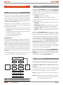

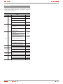
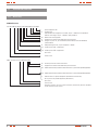


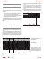
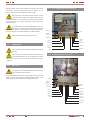
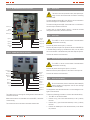
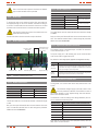


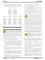
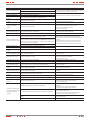


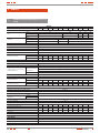
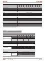


![[ITA] EVO DSP TM 10-30 kVA User Manual v. 2.0](http://vs1.manualzilla.com/store/data/006162882_1-9e3107de6287f10de27272cec5bbb519-150x150.png)


![[ENG] EVO DSP TM 10-30 kVA User Manual v. 2.0](http://vs1.manualzilla.com/store/data/005715238_1-26b73917878f712f842422018d03a475-150x150.png)