1
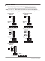
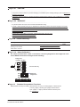
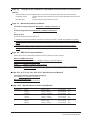
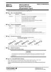
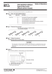
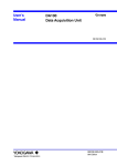
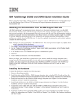
User’s
Manual
DA100
Data Acquisition Unit
Notice of Alterations
Please note the following(underlined) alterations to the IMDA100-01E.
Page 3 “Main Unit DA100”
Model
Suffix Code
··············
······························································
Type
-1························
-2························
-B························
-C························
-D························
-E························
-F························
-G························
-Q························
-R························
-T························
··············
Description
Stand-alone model
Expandable model
DU100-11 (Input module) and DT300-21 (Communication module) are attached
DU100-21 (Input module) and DT300-21 (Communication module) are attached
DU100-31 (Input module) and DT300-21 (Communication module) are attached
DU100-11 (Input module) and DT300-41 (Communication module) are attached
DU100-21 (Input module) and DT300-41 (Communication module) are attached
DU100-31 (Input module) and DT300-41 (Communication module) are attached
DU100-11 (Input module) and DT300-31 (Communication module)* are attached
DU100-21 (Input module) and DT300-31 (Communication module)* are attached
DU100-31 (Input module) and DT300-31 (Communication module)* are attached
* With Modbus communication function
······························································
Power Cord
D·········
F·········
R·········
S·········
H·········
W·········
Y·········
3-pin inlet w/UL, CSA cable (Part No. A1074WD)
3-pin inlet w/VDE cable (Part No. A1004WD)
3-pin inlet w/AS cable (Part No. A1024WD)
3-pin inlet w/BS cable (Part No. A1023WD)
3-pin inlet w/GB cable (complies with the CCC)(Part No. A1064WD)
No power cord, Screw terminal
No power cord, 2-pin round-type connector (only when power supply code is -2)
Page 3 “Subunit DS400/DS600”
Model
Suffix Code
··············
······························································
Power Cord
D·········
F·········
R·········
S·········
H·········
W·········
Y·········
Description
3-pin inlet w/UL, CSA cable
3-pin inlet w/VDE cable
3-pin inlet w/AS cable
3-pin inlet w/BS cable
3-pin inlet w/GB cable (complies with the CCC)
No power cord, Screw terminal
No power cord, 2-pin round-type connector (only when power supply code is -2)
Page 5 “Standard Accessories”
DA100-B, -C, -D, -E, -F, -G, -Q, -R, and -T are appended to the following accessories in addition to the
above-mentioned standard accessories by the customer of purchase.
Main Unit Type
Name
DA100-B
10-channel universal input module
DU100-11
RS-232-C module
DT300-21
RS-232-C cable
1
1
1
DA100-C
20-channel universal input module
DU100-21
RS-232-C module
DT300-21
RS-232-C cable
1
1
1
DA100-D
30-channel universal input module
DU100-31
RS-232-C module
DT300-21
RS-232-C cable
1
1
1
DA100-E
10-channel universal input module
Ethernet module
1
1
Yokogawa Electric Corporation
Model
DU100-31
DT300-41
Q'ty
IM DA100-01E-88 1/6
for IM DA100-01E 8th Edition
Main Unit Type
Name
Model
Q'ty
DA100-E
10-channel universal input module
Ethernet module
DU100-11
DT300-41
1
1
DA100-F
20-channel universal input module
Ethernet module
DU100-21
DT300-41
1
1
DA100-G
30-channel universal input module
Ethernet module
DU100-31
DT300-41
1
1
DA100-Q
10-channel universal input module
RS-422-A/RS-485 module
DU100-11
DT300-31
1
1
DA100-R
20-channel universal input module
RS-422-A/RS-485 module
DU100-21
DT300-31
1
1
DA100-T
30-channel universal input module
RS-422-A/RS-485 module
DU100-31
DT300-31
1
1
Note
When DA100-B, -C, -D, -E, -F, -G, -Q, -R, and -T are used while bought, the system need not be restructured.
However, when the position where the module is installed is changed or another module is installed, it is necessary to
restructure the system.
Page 6 “Optional Accessories”
Name
Model
Description
··············
··················
············································
AC adapter
DV500-001
DV500-002
DV500-003
DV500-004
DV500-005
2-pin inlet w/UL, CSA cable for DC100/DA100/DS400/DS600
2-pin inlet w/VDE cable for DC100/DA100/DS400/DS600
2-pin inlet w/AS cable for DC100/DA100/DS400/DS600
2-pin inlet w/BS cable for DC100/DA100/DS400/DS600
2-pin inlet w/GB cable (complies with the CCC) for DC100/DA100/DS400/DS600
Page 7 “Safety Precautions”
The following caution has been added.
CAUTION
This instrument is a Class A product. Operation of this instrument in a residential area may cause
radio interference, in which case the user is required to take appropriate measures to correct the
interference.
Page 1-11 “ DAQ Software 32 (standard accessory)” and “DAQ Software 32 Plus (special
order)”
The following five OS environment are supported.
• Windows 95
• Windows 2000
• Windows 98
• Windows XP
• Windows NT 4.0
Page 2-3 “Installation Method”
Panel installation
Attach the unit to the 2 mm-thick metal plate using the 6 screws included (length : 16 mm) according to the
figure below.
Page 2-14 “WARNING”
············································································································
• When 30 VAC or 60 VDC and more is applied to the output terminal of the alarm output module or the output
terminal of the DI/DO module, use double-insulated wires (withstand voltage performance: more than 2300
VAC) for those wires which apply 30 VAC or 60 VDC and more. All other wires can be basic-insulated
(withstand voltage performance: more than 1390 VAC). ··········································
• To prevent fire, use signal wires having a temperature rating of 75°C or more.
IM DA100-01E-88 2/6
for IM DA100-01E 8th Edition
Page 2-14 “CAUTION”
············································································································
• The overvoltage category of each input module is CAT ll (IEC61010-1, CSA22.2 No.61010-1).
• The measurement category of each input module is CAT ll (IEC61010-1, CSA22.2 No.61010-1).
Page 2-17, 2-18, 2-19 “Wiring Strain Input Signal Lines (to Strain Input Module)”
In the wiring diagrams of each gauge method, the wiring diagram for the bridge box used for
the DU500-14 has been changed to the following:
• Single-gauge method
• Single-gauge three-wire method
Bridge head
(701955 or 701956)
Bridge head
(701955 or 701956)
1
2
3
4
5
6
7
8
Rg
Bridge head
switch
ON
Bridge head
switch
ON
OFF
OFF
SW
1
2
3
4
5
6
7
8
Rg
SW
1 2 3 4 5
1 2 3 4 5
SW1 SW2 SW3 SW4 SW5
ON ON ON ON OFF
SW1 SW2 SW3 SW4 SW5
OFF ON ON ON OFF
• Adjacent-side two-gauge method
• Opposed-side two-gauge method
Bridge head
(701955 or 701956)
Bridge head
(701955 or 701956)
1
2
3
4
5
6
7
8
Rg1
Rg2
Bridge head
switch
ON
Rg1
Rg2
Bridge head
switch
ON
OFF
SW
1
2
3
4
5
6
7
8
OFF
1 2 3 4 5
SW
SW1 SW2 SW3 SW4 SW5
OFF ON ON ON OFF
1 2 3 4 5
SW1 SW2 SW3 SW4 SW5
ON OFF ON ON OFF
• Four-gauge method
Bridge head
(701955 or 701956)
Rg1
Rg4
Rg2
Rg3
1
2
3
4
5
6
7
8
Bridge head
switch
ON
OFF
SW
1 2 3 4 5
SW1 SW2 SW3 SW4 SW5
OFF OFF OFF ON OFF
IM DA100-01E-88 3/6
for IM DA100-01E 8th Edition
Page 2-21 “CAUTION”
············································································································
• The power monitor module is a product belonging to Installation (Over-voltage) Category CAT II (IEC61010-1,
CSA22.2 No.61010-1).
• The power monitor module is a product belonging to Measurement Category CAT II (IEC61010-1, CSA22.2
No.61010-1).
Page 2-26 “WARNING”
············································································································
• To prevent electric shock, do not touch the terminals after wiring.
• Furnish a switch (double-pole type) to separate the instrument from the main power supply in the power
supply line. In addition, make sure to indicate that the switch is a power control for the instrument on the
switch and the ON/OFF positions of the switch.
Switch Specifications
Steady-state current rating: 3 A or more, inrush current rating: 90 A or more
Use a switch complied with IEC60947-1, -3.
• Do not add a switch or fuse to the ground line.
Page 3-8 “Trouble Shooting”
Description
Cause
Action
The status indicator is
flashing in an interval
other than 1-second.
An internal error occurred.
Cut the power, wait for the instrument
to cool, then, turn the power back ON
again.
Reference
Page
2-25
Page 3-10 “About Calibration”
For “Strain measurement” under “Connection,” the wiring diagram for the bridge box used
for the DU500-14 has been changed to the following:
Bridge head
(701955 or 701956)
1
2
3
4
5
6
7
8
R2
R1
R4
R3
Connect CH2 only
Switch the
bridge head
ON
OFF
SW
1 2 3 4 5
SW1 SW2 SW3 SW4 SW5
OFF OFF OFF ON OFF
Page 4-3
Standard Computation Functions
Measurement accuracy for scaling : Measurement accuracy for scaling (digits) = Measurement
accuracy (digits) x Scaling span (digits) / Measurement
span (digits) + 2 digits (numbers below the decimal point
are rounded up).
IM DA100-01E-88 4/6
for IM DA100-01E 8th Edition
Page 4-5
Failure”
Changes to the contents of “Information on and Process in Case of Power
The DA makes a report immediately after it recovers from the power failure and then stops reporting.
Computing results:The DA computes data measured up to the point immediately before the power
failure.
Reporting time:
The time when the power failure occurred.
Page 4-7 “Normal Operation Conditions”
Installation category based on IEC61010-1, CSA22.2 No.61010-1
II*1
Pollution degree based on IEC61010-1, CSA22.2 No.61010-1
2*2
Warm-up time
At least 30 minutes after power switch-on.
*1 Describes a number which defines a transient overvoltage condition. It implies the regulation for impulse
withstand voltage. “II” applies to electrical equipment which is supplied from fixed installations like distribution
boards.
*2 Describes the degree to which a solid, liquid, or gas which deteriorates dielectric strength or surface
resistivity is adhering. “2” applies to normal indoor atmosphere. Normally, only non-conductive pollution
occurs.
Page 4-8 “EMC Conformity Standards”
Please refer to these specifications instead of the one printed in the user's manual.
Safety and EMC Standards
CSA
UL
C-Tick
KC marking
CSA22.2 No.61010-1, installation category II, pollution degree 2
UL61010-1 (CSA NRTL/C)
EN55011 compliance, Class A, Group 1
Electromagnetic wave interference prevention standard, electromagnetic wave protection standard compliance
Page 4-13, 4-17, 4-19, 4-21, 4-22, 4-29 “Specifications of Module”
Installation Category (Overvoltage Category)
CAT II (IEC61010-1, CSA22.2 No.61010-1)
Measurement Category
CAT II (IEC61010-1, CSA22.2 No.61010-1)
Page 14-18 “Specifications of Strain Input Module”
Gauge Method
Single-gauge
Two-gauge
Four-gauge
Measurement Range Type
2000µε
20000µε
200000µε
1000µε
10000µε
100000µε
500µε
5000µε
50000µε
Rated Measurement Range
-2000 to 2000µε
-20000 to 20000µε
-200000 to 200000µε
-1000 to 1000µε
-10000 to 10000µε
-100000 to 100000µε
-500 to 500µε
-5000 to 5000µε
-50000 to 50000µε
Accuracy
0.5% of Range
0.3% of Range
0.3% of Range
0.5% of Range
0.3% of Range
0.3% of Range
0.5% of Range
0.3% of Range
0.3% of Range
Resolution
0.1µε
1µε
10µε
0.1µε
1µε
10µε
0.1µε
1µε
10µε
IM DA100-01E-88 5/6
for IM DA100-01E 8th Edition
Page 4-19 “Specifications of Strain Input Module”
Accessory
Bridge head: 701955, 701956
Page 4-29 “Retransmission Module”
Load capacitance
0.22 µF or less
·································
Highest resolution
DT500-11: 12 bit (approx. 1.43 mV)DT500-21: 12 bit (approx. 5.86 µA)
IM DA100-01E-88 6/6
for IM DA100-01E 8th Edition