1
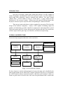
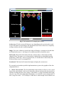
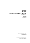
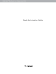
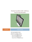
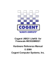
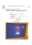
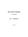
ELEN W4840 Embedded System Design
Final Project – “Button Hero”:
Initial Design
Spring 2007
March 22
Charles Lam (cgl2101)
Joo Han Chang (jc2685)
George Liao (gkl2104)
Ken Yu (khy2102)
INTRODUCTION
Our goal is to design a simple game engine that consists of a GPU (capable of
simple 2D graphics and animations used in the creation of game), an APU (capable of
music/sound effect playback), memory controller and software. The game, named
“Button Hero”, will be similar in style to “Guitar Hero”, a game created for the
PlayStation 2. The concept is simple – falling icons will represent different buttons that
the player will have to press at specific times corresponding to a musical selection.
There are two major tasks that we need to complete for our project. The first is the
design of the hardware component – namely a GPU capable of handling simple 2D
graphics and animations, an audio controller to output music and sound effects, and of
course the memory and CPU to store and process the software and data. The second is the
software aspect used for game logic, user interface, and data access/processing.
OVERALL ARCHITECTURE
Our macroscopic program architecture can be seen below:
FPGA
Memory
Controller
SRAM
Video
Controller
Buttons/Control
Serial I2C Bus
Interface
Video D/A
Converter
Audio Codec
(WM8731)
VGA Out
Line Out
Various BRAMs
SW Code
Sound files
Fig 1: Overall architecture diagram
We have chosen to omit the keyboard entirely, because the input can be handled by the
built-in push buttons on the Altera DE2. Using the keyboard will force us to incorporate
the UART and the software keyboard interface; while this could certainly be done, we
found no good reason to do the extra work since the push buttons add a console-like
flavor to the game and fit the name “Button Hero” perfectly. We’d like to stress that this
choice is not due to compromise. In fact, if time allows, we will consider building our
own console-like controller, rather than resorting to the keyboard. In either case, we will
need to make sure that the timings and communication between the interfaces is correct.
We have experience with both peripherals via past labs, which will be helpful.
For the sounds, we will write our own audio interface that will allow our game to both be
more entertaining and interactive. Depending on our progress, we will either make the
music interactive according to user input or will make the music play regardless, with just
a warning “beep” when the user makes a mistake.
Finally, the SRAM controller is expected to be straight forward. Given the limited
capacity of the SRAM, however, there is a possibility that we will need to use an
SDRAM, especially if we decide to use full-blown sound files such as WAV or MP3
Format. In that case, we will set out by trying to write our own interface driver for the 8M
X 16 SDRAM / 128M (shown below). We know that this will be one of the most difficult
parts of our design, however there would be no other alternative if the SRAM capacity
turns out to be not enough.
Fig 2. The pins for the SDRAM that need to be controlled by an interface driver
GRAPHIC ENGINE
There are multiple ways to implement the graphic engine for this project, Button Hero,
due to its characteristics. The goal is to obtain a runtime game screen that resembles the
following image:
Lifeboard
Action Area
Judge
Scoreboard
Fig 3. The breakdown of a sample game screen.
Action Area: The blue arrows fall down (or up, depending on the version) and we need
to press the button corresponding to the appropriate arrow when a blue arrow completely
overlaps with the red arrow in the background.
Judge: Every time a button is pressed, the Judge will display a comment to describe how
well-timed action was, i.e. the degree of overlap between the red and blue arrow.
Life board: This board will contain a life bar, as shown above, which starts out fully
charged at first. The game is over when the bar is depleted due to substandard gaming
performance. While Fig 2. shows a zigzag life bar, we feel that this is unnecessary and
will most likely resort to a rectangular bar.
Scoreboard: This board will contain four digits to display the current score.
We currently envision three possible implementations to process the graphics of the four
components above:
A – Worst Case Scenario. The first method that seems intuitive at first is to use a pixel
map for the entire display, which can be altered by software and stored in the memory for
repetitive loading onto the screen using a video buffer. A rough calculation shows that,
even if we use 256 colors rather than monochrome, we can fit the screen content in 640 X
480 X (log2256/8 bits) = 307.2 Kilobytes. While this is small enough for the SRAM even
considering the SW code and sound files (most likely MIDI format) that will also be
stored in the SRAM, and allows for a simple implementation almost entirely based on
software, we realize that it will be difficult to obtain a decent frame rate if we need to
reread and redraw 307.2KB/frame. Thus, this primitive implementation will only serve
as our fallback plan for the graphic engine.
B – Best Case Scenario. Instead, the optimal implementation that we imagine at this
point is the use of sprites. We can make use of the Block RAM, (BRAM) the easy-to-use
built-in memory that was utilized in Lab 1, to store the sprite data information:
Graphic types for various game elements:
Action Area
Falling Arrows: Sprite (64 X 64 X 256 Colors)
Background Arrows: Tiles
Judge
Text: Sprite (128 X 64 X Binary) with fade effect through software
Scoreboard
Background Board: Tile (640 X 36 X Binary or 256 Colors)
Score text: Sprite (18 X 18 X Binary) for each digit
Lifeboard
Background Board: Tile (640 X 36 X Binary or 256 Colors)
Life bar: Rectangle drawing algorithm from Lab 3
The fade effect for the text in the “Judge” area (e.g. the red label “MISSED!” in Fig 3.)
refers to the color of the text being controlled by the software; the information in the
BRAM will be binary, i.e. it will only indicate whether certain pixels are opaque or
transparent. An easy algorithm would be to use a for-loop to traverse various shades of
R/G/B for every X clock cycle from 0% to 100% opacity for fade-in effect, and from
100% to 0% for fade-out effect. We will need to calibrate the speed at which this is done
(clock frequency, X) after much of the implementation is completed. Furthermore, we
will need to watch out for floating-point calculation approximation errors; this can be
avoided by using additive integer increments for color selection.
With this design, we only need to keep track of the coordinate of each object rather than
reprocessing the entire 640 X 480 pixel map for every clock cycle. Implementing this
flexible engine, however, will certainly be a challenge given the timeline; while our
group will do our best to adhere to this original plan, we also propose another fallback
plan in case we run out of time that compromises the flexibility of the above
implementation but maintains the smoothness of the animation:
C – Reasonable Fallback Plan. This alternate video processing algorithm will be an
extension of the block moving algorithm used in Lab 3, exploiting the fact that the main
animation of concern in this project is the vertically falling arrow. Firstly, we will be
extending the algorithm to support more complicated shapes other than just a rectangle
(currently, we are thinking along the lines of an arrow or a circle). Secondly, given initial
conditions, the hardware, not software, will be moving the arrows – this we envision will
require two extra counters to keep track of icon location and to iterate after a certain
number of clock cycles. Thirdly, we will have multiple icons on the screen moving at
once so that there can be multiple arrows for each button. We are thinking right now a
minimum of eight icons.
Audio Engine
The audio portion of our program will consist of the audio interface/driver and the
speaker themselves. According to the DE2 User Manual, the DE2 board itself provides
the high-quality 24-bit audio via the Wolfson WM8731 audio CODEC. We will be using
the line-out port for the music. The WM8731 is controlled by a serial I2C bus interface
on the Cyclone II FPGA board we are using. It is designed with digital audio input word
lengths ranging from 16-32 bits and sampling rates from 8kHz to 96kHz.
We will be coding the driver interface for this audio device. When the game is started, a
hard-coded raw data song will be loaded into the SRAM. Upon the user specifying the
start of the game itself, the song will begin playing throughout the game. The SRAM data
is all we need because we have decided to not make the audio interactive, despite whether
or not the user correctly presses the buttons or not.
Fig 4. Wolfson WM8731 audio CODEC which will be used for BGM playback.
Data Structure & Algorithms
As stated before, the software will mostly be in for handling the game logic, user
interface, and data access/processing. That is, the game will be required to take game data
from the RAM (music data, which buttons fall down where, etc.) and send it to the
hardware. At the same time, the software needs to receive information from the hardware
(location of the arrow when the button was pushed) and using that information calculate
the resulting score and output it to the user.
Each “stage” of the game will have a corresponding music file (most likely MIDI, due to
its compact size and ease of playback) and “notes file,” which is a timeline of when the
arrows start to fall. This file will be arranged in chronological order using the following
format: (ARROWTYPE: 1 = Up Arrow, 2 = Down Arrow, 3 = Left Arrow, 4 = Right
Arrow)
CLOCKCYCLES
CLOCKCYCLES
CLOCKCYCLES
…
CLOCKCYCLES
ARROWTYPE
ARROWTYPE
ARROWTYPE
ARROWTYPE
e.g.
11
3000 2
6000 1
10000 3
10000 4
…
600000 1
603000 2
The above file should force the system to let UpArrow fall at Cycle 1, Down Arrow fall
at Cycle 3000, UpArrow fall at Cycle 6000, Left & RightArrow fall simultaneously at
Cycle 10000, and so on.
This data will most likely be hard-coded in the code, assuming that we won’t develop too
many game stages (i.e. <10); for full scalability, we will need to find a way for the user to
create custom stages. This, however, is subject to future development and is beyond the
scope of this project.
The “Judge” will also display a comment and assign an appropriate score / life bar
decrement depending on the quantitative degree of “overlap” between the red and blue
arrow at the time a button is pressed:
Vertical Overlap
Comment
Score
Life decrement
>=95%
PERFECT!
+3
0
>=90%
EXCELLENT!
+2
0
>=80%
GOOD
+1
0
>=70%
PASS
0
0
>=50%
BAD
0
-5%
<50%
MISS!
0
-10%
Table 1. A temporary scoring scheme subject to calibration
This information will also be hard-coded in. However, this table will be subject to further
calibration at the time of testing. We could also implement multiple levels of difficulty by
building more than one such table. The algorithm to determine the degree of overlap will
be a simple mathematical equation, and will only be concerned with the vertical overlap
since the horizontal overlap is always 100% as the arrows are falling downwards.
One aspect of the project that worries us most is the synchronization of music and
gameplay. Given the nature of the game, this fun is maximized when the arrows (icons)
fall down in a timely manner to match the beats of the background music. While we
currently expect that we will be able to achieve this synchronization by hard-coding, we
will need to go through an extensive testing after a full implementation to see if there are
any unexpected inconsistencies. If so, we plan to write a mathematical synchronization
algorithm that handles the frequency of the clock of the graphic engine to control the
speed of the animation in order to match the flow of the music.