1
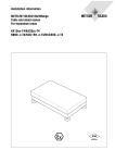
Installation Information
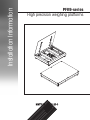
PFK9-series
High precision weighing platforms
Congratulations on choosing the quality and precision of METTLER TOLEDO. Proper
use of your new equipment according to this User manual and regular calibration and
maintenance by our factory-trained service team ensures dependable and accurate
operation, protecting your investment. Contact us about a service agreement tailored to
your needs and budget. Further information is available at
www.mt.com/service.
There are several important ways to ensure you maximize the performance of your
investment:
1. Register your product: We invite you to register your product at www.mt.com/productregistration so we can contact you about enhancements, updates and important notifications
concerning your product.
2. Contact METTLER TOLEDO for service: The value of a measurement is proportional
to its accuracy – an out of specification scale can diminish quality, reduce profits and
increase liability. Timely service from METTLER TOLEDO will ensure accuracy and
optimize uptime and equipment life.
–– Installation, Configuration, Integration and Training: Our service representatives are factory-trained, weighing equipment experts. We
make certain that your weighing equipment is ready for production in a cost
effective and timely fashion and that personnel are trained for success.
–– Initial Calibration Documentation: The installation environment and application requirements are unique for every
industrial scale so performance must be tested and certified. Our calibration
services and certificates document accuracy to ensure production quality and
provide a quality system record of performance.
–– Periodic Calibration Maintenance: A Calibration Service Agreement provides on-going confidence in your weighing
process and documentation of compliance with requirements. We offer a variety
of service plans that are scheduled to meet your needs and designed to fit your
budget.
2
PFK9-series 30233015B
Contents
1 Safety information for operation in the Ex area .....................................................4
2Installation...........................................................................................................6
2.1 Preparatory work...................................................................................................6
2.2 Setting up.............................................................................................................7
2.3Levelling............................................................................................................. 12
2.4 Pit installation...................................................................................................... 13
2.5 Lengthening and installing connection cable........................................................... 13
2.6 Equipotential bonding in hazardous areas.............................................................. 14
2.7 Connecting PFK98_APW weighing platforms.......................................................... 15
2.8Commissioning................................................................................................... 17
3 Configuration possibilities.................................................................................. 18
3.1 General information............................................................................................. 18
3.2 Configuration data in the factory setting................................................................. 19
4
4.1
4.2
4.3
4.4
Planning assemblies..........................................................................................20
Notes on planning............................................................................................... 20
Preload range...................................................................................................... 20
Mounting possibilities........................................................................................... 21
Opening possibilities............................................................................................ 25
5Dimensions........................................................................................................29
30233015B PFK9-series
3
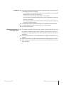
1 Safety information for operation in the
Ex area
▲▲ The PFK9-series high precision weighing platforms are approved for operation in Zone
2 (gases), Zone 22 (dusts) and DIV 2 hazardous areas. There is an increased risk
in injury and damage when using the explosion-protected weighing platforms in a
potentially explosive atmosphere. Special care must be taken when working in such
hazardous areas.
▲▲ Any protective foils present in the hazardous area, e.g. on the load plate, must always
be removed.
4
Competence
▲▲ In hazardous areas, the weighing platforms may only be installed, maintained and
repaired by authorized METTLER TOLEDO service personnel.
Ex approval
▲▲ No modifications may be made to the weighing platform and no repair work may be
performed on the system modules. Any weighing platform or system modules that are
used must comply with the specifications contained in the installation instructions.
Non-compliant equipment jeopardizes the intrinsic safety of the system, cancels the
"Ex" approval and renders any warranty or product liability claims null and void.
▲▲ The safety of the weighing system is only guaranteed when the weighing system is
operated, installed and maintained in accordance with the respective instructions.
▲▲ Also comply with the following:
–– the instructions for the system modules,
–– the regulations and standards in the respective country,
–– the statutory requirement for electrical equipment installed in hazardous areas in
the respective country,
–– all instructions related to safety issued by the owner.
▲▲ The explosion-protected weighing system must be checked to ensure compliance with
the requirements for safety before being put into service for the first time, following any
service work and every 3 years, at least.
Operation
▲▲ Prevent the build-up of static electricity. Always wear suitable working clothes when
operating or performing service work in a hazardous area. Avoid strong mechanical
rubbing of the powder-coated surfaces against any material when operating in
Zone 22.
▲▲ Do not use protective coverings for the devices.
▲▲ Avoid damage to the system components.
▲▲ If system damage occurs, the system must be put out of operation immediately.
▲▲ Damaged system components must be replaced immediately.
Safety information for operation in the Ex area
PFK9-series 30233015B
Installation
▲▲ Only install or perform maintenance work on the weighing system in hazardous areas
if the following conditions are fulfilled:
–– the intrinsically safe characteristic values and zone approval of the individual
components are in accord with one another,
–– the owner has issued a permit ("spark permit" or "fire permit"),
–– the area has been rendered safe and the owner's safety coordinator has confirmed
that there is no danger,
–– the necessary tools and any required protective clothing are provided (danger of
the build-up of static electricity).
▲▲ The certification papers (certificates, manufacturer’s declarations) must be present.
▲▲ Lay cabling fixed and securely, bending radius > 5 x cable diameter.
▲▲ Do not cut through cables.
Additional requirements for
Zones 2/22 or DIV 2
▲▲ The explosion protected PFK9-series high precision weighing platforms may only
be operated in hazardous areas of Zone 2 (gases), Zone 22 (dusts) and DIV 2 in
conjunction with weighing terminals that have the appropriate approval and interface
specification.
▲▲ The connection cable may not be separated from the weighing terminal while it is
energized.
▲▲ Tighten the knurled nut of the M12 connection cable with a tightening torque of 10 Nm.
▲▲ Before setting up the system secure the connection between weighing terminal and
weighing platform.
30233015B PFK9-series
Safety information for operation in the Ex area
5
2 Installation
2.1 Preparatory work
2.1.1 Selecting installation location
▲▲ The foundation at the installation location must be capable to safely support the
weight of the weighing platform at its support points when it carries the maximum
load. At the same time, it should be so stable that no vibrations occur during weighing
operations. These requirements also apply when the weighing platform is integrated in
conveying systems and the like.
▲▲ Ensure that the ground at the installation location is even.
▲▲ Ensure that there are no vibrations from machines near the installation site.
▲▲ Ensure that there are no drafts at the installation site.
2.1.2 Ambient conditions
• Use powder-coated/hot galvanized weighing platforms only in a dry environment.
• In a damp environment, in wet operation or when working with chemicals: Use
stainless-steel weighing platforms.
2.1.3 Accessories
➜➜ Completely unpack the accessories provided with the weighing platform.
–– 1 bottle of oil, suitable for foodstuffs
–– 1 set of measuring data signs for selectable configurations
–– Optional: ACC409xx-SICSpro-IDNet converter (incl. identcard kit)
additionally provided for sizes D, E, ES:
–– 4 eye bolts in a bag
additionally provided for weighing platforms with foldable load plate:
–– 2 eye bolts in a bag
–– 1 handle
6
Installation
PFK9-series 30233015B
2.2 Setting up
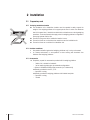
2.2.1 Size C
Setting up
CAUTION
Danger of injury due to the heavy load plate.
▲▲ Always ask a second person to help removing the load plate.
▲▲ Wear gloves when removing the load plate.
1
1. Remove the load plate by pivoting the two side handles (1) outward.
2. Lift the weighing platform off the transport pallet and set it down at the installation
location.
Be careful when lifting it off the pallet to prevent the lever mechanism which is open at
the bottom from being damaged.
3. Unscrew and remove the yellow locking screw (3).
4. Loosen the lever lock and remove the transport lock.
2
Note
Keep the locking elements for use for transporting the weighing platform in the future.
2
Routing the connection cable
The connection cable is stored inside the weighing platform during transport for protection.
1. Route out the connection cable under the base frame.
2. Replace the load plate (3) so that the symbol is located above the level indicator.
3. Make sure that the load supports (4) in the corners of the weighing platform are
vertical.
3
30233015B PFK9-series
Installation
7
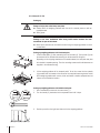
2.2.2 Sizes D / E / ES
Setting up
CAUTION
Danger of injury due to the heavy load plate.
▲▲ Always move the weighing platforms with the aid of a second person or with an
appropriate tool.
▲▲ Wear gloves.
NOTICE
Damage to the lever mechanism when using forklift trucks because the lever
mechanism is open at the bottom.
▲▲ Move up the load forks of the forklift truck and hang the weighing platform on them
as described.
2
3
4
1
Setting up weighing platforms with fixed load plate
1. Lift off the load plate (1) after unscrewing the 6 or 8 screws (2). The eye bolts (3) can
be screwed into the threads after removing the blind screws as lifting aid.
Depending on the shipping warehouse or the model ordered, the load plate may also
be included in separate packing. Then the mounting screws and the blindscrews are
supplied in the accessories bag.
1
4
2
2. Lift the weighing platform off the transport pallet. To do this, screw the four eyebolts
(4) provided into the threads at the corners of the load plate mounting device and lift
off the weighing platform with a crane, block and tackle or similar equipment and set
it down at the installation location.
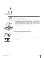
Setting up weighing platforms with foldable load plate
1. Use a screwdriver to screw out the cover screw (1).
2. Turn the handle (2) clockwise into the exposed thread until it stops.
3. Position yourself on the right-hand side next to the weighing platform.
8
Installation
PFK9-series 30233015B
4. Pull the load plate up using the handle.
DANGER
Danger of injury due to shutting load plate.
▲▲ Ensure that the pneumatic spring has extended completely.
5. Lift the weighing platform off the transport pallet. To do this, screw the two eyebolts
(3) provided (they are located on the inside on the level indicator side) into the
threads of the load frame and lift off the weighing platform with a crane, block and
tackle or similar equipment and set it down at the installation location.
6. Remove the eye bolts.
3
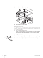
Releasing lift-off locks and removing transportation locks
1. Loosen the nuts (1) at all 4 corners.
2 1
1 mm
30233015B PFK9-series
2. Screw up the locking screws (2) and adjust evenly to approx. 1 mm clearance at all
4 corners.
3. Retighten the nuts (1).
Installation
9
4. Remove the lever lock (3) by unscrewing 2 screws.
5. Remove the transportation lock (4).
3
4
6. Mount the lever lock (3) with 2 screws.
Routing the connection cable
The connection cable (1) is stored inside the weighing platform during transport for
protection. Depending on the conditions at the installation location, the connection cable
can be routed out as follows:
• Below the weighing platform on the floor Ideal with the recessing installation of the weighing platform. In the case of above-floor
installation protective cable bridges can be laid up to under the weighing platform.
• Through the base frame 2
3
1
10
Installation
1. Remove the rubber grommet (2) from the hole (3) in the base frame and pull through
the connection cable (1).
2. Push the slotted rubber grommet (2) over the cable and insert it in the hole (3).
PFK9-series 30233015B
4
5
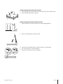
Closing weighing platforms with fixed load plate
1. Put on the load plate (4) and mount it with the screws (5) (quick-release locks).
2. Screw the blind screws into the threads.
Closing weighing platforms with foldable load plate
1. Position yourself on the right-hand side next to the weighing platform.
2. Press the load plate down using the handle.
1
30233015B PFK9-series
2
3. Ensure that the load plate latches in and lies evenly on the load frame.
4. Turn out the handle (1) counter-clockwise.
5. Screw the cover screw (2) into the load plate.
Installation
11
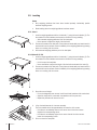
2.3 Levelling
Notes
• Only weighing platforms that have been levelled precisely horizontally provide
accurate weighing results.
• Redo levelling when the weighing platform has been moved.
1
2
2
1
2.3.1 Size C
1. Level the weighing platform with the 4 foot bolts (1) using the level indicator (2): The
air bubble of the level indicator must come to rest within the ring marking.
–– With recessed weighing platforms lift off the load plate.
–– Use a spanner to adjust the height of the foot bolts.
2. Ensure even contact of the foot bolts. Every foot must stand safely and must have full
contact with its entire surface. Check the stability of the weighing platform by pressing
down on or rocking it at the corners.
3. With recessed weighing platforms put on the load plate.
2.3.2 Sizes D / E / ES
1. Level the weighing platform with the 4 foot bolts (1) using the level indicator (2): The
air bubble of the level indicator must come to rest within the ring marking.
–– Lift off or open the load plate.
–– Use a screwdriver to adjust the height of the foot bolts underneath the holes (3).
2. Ensure even contact of the foot bolts. Every foot must stand safely and must have full
contact with its entire surface. Check the stability of the weighing platform by pressing
down on or rocking it at the corners.
3
3
II
III
I
3. Check the over all height.
–– Put a ruler diagonally over corners I and III and check levelness with a water level.
–– Adjust the height of the cornes with a screwdriver until they are even.
–– Repeat this procedure for cornes II and IV.
IV
4. Lift up the load frame at all 4 corners manually.
The force needed should be approximately the same for all 4 corners.
–– If the force is considerably lower at one corner than at the other corners:
Heighten the corresponding corner.
–– If the force is considerably higher at one corner than at the other corners:
Lower the corresponding corner.
5. Put on or close the load plate.
12
Installation
PFK9-series 30233015B
2.4 Pit installation
The mounting material and detailed instructions for constructing the pit are included with
the "Quick pit for PFK9-series, size C" or "Quick pit for PFK9-series, sizes D / E / ES"
installation kit. The proper construction of the pit according to these instructions is a
requirement.
2.4.1 Size C
1. Carefully lower the weighing platform into the pit. When doing so, also pull the cable
into the empty pipe or cable conduit.
2. Adjust the height of the support feet so that the load plate is flush with the floor.
2
2.4.2 Sizes D / E / ES
1. Lift off or open the load plate and route out the connection cable under the weighing
platform, see Section 2.2.2.
2. Slowly lower the weighing platform into the pit by the eye bolts. When doing so, also
pull the cable into the empty pipe or cable conduit.
3. Release the lift-off lock, see Section 2.2.2.
4. Adjust flushness with the floor. To do this, lay spacers (size D: 6 mm, sizes E / ES: 8 mm) on the load frame at the
corners and adjust flush with the upper edge of the pit frame. Adjust the height of the support feet.
5. To level, see section 2.3.2.
6. Center the weighing platform in the pit with 6 or 8 clamping screws (1) and clamp
them firmly in place. Lock the bolts (1) on the inside of the base frame with the
nuts (2).
7. Either put on the load plate and screw on firmly or fold down the load plate.
1
2.5 Lengthening and installing connection cable
The connection cable may be lengthened.
Standard version up to 100 m
Ex version
up to 50 m
➜➜ Route the connection cable directly out of the weighing platform to the weighing
terminal or the ConBloc (PBK98_APW weighing platforms only).
CAUTION
If the cable is laid in a pipe, ensure that the pipe is of a sufficient diameter.
30233015B PFK9-series
Installation
13
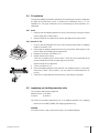
2.6 Equipotential bonding in hazardous areas
The equipotential bonding must be installed by a professional electrician when using the
weighing platform in hazardous areas. METTLER TOLEDO Service only has a monitoring
and consulting function here.
➜➜ Connect equipotential bonding (PA) of all devices (weighing platform and service
terminal) in accordance with the country-specific regulations and standards. In the
process, make sure that all device housings are connected to the same potential via
the PA terminals.
Location of the equipotential bonding clamp for size C
➜➜ Mount the equipotential bonding clamp on the base frame alongside the load cell.
1
Location of the equipotential bonding clamp for size D / E / ES
➜➜ Mount the equipotential bonding clamp (1) on the base frame.
1
5
4
9
10
1
6
2
7
8
3
Equipotential bonding clamp
1 Serrated lock washer A 4.3 DIN 6798
2 Serrated lock washer A 5.3 DIN 6798
3 Hexagonal lock nut M4 DIN 934
4 Washer 5.3 DIN 125, 2 pcs
5 Cheese head screw M5x16 DIN 912
6 Base frame
7 Hexagonal lock nut M5 DIN 934
8 Washer 4.3 DIN 125
9 Equipotential bonding clamp
10 Equipotential bonding plate
Mounting materials are enclosed with the weighing terminal for hazardous areas, e.g.
IND690xx.
14
Installation
PFK9-series 30233015B
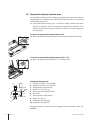
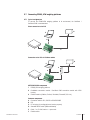
2.7 Connecting PFK98_APW weighing platforms
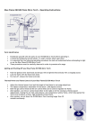
2.7.1 Typical configurations
To connect the PFK98-APW weighing platform to its environment, the ConBlock /
ConBlock IP66 is recommended.
Direct connection to the PLC
B
C
D
1
A
2
Connection to the PLC via Fieldbus module
B
C
3
D
F
1
2
E
METTLER TOLEDO components
1 PFK98_APW weighing platform
2 ConModule connection module / ConBlock IP66 connection module with IP66
housing
3 Fieldbus module (Profibus, Profinet, DeviceNet, Ethernet/IP, CC-Link)
Customer components
A Connection cable to PLC, RS232 or RS422/RS485
B PLC
C PC or laptop (for configuration and service purpose)
D Standard RS232 cable (DB9 male/female)
E Cable, 1 m, D-Sub 9 male <–> open ends
F Fieldbus cable
30233015B PFK9-series
Installation
15
2.7.2 Installation with weighing platforms used in hazardous areas
EXPLOSION HAZARD
ConBlock / ConBlock IP66 is not approved for hazardous areas.
▲▲ Only install the ConBlock / ConBlock IP66 in the safe area.
▲▲ Always use a suitable safety barrier to separate equipment located in the hazardous
area from the safe area.
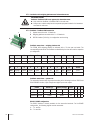
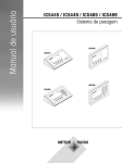
2.7.3 ConBlock / ConBlock IP66 connection
1 System connection side: 10 terminals
2 Weighing platform connection side: 2 x 10 terminals
3 RS232 interface (D-Sub 9), for configuration and servicing
1
2
ConBlock connections – weighing platform side
The PFK98_APW weighing platform is delivered with a 12 wire open end cable. The
corresponding terminals of the ConBlock are identified by the wire color and the respective
pin designation.
3
Pin
J
D
H
T
F
K
G
E
A
O
Color
–
–
–
–
–
–
–
–
white
brown and green
Signal
–
–
–
–
–
–
–
–
V DC
GND
Pin
L
U
P
C
R
B
S
N
M
Shield
Color
orange
black
purple
violet
blue
red
grey
pink
yellow
braid
Signal
Tx+
Rx+
Tx–
Rx–
CTS
GND INT
RTS
RXD
TXD
Shield
ConBlock connections – system side
The connection terminal strip is grouped according to the following functions: RS232 and
RS422/RS485 interface, input voltages and digital inputs and outputs.
RS232
RS422 (in)
RS422 (through)
Power
–
–
–
RXD
RTS
Rx+
Tx+
Rx+
Tx+
V DC
–
–
–
TXD
CTS
Rx–
Tx–
Rx–
Tx–
GND
–
–
–
GND INT
Shield
PE
–
–
–
Shield
Shield
RS422 / RS485 configuration
The RS422 interface is directly avalable via the connection terminals. For the RS485
configuration, the following signals must be connected:
A–: Tx– and Rx–
B+: Tx+ and Rx+
16
Installation
PFK9-series 30233015B
Load cell connector
Connector M12
Pin
Load cell signal
Color
1
V DC in
White
2
GND in
Brown
3
GND in
Green
4
TXD (RS232)
Yellow
5
RTS (RS232)
Grey
6
RXD (RS232)
Pink
7
CTS (RS232)
Blue
8
GND (RS232)
Red
9
TX+ (RS422)
B+ (RS485
Orange
10
TX– (RS422)
A– (RS485)
Purple
11
RX+ (RS422)
B+ (RS485
Black
12
RX– (RS422)
A– (RS485)
Violet
Shield
Braid
2.8 Commissioning
2.8.1 Switching on
➜➜ Switch on the weighing system at the final location only.
When switching on the weighing system for the first time, it will perform an automatic
geo code adjustment using the calibration weight which is integrated in the load cell.
2.8.2 PBK9APW-series adjustment
In order to reach maximum precision, the weighing platforms of the PBK9APW-series
must be adjusted according to the following sequence:
1. Perform an internal adjustment using SICS command C9.
2. For a user specific adjustment use the following SICS commands: C1, C2, C6, C8.
Note
This sequence is automatically performed if you do adjustment with the "Test & Adjustment"
menu of the "APW-Link" software.
30233015B PFK9-series
Installation
17
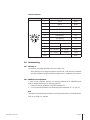
3 Configuration possibilities
3.1 General information
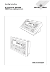
3.1.1 MultiInterval
MultiInterval precision means automatic switchover of the numerical increment (readability)
in dependence on the applied load.
Numerical
increment
0 Load weighed
max.
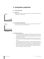
3.1.2 Single Range and High Resolution
Single Range and High Resolution mean that the numerical increments (readability)
remain the same across the entire weighing range.
Numerical
increment
0 Load weighed
max.
3.1.3 Additional setting options
• All other adjustment variables (adjustment to the weighing process and vibrations, as
well as adjustment of stability monitoring and the zero point correction) are adjusted
to the usual user conditions, however, they can be changed in the Scale menu of the
weighing terminal if necessary.
• When ordering the IDNet option, the ACC409xx-SICSpro-IDNet converter including the
identcard kit and a set of measuring data signs for the selectable configurations is
delivered.
• If the standard configuration does not meet your needs, it is possible to reconfigure the
weighing platform with the terminal. To do this, see the terminal operating instructions.
• Apply the selected configuration corresponding to the factory-mounted measuring
data sign to the Identcard, and the Max-Min sign near the IDNet terminal display.
• When the configuration is changed, it is also possible to change the preload range in
addition to the weighing range and the readability.
18
Configuration possibilities
PFK9-series 30233015B
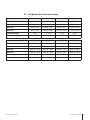
3.2 Configuration data in the factory setting
PFK989-
C300
C600
D600
D1500
300 kg
600 kg
600 kg
1500 kg
Max1 / e1
100 kg / 10 g
200 kg / 20 g
200 kg / 20 g
500 kg / 50 g
Max2 / e2
200 kg / 20 g
500 kg / 50 g
500 kg / 50 g
1000 kg / 100 g
Max3 / e3
300 kg / 50 g
600 kg / 100 g
600 kg / 100 g
1500 kg / 200 g
Zero-setting range
± 6 kg
± 12 kg
± 12 kg
± 30 kg
Preload range (typical)
54 kg
108 kg
108 kg
270 kg
E1500
E3000
ES1500
ES3000
1500 kg
3000 kg
1500 kg
3000 kg
Max1 / e1
500 kg / 50 g
1000 kg / 100 g
500 kg / 50 g
1000 kg / 100 g
Max2 / e2
1000 kg / 100 g
2000 kg / 200 g
1000 kg / 100 g
2000 kg / 200 g
Max3 / e3
1500 kg / 200 g
3000 kg / 500 g
1500 kg / 200 g
3000 kg / 500 g
± 30 kg
± 60 kg
± 30 kg
± 60 kg
270kg
540 kg
270kg
540 kg
Maximum capacity
PFK98_Maximum capacity
Zero-setting range
Preload range (typical)
30233015B PFK9-series
Configuration possibilities
19
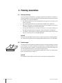
4 Planning assemblies
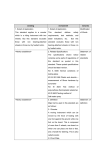
4.1 Notes on planning
Due to their design characteristics, the weighing platforms are suitable for installation in
conveying systems. The following specifications and dimensional drawings form the basis
for the design of the required assemblies.
• The weighing platform may only be supported by the support feet, and never by the
frame or lever parts.
• The weighing platform may only be permanently installed on the support feet.
• Moving or rotating parts on the weighing platform must be designed so that they do
not affect the weighing result. Balance rotating parts.
• The load plate must be free on all sides so that there is no connection between the
load plate and permanently mounted parts, even by falling parts or dirt deposits.
• Lay cables or hoses between the weighing platform and other machine parts so that
they do not exert any force on the weighing platform.
CAUTION
When mounting assemblies, make sure that no metal chips get into the weighing platform.
➜➜ Remove the load plate rfrom the weighing platform before working on the load plate.
4.2 Preload range
The weight of the structural parts permanently mounted on the weighing platform is referred
to as "preload". The preload is electrically compensated in the weighing platform so that
the full weighing range is available. The maximum preload (or the zero-setting range) that
can be compensated dispends on the configured weighing range.
For the preload range of the individual weighing platform refer to section "3.2 Configuration
data in the factory setting" on page 19.
CAUTION
The assemblies must already be mounted when connecting the weighing platform.
20
Planning assemblies
PFK9-series 30233015B
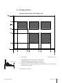
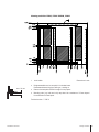
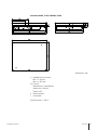
4.3 Mounting possibilities
Mounting possibilities PFK98_-C300 / PBK998_-C600
L
max. 7 mm
Level bubble
Dimensions in mm
• Bridge assemblies can be mounted in the shaded areas.
Recommended mounting type: Bolting on, welding on.
• Remove the load plate and drill through for this purpose.
• Mounting parts (e.g. bolts and nuts) may extend to a maximum of 7 mm beyond the
underside of the load plate.
Technical version: 11/2014
30233015B PFK9-series
Planning assemblies
21
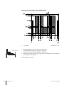
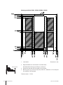
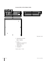
Mounting possibilities PFK98_-D600 / PBK998_-D1500
L
max. 10 mm
Level bubble
Dimensions in mm
• Bridge assemblies can be mounted in the shaded areas.
Recommended mounting type: Bolting on, welding on.
• Remove the load plate and drill through for this purpose.
• Mounting parts (e.g. bolts and nuts) may extend to a maximum of 10 mm beyond
the underside of the load plate.
Technical version: 11/2014
22
Planning assemblies
PFK9-series 30233015B
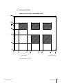
Mounting possibilities PFK98_-E1500 / PBK998_-E3000
L
max. 10 mm
Level bubble
Dimensions in mm
• Bridge assemblies can be mounted in the shaded areas.
Recommended mounting type: Bolting on, welding on.
• Remove the load plate and drill through for this purpose.
• Mounting parts (e.g. bolts and nuts) may extend to a maximum of 10 mm beyond
the underside of the load plate.
Technical version: 11/2014
30233015B PFK9-series
Planning assemblies
23
Mounting possibilities PFK98_-ES1500 / PBK998_-ES3000
L
max. 10 mm
Level bubble
Dimensions in mm
• Bridge assemblies can be mounted in the shaded areas.
Recommended mounting type: Bolting on, welding on.
• Remove the load plate and drill through for this purpose.
• Mounting parts (e.g. bolts and nuts) may extend to a maximum of 10 mm beyond
the underside of the load plate.
Technical version: 11/2014
24
Planning assemblies
PFK9-series 30233015B
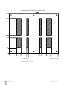
4.4 Opening possibilities
Opening possibilities PFK98_-C300 / PBK998_-C600
L
Level bubble
Dimensions in mm
Technical version: 11/2014
30233015B PFK9-series
Planning assemblies
25
Opening possibilities PFK98_-D600 / PBK998_-D1500
L
Level bubble
Dimensions in mm
Technical version: 11/2014
26
Planning assemblies
PFK9-series 30233015B
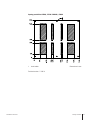
Opening possibilities PFK98_-E1500 / PBK998_-E3000
L
Level bubble
Dimensions in mm
Technical version: 11/2014
30233015B PFK9-series
Planning assemblies
27
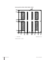
Opening possibilities PFK98_-ES1500 / PBK998_-ES3000
L
Level bubble
Dimensions in mm
Technical version: 11/2014
28
Planning assemblies
PFK9-series 30233015B
5 Dimensions
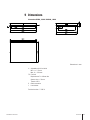
Dimensions PFK98_-C300 / PBK998_-C600
Dimensions in mm
H
FS
C
L
Adjustable with 4 foot bolts
Min. H = 115 mm
Max. H = 140 mm
Foot bolt
Required area D = 40 mm dia.
Spanner size = 19 mm
Thread = M10
Cable connection
Level bubble
Technical version: 11/2014
30233015B PFK9-series
Dimensions
29
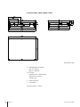
Dimensions PFK98_-D600 / PBK998_-D1500
Dimensions in mm
H
FS
C
L
Adjustable with 4 foot bolts
Min. H = 180 mm
Max. H = 205 mm
Foot bolt
Required area D = 60 x 60 mm.
Spanner size = 30 mm
Thread = M12
Cable connection
Level bubble
Technical version: 11/2014
30
Dimensions
PFK9-series 30233015B
Dimensions PFK98_-E1500 / PBK998_-E3000
Dimensions in mm
H
FS
C
L
Adjustable with 4 foot bolts
Min. H = 182 mm
Max. H = 207 mm
Foot bolt
Required area D = 60 x 60 mm
Spanner size = 30 mm
Thread = M12
Cable connection
Level bubble
Technical version: 11/2014
30233015B PFK9-series
Dimensions
31
Dimensions PFK98_-ES1500 / PBK998_-ES3000
Dimensions in mm
H
FS
C
L
Adjustable with 4 foot bolts
Min. H = 197 mm
Max. H = 222 mm
Foot bolt
Required area D = 60 x 60 mm
Spanner size = 30 mm
Thread = M12
Cable connection
Level bubble
Technical version: 11/2014
32
Dimensions
PFK9-series 30233015B
www.mt.com/support
Mettler-Toledo (Albstadt) GmbH
D-72458 Albstadt
Tel. + 49 7431-14 0
Fax + 49 7431-14 232
www.mt.com
Subject to technical changes
© Mettler-Toledo (Albstadt) GmbH 07/2015
30233015B en
For more information
*30233015B*
* 3 0 2 3 3 0 1 5 B *