1
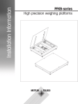
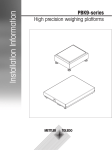
Installation information
METTLER TOLEDO MultiRange
Floor scales / Pit scales
For hazardous areas
KC300..x-T4/KCS300..x-T4
KC600..x-T4/KCS600..x-T4
KD600..x-T4/KD1500..x-T4
KE1500..x-T4/KE3000..x-T4
KES1500..x-T4/KES3000..x-T4
KG3000..x-T4/KG6000..x-T4
KN1500..x-T4
Floor scales / Pit scales
Contents
Contents
Page
1
Safety precautions .......................................................................
2
2.1
2.2
2.3
2.4
Installation.................................................................................. 4
Preparatory work .......................................................................... 4
Setting up and levelling ................................................................. 4
Installing connection cable ............................................................ 10
Pit installation .............................................................................. 12
3
3.1
3.2
Configuration possibilities ........................................................... 14
General information ...................................................................... 14
Configuration data ........................................................................ 15
4
4.1
4.2
4.3
4.4
Planning assemblies ...................................................................
Notes on planning ........................................................................
Preload range ..............................................................................
Mounting possibilities ...................................................................
Opening possibilities .....................................................................
5
Dimensions ................................................................................. 32
Installation information 22006746A 04/04
2
17
17
18
19
26
1
Safety precautions
Floor scales / Pit scales
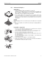
1 Safety precautions
There is an increased danger of injuries and damage when using the K...x-line
weighing platforms in hazardous areas.
Special care must be taken when working in such hazardous areas. The code of
practice is oriented to the "Safe Distribution" concept drawn up by METTLER TOLEDO.
The K...x-line weighing platforms with the measuring cells TBrick 15-Ex or TBrick 32Ex are admitted when using in the following domains:
Classification according to CENELEC
II 2 G/D EEx ib IIC T4
Classification according to FM
Class I, II, III Division 1, Group A – G
Competence
▲ The K...x-line weighing platforms may only be installed, maintained and repaired
by authorised METTLER TOLEDO service personnel.
Ex approval
▲ No modifications may be made to the device and no repair work may be
performed on the modules. Any weighing platforms or system modules that are
used must comply with the specifications. Non-compliant equipment jeopardises
the intrinsic safety of the system, cancels the Ex approval and renders any
warranty or product liability claims null and void.
▲ The safety of the weighing system is only guaranteed when the weighing system
is operated, installed and maintained in accordance with the respective instructions.
▲ Also comply with the following:
– the instructions for the system modules,
– the relevant national regulations and standards,
– the applicable statutory requirements for electrical equipment installed in
hazardous areas in the respective country,
– all instructions related to safety issued by the owner.
▲ The explosion-proof weighing system must be checked to ensure compliance
with the safety requirements before being put into service for the first time,
following any service work and at least every 3 years.
Operation
▲ Prevent the build-up of static electricity. Always wear suitable working clothes
when operating or performing service work in a hazardous area.
▲ Do not use protective covers with the devices.
▲ Any protective foils possibly present on the load plate have to be removed prior to
the first startup.
▲ Prevent damage to the weighing platforms.
2
Installation information 22006746A 04/04
Safety precautions
Floor scales / Pit scales
Installation
▲ Only install or perform maintenance work on the weighing system in the
hazardous area if the following conditions are fulfilled:
– the owner has issued a permit ("spark permit" or "fire permit"),
– the area has been rendered safe and the owner's safety co-ordinator has
confirmed that there is no danger,
– the necessary tools and any required protective clothing are provided (danger
of the build-up of static electricity).
▲ The certification papers (certificates, manufacturer’s declarations) must be present.
▲ Lay cables in such a way that they are protected from damage.
▲ Only route cables into the housing of the system modules via the suitable gland
and ensure proper seating of the seals.
Installation information 22006746A 04/04
3
Installation
2
Floor scales / Pit scales
Installation
2.1
2.1.1
Preparatory work
Selecting installation location
▲ The foundation at the installation location must be capable of safely support the
weight of the weighing platform at its support points when it carries the
maximum load. At the same time, it should be so stable that no vibrations occur
during weighing operations. These requirements also apply when the weighing
platform is integrated in conveying systems and the like.
▲ Ensure that vibrations due to machines near the installation site are kept to a
minimum.
2.1.2
Ambient conditions
• Use powder-coated/enamelled weighing platforms only in a dry environment.
• In a damp environment, in wet operation or when working with chemicals: Use
stainless-steel weighing platforms.
2.1.3
Accessories
➜ Completely unpack the accessories provided with the weighing platform.
– 1 Identcard
– 1 Set of signs for selectable configurations
additionally provided for KD...x, KE...x, KES...x:
– 4 Eye bolts in bag
additionally provided for KE...skx, KES...skx:
– 2 Eye bolts in bag
– 1 Special key
– 1 Universal oil
additionally provided for KN...x:
– 2 Eye bolts with nuts
– 1 Set of mounting parts for screwing on the floor
2.2
2.2.1
1
2
4
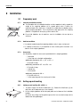
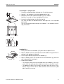
Setting up and levelling
Setting up and levelling KC...x/KCS...x
1. To reduce weight, first lift off the load carrier (1). Fold out the lift-off locks (2) on
both faces of the load carrier to use as handles.
2. Lift the weighing platform off the transport pallet and set down at the installation
location.
Be careful when lifting it off the pallet to prevent the lever mechanism open at the
bottom from being damaged.
Installation information 22006746A 04/04
Installation
Floor scales / Pit scales
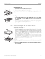
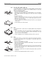
Releasing transport lock
3
1. Unscrew and remove the yellow locking screw (3).
4
2. Unscrew the yellow angled locking bracket (4).
Keep the locking elements for use when transporting the weighing platform in the
future.
Levelling
1. Level the weighing platform with the four foot bolts (6) using the level indicator
(5): The air bubble of the level indicator must come to rest in the centre of the
ring marking.
5
2. Ensure even contact of the foot bolts. Check the stability of the weighing platform
by pressing down on or rocking it at the corners.
6
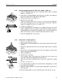
2.2.2
Setting up and levelling KD...x/KE...x/KE...skx/KES...x/KES...skx
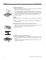
Setting up KD...x/KE...x/KES...x
1. Lift off the load plate (1) after unscrewing the 6 or 8 screws (2). The eye bolts
(3) can be screwed into the threads after removing the blind screws as lifting aid.
Depending on the shipping warehouse or the model ordered, the load plate may
also be included in separate packing. Then the mounting screws and the blind
screws are supplied in the accessories bag.
2
3
4
1
4
2. Lift the weighing platform off the transport pallet. To do this, screw the four eye
bolts (4) provided into the threads at the corners of the load plate mounting
device and lift off the weighing platform with a crane, block and tackle or similar
equipment and set it down at the installation location.
CAUTION
Danger of damage to the lever mechanism open at the bottom when using forklift
trucks.
➜ Move up the load forks of the forklift truck and hang the weighing platform on
them as described.
Installation information 22006746A 04/04
5
Installation
Floor scales / Pit scales
Setting up KE...skx/KES...skx
1. Open the two quick release locks with the special key and fold up the load plate
(special key is used as a aid when lifting off).
2. Lift the weighing platform off the transport pallet. To do this, screw the two eye
bolts (1) provided (they are located on the inside on the level indicator side) into
the threads of the load frame and lift off the weighing platform with a crane, block
and tackle or similar equipment and set it down at the installation location.
1
3. Remove the eye bolts.
CAUTION
Danger of damage to the lever mechanism open at the bottom when using forklift
trucks.
➜ Move up the load forks of the forklift truck and hang the weighing platform on
them as described.
Releasing the lift-off locks: KD...x/KE...x./KE...skx/KES...x/KES...skx
1. Loosen the nuts (1) at all four corners. Screw up the locking screws (2) and
adjust evenly to approx. 1 mm clearance at all four corners.
2. Retighten the nuts (1).
2 1
1 mm
Levelling KD...x/KE...x/KE...skx/KES...x/KES...skx
➜ Level the weighing platform with the 4 levelling feet (2) using the level indicator
(1): The air bubble of the levelling indicator must be located within the ring
marking.
The levelling feet can be adjusted with a 30 mm open-end spanner. Ensure even
contact of the levelling feet.
1
2
6
Installation information 22006746A 04/04
Installation
Floor scales / Pit scales
2.2.3
Setting up and levelling KG...x
Setting up KG...x
1. Lift off the load plate (1) after unscrewing the 12 screws (2).
Depending on the shipping warehouse or the model ordered, the load plate may
also be included in separate packing. If this is the case, the mounting screws
and the blind screws are supplied in the accessories bag.
2
1
2. Lift the weighing platform off the transport pallet. For this purpose, fasten a rope
or chain to the load frame (3) and lift the weighing platform off the transport
pallet with a crane, block and tackle or similar equipment, and set it down at the
setup location.
3
CAUTION
Danger of damage to the lever mechanism open at the bottom when using forklift
trucks.
➜ Move up the load forks of the forklift truck and hang the weighing platform as
described.
Loosening KG...x transport locks
1
1mm
1. Unscrew the yellow load-frame fastening nuts (1) at all four corners. Adjust to
1 mm clearance by screwing upward and then lock.
2. Loosen both locked yellow locking nuts (2) and screw upward approx. 2 mm.
3. Unscrew the yellow locked locking nuts (3) at the stop.
First screw the lower one downward until the knife edge (4) at the lever rests in
the suspended bearing.
Then set the upper and lower locking nuts (3) to approx. 1 mm clearance from
the stop pin (5) and lock.
5
4. Set both locking nuts (2) to approx. 1 mm clearance and lock.
3
5. Perform final inspection: All levers must have 0.2 mm to 0.3 mm clearance in
the axial direction. Readjust the stops if necessary.
2
3
1mm
1mm
5
4
Installation information 22006746A 04/04
7
Installation
Floor scales / Pit scales
Levelling KG...x
1. Evenly screw out the four foot bolts (1) at the corners approx. 3 turns.
2
2. Unscrew the inner support bolts (2) completely.
3. Place the bubble level on the long side with the level indicator, and level this side
with the foot bolts (1) on the left and on the right.
4. Place the bubble level on both short sides alternately and level these sides with
the other two foot bolts until the level indicator (3) and the bubble level match.
1
5. Perform final inspection: When the levelling is correct, the load frame (4) must
rest snugly in the bases at all four corners. Ensure even contact of the foot bolts.
Check the stability of the weighing platform by pressing down on it or rocking it at
the corners.
3
6. Screw both support bolts (2) downward until they touch the surface, tighten with
approx. 1/2 turn and lock.
1
4
3
1
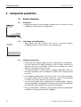
2.2.4
Setting up and levelling KN...x
Setting up KN...x
1. Unscrew the four screws (2) and remove the cover hood (1).
2
1
4
3. Unscrew the screws (3) and remove both covering angled sections (4).
3
4
6
5
2. Remove the accessories.
4. Lift the weighing platform off the transport pallet.
For this purpose, insert the two supplied eye bolts (6) through the holes (5) in
the base frame and tighten with the nuts from inside.
Fasten ropes or chains to the eye bolts and lift up the weighing platform from the
transport pallet with a crane, block and tackle or similar equipment and set it
down at the setup location.
CAUTION
Danger of damage to the lever mechanism open at the bottom when using forklift
trucks.
➜ Move up the load forks of the forklift truck and hang the weighing platform as
described.
8
Installation information 22006746A 04/04
Installation
Floor scales / Pit scales
Loosening KN...x transport locks
1. Unscrew the yellow load-frame fastening nuts (1) at all four corners.
1mm
2. Adjust to 1 mm clearance by screwing upward and then lock.
1
3. Completely remove both yellow locking bolts (2) in the cabinet.
Keep these screws for use when transporting in the future.
2
4. Unscrew the yellow locking nuts (4) at the stop (3).
First screw the lower one downward until the knife edge rests in the suspended
bearing (5).
Then set the upper and lower locking nuts to approx. 1 mm clearance from the
stop pin and lock.
2
5
4
3
Levelling KN...x
1. Evenly screw out the four foot bolts (2–5) at the corners approx. 3 turns.
B
5
b
2. Place the bubble level on the right-hand cheek of the load carrier (a) and level in
direction A with foot bolts (2) and (3).
6
a
2
4
1
A
3
3. Level using the foot bolt (4) and the level indicator (1).
4. Place the bubble level on the left-hand cheek of the load carrier (b), and level
with the foot bolt (5) in direction B.
5. Perform final inspection:
– The levelling is correct when the air bubble of the level indicator (1) lies in the
centre of the ring marking and the bubble level matches in directions A and B.
– The load carrier (6) must rest snugly in the bases at all four corners. Press
down or rock the corners for this. Make corrections at the front corners (foot
bolts 2 and 5) if necessary.
Installation information 22006746A 04/04
9
Installation
Floor scales / Pit scales
Installing approach ramp KN...x
1. Screw off one of the two angle brackets (2).
2. Insert approach ramp (1) and screw on angle bracket again.
3. Screw support bolt (3) downward and tighten lightly.
2
1
3
4
4
4
Fastening KN...x to floor
The KN...x weighing platform can be used free-standing. If it is to be used on a
smooth floor, however, we recommend that you fasten it to the floor. The base frame
has four holes (4) for this purpose.
➜ Drill dowel holes matching the holes in the base frame (4) and screw down the
weighing platform with the supplied fastening hardware.
4
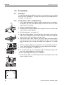
2.3
Installing connection cable
➜ Route the connection cable to the terminal so that it is protected from possible
damage.
Extension of connection cable
▲ An extension of the connection cable is only permitted according to the guide for
installers for the explosion-protected weighing system.
2.3.1
1
KC...x/KCS...x
The connection cable is stored inside the weighing platform during transport for
protection.
1. Route out the connection cable under the base frame.
2
3
2. Remount the load carrier (1) so that the symbol O is located above the level
indicator. Make sure that the load supports (2) in the corners of the weighing
platform are vertical.
3. Fold out the lift-off locks (3) on both faces of the load carrier for lifting.
The lift-off locks are used both to lift off the load carrier (Pos. A) and to prevent
lifting off and tilting (Pos. B) during weighing.
A
3
B
10
Installation information 22006746A 04/04
Installation
Floor scales / Pit scales
2.3.2
2
KD...x/KE...x/KE...skx/KES...x/KES...skx
The connection cable (1) is stored inside the weighing platform during transport for
protection. Depending on the conditions at the installation location, the connection
cable can be routed out as follows:
• Below the weighing platform on the floor:
Ideal with the recessing installation of the weighing platform. In the case of abovefloor installation protective cable bridges can be laid up to under the weighing
platform.
3
1
• Through the base frame:
Remove the rubber grommet (2) from the hole (3) in the base frame and pull
through the connection cable (1). Push the slotted rubber grommet (2) over the
cable and insert it in the hole (3).
1. Lay on the load plate (4) (fold down) and mount it with the screws (5) (quickrelease locks).
5
4
2. Screw the blind screws into the threads.
2.3.3
2
1
KG...x
The connection cable is stored inside the weighing platform during transport for
protection.
1. At the setup location, route out the cable below the weighing platform on the
floor. In the case of above-floor installation, protective cable bridges can be laid
up to just under the weighing platform.
2. Place the load plate (1) on the load frame and fasten with the screws (2).
2.3.4
2
KN...x
The connection cable (1) is stored inside the cabinet during transport for protection.
Depending on the conditions at the setup location, the connection cable can be
routed out as follows:
• Below the weighing platform on the floor:
Ideal if cover strips have been provided as cable bridges. These can then be laid
below the weighing platform.
3
1
6
7
5
4
• Through the base frame:
Remove the rubber grommet (2) from the hole (3) in the base frame and pull the
connection cable (1) through. Push the slotted rubber grommet (2) over the cable
and insert it in the hole (3).
1. Remove the eye bolts and screw on both covering angle sections (4) with the
screws (5).
2. Mount the cover hood (6) and fasten with the screws (7).
Installation information 22006746A 04/04
11
Installation
Floor scales / Pit scales
2.4
Pit installation
2.4.1
Producing pit
The mounting material and detailed instructions for constructing the pit are included
with the pit-frame installation kit. The proper construction of the pit according to these
instructions is a requirement.
2.4.2
Installing the KC...x/KCS...x weighing platform
1. Lay the drawing provided in the pit as a drilling template. Centre the template in
all directions and secure with adhesive tape. Drill the four holes at the points
marked and insert the plugs.
d = 14
2. Measure the pit depth at the corners.
3. Roughly adjust the weighing platform to the height of or flushness with the floor
outside the pit using the foot bolts.
90
4. Lift off the load carrier, see Section 2.2.1.
5. Place the weighing platform in the pit and align. When doing so, also pull the
cable into the empty pipe or cable conduit. For details on routing the empty pipe
to the terminal, see the instructions on pit construction.
1
6. Adjust flushness to the floor. To do this, lay a 6 mm spacer on the load supports
(1) and check with a ruler from the upper edge of the pit frame. Adjust the height
with the foot bolts while ensuring even contact of the support feet, see Section
2.2.1.
7. Mount the weighing platform on the pit floor on the four foot bolts (2) with the
screws (3) and lugs (4). Before tightening, check the distance to the pit edge.
8. Release the transport locks, see Section 2.2.1.
2
4
3
9. Fit the load carrier (5). The swivelled-out lifting and tilting locks (6) on both
faces of the weighing platform serve as lifting aids.
10. Lay the left and right cover strips (7) in the pit frame.
11. Final inspection: Make sure that the distance between the load carrier and the pit
frame is equal on all sides.
5
6
7
12
Installation information 22006746A 04/04
Installation
Floor scales / Pit scales
2.4.3
Installing weighing platform KD...x/KE...x/KE...skx/KES...x/KES...skx
1. Lift off the load plate and route out the connection cable under the weighing
platform, see Section 2.2.2.
2. Slowly lower the weighing platform into the pit by the eye bolts. When doing so,
also pull the cable into the empty pipe or cable conduit.
3. Release the lift-off lock, see Section 2.2.2.
4. Adjust flushness to the floor.
To do this, lay spacers (KD...x/KE...x: 8 mm, KE...skx: 6 mm) on the load frame
at the corners and adjust flush with the upper edge of the pit frame. Adjust the
height of the support feet. To level, see section 2.2.2.
5. Level out, see Section 2.2.2.
2
1
6. Insert the clamping plates (2) provided in the installation kit between the pit wall
and the clamping screw (1) so that they stand up on the pit floor. Centre the
weighing platform in the pit with 6 or 8 clamping screws (1) and clamp firmly in
place. Lock the bolts (1) on the inside of the base frame with the nuts (3).
3
7. Lay on the load plate and screw on firmly.
2.4.4
Installing KG...x weighing platform
1. Measure the pit depth at the corners.
2. Roughly adjust the weighing platform flush with the floor outside the pit using the
foot bolts.
3. Remove the load plate and route out the connection cable under the weighing
platform.
4. Slowly lower the weighing platform into the pit. When doing so, pull the cable
into the empty pipe or cable conduit.
5. Release transport locks.
6. Adjust flushness to the floor.
For this purpose, place 6 mm spacers on the load carrier at the corners, and
check with a ruler from the upper edge of the base frame.
Adjust the height with the foot bolts while ensuring even contact of the support
feet.
7. Level out, see section 2.2.3.
2
8. Insert clamping plates (2) between the pit wall and the clamping bolt (1) so that
they stand up on the pit floor.
1
3
9. Clamp the weighing platform in the pit with eight clamping bolts (1) and centre it
at the same time.
10. Lock the clamping bolts (1) on the inside of the base frame with the nuts (3).
Installation information 22006746A 04/04
13
Configuration possibilities
3
Floor scales / Pit scales
Configuration possibilities
3.1
3.1.1
General information
MultiInterval
• MultiInterval precision means automatic switchover of the numerical increment
(readability) in dependence on the applied load.
3.1.2
• Single Range and High Resolution mean that the numerical increments
(readability) remain the same across the entire weighing range.
Numerical
increment
0 Load weighed
Single Range and High Resolution
max.
3.1.3
Additional setting options
• All other adjustment variables (adjustment to the weighing process and vibrations,
as well as adjustment of stability monitoring and the zero point correction) are
adjusted to the usual user conditions, however can be changed in the master
mode of the weighing terminal if necessary.
• The Identcard provided is labelled with the standard configuration. Mount the
Identcard in accordance with the installation instructions of the weighing terminal
concerned.
• If the standard configuration does not meet your needs, it is possible to reconfigure
the weighing platform with the terminal. To do this, see the terminal operating
instructions or the Service Manual for the TBrick Service Mode.
• A set of measuring data signs is provided with the weighing platform. Apply the
selected configuration corresponding to the factory-mounted measuring data sign
to the Identcard, and the Max-Min sign near the terminal display.
• When the configuration is changed, it is also possible to change the preload range
in addition to the weighing range and the readability.
14
Installation information 22006746A 04/04
Configuration possibilities
Floor scales / Pit scales
3.2
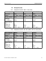
3.2.1
Configuration data
Configuration data for KC...x/KCS...x, factory setting
Standard configuration
KC300..x
KCS300..x
KC600..x/KCS600..x
Maximum load
300 kg
300 kg
600 kg
Readability
0 ... 300 kg
Tare range, subtractive
300 kg
300 kg
600 kg
Preload range
Zero-set range
Zero-set range (typ.)
± 6 kg
105 kg
± 6 kg
120 kg
± 12 kg
255 kg
Calibration data as per
OIML
Calibration class
Calibration value
Minimum load
Temperature range
III
0.05 kg
1.0 kg
–10 °C ... +40 °C
III
0.05 kg
1.0 kg
–10 °C ... +40 °C
II
0.1 kg
0.5 kg
0 °C ... +40 °C
3.2.2
0.002 kg
0 ... 300 kg
0.002 kg
0 ... 600 kg
0.01 kg
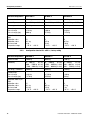
Configuration data for KD...x/KE...x/KE...skx/KES...x/KES...skx, factory setting
Standard configuration
KD600..x
KD1500..x
KE1500..x
Maximum load
600 kg
1500 kg
1500 kg
Readability
0 ... 600 kg
Tare range, subtractive
600 kg
1500 kg
1500 kg
Preload range
Zero-set range
Zero-set range (typ.)
± 12 kg
200 kg
± 30 kg
640 kg
± 30 kg
600 kg
Calibration data as per
OIML
Calibration class
Calibration value
Minimum load
Temperature range
III
0.1 kg
2 kg
–10 °C ... +40 °C
III
0.2 kg
4 kg
–10 °C ... +40 °C
III
0.2 kg
4 kg
–10 °C ... +40 °C
Installation information 22006746A 04/04
0.01 kg
0 ... 1500 kg
0.02 kg
0 ... 1500 kg
0.02 kg
15
Configuration possibilities
Floor scales / Pit scales
Standard configuration
KES1500..x
KE3000..x
KES3000..x
Maximum load
1500 kg
3000 kg
3000 kg
Readability
0 ... 1500 kg
Tare range, subtractive
1500 kg
3000 kg
3000 kg
Preload range
Zero-set range
Zero-set range (typ.)
± 30 kg
600 kg
± 60 kg
1270 kg
± 60 kg
1270 kg
Calibration data as per
OIML
Calibration class
Calibration value
Minimum load
Temperature range
III
0.2 kg
4 kg
–10 °C ... +40 °C
III
0.5 kg
10 kg
–10 °C ... +40 °C
III
0.5 kg
10 kg
–10 °C ... +40 °C
3.2.3
0.02 kg
0 ... 3000 kg
0.05 kg
0 ... 3000 kg
0.05 kg
Configuration data for KG...x/KN...x, factory setting
Standard configuration
KG3000..x
KG6000..x
KN1500..x
Maximum load
3000 kg
6000 kg
1500 kg
Readability
0 ... 600 kg
0.2 kg
600 ... 1500 kg 0.5 kg
1500 ...3000 kg 1.0 kg
0 ... 1500 kg
0.5 kg
1500 ... 3000 kg 1.0 kg
3000 ... 6000 kg 2.0 kg
0 ... 300 kg
0.1 kg
300 ... 600 kg 0.2 kg
600 ... 1500 kg 0.5 kg
Tare range, subtractive
3000 kg
6000 kg
1500 kg
Preload range
Zero-set range
Zero-set range (typ.)
± 60 kg
1270 kg
± 120 kg
2550 kg
± 30 kg
630 kg
Calibration data as per
OIML
Calibration class
Calibration value
Minimum load
Temperature range
III
0.2 kg
4.0 kg
–10 °C ... +40 °C
III
0.5 kg
10 kg
–10 °C ... +40 °C
III
0.1 kg
2 kg
–10 °C ... +40 °C
16
Installation information 22006746A 04/04
Planning assemblies
Floor scales / Pit scales
4
Planning assemblies
4.1
Notes on planning
Due to their design characteristics, the weighing platforms are suitable for installation
in conveying systems. The following specifications and dimensional drawings form
the basis for the design of the required assemblies.
• The weighing platform may only be supported by the support feet, and never by
the frame or lever parts.
• The weighing platform may only be permanently installed on the support feet.
• Moving or rotating parts on the weighing platform must be designed so that they
do not affect the weighing result. Balance rotating parts.
• The load plate must be free on all sides so that not connection between the load
plate and permanently mounted parts is made, even by falling parts or dirt
deposits.
• Lay cables or hoses between the weighing platform and other machine parts so
that they do not exert any force on the weighing platform.
EXPLOSION RISK
The assemblies are also part of the explosion-protected weighing system.
➜ Use only assemblies which are suitable for the application in hazardous areas.
➜ Make sure that there is no increased risk due to electrostatic charge of the
assemblies.
CAUTION
When mounting assemblies, make sure that no metal chips get into the weighing
platform.
➜ Remove the load plate to machine the weighing platform.
Installation information 22006746A 04/04
17
Planning assemblies
Floor scales / Pit scales
4.2
Preload range
The weight of the structural parts permanently mounted on the weighing platform is
referred to as "preload". The preload is electrically compensated in the weighing
platform so that the full weighing range is available.
The maximum preload (or the zero-set range) that can be compensated is dependent
on the configured weighing range.
CAUTION
The assemblies must already be mounted when connecting the weighing platform.
Model
18
Weighing range
Max. preload
KC300..x
300 kg
105 kg
KCS300..x
300 kg
120 kg
KC600..x
600 kg
255 kg
KCS600..x
600 kg
255 kg
KD600..x
600 kg
200 kg
KD1500..x
1500 kg
640 kg
KE1500..x
1500 kg
600 kg
KES1500..x
1500 kg
600 kg
KE3000..x
3000 kg
1270 kg
KES3000..x
3000 kg
1270 kg
KG3000..x
3000 kg
1270 kg
KG6000..x
6000 kg
2550 kg
KN1500..x
1500 kg
630 kg
Installation information 22006746A 04/04
Planning assemblies
Floor scales / Pit scales
4.3
4.3.1
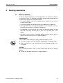
Mounting possibilities
Mounting possibilities for KC...x
800
787
800
662
630
487
420
310
289
230
160
139
13 0
0
0 44 127.5
237.5
390
610
762.5
872.5 956
24
1000
976
Dim. in mm
• Bridge assemblies can be mounted in the shaded or hatched areas.
max. 10 mm
• Recommended mounting type: Bolting on.
Remove the load plate and drill through for this purpose.
• Mounting parts (e.g. bolts and nuts) may extend a maximum of 10 mm beyond
the underside of the load plate.
Only for KC300..x
Only for KC600..x
For KC300..x and KC600..x
Technical version: 08/2000
Installation information 22006746A 04/04
19
Planning assemblies
Floor scales / Pit scales
4.3.2
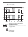
Mounting possibilities for KCS...x
800
787
800
662
630
487
420
310
289
230
160
139
13 0
0
0 44
250
380
561
24
671
756
800
Dim. in mm
776
• Bridge assemblies can be mounted in the shaded areas.
max. 10 mm
• Recommended mounting type: Bolting on.
Remove the load plate and drill through for this purpose.
• Mounting parts (e.g. bolts and nuts) may extend a maximum of 10 mm beyond
the underside of the load plate.
Only for KCS300..x
Only for KCS600..x
For KCS300..x and KCS600..x
Technical version: 08/2000
20
Installation information 22006746A 04/04
Planning assemblies
Floor scales / Pit scales
4.3.3
25
0 55
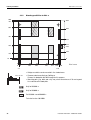
Mounting possibilities for KD...x
418
388
300
675
862
832
950
1225
1195
1000
975
945
870
915
470
380
55
25
85
130
0
0
0
160
340
436 536 714 814
910
1090 1250
Dim. in mm
• Bridge assemblies can be mounted in the shaded areas.
max. 10 mm
• Recommended mounting type: Bolting on.
Remove the load plate and drill through for this purpose.
• Mounting parts (e.g. bolts and nuts) may extend a maximum of 10 mm beyond
the underside of the load plate or load frame.
Mounting possibilities on the load plate
Mounting possibilities on the load frame
Technical version: 08/2000
Installation information 22006746A 04/04
21
Planning assemblies
Floor scales / Pit scales
4.3.4
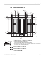
Mounting possibilities for KE...x
966
350
25
0 55
442
466
510
990
1034
1058
534
1150
1445
1475
1500
1225
1195
1165
1250
1120
620
480
85
55
25
130
0
0
0
160
410
550 650 850 950 1090
700
1340 1500
Dim. in mm
• Bridge assemblies can be mounted in the shaded areas.
max. 10 mm
• Recommended mounting type: Bolting on.
Remove the load plate and drill through for this purpose.
• Mounting parts (e.g. bolts and nuts) may extend a maximum of 10 mm beyond
the underside of the load plate or load frame.
Mounting possibilities on the load plate
Mounting possibilities on the load frame
Technical version: 08/2000
22
Installation information 22006746A 04/04
Planning assemblies
Floor scales / Pit scales
4.3.5
Mounting possibilities for KE...skx
350
25
0 55
966
432
456
510
534
990
1044
1068
1150
1475
1445 1500
1250
1225
1195
1165
1250
1125
620
480
85
55
25
130
0
0
0
160
290
550 650
850 950
1210
1340
1500
Dim. in mm
700
• Bridge assemblies can be mounted in the shaded areas.
max. 10 mm
• Recommended mounting type: Bolting on.
Remove the load plate and drill through for this purpose.
• Mounting parts (e.g. bolts and nuts) may extend a maximum of 10 mm beyond
the underside of the load plate or load frame.
Mounting possibilities on the load plate
Mounting possibilities on the load frame
Technical version: 08/2000
Installation information 22006746A 04/04
23
Planning assemblies
Floor scales / Pit scales
4.3.6
Mounting possibilities for KES...x/KES...skx
963
350
439
466
510
537
650
25
0 55
990
1034
1061
1475
1150
850
1445
1500
1475
1445
1415
1500
1370
770
630
85
55
25
130
0
0
0
160
290
550
700
950
1090
1340 1500
Dim. in mm
• Bridge assemblies can be mounted in the shaded areas.
max. 10 mm
• Recommended mounting type: Bolting on.
Remove the load plate and drill through for this purpose.
• Mounting parts (e.g. bolts and nuts) may extend a maximum of 10 mm beyond
the underside of the load plate or load frame.
Mounting possibilities on the load plate
Mounting possibilities on the load frame
Technical version: 08/2000
24
Installation information 22006746A 04/04
Planning assemblies
Floor scales / Pit scales
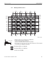
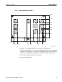
4.3.7
Mounting possibilities for KG...x
1656
1900
1546
1290
1180
820
454
710
100
344
0
1500
1399
1409
1321
1311
1221
1211
977
967
877
867
633
623
533
523
289
279
189
179
101
0
91
0
1910
2000
1556
1646
1190 1055
1280
720
810
354
444
0
90
Dim. in mm
• Bridge assemblies can be mounted in the shaded areas.
max. 10 mm
• Recommended mounting type: Bolting on.
Remove the load plate and drill through for this purpose.
• Mounting parts (e.g. bolts and nuts) may extend a maximum of 10 mm beyond
the underside of the load plate or load frame.
Mounting possibilities on the load plate
Mounting possibilities on the load frame
Technical version: 08/2000
Installation information 22006746A 04/04
25
Planning assemblies
Floor scales / Pit scales
4.4
4.4.1
Opening possibilities
Opening possibilities for KC...x
800
661.5
KC600..x
471.5
288.5
KC300..x
KC600..x
230
138.5
0
0
405
595
1000
Dim. in mm
• Openings, e.g. for emptying tank, can be made in the shaded areas.
• The measuring cell TBrick ..-Ex has an individual terminal box which is mounted
nearby the measuring cell. If required, the terminal box can be removed and
reinstalled in a suitable place.
• Remove the load plate to produce the opening.
Technical version: 08/2000
26
Installation information 22006746A 04/04
Planning assemblies
Floor scales / Pit scales
4.4.2
Opening possibilities for KCS...x
800
661.5
KCS600..x
471.5
288.5
KCS300..x
KCS600..x
230
138.5
0
0
240
420
800
Dim. in mm
• Openings, e.g. for emptying tank, can be made in the shaded areas.
• The measuring cell TBrick ..-Ex has an individual terminal box which is mounted
nearby the measuring cell. If required, the terminal box can be removed and
reinstalled in a suitable place.
• Remove the load plate to produce the opening.
Technical version: 08/2000
Installation information 22006746A 04/04
27
Planning assemblies
Floor scales / Pit scales
4.4.3
Opening possibilities for KD...x
1000
860
610
550
130
0
0
180
370 475 575
415
775
880 1070
835
1250
Dim. in mm
• Openings, e.g. for emptying tank, can be made in the shaded areas.
• The measuring cell TBrick ..-Ex has an individual terminal box which is mounted
nearby the measuring cell. If required, the terminal box can be removed and
reinstalled in a suitable place.
• Remove the load plate to produce the opening.
Technical version: 08/2000
28
Installation information 22006746A 04/04
Planning assemblies
Floor scales / Pit scales
4.4.4
Opening possibilities for KE...x/KE...skx
1250
1120
740
680
130
0
0
180
270
700
1230 1320
1500
Dim. in mm
• Openings, e.g. for emptying tank, can be made in the shaded areas.
• The measuring cell TBrick ..-Ex has an individual terminal box which is mounted
nearby the measuring cell. If required, the terminal box can be removed and
reinstalled in a suitable place.
• Remove the load plate to produce the opening.
Technical version: 08/2000
Installation information 22006746A 04/04
29
Planning assemblies
Floor scales / Pit scales
4.4.5
Opening possibilities for KES...x/KES...skx
1500
1370
740
680
130
0
0
180
425
700
1075
1320
1500
Dim. in mm
• Openings, e.g. for emptying tank, can be made in the shaded areas.
• The measuring cell TBrick ..-Ex has an individual terminal box which is mounted
nearby the measuring cell. If required, the terminal box can be removed and
reinstalled in a suitable place.
• Remove the load plate to produce the opening.
Technical version: 08/2000
30
Installation information 22006746A 04/04
Planning assemblies
Floor scales / Pit scales
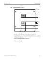
4.4.6
Opening possibilities for KG...x
1500
1210
980
864
634
520
290
0
2000
1850
1880
1090
1650
1055 860
690
350
460
120 0
150
Dim. in mm
• Openings, e.g. for emptying tank, can be made in the shaded areas.
• The measuring cell TBrick ..-Ex has an individual terminal box which is mounted
nearby the measuring cell. If required, the terminal box can be removed and
reinstalled in a suitable place. Remove the load plate to produce the opening.
• Remove the load plate to produce the opening.
Technical version: 08/2000
Installation information 22006746A 04/04
31
Dimensions
5
Floor scales / Pit scales
Dimensions
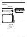
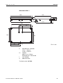
Dimensions of KC...x
1000
800
4
100
890
18
972
32 FS
H
D
86
380
30
778
610
C1
C2
235
625
L
230
Dim. in mm
932
H
FS
L
C1
C2
Adjustable with 4 foot bolts
Min. H = 115 mm
Max. H = 140 mm
Foot bolt
Spanner size = 19 mm
Required area D = 40 mm dia.
Level indicator
Cable connection of KC300..x
Cable connection of KC600..x
Technical version: 08/2000
32
Installation information 22006746A 04/04
Dimensions
Floor scales / Pit scales
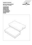
Dimensions of KCS...x
800
800
4
100
692
18
772
32 FS
H
86
D
30
380
778
507
C1
230
C2
625
L
230
Dim. in mm
732
H
FS
L
C1
C2
Adjustable with 4 foot bolts
Min. H = 115 mm
Max. H = 140 mm
Foot bolt
Spanner size = 19 mm
Required area D = 40 mm dia.
Level indicator
Cable connection of KCS300..x
Cable connection of KCS600..x
Technical version: 08/2000
Installation information 22006746A 04/04
33
Dimensions
Floor scales / Pit scales
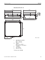
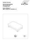
Dimensions of KD...x
1250
1000
575
G
60
L
710
240
1190
166
H
30
FS
20
D
940
1230
32
980
1110
890
455
L
C
H
FS
G
L
C
Dim. in mm
Adjustable with 4 foot bolts
Min. H = 180 mm
Max. H = 205 mm
Foot bolt
Spanner size = 30 mm
Required area D = 60 x 60 mm
Thread M12
Level indicator
Cable connection
Technical version: 08/2000
34
Installation information 22006746A 04/04
Dimensions
Floor scales / Pit scales
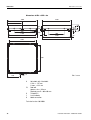
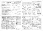
Dimensions of KE...x/KE...skx
1500
1250
700
G
60
L
960
240
1440
168
H
30
FS
20
D
1190
1480
32
1230
1360
1140
580
L
C
H
FS
G
L
C
Dim. in mm
Adjustable with 4 foot bolts
Min. H = 182 mm
Max. H = 207 mm
Foot bolt
Spanner size = 30 mm
Required area D = 60 x 60 mm
Thread M12
Level indicator
Cable connection
Technical version: 08/2000
Installation information 22006746A 04/04
35
Dimensions
Floor scales / Pit scales
Dimensions of KES...x/KES...skx
1500
1500
700
G
183
H
75
30
L
960
240
1440
FS
960
D
1480
1440
20
32
1480
1360
1390
580
C
L
H
FS
G
L
C
Dim. in mm
Adjustable with 4 foot bolts
H min. = 197 mm
H max. = 222 mm
Foot bolt
Spanner size = 30 mm
Required area D = 60 x 60 mm
Thread M12
Level indicator
Cable connection
Technical version: 08/2000
36
Installation information 22006746A 04/04
Dimensions
Floor scales / Pit scales
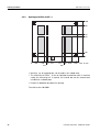
Dimensions of KG...x
2000
1500
175
55 H
20
D
1965
1470
FS
24
1880
330
915
1380
810
825 C
945
L
H
FS
L
C
Dim. in mm
Adjustable with 4 foot bolts
H min. = 196 mm
H max. = 246 mm
Foot bolt
Spanner size = 30 mm
Required area D = 90 mm dia.
Level indicator
Cable connection
Technical version: 08/2000
Installation information 22006746A 04/04
37
Dimensions
Floor scales / Pit scales
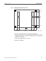
Dimensions of KN...x
1500
600
200
660
245 150
15
H
1880
FS
D
1125
L
825
22
C
1380
1250 1995
410
1655
1790
1905
H
FS
L
C
Dim. in mm
Adjustable with 4 foot bolts
H min. = 55 mm
H max. = 100 mm
Foot bolt
Spanner size = 36 mm
Required area D = 90 mm dia.
Level indicator
Cable connection
Technical version: 08/2000
38
Installation information 22006746A 04/04
22006746A
Subject to technical changes
© Mettler-Toledo (Albstadt) GmbH 04/04
Mettler-Toledo (Albstadt) GmbH
D-72458 Albstadt
Tel. ++49-7431-14 0, Fax ++49-7431-14 232
Internet: http://www.mt.com
Printed in Germany 22006746A