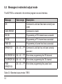
1
WZ FSE 2-2
Quick reference guide
Radio unit for voice and data transmission in the 2 m band
Safety precautions
Please note!
•
The units are not suitable for operation in rooms with an explosive atmosphere as well as damp environments or in rooms with aggressive air or
increased electromagnetic requirements.
•
Mind the instructions for putting into operation.
•
Both the casing and the antenna may become very hot (you may get burned)
during sending operation. Provide for sufficient cooling and air circulation.
•
Installation of the antenna needs to be in accordance with the valid regulations and requirements for protection of human beings within electromagnetic fields.
•
Avoid to touch conductive parts of the device.
•
Do not open the device yourself, only permit repairs by the manufacturer.
2
ESD protection measures
Comply with the ESD protection measures according to
DIN EN 61340-5-1/2 when opening the unit (potential equalisation
between body and ground of the unit via high-value resistance
(approx. 1 MOhm) e. g. with a usual wrist band.).
Information regarding the used trademarks
Microsoft® and Windows® are registered trademarks of the Microsoft Corporation. All the other trademarks and product names are trademarks or registered
trademarks of the relevant company.
Copyright
All rights reserved.
Duplication of these instructions for use or parts thereof by any reproduction method whatsoever is not permitted without prior permission of the manufacturer.
Amendments may be published without prior notification.
Notwithstanding the above declaration, the manufacturer accepts no liability for errors in these
instructions or their consequences.
3
Safety precautions
Read the user manual carefully to be able to use the wealth of features of your
new WZ FSE 2-2. You can find further information about this topic on our website
http://www.fmncom.com.
1. General instructions
•
In order to be allowed to operate the radio unit you must apply for a license
at your local authorities and they will assign you a frequency.
•
All connection cables have to be equipped with an earth-connected shielding.
The connection cable for the antenna has to be equipped with a wave impedance of 50 Ω.
•
The manufacturer recommends to mount devices in printed circuit board
version into a metal housing.
•
Corresponding mechanisms are to be used for the detection of single bit errors during a data transmission (e.g. protocol with creation of check sum).
•
Only use antenna designated for the frequency range. Failure to observe this
instruction will cause the approval to expire and may result in legal action.
•
The connected antenna has to be tuned to the working frequency of the radio set to get a maximum range.
•
The use of an antenna that has not been tuned can lead to destruction of the
radion unit!
•
Provide sufficinet cooling! (e.g. a heat energy of about 30 W has to be eliminated in case of a transmitting power of 6 W.)
4
Further troubleshooting can be necessary in case of operation e. g. at
switching power supplies.
•
The compliance with the instructions for use and for putting into operation
also belongs to the intended use. Every other use is considered to be not
intended. The manufacturer accepts no liability for any damages resulting
from such other use.
5
General instructions
•
2. General product description
2.1 Designation of the function elements
Antenna
Pin20
Pin1
Pin4
User interface
Pin1
Power supply
Figure 2-1: Designation of the function elements
6
2.2 Interfaces of the radio unit
2.2.1
Pin assignment of the power supply
The pins are assigned as follows:
Pin designation
at the socket
1
Voltage supply 10.8 ... 15.6 V DC
2
Ground
3
Ground
4
Voltage supply 10.8 ... 15.6 V DC
Product description
Assignment
Table 2-1: Pin assignment of the power supply
7
2.2.2
Pin
8
Pin assignment of the user interface for analogue peripherals
Assignment
Function
1
STAST
Input, digital
2
RSSI
Output, digital
3
MOD+
Input, analogue
4
MOD-
Input, analogue
5
NF+
Output, analogue
6
NF-
Output, analogue
7
RS232_IN
Input, digital
8
AUDIO
DATA
Input, digital,
9
DATA_IN
Input, analogue
10
GND
Input, digital
11
DATA_OUT
Output, analogue
Assignment
Function
12
SEL0
Input, digital
13
SEL1
Input, digital,
14
SEL2
Input, digital
15
SEL3
Input, digital
16
SEL4
Input, digital
17
+5V_OUT
Output
18
UET
Output, digital
19
RS232_OUT
Output, digital
20
ERROR
Output, digital
Product description
Pin
9
2.2.3
Pin assignment of the user interface for digital peripherals
(FFSK or GMSK modem)
Pin
10
Assignment
Function
1
RTS
Input, digital, RS232
2
RSSI
Output, analogue
3
RXD
Output, digital
4
DCD
Output, digital
5
TXD
Input, digital
6
GND
Ground
7
RS232_IN
Input, digital
8
TXC
Output, digital
9
BAUD0
Input, digital
10
GND
Ground
11
BAUD1
Input, digital
Assignment
Function
12
SEL0
Input, digital
13
SEL1
Input, digital
14
SEL2
Input, digital
15
SEL3
Input, digital
16
SEL4
Input, digital
17
RXC
Output, digital
18
UET
Output, digital
19
RS232_OUT
Output, digital
20
ERROR
Output, digital
Product description
Pin
11
3. Putting into operation
3.1 Basic mode when the unit has been switched on
see manual WZ FSE 2-2
3.2 Memory selection at the user interface
see manual WZ FSE 2-2
12
4. Settings
Commands
Value range
V
Description
See
chapter
in user
manual
Output of the software version
5.1.1
N
ASCII 16 digits
Output of the serial number of the unit
5.1.2
EX
X = 0 ... 1
Echo of the commands
(X = 0 -> no echo, X = 1 -> echo)
5.1.3
?EX
X = 0 ... 1
Output mode (X = 0 -> normal,
X = 1 -> extended) (service command)
5.1.4
Output of all the information about the
32 memories (T, R, P)
5.1.5
Output of the information about a single
memory (T, R, P)
5.1.5
M
MX
X = 0 ... 31
13
Puuting into operation / Settings
4.1 Software commands
Commands
Value range
Description
See
chapter
in user
manual
SMX
X = 0 ... 31
Software selection: selection of the
memory and the relevant TX/ RX
channels and the power level
5.1.6
KX
X = 0 ... 31
Setting the number of the memory
(for TX, RX and PX command)
5.1.7
TX
X = 0 ... 2518
Programming a new transmit channel
(on the selected memory -> KX)
5.1.7
RX
X = 0 ... 2518
Programming a new receive channel
(on the selected memory -> KX)
5.1.7
PX
X = 1 ... 5
Programming a new power level
(on the selected memory -> KX)
5.1.7
?T
Output of the current TX channel
number (service command)
5.1.8
?R
Output of the current RX channel
number (service command)
5.1.9
14
Value range
Description
See
chapter
in user
manual
?P
Output of the current power level
(service command)
5.1.10
?SM
Output of the number of the current
memory (service command)
5.1.11
SM
Hardware selection: selection of the
memory and the relevant TX/ RX channels and the power level depending on
the hardware setting (connection of the
inputs SEL0 ... SEL4 (pins 12 ... 16))
5.1.12
A0
Output of the analogue RSSI signal
(input level)
5.1.13
Xon/Xoff - protocol: X = 0 -> switch off,
X = 1 -> switch on
5.1.14
Restoring the factory preset
5.1.15
XX
F
X = 0 ... 1
Settings
Commands
Tabelle 4-1: Overview of the commands
15
4.2 Calculating the channels and frequencies
Channel =
Frequency [MHz] - Start frequency [MHz]
+ Channel offset
Channel spacing [MHz]
Frequency [MHz] = Start frequency [MHz] + (Channel - Channel offset)* Channel spacing [MHz]
Equation 4-1: General formulas for calculation of the channels and frequencies
Channel
range
Channel
spacing
Start
frequency
Stop
frequency
Channel
offset
WZ FSE 2-2
0000 ... 1399
0.0200 MHz
146.0100 MHz
173.9900 MHz
0
1400 ... 2518
0.0250 MHz
146.0250 MHz
173.9750 MHz
1400
137.0000 MHz
160.0000 MHz
160
165.0000 MHz
195.0000 MHz
0
WZ FSE 2-2 (HK)
0160 ... 2000
0.0125 MHz
WZ FSE 2-2 (UK)
0000 ... 2400
0.0125 MHz
Table 4-2: Overview of the specific parameters of the relevant unit for calculating
16
5. Troubleshooting
Troubleshooting
5.1 Messages in normal output mode
The WZ FSE is connected to the terminal program via serial interface.
Error message
Description
OK
Command is valid and has been executed correctly
ERROR
Command is valid but could not be executed correctly
CMD-ERROR
Command is invalid
Table 5-1: Normal output mode (“?E0“)
17
5.2 Messages in extended output mode
The WZ FSE is connected to the terminal program via serial interface.
Message
Value range
Description
OK
Command is valid and has been correctly executed
CMD-ERROR
Command is invalid
RX OK
Programming of RX channel was successful
TX OK
Programming of TX channel was successful
PWR OK
Programming of power level was successful
ERROR XX
XX = 00 ... FF
Command is valid but has not been correctly
executed
RX ERROR XX
XX = 00 ... FF
Error when programming the RX channel
TX ERROR XX
XX = 00 ... FF
Error when programming the TX channel
PWR
ERROR XX
XX = 00 ... FF
Error when programming the power level
Table 5-2: Extended output mode (“?E1“)
18
6. Conformity
The FMN communications GmbH declares that the radio unit WZ FSE 2-2 complies
with the basic requirements and the other relevant provisions of the directive
1999/5/EG (R&TTE directive).
The WZ FSE 2-2 can be operated in the countries of the European Union (EU). Outside of the EU apply the national regulations of the relevant country.
Conformity
The complete declaration of conformity can be found and downloaded on our website
http://www.fmncom.com.
19
For the sake of the environment!
Waste paper content of 100 %.
FMN communications GmbH
Grimmelallee 4
99734 Nordhausen, Germany
P.O.Box 10 04 65
99724 Nordhausen, Germany
Phone:
Fax:
Email
Internet
+49 (36 31) 56-34 41
+49 (36 31) 56-32 24
[email protected]
www.fmncom.com
Subject to change.
WZ FSE 2-2: Ka8402.0024.320.001
Edition: No. 10/06 (1112-0757)