1
48-Port ADSL 2/2+ IP DSLAM
IDL-4802 / IDL-4802-48
User's Manual
-1-
Copyright
Copyright (C) 2009 PLANET Technology Corp. All rights reserved.
The products and programs described in this User’s Manual are licensed products of PLANET
Technology, This User’s Manual contains proprietary information protected by copyright, and this
User’s Manual and all accompanying hardware, software, and documentation are copyrighted.
No part of this User’s Manual may be copied, photocopied, reproduced, translated, or reduced to
any electronic medium or machine-readable form by any means by electronic or mechanical.
Including photocopying, recording, or information storage and retrieval systems, for any purpose
other than the purchaser's personal use, and without the prior express written permission of
PLANET Technology.
Disclaimer
PLANET Technology does not warrant that the hardware will work properly in all environments and
applications, and makes no warranty and representation, either implied or expressed, with respect
to the quality, performance, merchantability, or fitness for a particular purpose.
PLANET has made every effort to ensure that this User’s Manual is accurate; PLANET disclaims
liability for any inaccuracies or omissions that may have occurred.
Information in this User’s Manual is subject to change without notice and does not represent a
commitment on the part of PLANET. PLANET assumes no responsibility for any inaccuracies that
may be contained in this User’s Manual. PLANET makes no commitment to update or keep current
the information in this User’s Manual, and reserves the right to make improvements to this User’s
Manual and/or to the products described in this User’s Manual, at any time without notice.
If you find information in this manual that is incorrect, misleading, or incomplete, we would
appreciate your comments and suggestions.
FCC Warning
This equipment has been tested and found to comply with the limits for a Class A digital device,
pursuant to Part 15 of the FCC Rules. These limits are designed to provide reasonable protection
against harmful interference when the equipment is operated in a commercial environment. This
equipment generates, uses, and can radiate radio frequency energy and, if not installed and used in
accordance with the Instruction manual, may cause harmful interference to radio communications.
Operation of this equipment in a residential area is likely to cause harmful interference in which
case the user will be required to correct the interference at his own expense.
FCC Caution
To assure continued compliance (example-use only shielded interface cables when connecting to
computer or peripheral devices). Any changes or modifications not expressly approved by the party
responsible for compliance could void the user’s authority to operate the equipment.
This device complies with Part 15 of the FCC Rules. Operation is subject to the Following two
conditions: (1) This device may not cause harmful interference, and (2) this Device must accept any
interference received, including interference that may cause undesired operation.
CE mark Warning
The is a class A device, In a domestic environment, this product may cause radio interference, in
which case the user may be required to take adequate measures.
Trademarks
The PLANET logo is a trademark of PLANET Technology. This documentation may refer to
numerous hardware and software products by their trade names. In most, if not all cases, these
designations are claimed as trademarks or registered trademarks by their respective companies.
-2-
WEEE Warning
To avoid the potential effects on the environment and human health as a result of
the presence of hazardous substances in electrical and electronic equipment, end
users of electrical and electronic equipment should understand the meaning of the
crossed-out wheeled bin symbol. Do not dispose of WEEE as unsorted municipal
waste and have to collect such WEEE separately.
Safety
This equipment is designed with the utmost care for the safety of those who install and use it.
However, special attention must be paid to the dangers of electric shock and static electricity when
working with electrical equipment. All guidelines of this and of the computer manufacture must
therefore be allowed at all times to ensure the safe use of the equipment.
Revision
User’s Manual for PLANET 48-Port ADSL 2/2+ IP DSLAM
Model: IDL-4802 / IDL-4802-48
Rev: 1.0 (Mar. 2009)
Part No.: EM-IDL4802_v1
-3-
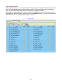
Table of Contents
Introduction .................................................................................................................. 15
1.1 Product Features ................................................................................................... 15
1.2 Package Contents .................................................................................................. 16
1.3 Application ............................................................................................................. 17
1.4 Outlook ................................................................................................................... 18
1.4.1 Front Panel ............................................................................................. 18
1.4.2 Rear Panel.............................................................................................. 19
1.5 Technical Specifications ....................................................................................... 20
Installation .................................................................................................................... 22
2.1 Safety Instruction................................................................................................... 22
2.2 Hardware Installation ............................................................................................. 23
2.2.1 System Requirements ............................................................................ 23
2.2.2 Installation Procedure ............................................................................. 24
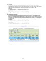
2.3 WEB Configuration ................................................................................................ 34
2.3.1 System Prepartion .................................................................................. 34
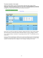
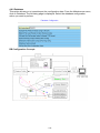
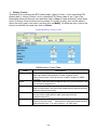
2.3.2 WEB Configuration Procedure................................................................ 35
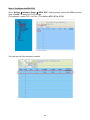
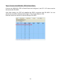
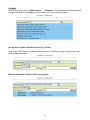
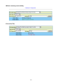
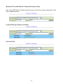
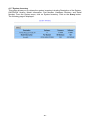
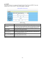
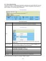
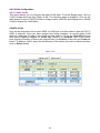
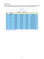
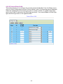
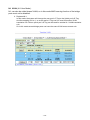
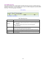
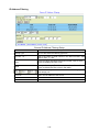
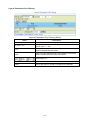
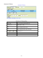
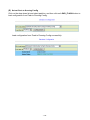
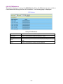
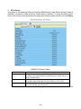
2.3.3 How to backup / Restore the Configuration ............................................ 40
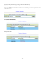
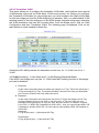
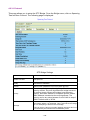
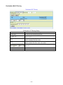
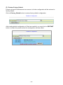
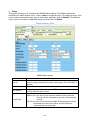
2.3.4 Firmware Update .................................................................................... 50
Software Introduction .................................................................................................. 53
3.1 General Overview................................................................................................... 53
3.1.1 Features of Management Interface......................................................... 54
3.2 Configuration Management .................................................................................. 55
3.2.1 Bridge Configuration ............................................................................... 55
3.2.2 ADSL Configuration ................................................................................ 56
3.3 Performance management .................................................................................... 57
3.3.1 RMON Feature ....................................................................................... 59
3.4 Fault Management ................................................................................................. 60
3.5 Loopback Testing .................................................................................................. 62
3.6 Cluster Feature....................................................................................................... 63
WEB Management........................................................................................................ 64
4.1 System .................................................................................................................... 70
4.1.1 System Information ................................................................................. 70
4.1.2 Board IP Setup ....................................................................................... 71
4.1.3 Ethernet Port Service ............................................................................. 72
4.1.4 ADSL Port Service .................................................................................. 73
4.1.5 CLI Setup................................................................................................ 75
4.1.6 Cluster Setup .......................................................................................... 76
4.1.7 System Inventory .................................................................................... 80
4.1.8 System Contact Info ............................................................................... 81
4.1.9 SNTP ...................................................................................................... 82
4.1.10 IP Routes .............................................................................................. 83
4.1.11 User Administration ............................................................................... 84
4.1.12 Duplicator ............................................................................................. 86
4.2 Bridge ..................................................................................................................... 87
4.2.1 Interface Setup ....................................................................................... 87
4.2.2 VLAN Configuration ................................................................................ 96
4.2.3 Spanning Tree ...................................................................................... 104
4.2.4 Access Control...................................................................................... 108
4.2.5 Forwarding............................................................................................ 134
4.2.6 Relay .................................................................................................... 136
4.2.7 IGMP .................................................................................................... 138
-4-
4.2.8 IPOA ..................................................................................................... 145
4.3 ADSL ..................................................................................................................... 147
4.3.1 Profile ................................................................................................... 147
4.3.2 Data & Inventory ................................................................................... 155
4.3.3 Line Config & Info ..............................................................................162
4.4 Traffic .................................................................................................................... 164
4.4.1 ATM Traffic Descriptor .......................................................................... 164
4.5 SNMP .................................................................................................................... 166
4.5.1 SNMP Community ................................................................................ 166
4.5.2 SNMP Target ........................................................................................ 167
4.5.3 SNMP Notify ......................................................................................... 168
4.6 Maintenance ......................................................................................................... 169
4.6.1 SYS Log Server .................................................................................... 169
4.6.2 Database .............................................................................................. 170
4.6.3 Firmware Update .................................................................................. 178
4.6.4 ATM Loopbacks .................................................................................... 181
4.6.5 Fault Management ................................................................................ 182
4.6.6 Performance Monitoring ....................................................................... 187
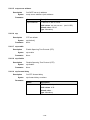
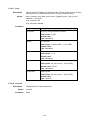
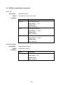
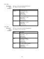
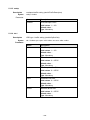
CLI Command Reference .......................................................................................... 204
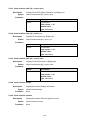
5.1
Global Commands ....................................................................................... 209
5.1.1
bye ........................................................................................... 209
5.1.2
cluster ...................................................................................... 209
5.1.3
cluster local .............................................................................. 209
5.1.4
disable...................................................................................... 209
5.1.5
end ........................................................................................... 209
5.1.6
exit ........................................................................................... 209
5.1.7
help .......................................................................................... 210
5.1.8
list............................................................................................. 210
5.1.9
list opmode ............................................................................... 210
5.1.10
system contact ......................................................................... 210
5.1.11
system location ........................................................................ 210
5.1.12
system name ............................................................................ 211
5.1.13
system restart........................................................................... 211
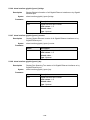
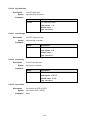
5.2
Initialize Mode Commands.......................................................................... 212
5.2.1
enable ...................................................................................... 212
5.2.2
show license ............................................................................ 212
5.2.3
show time ................................................................................. 212
5.2.4
show uptime ............................................................................. 212
5.2.5
show version ............................................................................ 212
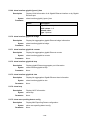
5.3
Enable Mode Commands ............................................................................ 213
5.3.1
configure .................................................................................. 213
5.3.2
ping .......................................................................................... 213
5.3.3
show access-list bcrate ............................................................ 213
5.3.4
show access-list dstip .............................................................. 213
5.3.5
show access-list dstmac .......................................................... 214
5.3.6
show access-list ethertype ....................................................... 214
5.3.7
show access-list ip-allowed ...................................................... 214
5.3.8
show access-list ipprotocol ...................................................... 214
5.3.9
show access-list l4dstport ........................................................ 215
5.3.10
show access-list mcfldrate ....................................................... 215
5.3.11
show access-list srcip .............................................................. 215
5.3.12
show access-list srcmac .......................................................... 215
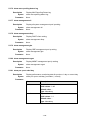
-5-
5.3.13
5.3.14
5.3.15
5.3.16
5.3.17
5.3.18
5.3.19
5.3.20
5.3.21
5.3.22
5.3.23
5.3.24
5.3.25
5.3.26
5.3.27
5.3.28
5.3.29
5.3.30
5.3.31
5.3.32
5.3.33
5.3.34
5.3.35
5.3.36
5.3.37
5.3.38
5.3.39
5.3.40
5.3.41
5.3.42
5.3.43
5.3.44
5.3.45
5.3.46
5.3.47
5.3.48
5.3.49
5.3.50
5.3.51
5.3.52
5.3.53
5.3.54
5.3.55
5.3.56
5.3.57
5.3.58
5.3.59
5.3.60
5.3.61
5.3.62
5.3.63
5.3.64
show account ........................................................................... 216
show aging ............................................................................... 216
show alarm current................................................................... 216
show alarm event ..................................................................... 216
show alarm history ................................................................... 216
show alarm aco ........................................................................ 216
show atmdesc .......................................................................... 216
show atm-loopback .................................................................. 217
show cli-config.......................................................................... 217
show cluster ............................................................................. 217
show cpu .................................................................................. 217
show dsl-line-identify ................................................................ 217
show fdb ................................................................................... 217
show fdbstatic .......................................................................... 218
show firmware .......................................................................... 218
show help ................................................................................. 218
show http .................................................................................. 218
show igmp ................................................................................ 218
show igmp group ...................................................................... 219
show igmp rtport....................................................................... 219
show igmp-acl bind gigabit ....................................................... 219
show igmp-acl bind gigabit la ................................................... 220
show igmp-acl bind xdsl ........................................................... 220
show interface xdsl {all | <port>} adsl carrier fe ds snr ............. 220
show interface xdsl {all | <port>} adsl carrier fe ds qln ............. 220
show interface xdsl {all | <port>} adsl carrier fe ds hlin ............ 221
show interface xdsl {all | <port>} adsl carrier fe ds hlog ........... 221
show interface xdsl {all | <port>} adsl carrier fe us load ........... 221
show interface xdsl {all | <port>} adsl carrier fe us gain ........... 221
show interface xdsl {all | <port>} adsl carrier fe us tss ............. 222
show interface xdsl {all | <port>} adsl carrier ne us snr ............ 222
show interface xdsl {all | <port>} adsl carrier ne us qln ............ 222
show interface xdsl {all | <port>} adsl carrier ne us hlin ........... 223
show interface xdsl {all | <port>} adsl carrier ne us hlog .......... 223
show interface xdsl {all | <port>} adsl carrier ne ds load .......... 223
show interface xdsl {all | <port>} adsl carrier ne ds gain .......... 223
show interface xdsl {all | <port>} adsl carrier ne ds tss ............ 224
show interface xdsl {all | <port>} adsl channel ......................... 224
show interface xdsl {all | <port>} adsl failure ............................ 224
show interface xdsl {all | <port>} adsl line ................................ 224
show interface xdsl {all | <port>} adsl line config ...................... 225
show interface xdsl {all | <port>} adsl line delt-test................... 225
show interface xdsl {all | <port>} adsl line information.............. 225
show interface xdsl {all | <port>} adsl inventory ....................... 225
show interface xdsl {all | <port>} adsl operational .................... 226
show interface xdsl {all | <port>} bridge ................................... 226
show interface xdsl {all | <port>} cellcount ............................... 226
show interface xdsl {all | <port>} counter ................................. 226
show interface xdsl {all | <port>} ipoa....................................... 227
show interface xdsl {all | <port>} vc .......................................... 227
show interface xdsl {all | <port>} vlan ....................................... 227
show interface bridge ............................................................... 227
-6-
5.3.65
5.3.66
5.3.67
5.3.68
5.3.69
5.3.70
5.3.71
5.3.72
5.3.73
5.3.74
5.3.75
5.3.76
5.3.77
5.3.78
5.3.79
5.3.80
5.3.81
5.3.82
5.3.83
5.3.84
5.3.85
5.3.86
5.3.87
5.3.88
5.3.89
5.3.90
5.3.91
5.3.92
5.3.93
5.3.94
5.3.95
5.3.96
5.3.97
5.3.98
5.3.99
5.3.100
5.3.101
5.3.102
5.3.103
5.3.104
5.3.105
5.3.106
5.3.107
5.3.108
5.3.109
5.3.110
5.3.111
5.3.112
5.3.113
5.3.114
5.3.115
5.3.116
show interface counter ............................................................. 227
show interface gigabit [<port>] bridge ...................................... 228
show interface gigabit [<port>] counter .................................... 228
show interface gigabit [<port>] stp ........................................... 228
show interface gigabit [<port>] vlan.......................................... 229
show interface gigabit la bridge ................................................ 229
show interface gigabit la counter .............................................. 229
show interface gigabit la lacp ................................................... 229
show interface gigabit la vlan ................................................... 229
show lacp ................................................................................. 229
show mac-spoofing-detect config ............................................. 229
show mac-spoofing-detect log.................................................. 230
show management all .............................................................. 230
show management dhcp .......................................................... 230
show management gbe ............................................................ 230
show management mgmt ......................................................... 230
show pm <port> adsl day ......................................................... 230
show pm <port> adsl interval ................................................... 231
show port-template parameter ................................................. 231
show priority-list ds................................................................... 231
show priority-list dstip ............................................................... 231
show priority-list dstmac ........................................................... 232
show priority-list ethertype ....................................................... 232
show priority-list ipprotocol ....................................................... 232
show priority-list srcip ............................................................... 232
show priority-list srcmac ........................................................... 233
show priority-list tos.................................................................. 233
show priority-list vlanid ............................................................. 233
show priority-queue config ....................................................... 233
show priority-regen................................................................... 233
show profile alarm all ............................................................... 234
show profile igmp-acl ............................................................... 234
show profile rate-limit policer .................................................... 234
show profile service adsl .......................................................... 234
show profile spectrum adsl ....................................................... 234
show profile tca adsl ......................................................... 235
show rmon alarm .............................................................. 235
show rmon ether_history ................................................... 235
show rmon event............................................................... 235
show rmon history ............................................................. 236
show rmon log................................................................... 236
show rmon statistic ........................................................... 236
show route ........................................................................ 236
show runningcfg ................................................................ 236
show runningcfg interface xdsl .......................................... 237
show runningcfg interface gigabit...................................... 237
show snmp ........................................................................ 237
show sntp .......................................................................... 237
show stp ............................................................................ 237
show syslog server ........................................................... 237
show system ..................................................................... 238
show tcm config ................................................................ 238
-7-
5.4
5.3.117
show tcm-policer ............................................................... 238
5.3.118
show temperature ............................................................. 238
5.3.119
show time .......................................................................... 238
5.3.120
show uptime ...................................................................... 238
5.3.121
show version ..................................................................... 238
5.3.122
show version detail ........................................................... 238
5.3.123
show vlan .......................................................................... 239
5.3.124
show vlan ethertype .......................................................... 239
5.3.125
show vlan protocol-base ................................................... 239
5.3.126
show vlan-translation one-to-one ...................................... 239
5.3.127
show vlan-translation many-to-one ................................... 239
5.3.128
telnet ................................................................................. 239
5.3.129
traceroute .......................................................................... 240
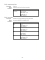
Configure Mode Commands ....................................................................... 241
5.4.1
access-list ................................................................................ 241
5.4.2
account add ............................................................................. 241
5.4.3
account delete .......................................................................... 242
5.4.4
account modify ......................................................................... 242
5.4.5
aging ........................................................................................ 243
5.4.6
alarm aco active ....................................................................... 243
5.4.7
alarm event clear...................................................................... 243
5.4.8
alarm history clear .................................................................... 243
5.4.9
atmdesc ................................................................................... 243
5.4.10
atm-loopback............................................................................ 244
5.4.11
cli-config session ...................................................................... 244
5.4.12
cli-config timeout ...................................................................... 244
5.4.13
cluster-cfg domain .................................................................... 245
5.4.14
cluster-cfg management ........................................................... 245
5.4.15
cluster-cfg name....................................................................... 245
5.4.16
cluster-cfg role.......................................................................... 245
5.4.17
cluster-cfg voting-key ............................................................... 246
5.4.18
dsl-line-identify dhcp ................................................................ 246
5.4.19
dsl-line-identify dhcp option82 circuit ....................................... 246
5.4.20
dsl-line-identify dhcp option82 dslam-name ............................. 246
5.4.21
dsl-line-identify dhcp option82 dslam-name-cluster ................. 246
5.4.22
dsl-line-identify dhcp option82 dslam-name-customer ............. 246
5.4.23
dsl-line-identify dhcp option82 sub ........................................... 247
5.4.24
dsl-line-identify dhcp option82 remote...................................... 247
5.4.25
dsl-line-identify pppoe srv-name .............................................. 247
5.4.26
dsl-line-identify pppoe srv-name-check .................................... 247
5.4.27
fdbstatic <number> {xdsl | gigabit} ........................................... 248
5.4.28
fdbstatic <number> disable ...................................................... 248
5.4.29
fdbstatic list .............................................................................. 249
5.4.30
firmware bootcode-upgrade ..................................................... 249
5.4.31
firmware login ........................................................................... 249
5.4.32
firmware partition...................................................................... 250
5.4.33
firmware upgrade ..................................................................... 250
5.4.34
http port .................................................................................... 250
5.4.35
igmp acl.................................................................................... 250
5.4.36
igmp default ............................................................................. 250
5.4.37
igmp deny no-router-alert ......................................................... 251
5.4.38
igmp disable ............................................................................. 251
-8-
5.4.39
5.4.40
5.4.41
5.4.42
5.4.43
5.4.44
5.4.45
5.4.46
5.4.47
5.4.48
5.4.49
5.4.50
5.4.51
5.4.52
5.4.53
5.4.54
5.4.55
5.4.56
5.4.57
5.4.58
5.4.59
5.4.60
5.4.61
5.4.62
5.4.63
5.4.64
5.4.65
5.4.66
5.4.67
5.4.68
5.4.69
5.4.70
5.4.71
5.4.72
5.4.73
5.4.74
5.4.75
5.4.76
5.4.77
5.4.78
5.4.79
5.4.80
5.4.81
5.4.82
5.4.83
5.4.84
5.4.85
5.4.86
5.4.87
5.4.88
5.4.89
5.4.90
igmp max-group-limit................................................................ 251
igmp proxy ............................................................................... 251
igmp snooping .......................................................................... 251
igmp rtport gigabit .................................................................... 252
igmp rtport list........................................................................... 252
igmp timeout ............................................................................ 253
igmp version ............................................................................. 253
interface gigabit ........................................................................ 253
interface gigabit la .................................................................... 253
interface xdsl ............................................................................ 254
mac-spoofing-detect................................................................. 254
mac-spoofing-detect log ........................................................... 254
management dhcp ................................................................... 254
management dhcp timeout ....................................................... 254
management dhcp leasetime ................................................... 255
management gbe ..................................................................... 255
management gbe vlan.............................................................. 255
management gbe vlan priority .................................................. 256
management mgmt .................................................................. 256
pm clear ................................................................................... 256
port-template mask .................................................................. 257
port-template unmask .............................................................. 257
port-template template-port ...................................................... 257
priority-list ................................................................................. 257
priority-queue atm priority ........................................................ 258
priority-queue atm queue0-weight ............................................ 258
priority-queue atm queue1-weight ............................................ 258
priority-queue atm queue2-weight ............................................ 259
priority-queue atm queue3-weight ............................................ 259
priority-queue atm scheduling .................................................. 259
priority-queue gigabit priority .................................................... 259
profile alarm ............................................................................. 260
profile igmp-acl ......................................................................... 260
profile service adsl ................................................................... 260
profile spectrum........................................................................ 260
profile tca xdsl .......................................................................... 261
profile rate-limit......................................................................... 261
remotecfg login......................................................................... 261
restore-factory .......................................................................... 262
rmon alarm <index> alarm_interval .......................................... 262
rmon alarm <index> delete ...................................................... 262
rmon alarm <index> falling_eventindex.................................... 263
rmon alarm <index> falling_threshold ...................................... 263
rmon alarm <index> owner ...................................................... 263
rmon alarm <index> rising_eventindex .................................... 264
rmon alarm <index> rising_threshold ....................................... 264
rmon alarm <index> sample_type ............................................ 264
rmon alarm <index> startup_alarm .......................................... 265
rmon alarm <index> variable .................................................... 266
rmon event <index> community ............................................... 267
rmon event <index> delete ....................................................... 267
rmon event <index> description ............................................... 267
-9-
5.4.91
5.4.92
5.4.93
5.4.94
5.4.95
5.4.96
5.4.97
5.4.98
5.4.99
5.4.100
5.4.101
5.4.102
5.4.103
5.4.104
5.4.105
5.4.106
5.4.107
5.4.108
5.4.109
5.4.110
5.4.111
5.4.112
5.4.113
5.4.114
5.4.115
5.4.116
5.4.117
5.4.118
5.4.119
5.4.120
5.4.121
5.4.122
5.4.123
5.4.124
5.4.125
5.4.126
5.4.127
5.4.128
5.4.129
5.4.130
5.4.131
5.4.132
5.4.133
5.4.134
5.4.135
5.4.136
5.4.137
5.4.138
5.4.139
one-to-one
5.4.140
many-to-one
rmon event <index> owner ....................................................... 268
rmon event <index> type.......................................................... 268
rmon history <index> buckets_requested ................................ 268
rmon history <index> delete ..................................................... 269
rmon history <index> ifc ........................................................... 269
rmon history <index> interval ................................................... 269
rmon history <index> owner ..................................................... 270
rmon statistic <index> delete.................................................... 270
rmon statistic <index> ifc .......................................................... 270
rmon statistic <index> owner ............................................ 271
route .................................................................................. 271
route default ...................................................................... 271
route delete ....................................................................... 272
runningcfg active partition ................................................. 272
runningcfg load partition .................................................... 272
runningcfg login................................................................. 273
runningcfg write partition ................................................... 273
snmp <index> community ................................................. 273
snmp notify........................................................................ 274
snmp target <name> address ........................................... 274
snmp target <name> delete .............................................. 274
snmp target <name> tag-list ............................................. 275
snmp target <name> version ............................................ 275
sntp polling interval ........................................................... 275
sntp server address .......................................................... 276
stp ..................................................................................... 276
stp enable ......................................................................... 276
stp disable ......................................................................... 276
stp forward delay............................................................... 276
stp hello time ..................................................................... 277
stp max-age ...................................................................... 277
stp priority ......................................................................... 277
stp version......................................................................... 277
syslog server ..................................................................... 278
tcm color-aware ................................................................ 278
tcm color-field.................................................................... 278
tcm green .......................................................................... 278
tcm non-conform-pkt ......................................................... 278
tcm red .............................................................................. 279
tcm yellow ......................................................................... 279
temperature threshold ....................................................... 279
temperature shelf time ...................................................... 280
time set date ..................................................................... 280
time set time...................................................................... 281
time set timezone .............................................................. 281
trunk-mode ........................................................................ 283
vlan ethertype s-tag .......................................................... 283
vlan protocol-base............................................................. 284
vlan-translation <port>/<pvc> <VLAN ID> gigabit <port>
285
vlan-translation <port>/<pvc> <VLAN ID> gigabit <port>
286
- 10 -
5.4.141
5.5
5.6
5.7
5.8
vlan-translation <port>/<pvc> <VLAN ID> gigabit la one-to-one
287
5.4.142
vlan-translation <port>/<pvc> <VLAN ID> gigabit la
many-to-one
288
5.4.143
vlan-translation <port>/<pvc> <VLAN ID> disable ............ 289
Ethernet Interface Mode Commands ......................................................... 290
5.5.1
bridge ....................................................................................... 290
5.5.2
gbe admin ................................................................................ 290
5.5.3
gbe speed ................................................................................ 290
Interface Mode Commands ......................................................................... 291
5.6.1
bridge ....................................................................................... 291
5.6.2
adsl-config ................................................................................ 291
5.6.3
ipoa .......................................................................................... 291
ATM Bridge Mode Commands .................................................................... 292
5.7.1
accfrm ...................................................................................... 292
5.7.2
default vlan ............................................................................... 292
5.7.3
default prio ............................................................................... 292
5.7.4
dhcp-relay ................................................................................ 293
5.7.5
egress ...................................................................................... 293
5.7.6
force priority ............................................................................. 293
5.7.7
igmp-acl bind ............................................................................ 293
5.7.8
igmp-acl max-group ................................................................. 294
5.7.9
ingress ..................................................................................... 294
5.7.10
ip-allowed ................................................................................. 294
5.7.11
isolation .................................................................................... 294
5.7.12
mac-learning ............................................................................ 294
5.7.13
max-mac .................................................................................. 294
5.7.14
priority-regen ............................................................................ 295
5.7.15
protocol-base ........................................................................... 295
5.7.16
pvc ........................................................................................... 295
5.7.17
pvc atmdesc ............................................................................. 295
5.7.18
pvc atmdesc plc ....................................................................... 296
5.7.19
pvc atmdesc shp ...................................................................... 296
5.7.20
pvc encapsulation .................................................................... 296
5.7.21
stack......................................................................................... 297
5.7.22
stack tls port enable ................................................................. 297
5.7.23
tcm-policer ............................................................................... 297
5.7.24
vlan <VLAN ID> disable ........................................................... 297
5.7.25
vlan <VLAN ID> list .................................................................. 297
5.7.26
vlan <VLAN ID> priority ............................................................ 298
5.7.27
vlan list ..................................................................................... 298
GBE Bridge Mode Commands.................................................................... 299
5.8.1
accfrm ...................................................................................... 299
5.8.2
default vlan ............................................................................... 299
5.8.3
default prio ............................................................................... 299
5.8.4
egress ...................................................................................... 299
5.8.5
ingress ..................................................................................... 299
5.8.6
isolation .................................................................................... 300
5.8.7
link mode .................................................................................. 300
5.8.8
max-mac .................................................................................. 300
5.8.9
priority-regen ............................................................................ 300
5.8.10
stack......................................................................................... 300
- 11 -
5.9
5.10
5.11
5.12
5.8.11
stpport edge ............................................................................. 301
5.8.12
stpport enable/disable .............................................................. 301
5.8.13
stpport pathcost........................................................................ 301
5.8.14
stpport priority .......................................................................... 301
5.8.15
tcm-policer ............................................................................... 301
5.8.16
vlan <VLAN ID> disable ........................................................... 302
5.8.17
vlan <VLAN ID> list .................................................................. 302
5.8.18
vlan <VLAN ID> priority ............................................................ 302
5.8.19
vlan list ..................................................................................... 303
GBE-LA Bridge Mode Commands .............................................................. 304
5.9.1
accfrm ...................................................................................... 304
5.9.2
default vlan ............................................................................... 304
5.9.3
default prio ............................................................................... 304
5.9.4
egress ...................................................................................... 304
5.9.5
ingress ..................................................................................... 304
5.9.6
isolation .................................................................................... 305
5.9.7
lacp actor priority system ......................................................... 305
5.9.8
link mode .................................................................................. 305
5.9.9
max-mac .................................................................................. 305
5.9.10
priority-regen ............................................................................ 306
5.9.11
stack......................................................................................... 306
5.9.12
tcm-policer ............................................................................... 306
5.9.13
vlan <VLAN ID> disable ........................................................... 306
5.9.14
vlan <VLAN ID> list .................................................................. 307
5.9.15
vlan <VLAN ID> priority ............................................................ 307
5.9.16
vlan list ..................................................................................... 307
ADSL Configure Mode Commands ............................................................ 308
5.10.1
line mode carrier ...................................................................... 308
5.10.2
line mode diagnostic ................................................................ 308
5.10.3
line mode force-l3..................................................................... 308
5.10.4
line mode mask ........................................................................ 308
5.10.5
line port .................................................................................... 309
5.10.6
line profile ................................................................................. 309
5.10.7
line status service ..................................................................... 309
IPoA Configure Mode Commands .............................................................. 310
5.11.1
brasmac ................................................................................... 310
5.11.2
brasmac list .............................................................................. 310
5.11.3
cpriority .................................................................................... 310
5.11.4
cvlan ......................................................................................... 310
5.11.5
ipoa-status................................................................................ 311
5.11.6
max-mac .................................................................................. 311
5.11.7
pvc ........................................................................................... 311
5.11.8
pvc atmdesc ............................................................................. 311
5.11.9
pvc atmdesc plc ....................................................................... 312
5.11.10
pvc atmdesc shp ............................................................... 312
5.11.11
pvc encapsulation ............................................................. 312
5.11.12
uplink gigabit ..................................................................... 312
Access List Mode Commands .................................................................... 313
5.12.1
bcrate cir .................................................................................. 313
5.12.2
bcrate list.................................................................................. 313
5.12.3
dstmac ..................................................................................... 314
5.12.4
dstmac list ................................................................................ 314
- 12 -
5.13
5.14
5.15
5.12.5
dstip ......................................................................................... 315
5.12.6
dstip list .................................................................................... 315
5.12.7
ethertype .................................................................................. 316
5.12.8
ethertype list ............................................................................. 316
5.12.9
ip-allowed ................................................................................. 317
5.12.10
ip-allowed list .................................................................... 317
5.12.11
ipprotocol .......................................................................... 318
5.12.12
ipprotocol list ..................................................................... 319
5.12.13
l4dstport ............................................................................ 319
5.12.14
l4dstport list ....................................................................... 319
5.12.15
mcfldrate list ...................................................................... 320
5.12.16
mcfldrate vlan.................................................................... 320
5.12.17
srcip .................................................................................. 321
5.12.18
srcip list ............................................................................. 321
5.12.19
srcmac .............................................................................. 322
5.12.20
srcmac list ......................................................................... 322
ATM Description Mode Commands............................................................ 323
5.13.1
cbr ............................................................................................ 323
5.13.2
no atmdesc .............................................................................. 323
5.13.3
ubr1 .......................................................................................... 324
5.13.4
ubr2 .......................................................................................... 324
5.13.5
unshp ....................................................................................... 325
5.13.6
vbr1 .......................................................................................... 325
5.13.7
vbr2 .......................................................................................... 326
5.13.8
vbr3 .......................................................................................... 327
5.13.9
ubr-shp ..................................................................................... 328
5.13.10
cbr-shp .............................................................................. 328
5.13.11
vbr-shp .............................................................................. 329
5.13.12
vbrnrt ................................................................................. 330
Priority List Mode Commands .................................................................... 331
5.14.1
ds ............................................................................................. 331
5.14.2
ds list ........................................................................................ 332
5.14.3
dstip ......................................................................................... 332
5.14.4
dstip list .................................................................................... 333
5.14.5
dstmac ..................................................................................... 333
5.14.6
dstmac list ................................................................................ 334
5.14.7
ethertype .................................................................................. 334
5.14.8
ethertype list ............................................................................. 335
5.14.9
ipprotocol ................................................................................. 335
5.14.10
ipprotocol list ..................................................................... 336
5.14.11
srcip .................................................................................. 336
5.14.12
srcip list ............................................................................. 337
5.14.13
srcmac .............................................................................. 337
5.14.14
srcmac list ......................................................................... 338
5.14.15
tos ..................................................................................... 338
5.14.16
tos list ................................................................................ 339
5.14.17
vlanid ................................................................................ 339
5.14.18
vlanid list ........................................................................... 339
Alarm Profile Mode Commands ................................................................. 340
5.15.1
alarm mask .............................................................................. 340
5.15.2
alarm unmask........................................................................... 340
5.15.3
alarm major .............................................................................. 340
- 13 -
5.15.4
alarm minor .............................................................................. 341
5.16
IGMP-ACL Profile Mode Commands .......................................................... 342
5.16.1
igmp-acl ................................................................................... 342
5.16.2
igmp-acl rebind......................................................................... 342
5.17
Rate Limit Profile Mode Commands .......................................................... 343
5.17.1
share-slb .................................................................................. 343
5.17.2
share-dlb .................................................................................. 343
5.17.3
non-share-slb ........................................................................... 344
5.17.4
non-share-dlb ........................................................................... 344
5.18
Service Profile Configure Mode Commands ............................................. 346
5.18.1
bitrate ....................................................................................... 346
5.18.2
delay ........................................................................................ 346
5.18.3
l2-packet................................................................................... 346
5.18.4
mode ........................................................................................ 346
5.18.5
noise ........................................................................................ 347
5.18.6
noisemargin ............................................................................. 347
5.18.7
ra-interval ................................................................................. 347
5.18.8
service name ............................................................................ 347
5.19
Spectrum Profile Configure Mode Commands ......................................... 348
5.19.1
aggregate ................................................................................. 348
5.19.2
bands <index> {start | stop}...................................................... 348
5.19.3
bands <index> mask ................................................................ 348
5.19.4
carriermask .............................................................................. 349
5.19.5
message-based........................................................................ 349
5.19.6
modem features ....................................................................... 349
5.19.7
noisemargin ............................................................................. 350
5.19.8
opmode .................................................................................... 350
5.19.9
pbomode .................................................................................. 350
5.19.10
power-mgt disable............................................................. 350
5.19.11
power-mgt l2 enable ......................................................... 350
5.19.12
power-mgt l2_l3 enable ..................................................... 351
5.19.13
power-mgt l0-time ............................................................. 351
5.19.14
power-mgt l2-time ............................................................. 351
5.19.15
power-mgt l2-atpr .............................................................. 351
5.19.16
power-mgt l2-atprt ............................................................. 352
5.19.17
psdlevel ............................................................................. 352
5.19.18
psdshape .......................................................................... 352
5.19.19
rxaggregate us max powerlevel ........................................ 353
5.19.20
spectrum name ................................................................. 353
5.19.21
status modify complete ..................................................... 353
5.20
TCA Profile Mode Commands .................................................................... 354
5.20.1
adsl-tca day .............................................................................. 354
5.20.2
adsl-tca disable ........................................................................ 354
5.20.3
adsl-tca enable ......................................................................... 354
5.20.4
adsl-tca interval ........................................................................ 354
Appendix A ADSL Operational Mask Table .............................................................. 355
Appendix B Alarm Table ............................................................................................ 356
Appendix C Maintenance Requirement ................................................................... 357
Appendix D Introduction for Troubleshooting ........................................................ 361
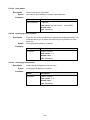
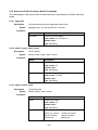
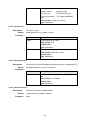
- 14 -
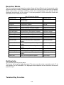
Introduction
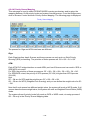
The PLANET IDL-4802 is a 48-Port ADSL/ADSL2/ADSL2+ mini IP DSLAM which equips
with combo electrical (RJ-45) and fiber optical (SFP) uplink interfaces offering scalable and
easy deployment for the network with small ADSL environment. With the built-in POTS
splitter subscriber ports, the IDL-4802 performs a cost-effective solution for network service
providers to offer multiple subscribers excellent services.
Moreover, the IDL-4802 supports local and remote managed capabilities of CLI, SNMP,
and Telnet via RS-232 console port and Web GUI management interface. Via user-friendly
Web GUI, the IDL-4802 can be managed by workstations running standard web browsers
that provide the easy-to-use operation and convenient maintenance.
To enhance the network security, the PLANET IDL-4802 also provides features such as
QoS, VLAN, Multicast, Bandwidth Management, Traffic Prioritization, and Access Control
List. With the advanced QoS features, the IDL-4802 is an ideal solution for next generation
broadband network to deliver rich video contents, DSL, POTS, and VoIP service over
ADSL2+ connection.
1.1 Product Features
48-Port ADSL / ADSL2 / ADSL2+ Subscriber Interface with Built-in POTS Splitter
DMT data rate: Downstream up to 25 Mbps / Upstream up to 3Mbps
2 x 1000Base-T or 2 x mini-GbE Uplink Interfaces
Web-based GUI Management
Local RS-232 CLI and Ethernet SNMP / Telnet / SSH Management
Firmware Upgradeable via FTP
Configuration Backup and Restoration via TFTP
Supports IPSec / L2TP / PPTP VPN Pass-through
Supports 4K MAC address
Supports IEEE 802.1q Tag-based VLAN and Protocol-based VLAN
Layer 2 / 3 Filtering Based on MAC, IP, Protocol, Port Number and Ether Type
Access Control List by MAC / IP / Protocol / Port number
Traffic prioritization (802.1p)
Supports IGMP Snooping / Proxy per IGMP v1, v2, and v3
FAN Alarm Indicating
Temperature Monitoring and System Overheating Trap Functionality
Supports IEEE 802.1d Spanning Tree Protocol and IEEE 802.3ad Link Aggregation
- 15 -
1.2 Package Contents
IDL-4802
IDL-4802 Unit x 1
AC Power Cord x 1
CD x 1
Quick Installation Guide x 1
2-Meter Telco-50 Cable x 4
Console Cable x 1
Rack-mounting Ear x 2
Screw Package x 2
Connect Tenon x 4
RJ-45 Cable for Fan x 1
IDL-4802-48
IDL-4802-48Unit x 1
DC Power Terminal Block x 1
CD x 1
Quick Installation Guide x 1
2-Meter Telco-50 Cable x 4
Console Cable x 1
Rack-mounting Ear x 2
Screw Package x 2
Connect Tenon x 4
RJ-45 Cable for Fan x 1
If any of above items are damaged or missing, please contact your dealer immediately.
- 16 -
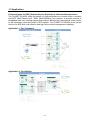
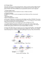
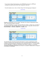
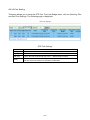
1.3 Application
Perfect solution for NSP (Network Service Provider) to offer broadband services
The PLANET IDL-4802 offers the benefit of high performance to central office co-location
and MTU (Multi-Tenant Unit) / MDU (Multi-Dwelling Unit) markets. It provides service of
broadband data over existing copper wires without affecting the conventional voice service
by 48 subscriber ports with built-in POTS splitter. The PLANET IP DSLAM is the perfect
solution for NSP with cost-effective and high-value central management capability.
Application 1: For Community
Application 2: For Building
- 17 -
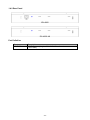
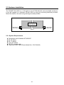
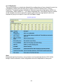
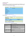
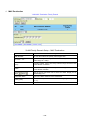
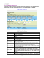
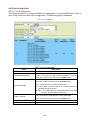
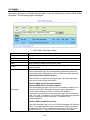
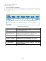
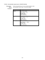
1.4 Outlook
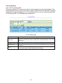
1.4.1 Front Panel
IDL-4802
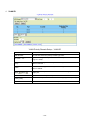
IDL-4802-48
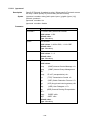
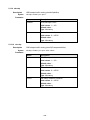
Interface Definition
Interface
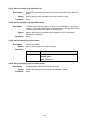
POWER
Description
Power On / Off switch.
-48V DC Power plug-in.
(*IDL-4802-48)
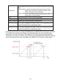
RJ-45 port for connection with the RJ-45 port on the front panel of fan card to
provide power to the fan.
RJ-50 port for housekeeping inputs and one alarm contact output.
RS-232 port for system configuration and maintenance. (9600, 8, N, 1)
A hidden reset button for hardware resetting.
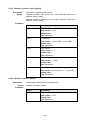
Alarm Cut Off
Ethernet Port connected to LAN for providing system out-band Telnet control
interface, such as system monitor, control or software upgrade.
Gigabit Ethernet electrical trunk ports.
Gigabit Ethernet SFP trunk ports.
RJ-21 connector for connecting POTS lines.
RJ-21 connector for connecting DSL lines.
-48V
FAN
HK
Console
RST
ACO
MGMT
Uplink 1 & 2
SFP 1 & 2
PHONE 1 & 2
LINE 1 & 2
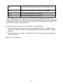
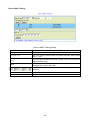
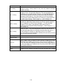
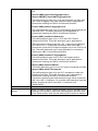
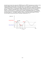
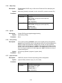
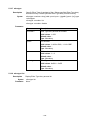
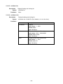
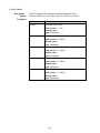
LED Definition
LED
Color
Orange
Uplink
Green
SYS
ALM
DSL status
On
Off
On
Off
Flash
Green
Red
Green
Red
Green
On
Off
Flash
Description
Uplink Port connect with 100/1000Mbps Ethernet link
Uplink Port connect with 10Mbps Ethernet link
Active
Inactive
Uplink Port Transmit / receive data
Normal Operation
Self-test fail
Normal Operation
To indicate the system alarm status
ADSL Port is activated and linked
ADSL Port is Disabled
ADSL Port is activated but not linked
- 18 -
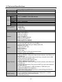
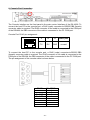
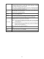
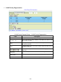
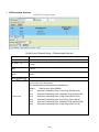
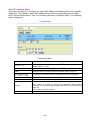
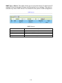
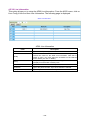
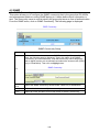
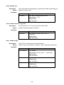
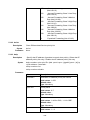
1.4.2 Rear Panel
IDL-4802
IDL-4802-48
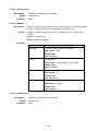
Port Definition
Port
AC PWR
Description
AC Power cord plug-in, 100 - 240VAC is allowed.
(*IDL-4802)
- 19 -
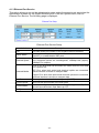
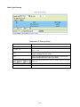
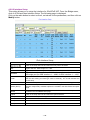
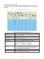
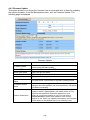
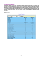
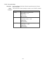
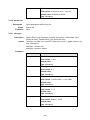
1.5 Technical Specifications
Product
48-Port ADSL 2/2+ IP DSLAM
Model
IDL-4802 / IDL-4802-48
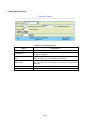
Hardware Specification
Case
1.5U high box-type with a rack-mountable enclosure
2 x RJ-45 (10/100/1000Base-T)
Uplink
2 x SFP (1000Base-T/SX/LX/EX/ZX/LHX)
MGMT
1 x RJ-45 (10/100Base-TX)
Console
1 x RJ-45 (RS-232 serial port, 9600, 8, N, 1)
Ports
LINE
2 x RJ-21 connectors
PHONE
2 x RJ-21 connectors
Fan
2 x RJ-45
HK
1 x RJ-50
1 x SYS LED
1 x ALM LED
LED Indicators
2 x Uplink LEDs
48 x ADSL LEDs
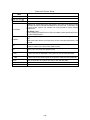
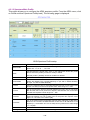
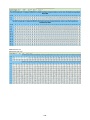
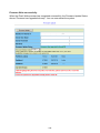
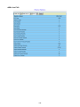
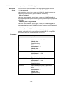
Software Specification
Compliant with ADSL standard
− ANSI T1.413 issue 2
− G.dmt (ITU G.992.1)
− G.lite (ITU G.992.2)
Standard
− G.hs (ITU G.994.1)
Capable of ADSL2 standard
− G.dmt.bis (ITU G.992.3)
Capable of ADSL2+ standard
− G.dmt.bisplus (ITU G.992.5)
− Subscriber interface with built-in POTS splitter
− Downstream DMT data rate up to 25 Mbps
− Upstream DMT data rate up to 3 Mbps (Annex M)
− Distance up to 18 kft
− 8 PVCs per xDSL port
System
− DHCP forward
− DHCP relay agent
− PPPoE relay
− IPSec/L2TP/PPTP VPN pass-through function
− PPPoA to PPPoE inter-working
− Supports IPv4 packet
− Supports IEEE802.1d Ethernet bridge function between trunk Ether port
and ATM VCs
− Supports static source MAC table provisioning, automatic source MAC
learning and block duplicate ones
− Supports 4K static MAC address table
− 128 MAC address per x DSL port
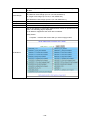
Bridge Function
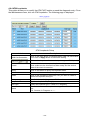
− Supports IEEE802.1d Ethernet bridge function between trunk Ether port
and ATM VCs
− Supports Rapid Spanning Tree Protocol (RSTP) for the trunk interfaces
per IEEE 802.1w
− Support Link Aggregation in IEEE 802.3ad for 2 GBE links to be
aggregated together as a logical link
− Support both LACP protocol (dynamic) for load sharing and failover in
case of loss of Ethernet link
− IEEE 802.1q Port-based / Protocol-based VLAN
− 512 non-stacked VLAN-ID simultaneously ranging from 1 to 4095
VLAN Function
− VLAN stacking and VLAN cross-connect
− IP Spoofing prevention
- 20 -
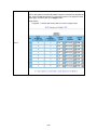
−
−
−
MAC anti-Spoofing
Port isolation functionality
Static VLAN group and membership provisioning
− IP multicast forwarding
− Complies with RFC2684 bridged payload encapsulation mode
− Up to 256 multicast groups and 512 copies simultaneously
Multicast Function − Up to 48 profile-based Multicast Access Control
− Limit maximum number of IGMP groups joined per bridge port
− IGMP snooping / proxy per IGMP v1, v2, and v3
− IGMP proxy and IGMP snooping Selection
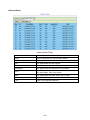
− Supports Layer-2 frame filtering based on MAC and Ether Type
Security
− Supports Layer-3 filtering based on IP, Protocol, and Port number
− IEEE 802.1X authentication
− Control the bandwidth occupied by broadcast, multicast, and unknown
unicast (flooding)
− Rate-limit profile binding per bridge port
− Three Color Marking (TCM) policer
− Ethernet rate limit per bridge port
− ToS (type of service) / DiffServ (differentiated services) stripping and
QoS
priority queuing
− DSCP mapping to 802.1p
− Selectable adopted priority queue mechanisms according to Strict Priority
Queue (SPQ) and Weighted Fair Queue (WFQ)
− Configurable mapping function between ATM PVC and 802.1p priority
queue
− Supports IP CoS technology
− Web based GUI management
− Local RS-232 CLI, and Ethernet SNMP / Telnet / SSH management
Management
− Remote in-band SNMP / Telnet / SSH management
− Firmware upgradeable via FTP
SNMP v1, v2c
- 21 -
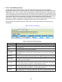
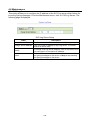
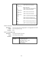
Installation
The followings are instructions for setting up the IDL-4802. Refer to the illustration and
follow the simple steps below to quickly install your IP DSLAM.
2.1 Safety Instruction
The following is the safety instructions for IP DSLAM before installing.
>> The maximum operating temperature of the IP DSLAM is 65ºC. Care must be taken to
allow sufficient air circulation or space between units when the IP DSLAM is installed
inside a closed rack assembly and racks should safely support the combined weight of all
IP DSLAM.
>> The connections and equipment that supply power to the IP DSLAM should be capable
of operating safely with the maximum power requirements of the IP DSLAM. In the event
of a power overload, the supply circuits and supply wiring should not become hazardous.
>> The AC power cord must plug into the right supply voltage. Make sure that the supplied
AC voltage is correct and stable. If the input AC voltage is over 10% lower than the
standard may cause the IP DSLAM to malfunction.
>> Generally, when installed after the final configuration, the product must comply with the
applicable safety standards and regulatory requirements of the country in which it is
installed. If necessary, consult for technical support.
>> A rare condition can create a voltage potential between the earth grounds of two or
more buildings. If products installed in separate building are interconnected, the voltage
potential can cause a hazardous condition. Consult a qualified electrical consultant to
determine whether or not this phenomenon exists and, if necessary, implement corrective
action before interconnecting the products. If the equipment is to be used with
telecommunications circuit, take the following precautions:
- Never install telephone wiring during a lightning storm.
- Never install telephone jacks in wet location unless the jack is specially - designed for
wet location.
- Never touch un-insulated telephone wires or terminals unless the telephone line has
been disconnected at the network interface.
- Caution when installing or modifying telephone lines (other than a cordless telephone)
during an electrical storm. There is a remote risk of electric shock from lightning.
- Do not use a telephone or other equipment connected to telephone lines to report a
gas leak in the vicinity of the leak.
- 22 -
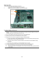
2.2 Hardware Installation
The PLANET IDL-4802 is a 1.5U high box-type IP DSLAM with rack-mountable enclosure.
It can be installed in a standard 19-inch rack by using the mounting brackets provided.
Mount the shelf on the rack using the large screws provided.
STANDARD
FRONT MOUNT
MOUNTING
BRACKET
MOUNTING
BRACKET
FRONT
2.2.1 System Requirements
Workstation with Windows NT/2000/XP
RJ-45 cables
RJ-11 cables
Telco-50 cables
RS-232 console cable
<Optional> MDF Patch Panel (Model No.: IDL-PAN-48)
- 23 -
2.2.2 Installation Procedure
1. Power and Ground Connections
Power Connections
With IDL-4802, connect the ac power cord to the ac supply socket on the rear panel as
below figure, and plug the cord into the external power source. The voltage must be 100 to
240V AC.
With IDL-4802-48, the DC power interface is a 4-pin terminal block with polarity signs on
the front panel as below figure.
It can be powered from two –48V DC power supply. The DC power connector is a 4P
terminal block; 2P is for accommodating one DC power input and other 2P is for
accommodating another DC power input. The DC power should be connected to a
well-fused power supply.
After completing chassis installation, please apply power to the fused power distribution
panel feeding the chassis. When using a DC voltmeter, please check for proper voltage:
-60V ~ -36V DC, and make sure that the polarity is correct.
Note:
1. Ensure that all power sources to the device are turned off during the installation.
2. It is recommended that the -48VDC power be supplied directly and independently by a
power feeding system and also avoid having a parallel or mutual connection with other
-48VDC power supplier of telecom equipment. This is to guarantee our products against
interferences by other equipment while they are working.
Ground Connections
- 24 -
In Central Office:
Ther should be a co gnd that is adequately grounded. If the measured resistance from the
grounding screw (on the rear panel of the dslam, refer to below figure) to co gnd is less than
5 ohm, then it can be assumed that the system is well grounded. If the measured resistance
is larger than 5 ohm, it is recommended to connect the grounding screw to co gnd using
#14 or #12 awg wire gauge conductor.
In Remote Cabinet:
The IDL-4802 should be grounded by connecting a #14 or #12 AWG conductor between
the grounding screw (on the rear panel of the DSLAM, refer to below figure) and the earth
ground or main grounding bar. The resistance between the chassis and the grounding bar
should be less than 25 Ohm.
Grounding Screw of IDL-4802
Grounding Screw of IDL-4802-48
- 25 -
2: FAN Cable Connection
There are two FAN ports on the front panel. One is on the FAN card; the other is beside the
HK port. To make the fans work, you must use an RJ45-to-RJ45 connector cable to connect
the two FAN ports.
FAN Port RJ-45 pin assignment:
12345678
3,4
5
6
7
8
GND
FAN
ERR1
FAN
ERR2
FAN
ERR3
FAN
Status
- 26 -
3: ADSL and POTS Connections
The IDL-4802 supports 48 ports ADSL subscribers per box. There are four RJ-21 50-pin
female connectors on the front panel of the system. Two for ADSL lines and two for POTS
interfaces.
To connect the subscriber lines, use cables with the RJ-21 50-pin male connectors. When
installing, just plug the end of cable with connector into the LINE and PHONE connectors
on the front panel. The other end of the cable is generally tied to the MDF (Main Distribution
Frame).
Note:
The MDF Patch panel is optional of standard package.
Please plug-in the RJ-21 cable with connector tenon as below figures.
- 27 -
LINE / PHONE interface pin assignment:
For port 1~24:
25
1
50
26
PIN
Number
1
2
3
4
5
6
7
8
~
18
19
20
21
22
23
24
25
Port
Number
Tip
1
Tip
2
Tip
3
Tip
4
Tip
5
Tip
6
Tip
7
Tip
8
~
~
Tip
18
Tip
19
Tip
20
Tip
21
Tip
22
Tip
23
Tip
24
X
PIN
Number
26
27
28
29
30
31
32
33
~
43
44
45
46
47
48
49
50
Port
Number
Ring Ring Ring Ring Ring Ring Ring Ring
1
2
3
4
5
6
7
8
~
Ring Ring Ring Ring Ring Ring Ring
18
19
20
21
22
23
24
X
For port 25~48:
26
50
1
25
PIN
Number
1
2
3
4
5
6
7
8
~
18
19
20
21
22
23
24
25
Port
Number
Tip
25
Tip
26
Tip
27
Tip
28
Tip
29
Tip
30
Tip
31
Tip
32
~
~
Tip
42
Tip
43
Tip
44
Tip
45
Tip
46
Tip
47
Tip
48
X
PIN
Number
26
27
28
29
30
31
32
33
~
43
44
45
46
47
48
49
50
Port
Number
Ring Ring Ring Ring Ring Ring Ring Ring
25
26
27
28
29
30
31
32
- 28 -
~
Ring Ring Ring Ring Ring Ring Ring
42
43
44
45
46
47
48
X
4:
Uplink Interfaces Connections
The system provides two types of trunk interfaces (two ports for each type). There are
electrical (RJ-45) and optical (SFP) interfaces. When both electrical and optical ports are
connected, system will automatically select the interface according to the priority setting
(Fiber first or Copper first).
RJ-45 electrical trunk port pin assignment:
1,2
T/Rx+,T/Rx-
3,6
T/Rx+,T/Rx-
4,5
T/Rx+,T/Rx-
7,8
T/Rx+,T/Rx-
SFP (Mini-GBIC):
Prepare a proper SFP module and install it into the optical trunk port. Then you can connect
fiber optics cabling that uses LC connectors or SC connectors (with the use of an optional
SC-to-LC adapter) to the fiber optics connector on the trunk port.
- 29 -
5: Management Port Connection
The IDL-4802 provides one RJ45 (MGMT) on the front panel for Ethernet interface
connection. To connect the Ethernet interface to PC directly, an Ethernet crossover cable is
required.
Ethernet Port RJ-45 pin assignment:
1
2
3
6
Other pins
TX +
TX -
RX +
RX -
Bob Smith
Termination
To connect the Ethernet interface to PC, the Ethernet crossover cable is required. The
detailed pin assignment is shown below.
Green/White
8
1
Orange
Green
7
2
Orange/White
Orange/White
6
3
Brown
Blue
5
4
Blue/White
Blue/White
4
5
Blue
Orange
3
6
Brown/White
Brown/White
2
7
Green
Brown
1
8
Green/White
Name
Pin
Pin
Name
Tx+
1
3
Rx+
Tx-
2
6
Rx-
Rx+
3
1
Tx+
Rx-
6
2
Tx-
- 30 -
6: Console Port Connection
The Console interface on the front panel is the main control interface of the IDL-4802. To
connect the host PC to the console port, a RJ45 (male) connector-to-RS232 DB9 (female)
connector cable is required. The RJ45 connector of the cable is connected to the COM port
of the DSLAM; the DB9 connector of the cable is connected to the PC COM port.
Console Port RJ-45 pin assignment:
12345678
3
4
6
Other pins
TX
RX
GND
unused
To connect the host PC to the console port, a RJ45 (male) connector-to-RS232 DB9
(female) connector cable is required. The RJ45 connector of the cable is connected to the
COM port of the DSLAM; the DB9 connector of the cable is connected to the PC COM port.
The pin assignment of the console cable is shown below:
DB-9F
Pin 2 RD
Pin 3 TD
Pin 5 DGND
RJ-45M Pin
1
2
3
4
5
6
7
8
- 31 -
7: Housekeeping Connection
The IDL-4802 equips with a RJ-50 port (HK) on the front panel to provide four
housekeeping inputs and one alarm contact output. Generally, housekeeping contacts can
connect to environment-sensor-controlled switch to indicate the operation environment
condition.
The HK circuit contains a photo coupler powered by the IDL-4802 to detect the “open” or
“close” status of the loop between HK_IN and HK_COM (users don’t need to feed 3.3v
power into the circuit). As to the alarm output, there is a relay between ALMOUT and
ALMCOM to control the status of the loop to be “OPEN” or “CLOSE” to the alarm
equipment (close between ALMOUT and ALMCOM for alarm; open if no alarm).
HK Port RJ-50 pin assignment:
Note:
The maximum current and voltage for ALMOUT / ALMCOM is restricted to 0.5 A 30 VDC or
0.15 A 125 VAC (resistive load).
- 32 -
Operation diagram of Housekeeping Inputs and Alarm Contact Output:
- 33 -
2.3 WEB Configuration
This section describes how to use Web Configuration Tool to maintain your IP DSLAM. The
IDL-4802 contains a HTTP server. You can login and configure it by using your Web
Browser.
2.3.1 System Prepartion
Before attempting to configure the IDL-4802, please ensure as below:
Set your computer’s IP with the same network segment of the IP DSLAM.
(For example: IDL-4802 default MGMT IP is 192.168.1.1 / 255.255.255.0)
Then you can set computer’s IP to:
192.168.1.x / 255.255.255.0. (The range for x is from 2 to 253)
- 34 -
2.3.2 WEB Configuration Procedure
Step 1: Using your WEB Browser
Open web browser and type http://192.168.1.1 in the browser's address box. This IP is the
default MGMT IP address of IDL-4802. Press Enter.
Step 2: Login the IDL-4802
A login page will appear. Please type your username / password and click “Sign in”. (The
default username / password is admin / admin)
After you login the IDL-4802, you will see the system information as below.
- 35 -
Step 3: Configure the DSL PVC
Go to “Bridge Interface Setup ADSL PVC” setting screen, select the ADSL port and
click “Create” to apply the PVC settings.
(For example, create PVC-1 to Port 1. The default VPI / VCI is 0 / 35)
You can see the Port has been created.
- 36 -
Step 4: Enable the ADSL Port Service
Go to “System ADSL Port Service” setting screen, select the ADSL port and Admin is
“ON”. Click “Modify” to make this Port is ON.
You can see the Admin status became to ON.
- 37 -
Step 5: Connect the ADSL2/2+ CPE to Patch Panel
Connect the ADSL2/2+ CPE to Patch Panel and configure it, the VPI / VCI value must be
the same with IDL-4802.
After finish setting, the CPE will establish the ADSL connection with IDL-4802. You can
check the connection status as below figure. The Current Status is ON.
Now the clients can access to Internet through IDL-4802.
- 38 -
Step 6: Save the running configuration to Flash
Remember to save your running configuration to the flash, otherwise the settings will be
lost if you power-off IDL-4802.
Go to “Maintenance Database” setting screen, select the “(D) Save Running Config
to Flash (System Config) “. There are two partitions on flash, select your Partition which
you want to save and click “Write Running”. The configuration will save to the Flash.
Note:
Default Partition is Partition1.
- 39 -
2.3.3 How to backup / Restore the Configuration
Configuration Import / Export
The IDL-4802 provides the configuration preservation feature that the configuration
database is stored in flash memory (two partitions available). In addition to the configuration
preservation feature, the IDL-4802 also provides the configuration export/import feature.
DB Configuration Concept
For CLI:
Suppose that TFTP Server IP address is 172.16.100.181 and configuration file name is
‘testcfg’:
(A) Import file from TFTP Server to the Download Config and then write Download Config to
the Flash (partition 1 or partition 2).
Ex:
enable
configure
remotecfg login 172.16.100.181 get testcfg write partition <number>
- 40 -
(B) Import file from TFTP Server to the Download Config and then load Download Config to
the Running Config.
Ex:
enable
configure
remotecfg login 172.16.100.181 get testcfg load
(C) Export: export file from Running config to the TFTP server.
Ex:
enable
configure
runningcfg login 172.16.100.181 put testcfg
(D) Save Running config to the Flash (partition 1 or partition 2).
Ex:
enable
configure
runningcfg write partition <number>
(E) Reload Flash data to the Running config
Ex:
enable
configure
runningcfg load partition <number>
(F) Set system configuration (current boot point) to factory default value
Ex:
enable
configure
restore-factory
(G) Select Configuration Flash Boot Point
Ex:
enable
configure
runningcfg active partition <number>
- 41 -
For Web:
On the menu tree, click on Maintenance --- > Database. The Database Configuration page
is displayed. Select the database configuration action you want to perform.
(A) Import File (Write Download Config To Flash):
Type in the TFTP Server IP address and the name of the file you want to download. Then
click on Get File button.
Write downloaded Config to Flash in progress:
- 42 -
Write to memory successfully:
Fail to Get File:
- 43 -
(B) Import File (Load Remote Config to Running Config)
Type in the TFTP Server IP address and the name of the file you want to download. Then
click on Get File button.
Load to Running Config successfully:
Fail to Get File:
- 44 -
(C) Export File (Put Running Config to Remote TFTP Server)
Type in the TFTP Server IP address and the name of the file you want to export. Then click
on Put File button.
TFTP put file successfully:
TFTP put file fail:
- 45 -
(D) Save Running Config to Flash (System Config)
Click on the drop-down list and select partition, and then click on Write_Running button to
write running configuration to Flash.
Write running config to Flash successfully:
- 46 -
(E) Reload Flash to Running Config
Click on the drop-down list and select partition, and then click on LOAD_FLASH button to
load configuration from Flash to Running Config.
Load configuration from Flash to Running Config successfully:
- 47 -
(F) Restore Factory Default
Click on Factory_Default button to restore factory default configuration.
After loading default configuration to Flash successfully, you must click on RESTART
button to restart the system so that the configuration can take effect.
- 48 -
(G) Flash Boot Point Configuration Select
Click on the Boot Config drop-down list and select the partition (Partition1 or Partition2) as
the boot point. Click on Apply button and then restart the system. The system will restart
and load the configuration in the partition you select into the running configuration.
- 49 -
2.3.4 Firmware Update
For CLI:
If you want to update firmware code, you must get image file from FTP Server.
Suppose that FTP Server IP address is 172.16.10.219 and the image filename is
‘vmlinux_u4802_ 0.73B05’.
Example:
1. Firmware update:
enable
//go to enable mode
configure
//go to configuration mode
firmware login 172.16.10.219 username share password tg123
firmware upgrade vmlinux_u4802_0.73B05
(Firmware upgrade may take a few minutes, don’t turn off or reset the system
during the process. You can get status using command ‘show firmware status’ in
Enable execution mode.)
exit
//back to enable mode
show firmware status
(When status returns “Upgraded already!”, you can restart the system to run
new firmware image. Once you upgrade successfully, you can’t upgrade the
second time unless you have restarted the system.)
show firmware partition
//show partition information
Current Version:0.71B09
Partition
Version
Date
------------------------------------------1
0.71B09
2007/07/05
2
0.71B09
2007/07/10
Status
-Active
(Note: the ‘Active’ status of the firmware partition information means the active
partition for next time restart, not current running partition. You can see which
partition is current running partition by referring to the Current Version. )
2. The IDL-4802 provides two firmware memory partitions. If you want to change the
firmware partition for booting, use the following commands (if you change to the non-active
partition, system will restart immediately):
enable
//go to enable mode
configure
//go to configuration mode
firmware partition <number> //select partition 1 or 2 for next power-on
- 50 -
For Web:
On the menu tree, click on Maintenance --- > Firmware Update. The Firmware Update
page is displayed. Once you have entered all the necessary values, click on Firmware
Update button to start updating the firmware.
Label
Description
Firmware Update
Once you have typed in the parameter values, click on this
button to start firmware update.
Remote FTP Server IP
Type in the IP address of the FTP server.
Server User Name
Type in the ftp user name.
Server Password
Type in the ftp password.
File Name
Type in the firmware filename.
Firmware Update Status
This field shows current status of firmware update process.
Firmware Partition Select
Select firmware memory partition (Partition 1 or 2). If you
change to the other partition (not current partition), the
system will restart immediately.
Partition Information
This section displays the partition information including
firmware version, updating date, and status (active or not).
Note that active partition means the partition for next power-up,
not current partition in use. You can refer to Current Version to
know which partition is the current partition in use. When you
update the firmware, new firmware will be written to the
partition that is not currently in use.
- 51 -
FTP Get in progress:
The following message is displayed during getting file from FTP server.
Firmware Write in progress:
The Flash Write process may take a few minutes; you must not turn off or reset the
system during the process.
Firmware Write successfully:
When the Flash Write process has completed successfully, the Firmware Update Status
shows “Firmware has upgraded already”. You can now restart the system.
- 52 -
Software Introduction
3.1 General Overview
The software architecture of the IDL-4802 is shown in the figure below. It can be divided
into three layers: the management layer, the OAM&P layer, and the firmware layer.
Management Software Model
As in the figure, CLI shell, SNMP agent, and WEB server are in the top-most layer
(management layer) of the system software and offering OAM&P function of the DSLAM
based on the conceptual management features as follows:
Configuration Management
Performance Management
Fault Management
The IDL-4802 uses flash memory as the database (DB) to store system configuration
parameters, alarms and events. The firmware layer includes ADSL drivers, Memory and I/O
control, etc.
- 53 -
3.1.1 Features of Management Interface
Support CLI, SNMP (v1, v2c), and web-based GUI management interface through both
in-band and out-band channels
Support up to 10 CLI sessions at the same time
The in-band management connection of the system is the highest priority of all
supported in-band traffic categories
Support out-band management via:
- UART at full duplex line rate of 9600 bps (Craft port)
- 10/100 base-T Ethernet
Support Telnet interface for remote operators to login system operating console
Support up to 32 configurable SNMP trap destinations and allow the SNMP traps to be
sent to any specified SNMP aware device, for instance, Network management center
- 54 -
3.2 Configuration Management
The configuration management contains the following aspects:
1. System Setup, such as setup for management IP address/net mask, GBE interface
(including to enable/disable and query the administrative/operational status of the
trunk port), line port (including to enable/disable/reset ADSL port, query the
administrative/operational status of the port, and bind profiles on a per port basis), CLI
session and timeout, Cluster, SNTP, IP routes, and user administration (including login
authorization and provides three security levels).
2.
Bridge Configuration (see “Bridge Configuration” below for more description)
3.
ADSL Configuration (see “ADSL configuration” below for more description)
4.
ATM traffic management
5.
SNMP setup
The configuration management provides detecting and reporting to the operators through
SNMP Trap for all memory updates reflecting changes in the system configuration. It also
provides logging the changes in the operational state and making this information available
(on-demand) to the operators over the operation interface.
The system contains a database (DB) to store all the provisioning data so that the
configuration can be restored in re-booting. Authorized operators can query the DB to
obtain configuration data.
3.2.1 Bridge Configuration
The bridge configuration of the IDL-4802 includes the following aspects:
Interface setup
VLAN configuration: static VLAN, protocol based VLAN, VLAN translation, and IP/MAC
anti-spoofing.
Spanning Tree configuration
Access Control: Filtering, VLAN priority remark, rate limit, and priority queue mapping.
Forwarding database
PPPoE and DHCP Relay
IGMP configuration
IPoA configuration
- 55 -
3.2.2 ADSL Configuration
Configuration for an ADSLx user port is provisioned by the parameter set, which is a group
of attributes that determine the user port behaviors; and we call it as profile. The IDL-4802
provides a profile-based provisioning per the definition of ITUT G997.1 and RFC 2662 for
ADSL line configuration data and a mechanism to associate the ADSL port to these profiles.
One or more ADSL lines may be configured to share parameters of a single profile.
The ADSL profiles of IDL-4802 include:
Service Profile
The parameters include Rate adaptive mode selection, Min/max/planned bit rate,
Interleaving Max delay, and Minimum impulse noise protection.
Spectrum Profile
The parameters include the Power management setting, Min/max/target noise margin,
allowed ADSL modes of operation, Carrier mask, RFI band data, Maximum nominal
aggregate transmit power, Maximum PSD level, PSD shape (for ADSL2+), Power back
off initiation, and Maximum aggregate receive power.
TCA Profile
The parameters include ESs, SESs, UASs for interval and day PM, and LOS, LOF,
LOPWR, LOL, Error Frame for interval PM only.
The system provides up to 120 Service profiles and Spectrum profiles respectively, and
provides up to 64 TCA profiles. One of the profiles is a fix default that cannot be modified;
users are allowed to create, delete, and edit the other profiles. Each profile contains a
parameter set for downstream and upstream direction respectively. Users can also observe
the actual values of these parameters through CLI, Web-GUI, or EMS.
The ADSL configuration also includes the function for user to query the line status, the
physical layer status, and the channel interface status for ATU-C and ATU-R. The status
information includes the attenuation rate, actual net data rate, the line attenuation, SNR
margin, transmission power, actual interleaving delay, channel characteristics per
subcarrier, quiet line noise PSD, …etc.
- 56 -
3.3 Performance management
Performance management supports performance monitoring by collecting and thresholding
performance parameter counters against 15-miniute intervals for each interface and
module respectively. Users can query the data of these parameters through CLI, Web-GUI,
or EMS.
Performance statistics include the following:
1. Statistics for current interval:
A real-time aspect contains the reflection of the current value situation before the new
interval. The current value includes values of current 15-min interval and current 1-day
interval.
2.
Statistics history at 15-minute basis:
The system stores previous 96 statistics of PM parameters at 15-min interval for
retrieving.
3. Statistics history at 1-day basis:
The system stores previous 1 statistics of PM parameters at 1-day interval for retrieving.
Most of the performance parameter thresholds are user-programmable. The IDL-4802 uses
a threshold crossing alert (TCA) to notify the management system when one of the counts
during a measurement interval exceeds its threshold.
The TCA contains the following information:
–
Specific interface involved
–
Error condition identifying the measurement type
–
Value of the parameter
–
Occurrence date and time of the event
The performance management also provides the traffic counter including transmitted
packets, error packets and discarded packets for each interface (network and subscriber
interface) and ATM cell counter in both transmit and receive direction. Users can observe
these data through CLI, Web-GUI, or EMS.
- 57 -
ADSL PM
The IDL-4802 provides the following ADSL PM statistics:
Item
ATUC_LOS
ATUC_LOF
ATUC_LOM
ATUC_ES
ATUC_SES
ATUC_UAS
ATUC_ReInitCounter
ATUC_FailedInitCounter
ATUC_CU
ATUC_CD
ATUC_HEC
ATUC_IBE
ATUC_CVS
ATUC_FECCS
ATUR_LOS
ATUR_LOF
ATUR_LOM
ATUR_LPR
ATUR_LPR
ATUR_ES
ATUR_SES
ATUR_UAS
ATUR_HEC
ATUR_IBE
ATUR_CVS
ATUR_FECCS
Description
Loss of signal count
Loss of frame count
Loss of margin count
Errored Seconds
Severely Errored Seconds
Unavailable Seconds
The number of times the modem left showtime and tried to
re-initialize the line because of detection of a persistent
defect
The number of times the modem tries to initialize the line
but fails.
User Total Cell Count
Delineated Total Cell Count
ATM Header Error Count
Idle Cell Bit Error Count
The counter associated with the number of Coding
Violations encountered by the channel.
The counter associated with the number of corrected
codewords encountered by the channel.
Far End Loss of signal count
Far End Loss of frame count
Far End Loss of margin count
Far End Loss of power count
Far End Loss of power failure count
Far End Errored Seconds
Far End Severely Errored Seconds
Far End Unavailable Seconds
Far End ATM Header Error Count
Far End Idle Cell Bit Error Count
The far end counter associated with the number of Coding
Violations encountered by the channel.
The far end counter associated with the number of
corrected code words encountered by the channel.
The IDL-4802 provides the following ADSL PM thresholds:
NE threshold
15min ES threshold
15min SES threshold
15min UAS threshold
15min LOS threshold
15min LOF threshold
Not support
15min LOL threshold
15min ErrFrm threshold
24hour ES threshold
24hour SES threshold
24hour UAS threshold
FE threshold
15min ES threshold
15min SES threshold
15min UAS threshold
15min LOS threshold
Not support
15min LOPWR threshold
Not support
15min ErrFrm threshold
24hour ES threshold
24hour SES threshold
24hour UAS threshold
- 58 -
3.3.1 RMON Feature
The IDL-4802 supports performance statistics defined in RMON MIB groups 1 (Ethernet
statistics), 2 (history control), 3 (alarm), and 9 (event) per RFC 2819 for all network uplink
10/100/1000 ports. The supported parameters are as follows:
RMON ETH Statistics variables
Variable
DropEvents
Octets
Pkts
BroadcastPkts
MulticastPkts
CRCAlignErrors
UndersizePkts
OversizePkts
Fragments
Jabbers
Collisions
Pkts64Octets
Pkts65to127Octets
Pkts128to255Octets
Pkts256to511Octets
Pkts512to1023Octets
Pkts1024to1518Octets
Description
Monitoring rx dropped packets
Monitoring rx bytes packets
Monitoring rx packets
Monitoring rx broadcast packets
Monitoring rx multicast packets
Monitoring rx error alignment packets
Monitoring rx undersize packets
Monitoring rx oversize packets
Monitoring rx fragments packets
Monitoring rx jabber packets
Monitoring tx single collision packets
Monitoring tx 64 octets
Monitoring tx 65 to 127 octets
Monitoring tx 128 to 255 octets
Monitoring tx 256 to 511 octets
Monitoring tx 512 to 1023 octets
Monitoring tx 1024 to 1518 octets
RMON ETH History Control variables
Variable
HistoryDropEvents
HistoryOctets
HistoryPkts
HistoryBroadcastPkts
HistoryMulticastPkts
HistoryCRCAlignErrors
HistoryUndersizePkts
HistoryOversizePkts
HistoryFragments
HistoryJabbers
HistoryCollisions
HistoryTxBytes
HistoryTxPackets
HistoryTxMulticast
HistoryTxBroadcast
HistoryUtilization
Description
Monitoring rx dropped packets
Monitoring rx bytes packets
Monitoring rx packets
Monitoring rx broadcast packets
Monitoring rx multicast packets
Monitoring rx error aligment packets
Monitoring rx undersize packets
Monitoring rx oversize packets
Monitoring rx fragments packets
Monitoring rx jabber packets
Monitoring tx single collision packets
Monitoring tx bytes
Monitoring tx packets
Monitoring tx multicast
Monitoring tx broadcast
Monitoring tx Utilization
- 59 -
3.4 Fault Management
Fault management is conceptually partitioned into two levels: the system top level, and
interface-specific level. Both levels are alarm-level configurable and can be Major and
Minor. All the alarms are mask-able.
Fault management provides the alarm output through hardware output interface (on the
system front panel) and visible indicator (LED). The alarm/status indications are
automatically generated as a result of certain events/conditions. The IDL-4802 supports
query of all current alarm status. It is also able to keep 256 records of historical alarms and
events respectively.
The IDL-4802 provides the ability to group alarms in a hierarchical alarm presentation
scheme. Alarms of the same rank can exist at the same time. A lower-ranking alarm will be
demoted if a higher-ranking alarm is raised for the same object. For example, if a far-end
LOS is raised on a circuit and then a far-end LPR is raised on the circuit, the LPR alarm
stands and the LOS closes. The alarm hierarchy used in the IDL-4802 system is shown in
the following table:
Alarm Hierarchy
Priority
Highest
—
—
Lowest
Alarm Type
all activation failures (ADSL_COMMF_FE or ADSL_NOPEER_FE)
far-end LPR
near-end LOS or far-end LOS
near-end LOF or far-end LOF (near-end and far-end are independent; for example,
FE-LOS does not restrain NE-LOF)
Note: 1.LOM, LCD, and NCD are not included in the alarm hierarchy; they’re treated independently.
2.The PM counters LPR, LOS, and LOF follow the alarm hierarchy rule. When these alarms exist at the
same time, only the PM counter of a higher-ranking alarm will count (the PM counters of other lower-ranking
alarms will not).
System Alarms
The IDL-4802 provides the following System alarms:
House Keeping Alarm 1
House Keeping Alarm 2
House Keeping Alarm 3
House Keeping Alarm 4
Fan Failure Alarm
Fan card unequipped alarm
Above Temperature
Below Temperature
Self-test Fail
DSP Fail - you can see which DSP chip is fail from the user interface (Web GUI, CLI,
etc.). There is a number 1 ~ 4 in the alarm message/description corresponding to the
DSP chip 1 ~ chip 4
- 60 -
GBE Alarms
The IDL-4802 provides the following alarms for GBE interfaces:
GBE1 SFP Loss of Signal
GBE2 SFP Loss of Signal
ADSL Alarms
The IDL-4802 provides the following ADSL alarms:
LOS (Loss of Signal) -Near End/Far End
LOF (Loss of Frame) -Near End/Far End
LOM (Loss of Margin) -Near End/Far End
LCD (Loss of Cell Delineation) -Near End/Far End
NCD (No Cell Delineation) -Near End/Far End
LOPWR (Loss of Power) -Far End
COMMF: Unable to communicate with peer modem -Far End
NOPEER: No peer present – Far End
- 61 -
3.5 Loopback Testing
The IDL-4802 supports ATM and ADSL loop diagnostics.
ATM:
The system provides F5 end-to-end or segment loopback.
ADSL:
The system provides Dual Ended Loop Testing (DELT) for each ADSL line on a per port
basis.
The following test parameters are supported:
Channel Characteristics Function H(f) per subcarrier (CCF-ps),
Quiet Line Noise PSD QLN(f) per subcarrier (QLN-ps),
Signal-to-Noise Ratio SNR(f) per subcarrier (SNR-ps),
Line Attenuation (LATN),
Signal Attenuation (SATN),
Signal-to-Noise Ratio Margin (SNRM),
Attainable Net Data Rate (ATTNDR),
Far-end Actual Aggregate Transmit Power (ACTATP),
Near-End Actual Aggregate Transmit Power (ACTATP).
- 62 -
3.6 Cluster Feature
The IDL-4802 supports Cluster feature that can make a group of NEs (network elements)
work together as a single NE from the management point of view. Operators can manage
the NEs in a cluster, called cluster nodes, via the same single IP address in terms of CLI,
Web-based GUI or SNMP based management interfaces. The IDL-4802 currently provides
cluster feature that a cluster can include up to four cluster members (NEs). There are one
Master and the other members are all Slaves in a cluster. The Master works as a gateway
of the Slaves, and it also can forward CLI/Web/SNMP commands to the destination Slave.
The Slaves can execute the commands and respond to the Master.
There are two possible network topologies for conducting a Clustering Management group:
Daisy chain and Star.
Cluster network topology – Daisy Chain
Cluster network topology – Star
- 63 -
WEB Management
Web Configuration Tool Overview
To access Web Configuration Tool on an IDL-4802:
1
Connect a PC to the console port of the DSLAM. At the console, type the following CLI
command:
WDS:>enable
/*enter the enable command mode from initial mode*/
WDS:%show management all /*display all in-band and out-band management IP setting*/
Note that the default in-band/out-band IP address of the IDL-4802 is
192.168.100.1/192.168.1.1.
2
At your web browser, enter the URL you retrieve by using the above command.
If you need to change the accessing port number (default is 80) of the Web
Configuration Tool, use the following CLI command (with the correct values added):
WDS:%configure
/*enter the configuration command mode from enable mode*/
WDS:(conf)#http port <number>
3
/*set http port number*/
Logging in to Web Configuration Tool:
Once you connect to the DSLAM, a login page is displayed. You must enter your
username and password to access the pages. The default login username and
password are as follows:
User Name: admin
Password: admin
Click on the Sign in button.
You are now ready to configure your IDL-4802 using the Web Configuration Tool.
Web Configuration Tool login page
- 64 -
4
The following page is displayed. This is the homepage of the Web Configuration Tool.
Web Configuration Tool homepage
- 65 -
About Web Configuration Tool Pages
The Web Configuration Tool provides a series of web pages for users to setup and
configure the IDL-4802 System. These pages are organized into six main topics including
System, Bridge, ADSL, Traffic, SNMP, and Maintenance. You can select each topic from
the menu on the left-hand side of the main window. Below table lists the various pages of
the web configuration tool.
The exact information displayed on each web page depends on the specific configuration
that an operator is using. The following chapters provide a general description of the setup
and configuration details.
Pages of the Web Configuration Tool
System
System Information
Board IP Setup
Ethernet Port Service
ADSL Port Service
CLI Setup
Cluster Setup
System Inventory
SNTP
IP Routes
User Administration
Duplicator
Bridge
GIGA Bridge
Interface Setup
ADSL PVC
ADSL Bridge
ADSL Port Security
Static VLAN
Protocol Based VLAN
VLAN Configuration
Translation VLAN
Static Allowed IP
MAC Spoofing
Spanning Tree
Spanning Tree Protocol
STP Port Settings
Filtering
Access Control
VLAN Priority Remark
Rate Limit
Priority Queue Mapping
TP Forwarding DB
Forwarding
Forwarding Static
DSL Line Identify
Relay
Protocol & Route Port
IGMP
IGMP Profile
- 66 -
IGMP Multicast
BRAS MAC
IPOA
Interface Setup
ADSL
Service Profile (main)
Service Profile (Channel)
Spectrum Profile (main)
Profile
Spectrum Profile (ADSLx)
TCA Profile
Inventory
Data & Inventory
Loop Test
Carrier Data
OP Data
Line Config & Info
Traffic
ATM Traffic Descriptor
SNMP
SNMP Community
Line Configuration
Line Information
SNMP Target
SNMP Notify
Maintenance
SYS Log Server
Database
Firmware Update
ATM Loopbacks
Alarm/Event
Fault Management
Alarm Profile
Hardware Temp.
System Utilization
Ethernet Statistics
Performance Monitoring
ATM Statistics
RMON
ADSL Day/Interval
- 67 -
Operating Examples
This section explains how to operate in the web pages of this tool.
Configuration area
Data Table
Index Selecting area
Action buttons
Click on the hyperlinks below on each configuration page will lead you to the related page(s)
directly without the need to search in the menu tree.
The Index Selecting area is usually for selecting the range of interface(s) to be configured.
In this case, the filters (such as link type, circuit number, PVC number, or bridge port index)
will enable the operator to easily locate the target interface(s) that he would like to provision.
The Confi- guration area is for setting the parameter value of the entries in the table. This
area shows the data of selected entry in Data Table to allow operator to modify the
parameter values. The Data Table is for listing the setting of each interface (bridge port).
Often, there is a radio button for each port. By clicking on the radio button, you can specify
which entry to be created, modified, or deleted.
For the above example, first you must select the link type, circuit number range and PVC to
identify the range of interfaces, and then the corresponding data of those interfaces will be
listed in Data Table. Click on the radio button to select a circuit and modify the parameter
values in the
Configuration area. Then click on Create to create a new entry or Modify to change the
- 68 -
setting of an existing entry. You can click on Delete to remove an entry. Click on Query to
get current data whenever you want to make sure actual status of the system.
In some pages, there is the Global setup area (often with a Set button) on top of a page.
After fill up the fields in this area, you have to click on Set to save the modification. Also the
Configuration area is often located at the top inside the Data Table.
Global setup area
Configuration area
In some pages, you modify the data directly in the entry fields (remember to click on the
check box or radio button to select the entry before you click on Modify button; thus the new
values can really be saved into the system).
Global setup area
Modify values here
- 69 -
4.1 System
4.1.1 System Information
The System Information page (the default page you’ll see after you login the web
configuration tool) contains information about the user access level, current system date
and time, current boot configuration partition, system MAC address, system HW/SW/FW
version, web configuration software version, supported subscriber line type (AnnexA or
AnnexB), GBE interface status, and LED status (SYS and ALM).
From the System menu, click on System Info. The following page is displayed:
- 70 -
4.1.2 Board IP Setup
This option allows you to configure the Gigabit Ethernet interface and out band
management interface including the management IP setting, DHCP configuration, HTTP
port setting, etc. From the System menu, click on Board IP Setup. The following page is
displayed:
Description
Label
GBE
(In Band)
MGMT
IP Address
Type in the IP address of the DSLAM for in-band management.
Subnet Mask
Type in the in-band subnet mask of the DSLAM.
No Limit VID
Select this checkbox if no specific in-band management VLAN is required,
and the setting in "Limit VID" parameter will be ignored.
Limit VID
The VLAN ID for individual in-band management VLAN.
Priority
Select the VLAN priority level (0~7) of the in-band management traffic sent
out from GBE port.
IP Address
Type in the out-band IP address of the DSLAM.
Subnet Mask
Type in the out-band subnet mask of the DSLAM.
DHCP Client
Click on the drop-down list and select Enable, Disable, or Renew (obtain IP
address again) DHCP Client function. This option is used to get a dynamic
IP address via DHCP for out-band management interface (MGMT port).
DHCP Timeout
Type in DHCP Timeout (second). Valid value: 1~4294967295. Default is
60.
(Out Band)
DHCP Lease
Type in DHCP lease time (second). Valid value:
1~4294967295.
HTTP Port
Shows current HTTP port setting for Web access. You can modify http port
setting in this field.
MGMT Speed
Shows current speed / mode of the MGMT port.
Remote IP
Shows the IP address of the management PC currently connected to this
DLSAM.
System Name
You can modify the name of the system here.
Modify
Click on this button to submit the modification.
RESTART
Click on this button to restart the system.
- 71 -
4.1.3 Ethernet Port Service
This option allows you to set the administration state, select the speed mode, and select the
transmission medium for the Gigabit Ethernet ports. From the System menu, click on
Ethernet Port Service. The following page is displayed:
Ethernet Port Service Setup
Label
Description
Port
This field shows port number of the Gigabit Ethernet interfaces.
Admin Status
Click on the drop-down list and select the administrative state
(ON/OFF) to enable/disable GBE ports.
Selected Speed
Click on the drop-down list and select the speed mode for trunk GBE
port. Supported options are: AutoNegotiate, 100Mbps Half (duplex),
100Mbps Full (duplex).
Click on the drop-down list and select the cable mode for trunk GBE
port. Options are:
Selected Media
SFP First: when both optical and electrical uplinks are connected,
optical interface is chosen to transport data.
Copper First: when both optical and electrical uplinks are connected,
electrical interface is chosen to transport data.
Link Status
Show operational status of the trunk ports (ON/OFF).
Current Speed
Show current speed mode of the trunk ports.
Current Media
Show current uplink transmission medium (via copper or SFP). This
field will show N/A when Oper Status is OFF.
Modify
Click on this button to submit the modification.
- 72 -
4.1.4 ADSL Port Service
This option allows you to setup the service status of the line ports and to bind the selected
service profiles and spectrum profiles. Also, you can query current setting and the
operational status of the line ports. From the System menu, click on ADSL Port Service.
The following page is displayed:
First click on the drop-down list to select the port range to be displayed. Remember to click
on the radio button to select a port to be modified (or select the All checkbox to modify all
ports of the page at a time).
ADSL Circuit Setup
- 73 -
Label
Description
Admin
Click on the drop-down list and select the Administrative
status: ON, OFF, or RESET.
Service Profile
Type in the index of the Service Profile (1~120).
Spectrum Profile
Type in the index of the Spectrum Profile (1~120).
TCA Profile
Type in the index of the TCA Profile (1~64).
All
Select the check box to select all circuits of current page.
Modify
Click on this button to submit the modification.
Query
Click on this button to get most recent status of the circuits.
Select
Click on the radio button to select the port to be modified.
Current Status
This field shows the operational status of the line ports.
Possible values are ON (enabled), OFF (disabled), and
Testing (in loop testing now).
- 74 -
4.1.5 CLI Setup
This option allows you to modify the timeout setting for a CLI session and the allowable number of
CLI sessions. From the System menu, click on CLI Setup.
CLI Setup
Label
Description
CLI Session
Allowable number of CLI sessions at the same time. Valid
value: 1~10.
CLI Timeout
CLI session will be closed once the idle time exceeds this
timeout value. Valid value: 180~3600 (sec).
Default
Click on this button to set default values (CLI session: 5, CLI
timeout: 300 sec).
Modify
Click on this button to submit the modification.
- 75 -
4.1.6 Cluster Setup
This option allows you to setup Cluster function, which can make a group of NEs (network
elements) work together as a single NE from the management point of view. Before you
group a Master and a Slave IPDSLAM, some parameters need to be well configured:
1. Cluster domain name:
The group name for a cluster. Must be the same on Master and Slave.
2. Cluster IP address:
IP address to be used for remote management when Master and Slave are grouped
together.
3. NE cluster name:
A name to identify Master or Slave.
4. Set private IP address on in-band port for both Master and Slave IPDSLAM. The private
IP is used for communication between Master and Slave. The management center actually
uses Cluster IP address for remote management.
5. Master and Slave need to be configured with same management VLAN.
6. The default gateway should be configured to the router that is aware how to route
management traffic to Management Center of the management network. The setting of
Cluster default gateway should be the same between Master and Slave.
Currently a IDL-4802 cluster can support up to four cluster members (NEs). The IPDSLAMs
in a cluster must all be in-band connected through the GBE ports. There are two possible
network topologies for conducting a Clustering Management group: Daisy chain and Star.
Cluster network topology – Daisy Chain
Cluster network topology – Star
- 76 -
For a cluster in Daisy Chain topology, each IPDSLAM must have one GBE port
configured as Uplink and the other one configured as User link.
From the System menu, click on Cluster Setup. The following page is displayed:
By default, the DSLAM is not in a cluster. The state of the Cluster Configuration shows
“IDLE” and the Role shows “Individual”.
To make the DSLAM join a cluster, select the Role as “Cluster” or “Slave only” according to
your plan and then click on Modify. The state of the Cluster Configuration will show from
DISCOVERING to VOTING to MASTER or SLAVE at last.
The following figure shows the Cluster Setup page of a cluster containing two cluster
members. You will see the following page if you’re connecting directly to the Master via its
in-band/ out-band IP address or connecting to the Cluster IP “172.31.1.1”. You can control
all the IP DSLAMs in a cluster by connecting to the Cluster IP address, or by directly
connecting to the Master IPDSLAM via its in-band or out-band IP address that is configured
in the Board IP Setup page.
- 77 -
Cluster Setup
Label
Description
Name
Type in the NE name in the cluster.
Domain
Type in the name of the cluster domain.
Role
Valid options are: Cluster (Master or Slave is decided by the system), Slave
only (role of the DLSAM is always Slave), and Individual (not in a cluster).
Voting Key
Type in 0 or a positive integer as the priority to be Master. 0 means to let
system decides Master and Slaves. If positive integer is typed in, the smaller
the number is, the higher priority for the DSLAM to be a master in a cluster.
But if there’s already a Master in a cluster, a new added DSLAM cannot try to
be the Master by entering a smaller voting key number; the Master cannot be
changed in this way.
IP
Type in the cluster IP address. Users can connect to and manage the cluster
via the cluster IP address through in-band connection.
Netmask
Type in the cluster’s subnet mask.
Gateway
Type in the cluster’s gateway IP address.
Local
Click on this radio button and click on Apply to control the DSLAM you’re now
directly connected (it will be the Master DSLAM if you’re connecting to the
cluster via the cluster IP address).
ID
This field shows Cluster ID, which indicates cluster ordering.
Modify
Click on this button to submit the modification.
Query
Click on this button to query current status.
Apply
Once you have selected an entry (NE) in the cluster information table, click
on this button to apply your selection.
- 78 -
To control a member in the cluster:
Select a Cluster member in the Cluster Information table and click on Apply. When
switching to that NE successfully, you can see the name of that NE displayed on the left top
of the page. You are controlling that NE now. If you click on the Local radio button and click
on Apply, you’ll switch back to the NE you’re directly connected to.
Every time you modify the setting (for example, changing the Role) of any cluster member,
the cluster will be reconstructed (cluster state Discovering Voting Master or Slave).
If you modify the Role to “Individual”, Cluster State will show ‘IDLE’. The DSLAM is not in a
cluster now.
If you are directly connecting to a Slave in the cluster (connecting via its in-band/out-band
IP address), you cannot switch to any other member in the cluster. When you select other
member in the table and click on Apply, an error message is displayed on screen.
- 79 -
4.1.7 System Inventory
This option allows you to retrieve the system inventory including Description of the System,
HW/FW/SW Version, Model Information, Part Number, Hardware Revision, and Serial
Number. From the System menu, click on System Inventory. Click on the Query button.
The following page is displayed:
- 80 -
4.1.8 System Contact Info
This option allows you to specify the system name, system contact, and system location.
From the System menu, click on System Contact Info. The following page is displayed:
Type in the value you desire, and then click on Modify to apply the setting. Click on Query
to verify if the value is changed.
System Contact Info Setup
Label
Description
Name
Type in the system name (1 ~ 32 characters in length).
Contact
Type in the system contact (0 ~ 63 characters in length).
Location
Type in the system location (0 ~ 63 characters in length).
Description Description of the system (Read-only).
- 81 -
4.1.9 SNTP
This option allows you to setup the Simple Network Time Protocol (SNTP). From the
System menu, click on SNTP. The following page is displayed.
SNTP Setup
Label
Description
Time Zone
Sets the local time zone by selecting in the Time Zone drop-down
list. Sixty-five of the world’s time zones are presented (including
those using standard time and summer/daylight savings time).
System Date
Sets system date (yyyy/mm/dd).
System Time
Sets system time (hh:mm:ss).
Polling Interval
Sets the polling interval (in seconds) that SNTP client will sync
with a designated SNTP server.
SNTP Server address
Sets the dedicated unicast server IP address for which the SNTP
client can synchronize its time.
Modify
Click on this button to submit the modification.
- 82 -
4.1.10 IP Routes
This option allows you to configure the IP route table for the in-band and out-band
management traffic. From the System menu, click on IP Routes. The following page is
displayed:
Click on the drop-down list to select the page to be displayed first.
IP Route Setup
Label
Description
System Gateway
This field shows current system default gateway. You can modify
the gateway address by typing in new value and then click on
Set.
If the DSLAM is a Slave in a cluster, this field shows the in-band
IP address of the Master; if the DSLAM is a Master in a cluster,
this field shows the IP address of the Cluster gateway.
ADD Next
Click on this button to add a new IP route.
Destination
Type in the destination IP address for the new IP route.
Net Mask
Type in the subnet mask for the new IP route.
Gateway
Type in the IP address of the gateway for the new IP route.
Delete Select
Click on the radio button to select a route and then click on
Delete to remove this route from the table.
- 83 -
4.1.11 User Administration
This option allows you to administer accounts for users who access the DSLAM. From the
System menu, click on User Administration. Click on Select: drop-down list and select a
page to display. The following page is displayed:
User Administration
Label
Page
Description
Click on the drop-down list and select the page to be displayed.
Click on this button to create a new user. You will enter the following page:
New
Once you have typed in all the information for the new user, click on the
Create button.
Delete / Modify
Click on the radio button on the leftmost column of the user table to select
the user you want to delete / modify. Then click on Delete / Modify button.
Note that the default admin user cannot be deleted.
User Name
Shows the name of the user (up to 32 characters).
Level
The available access levels include:
SUPERUSER, ENGINEER, and GUEST.
Aging day
Set password expiration days (0 for no expiration days)
Start Date
Shows the day when the account was first created.
Last Login
Shows the day when a user last login.
Comment
Description about the user account (up to 31 characters).
When a new account is added: (for example, Test1 is added)
- 84 -
When user Test1 intends to login for the first time, he will be asked to change his password
(see the figure below) and then login with the new password.
- 85 -
4.1.12 Duplicator
This option allows you to duplicate all/partial the configurations of one selected line port (as
a template) to other ports (as many as you want). From the System menu, click on
Duplicator. The following page is displayed. Select the types of configurations (ADSL line
configuration, ADSL profiles, or…) you want to duplicate first. Then specify the port number
as the template (the source port to be copied), and select the target ports to which the
template is going to be copied. At last click on Paste to apply.
Note:
Except the top three functions, every function must be selected with the “PVC VLAN
Bridge” function selected, or the configuration cannot be duplicated to other ports.
- 86 -
4.2 Bridge
4.2.1 Interface Setup
4.2.1.1 GIGA Bridge
This option allows you to setup the GBE (trunk) bridge interfaces. From the Bridge menu,
click on Interface Setup and then GIGA Bridge. The following page is displayed:
GIGA (Trunk) Bridge Setup
Label
Description
Click on the drop-down list and specify the trunk port to be an Uplink or User (especially for
system stacking).
VID
Type in the default port VLAN ID. Valid value is 1 ~ 4094.
Type in the maximum number of MAC addresses that can be learned by the giga bridge port (1
Max MAC
~ 4096).
VLAN setting for the traffic. Includes three drop-down lists:
Pri-0 ~ 7: Set the default VLAN priority level.
UnTagged/Tagged: Select to untag / tag the outgoing (upstream direction for trunk bridge
ports) packets. If UnTagged is selected, a double-tagged packet will leave single-tagged (the
outer most VLAN tag is removed) and a single-tagged packet will leave untagged.
VLAN
no Stack/Stack: Disable/Enable N:1 VLAN stacking (our system adds the default VLAN tag to
all the incoming frames through this port).
Note: When an untagged frame enters the IDL-4802, it is assigned the default PVID of the
ingress (incoming) bridge port and become a single-tagged frame no matter VLAN stacking is
enabled or not.
Set Ingress ON: check if the VID of the incoming frame is in the member set. If not in the
Ingress
member set, block the frame.
Set Ingress OFF: Ingress filter disabled.
Click on the drop-down list and select to accept ALL Frame, only VLAN tagged frame, or only
Acc.Frm
Untagged frame.
ON/OFF: to enable/disable isolation. When port isolation is enabled, packets received from a
Isol
trunk port (when both the trunk interfaces are configured as up-link) cannot be forwarded to the
other trunk port even for broadcasting.
To modify the configuration of a giga port:
1. Click on the radio button to select trunk port 1 or port 2
Modify
2. Change the parameter values
3. Click on Modify button to apply new values
Click on this button to query current status.
Query
Click on this button to enable LACP (Link Aggregation Control Protocol) function. The LACP is
part of IEEE 802.3ad that allows bundling trunk ports together to form a single logical channel.
giga-->la
This feature can provide load sharing and failover when link status fails on a port.
Mode
When LACP mode is enabled, the following page is displayed:
- 87 -
GIGA Bridge LACP Setup
Label
Mode
VID
Max MAC
Description
Click on this drop-down list and specify the trunk port to be an Uplink or User.
Type in the VLAN ID (1 ~ 4094).
Type in the maximum number of MAC addresses that can be learned by the bridge port.
VLAN setting for the egress traffic. Includes three drop-down lists:
Pri-0 ~ 7: Set the VLAN priority Level.
VLAN
UnTagged/Tagged: Select to untag / tag the frame
no Stack/Stack:: Disable/Enable stacking.
Set Ingress ON: check if the VID of the incoming frame is in the member set. If not in the
Ingress
member set, block the frame.
Set Ingress OFF: Ingress filter disabled.
Click on the drop-down list and select to accept ALL Frame, only VLAN tagged frame, or
AccFrm
only Untagged frame.
ON/OFF: to enable/disable isolation. When port isolation is enabled, packets received
Isol
from a trunk port (when both the trunk interfaces are configured as up-link) cannot be
forwarded to the other trunk port even for broadcasting.
Type in the System Priority of the Actor. System Priority is a value indicating the priority
Actor Priority
value associated with the Actor’s System ID. Valid value: 0 ~ 65535.
Modify
Click on this button to submit the modification.
Query
Click on this button to query current status.
la-->giga
Click on this button to leave LACP and go to normal gigabit mode.
Aggregator Port Click on this button to enter the Aggregator Port setting page.
Aggregate Or
Indicating whether the Aggregation Port is able to Aggregate or is only able to operate as an
Individual
Individual link.
Actor
The local entity in a Link Aggregation Control Protocol exchange.
Partner
The remote entity in a Link Aggregation Control Protocol exchange.
System ID
A 6-octet MAC address which is a unique identifier for the System that contains this Aggregator.
System Priority is a value indicating the priority value associated with the Actor’s/Partner’s
System Priority
System ID.
The current administrative value of the Key for the Aggregator. The administrative Key value
Admin Key
may differ from the operational Key value. The meaning of particular Key values is of local
significance.
The current operational value of the Key for the Aggregator. The administrative Key value may
Oper Key
differ from the operational Key value. The meaning of particular Key values is of local
significance.
- 88 -
Click on Aggregator Port in the previous figure, the following page is displayed:
GIGA Bridge Aggregator Port Setup
* The following labels may appear in the Actor’s or Partner’s Administrative/Operational state.
Label
Description
LA_ACT
If the operational state shows LA_ACT ON, this indicates the Activity control
is Active LACP; otherwise, the Activity control is Passive LACP.
LA_Timeout
LA_Timeout means the Timeout control value with regard to this link. If the
operational state shows LA_Timeout ON, this indicates Short Timeout,
otherwise, Long Timeout.
Aggr
If the operational state shows Aggr ON, this indicates that the System
considers this link to be Aggregatable; i.e., a potential candidate for
aggregation. If not, the link is considered to be Individual; i.e., this link can be
operated only as an individual link.
- 89 -
Sync
If the operational state shows Sync ON, the system considers this link to be
IN_SYNC; I.e., it has been allocated to the correct Link Aggregation Group,
the group has been associated with a compatible Aggregator, and the identity
of the Link Aggregation Group is consistent with the System ID and
operational Key information transmitted. If Sync OFF, then this link is currently
OUT_OF_SYNC; i.e., it is not in the right Aggregation.
Collect
If the operational state shows Collect ON, this means collection of incoming
frames on this link is definitely enabled; i.e., collection is currently enabled and
is not expected to be disabled in the absence of administrative changes or
changes in received protocol information.
Distribute
If the operational state shows Distribute OFF, this means distribution of
outgoing frames on this link is definitely disabled; i.e., distribution is currently
disabled and is not expected to be enabled in the absence of administrative
changes or changes in received protocol information.
Default
If the operational state shows Default ON, this indicates that the Actor’s
Receive machine is using Defaulted operational Partner information,
administratively configured for the Partner. If Default OFF, the operational
Partner information in use has been received in a LACPDU.
Expire
If the operational state shows Expire ON, this indicates that the Actor’s
Receive machine is in the EXPIRED state; if Expire OFF, this indicates that the
Actor’s Receive machine is not in the EXPIRED state.
LACP Key
The current administrative / operational value of the Key for the Aggregation
Port. This is a value between 0000 ~ FFFF. The meaning of particular Key
values is of local significance.
System ID
A 6-octet MAC address value that defines the value of the System ID for the
System that contains this Aggregation Port.
System Priority
A value that indicates the priority value associated with the Actor’s / Partner’s
System ID. Value range is 0 ~ 65535.
Port
The port number associated with this link assigned to the port by the
Actor/Partner. Port number range is 0 ~ 65535.
Port Priority
The current value of the port priority for the protocol Actor / Partner. Value
range is 0 ~ 65535.
- 90 -
4.2.1.2 ADSL PVC
This option allows you to setup the ADSL PVC. From the Bridge menu, click on Interface
Setup and then ADSL PVC. The following page is displayed:
You shall click on the drop-down lists to select port range and PVC first. Then the data of
these PVCs (bridge ports) you selected will be displayed. Click on the radio button to select
the PVC you want to create, modify, or delete.
ADSL PVC Setup
Label
Description
VPI
Type in the VPI value: 0 ~ 255. Default value is 0.
VCI
Type in the VCI value: 21, 32 ~ 65535. Default value is 35.
Traffic
Click on the drop-down list and select a traffic type for transmit and receive
direction respectively. Available options are created in the ATM Traffic
Descriptor page.
Encap
Select AAL5 Encapsulation Type: VCMUX, LLC, or AUTO (for PVC#1 ~
PVC#4 only)*.
Protocol Based VLAN
Select in the drop-down list to enable or disable protocol based VLAN
function. When protocol based VLAN is enabled, the bridge port will work
according to the protocol based VLAN table.
All
Select the check box to copy specified circuit to all remainder circuits in
current page.
- 91 -
Create
Click on the radio button to select a PVC (bridge port) that has not been
created. Set the parameter values and then click on Create to create a
PVC.
Modify
Click on the radio button to select the PVC (bridge port) you want to
modify. Change the parameter values and then click on Modify.
Delete
Click on the radio button to select the PVC (bridge port) you want to
delete. Then click on Delete to remove the PVC.
Query
Click on this button to get the most recent data.
*The IDL-4802 supports auto-detection of the ATM AAL5 encapsulation method, LLC or
VC-Mux. Meanwhile, the IDL-4802 is also able to automatically sense the following protocol
encapsulations: PPPoE over ATM (per RFC 2684), IPoE over ATM bridge mode, and PPP
over ATM. IPoA works on individual PVC.
However, there are limitations on auto-detection of encapsulations:
1. LLC/VC-Mux automatically detection is only applicable to PVC#1 ~ PVC#4 of each
ADSL port. PVC#5 ~ PVC#8 must be assigned the ATM AAL5 encapsulation method
manually.
2. PPPoA works only for PVC#1 ~ PVC#4 and the LLC/VC-Mux automatically detection
must be enabled.
Refer to IPoA configuration.
- 92 -
4.2.1.3 ADSL Bridge
This option allows you to setup the ADSL bridge interface. From the Bridge menu, click on
Interface Setup and then ADSL Bridge. The following page is displayed:
You shall click on the drop-down lists to select port range and PVC first. Then the data of
these PVCs (bridge ports) you selected will be displayed. Click on the radio button to select
the bridge port you want to modify.
ADSL Bridge Setup
Label
VID
Description
Type in the default port VLAN ID. Valid value is 1 ~ 4094.
VLAN setting for the egress traffic. Includes three drop-down lists:
UnTagged/Tagged: select untagging/tagging the outgoing frames
(downstream direction for line bridge port). If UnTagged is selected, a
double-tagged packet will leave single-tagged (the outer most VLAN tag is
removed) and a single-tagged packet will leave untagged.
VLAN
Pri-0 ~ 7: set the default VLAN priority level.
no Stack/Stack/TLS: disable N:1 VLAN stacking / enable N:1 VLAN stacking
(our system adds the default VLAN tag to all the incoming frames through this
port) / enable TLS (transparent LAN service) so that this bridge port becomes
VLAN transparent (refer to DSL Forum, TR-101). A pre-configured S-Tag is
used to encapsulate TLS traffic going through this port. That is, an S-Tag
- 93 -
(PVID here) will be added to all the upstream frames received on this port,
and the C-Tags will be the original tags of these frames (no C-Tag for
untagged incoming frames). On the other hand, the S-tag will be removed
from all the downstream (outgoing) frames.
Note: When an untagged frame enters the IDL-4802, it is assigned the default
PVID of the ingress (incoming) bridge port and become a single-tagged frame
no matter VLAN stacking is enabled or not.
Ingress
Set Ingress ON: check if the VID of the incoming frame is in the member set. If
not in the member set, block the frame.
Set Ingress OFF: Ingress filter disabled.
AccFrm
Click on the drop-down list and select to accept ALL Frame, only VLAN tagged
frame, or only Untagged frame.
Isolation
ON/OFF: to enable/disable isolation. When port isolation is enabled, packets
received from a line bridge port (including trunk interface configured as user-link)
cannot be forwarded to any other line bridge port even for broadcasting.
Click on the drop-down list and select the priority-forcing mode. Options are:
Disabled: Reserve the original priority of all packets.
Priority Force
Ingress: Force applying the default VLAN priority value to all the packets
received on this bridge port (so this rule will work on all the member-set
of this bridge port).
Egress: Force the priority value of all packets sent out from this bridge port’s
default VLAN to be the default VLAN priority (so this rule only works on
default VLAN of this bridge port).
Both: Combine the rules of Ingress and Egress.
All
Select the check box to copy specified circuit to all remainder circuits in current
page.
Modify
Click on the radio button to select the bridge port you want to modify. Change the
parameter values and then click on Modify.
Query
Click on this button to get the most recent data.
- 94 -
4.2.1.4 ADSL Port Security
This option allows you to setup the ADSL port security. From the Bridge menu, click on
Interface Setup and then ADSL Port Security. The following page is displayed:
You shall click on the drop-down lists to select port range and PVC first. Then the data of
these PVCs (bridge ports) you selected will be displayed. Click on the radio button to select
the bridge port you want to modify.
ADSL Port Security Setup
Label
Description
Max MAC
Type in the maximum number of MAC addresses that can be learned by the ADSL
bridge port (1 ~ 128).
MAC Learning
Select to enable/disable MAC learning ability. Sometimes you can disable MAC
learning on specified bridge port. This function is for 1:1 VLAN translation scenario.
IP Allowed
Select to enable/disable IP Allowed function. When you enable IP Allowed
function on a bridge port, this bridge port will work according to the Static
Allowed IP table.
So you need to define the source IP addresses that bind to this bridge port.
Then the IP packets that contain these source IP addresses can pass
through this bridge port; otherwise the packets will be blocked.
All
Select the check box to copy specified circuit to all remainder circuits in current
page.
Modify
Click on the radio button to select the bridge port you want to modify. Change the
parameter values and then click on Modify.
Query
Click on this button to get the most recent data.
- 95 -
4.2.2 VLAN Configuration
4.2.2.1 Static VLAN
This option allows you to configure the static VLAN table. From the Bridge menu, click on
VLAN Configuration and then Static VLAN. The following page is displayed. Click on the
radio button to select CONFIG VLAN to configure static VLAN for the bridge ports or SHOW
VLAN to display the VLAN table.
CONFIG VLAN
Click on the drop-down list to select ADSL or GIGA port, and then select a port and PVC if
ADSL is selected. Once you have selected the bridge interface, its current static VLAN
setting is displayed. To add a new VLAN member, type in VID for the New VID field and
then select Tagged/UnTagged for VLAN Tag, ON/OFF for Isolation, and VLAN priority
level (specify a number or reserve the original value) for Priority. At last click on Create==>
button. To delete a VLAN, select the checkboxes of the entries you want to delete and then
click on Delete button.
- 96 -
SHOW VLAN
In the following page, type in the VID and then click on Query. All the bridge ports belonging
to the VLAN and the configuration data of these ports will be displayed in the table.
- 97 -
4.2.2.2 Protocol Base VLAN
This option allows you to configure the protocol based VLAN table. From the Bridge menu,
click on VLAN Configuration and then Protocol Base VLAN. The following page is displayed.
Select the checkboxes of the entries you want to create or delete. To create a new entry,
type in the VLAN ID and select the EtherType (protocol). If you select Other for EtherType,
type the EtherType value in the rightmost field.
- 98 -
4.2.2.3 Translation VLAN
This option allows you to configure the translation VLAN table, which defines some special
VLAN working rules such as VLAN stack, VLAN cross-connect, etc. Before you configure
the Translation VLAN table for a line bridge port, you shall configure the Static VLAN table
for this line bridge port and the GIGA bridge port in advance. Also, you shall disable VLAN
stacking feature of this line bridge port in the ADSL bridge interface setup page, otherwise
the VLAN translation rule here will not take effect. From the Bridge menu, click on VLAN
Configuration and then Translation VLAN. The following page is displayed. Click on the
radio button to select translation Mode first.
Actually the IDL-4802 provides five translation modes: four for 1:1 VLAN, one for N: 1
VLAN.
1:1 VLAN (including 1:1 User Mode and C_VLAN Stacking Replaced Mode):
If the ADSL user bridge port only has 1:1 VLAN, then MAC learning function of this bridge
port can be disabled.
1. Reserved
In this mode, the system does not make any change on C-Tag. That is the uplink port’s
S-Tag is actually the C-Tag. The system provides a tunnel for the user port and uplink
port. And one VLAN ID can only make one tunnel.
2. Replaced
In this mode, the system will change the user port’s C-Tag to the Uplink port’s S-Tag.
And the mapping is one to one, that is, one user port’s C-Tag (one VID) can only
translate to one uplink port’s S-Tag (one VID), and vice versa. For example, for ADSL
Port1-PVC1, if ADSL VID 5 translates to GIGA1 VID 1, then you cannot make ADSL VID
5 translate to another GIGA VID. You also cannot make another ADSL VID translate to
GIGA VID1.
Upstream:
C-Tag(User port)-----(Uplink port)S-Tag
Downstream:
S-Tag(Uplink port)-----(User port)C-Tag
- 99 -
3. Stacking
In this mode, the system will add S-TAG before user port’s C-TAG. Note that the
mapping from C-Tag to S-Tag+C-Tag is still one to one. So a user port’s C-Tag can’t be
used for another translation rule, as well as an uplink port’s S-Tag+C-Tag.
Upstream:
C-Tag(User port)-------(Uplink port)S-Tag+C-Tag
Downstream:
S-Tag+C-Tag(Uplink port)--------(User port)C-Tag
4. Stacking and Replaced
In this mode, the system will replace the user port’s C-Tag to C’-Tag and add S-Tag
before C’-Tag. Note that the mapping from C-Tag to S-Tag+C’-Tag is still one to one. So
a user port’s C-Tag can’t be used for another translation rule, as well as an uplink port’s
S-Tag+C’-Tag.
Upstream:
C-Tag(User port)-------(Uplink port)S-Tag+C’-Tag
Downstream:
S-Tag+C’-Tag(Uplink port)--------(User port)C-Tag
- 100 -
N:1 VLAN (N:1 User Mode):
N:1 can also be called shared VLAN, so in this mode MAC learning function of the bridge
ports must not be disabled.
1. Replaced N:1
In this mode, the system will change the user port’s C-Tag to the Uplink port’s S-Tag.
And the mapping is N to 1, so a user port’s C-Tag can’t be used for another VLAN
translation rule. But an uplink port’s S-Tag can be used for another N:1 VLAN translation
rule.
So in this mode several bridge ports can have the same VLAN cross-connect rule.
- 101 -
4.2.2.4 Static Allowed IP
This option allows you to configure the Static Allowed IP table. From the Bridge menu, click
on VLAN Configuration and then Static Allowed IP. The following page is displayed. To
make bridge port work according to this Static Allowed IP table, the IP allowed function
must be enabled.
Click on the drop-down lists to select ADSL port and PVC number, then type in VID and
allowed source IP that can pass through the VLAN.
- 102 -
4.2.2.5 MAC Spoofing
This option allows you to enable/disable anti-MAC Spoofing function and MAC-Spoofing
detection log function. From the Bridge menu, click on VLAN Configuration and then MAC
Spoofing. The following page is displayed.
MAC Spoofing Setup
Description
Label
Click on the drop-down list to select:
Spoofing
OFF: The system is able to provide service to users with duplicate MAC
addresses.
ON: The system is able to deny service to users with duplicate
MAC addresses.
Click on the drop-down list to select:
Log
OFF: No log of MAC spoofing data when detected.
ON: The system provides log when duplicated MAC addresses detected.
Set
Click on this button to apply the setting.
Query
Click on this button to get the MAC spoofing information (the Log function
must be enabled).
- 103 -
4.2.3 Spanning Tree
Spanning Tree Protocol (STP) can detect and eliminate network loops and provide backup
links between bridges or switches. It allows a device to interact with other STP-aware
devices to ensure that only one path exists between any two stations on the network.
BPDU: STP-aware devices exchange Bridge Protocol Data Units (BPDUs) periodically.
When the bridged LAN topology changes, a new spanning tree is constructed.
Root Bridge: the base of the spanning tree. It is the bridge with the lowest identifier value
(Bridge ID, which is a field in the BPDU).
Path Cost: the transmission cost sum of transmitting a frame to the Root Bridge through
that path. The transmission cost is assigned according to the speed of the link to which a
port is attached. The slower the media is, the higher the cost become - see the following
table.
Transmission Cost
Link
Recommended
Recommended Cost
S
d
C
t
R
4Mbps
250
100 to 1000
10Mbps
16Mbps
100Mbps
1Gbps
10Gbps
100
62
19
4
2
50 to 600
40 to 400
10 to 60
3 to 10
1 to 5
Root Port: On a Non-Root Bridge, the port having the lowest path cost to the Root Bridge.
Designated Port: Each LAN segment has a Designated Port. If one port is determined to
have the lowest path cost, it becomes the Designated Port for that segment. If there is more
than one port having the same path cost in a segment, the port having the lowest Bridge ID
will be selected to be the Designated Port. For a Root Bridge, each port on it is a
Designated Port for the connected segment.
After the STP determined the lowest cost-spanning tree, it enables all the root ports and
designated ports and disables all other ports that participate in the spanning tree. Network
packets are therefore only forwarded between enabled ports, eliminating any possible
network loops.
Once a stable network topology has been established, all devices listen for Hello BPDUs
transmitted from the Root Bridge. If a device does not get a Hello BPDU after a predefined
interval (Max Age), the device assumes that the link to the root bridge is down. This device
then will negotiate with other devices to re-establish a valid network topology.
STP assigns five port states (see the following table) to eliminate packet looping. A device
port is not allowed to go directly from blocking state to forwarding state so as to eliminate
transient loops.
Port States
Port State
Description
Disabled
STP is disabled (default).
Blocking
Only configuration and management BPDUs are received and processed.
Listening
All BPDUs are received and processed.
Learning
Forwarding
All BPDUs are received and processed. Information frames are submitted to
the learning process but not forwarded.
All BPDUs are received and processed. All information frames are received
and forwarded.
- 104 -
4.2.3.1 Protocol
This page allows you to setup the STP Bridge. From the Bridge menu, click on Spanning
Tree and then Protocol. The following page is displayed:
STP Bridge Settings
Description
Label
Disable / Enable
Specify whether or not the system is to implement the spanning
tree protocol.
Modify
Once you have modified the parameters, click on this button to
submit the modification.
Version
Select RSTP (IEEE 802.1W) or STP (IEEE 802.1D).
Priority
Sets the spanning tree protocol priority. The lower the
priority number, the more significant the bridge becomes
in protocol terms. Where two bridges have the same
priority, their MAC address is compared and the smaller
MAC address is treated as the most significant. The
priority can be any value between 0 and 61440 in step of
4096. Default value is 32768.
MaxAge
Sets the maximum age of received spanning tree protocol
information before it is discarded. This is used when the bridge
is or is attempting to become the root bridge.
This can be any value (in seconds) between 6 and 40. BUT it is
constrained by the hellotime and forwarddelay times.
- 105 -
Default value is 20.
Hello Time
Sets the time after which the spanning tree process sends
notification of topology changes to the root bridge. This is used
when the bridge is or is attempting to become the root bridge.
This can be any value (in seconds) between 1 and 2. BUT it is
constrained by the maximum age and forwarddelay times.
Default value is 2.
Sets the time that the bridge spends in listening or
learning states when the bridge is or is attempting to
become the root bridge. This can be any value (in
seconds) between 4 and 30. BUT it is constrained by the
maxage and hellotimes.
Forwarding Delay
The maxage, hellotime and forwarddelay times are
constrained as follows:
2 x (forwarddelay - 1) ≥ maxage
maxage ≥ 2 x (hellotime + 1)
For example, the default settings are:
2 x (15 - 1) ≥ 20
20 ≥ 2 x (2 + 1)
Current Status
Current system STP setting and status are shown in the Current
Status table.
- 106 -
4.2.3.2 Port Setting
This page allows you to setup the STP Port. From the Bridge menu, click on Spanning Tree
and then Port Settings. The following page is displayed:
STP Port Settings
Label
Description
Priority
Type in the priority level of the port (0 ~ 240 in step of 16).
Edge Type
Click on this drop-down list and select RSTP type: Edge-True or Edge-False.
Path Cost
Type in the Path Cost through the port (1 ~ 65535 integer number).
Modify
Select the trunk link in the table, type in or select new value for the above fields,
and then click on this button to submit the modification.
- 107 -
4.2.4 Access Control
4.2.4.1 Filtering
This option allows you to setup the filter rule for the packets. From the Bridge menu, click
on Access Control and then Filtering. The following page is displayed. Click on Filtering
Type drop-down list to select a filtering type first.
Protocol Filtering
Protocol Filtering Setup
Label
Description
Filtering Type
You can also select the filtering type here.
No. From…To…
Type in the range of serial number in the filter rule table. Valid
number value: 1 ~ 256.
Query
Once you have specified the serial number, click on this
button to display the filter rules.
Delete
Once you have specified the serial number, click on this
button to delete the filter rules in the table.
Click on these drop-down lists to select an ADSL bridge port or
GIGA bridge port.
Protocol
Click on this drop-down list and select a protocol to deny: ICMP,
IGMP, IP in IP, TCP, GRP, IGP, UDP, GRE, EIGRP, or OSPF.
Create
Click on this button to create a new filter rule in the table.
- 108 -
Source MAC Filtering
Source MAC Filtering Setup
Label
Description
Filtering Type
You can also select the filtering type here.
No. From…To…
Type in the range of serial number in the filter rule table. Valid number
value: 1 ~ 256.
Query
Once you have specified the serial number, click on this button to
display the filter rules.
Delete
Once you have specified the serial number, click on this button to
delete the filter rules in the table.
Click on these drop-down lists to select an ADSL bridge port or GIGA
bridge port.
Source MAC
Type in the MAC Address of the source.
Create
Click on this button to create a new filter rule in the table.
- 109 -
IP Address Filtering
Source IP Address Filtering Setup
Label
Description
Filtering Type
You can also select the filtering type here.
No. From…To…
Type in the range of serial number in the filter rule table. Valid
number value: 1 ~ 256.
Query
Once you have specified the serial number, click on this
button to display the filter rules.
Delete
Once you have specified the serial number, click on this
button to delete the filter rules in the table.
Click on these drop-down lists to select an ADSL bridge port or
GIGA bridge port.
Source IP
Type in the IP Address of the source.
MASK
Type in the subnet mask.
Create
Click on this button to create a new filter rule in the table.
- 110 -
Layer 4 Destination Port Filtering
Layer 4 Destination Port Filtering Setup
Label
Description
Filtering Type
You can also select the filtering type here.
No. From…To…
Type in the range of serial number in the filter rule table. Valid
number value: 1 ~ 256.
Query
Once you have specified the serial number, click on this
button to display the filter rules.
Delete
Once you have specified the serial number, click on this
button to delete the filter rules in the table.
Click on these drop-down lists to select an ADSL bridge port or
GIGA bridge port.
Destination Port
Type in the Destination Port number (1 ~ 65535).
Create
Click on this button to create a new filter rule in the table.
- 111 -
Destination IP Filtering
Destination IP Filtering Setup
Label
Description
Filtering Type
You can also select the filtering type here.
No. From…To…
Type in the range of serial number in the filter rule table. Valid
number value: 1 ~ 256.
Query
Once you have specified the serial number, click on this
button to display the filter rules.
Delete
Once you have specified the serial number, click on this
button to delete the filter rules in the table.
Click on these drop-down lists to select an ADSL bridge port or
GIGA bridge port.
Destination IP
Type in the Destination IP address.
MASK
Type in the subnet mask.
Create
Click on this button to create a new filter rule in the table.
- 112 -
Destination MAC Filtering
Destination IP Filtering Setup
Label
Description
Filtering Type
You can also select the filtering type here.
No. From…To…
Type in the range of serial number in the filter rule table. Valid number
value: 1 ~ 256.
Query
Once you have specified the serial number, click on this
button to display the filter rules.
Delete
Once you have specified the serial number, click on this
button to delete the filter rules in the table.
Click on these drop-down lists to select an ADSL bridge port or GIGA
bridge port.
Destination MAC
Type in the Destination MAC address.
Create
Click on this button to create a new filter rule in the table.
- 113 -
Ether Type Filtering
Destination IP Filtering Setup
Label
Description
Filtering Type
You can also select the filtering type here.
No. From…To…
Type in the range of serial number in the filter rule table. Valid number
value: 1 ~ 256.
Query
Once you have specified the serial number, click on this
button to display the filter rules.
Delete
Once you have specified the serial number, click on this
button to delete the filter rules in the table.
Click on these drop-down lists to select an ADSL bridge port or GIGA
bridge port.
Incoming Ether Type
Type in the EtherType value (hexadecimal).
Create
Click on this button to create a new filter rule in the table.
- 114 -
4.2.4.2 VLAN Priority Remark
This option allows you to configure the VLAN priority. From the Bridge menu, click on
Access Control and then VLAN Priority Remark. The following page is displayed:
Click on the VPRI Remark drop-down list and select a type of VLAN Priority Remark.
Available options include Type of Service (TOS), IP Source, IP Destination, MAC Source,
MAC Destination, VLAN ID, VLAN Priority Regeneration, Differentiated Services (DSCP),
Protocol, and Ether Type.
- 115 -
TOS
VLAN Priority Remark Setup - TOS
Description
Label
VPRI Remark
You can also select the priority remark type here.
No. From …To…
Type in the range of entry number in the table you want to view (value
range is 1~256).
Query
To query entries, type in the entry number range and then click on this
button to retrieve.
Delete
To delete entries, type in the entry number range and then click on this
button to delete.
Click on these drop-down list to select an ADSL bridge port or GIGA
bridge port.
TOS
In order to provide basic support for classes of service to the Internet
Protocol. The IP protocol header contains what is known as the ToS
(Type of Service) bits.
Click on the drop-down list and select incoming TOS (value range 0 ~
7), then you can create the mapping between TOS and VLAN priority.
Priority (Out)
Click on the drop-down list and select the outgoing VLAN priority (0 ~
7).
Create
Click on this button to create a new entry in the table.
- 116 -
IP Source
VLAN Priority Remark Setup – IP Source
Description
Label
VPRI Remark
You can also select the priority remark type here.
No. From …To…
Type in the range of entry number in the table you want to view (value
range is 1~256).
Query
To query entries, type in the entry number range and then click on this
button to retrieve.
Delete
To delete entries, type in the entry number range and then click on
this button to delete.
Click on these drop-down list to select an ADSL bridge port or GIGA
bridge port.
Source IP
Type in the IP address of the coming source.
MASK
Type in the subnet mask.
Priority (Out)
Click on the drop-down list and select the outgoing VLAN priority (0 ~
7).
Create
Click on this button to create a new entry in the table.
- 117 -
IP Destination
VLAN Priority Remark Setup – IP Destination
Description
Label
VPRI Remark
You can also select the priority remark type here.
No. From …To…
Type in the range of entry number in the table you want to view
(value range is 1~256).
Query
To query entries, type in the entry number range and then click on this
button to retrieve.
Delete
To delete entries, type in the entry number range and then click on this
button to delete.
Click on these drop-down list to select an ADSL bridge port or GIGA
bridge port.
Source IP
Type in the IP address of the coming source.
MASK
Type in the subnet mask.
Priority (Out)
Click on the drop-down list and select the outgoing VLAN priority (0
~ 7).
Create
Click on this button to create a new entry in the table.
- 118 -
MAC Source
VLAN Priority Remark Setup – MAC Source
Description
Label
VPRI Remark
You can also select the priority remark type here.
No. From …To…
Type in the range of entry number in the table you want to view
(value range is 1~256).
Query
To query entries, type in the entry number range and then click
on this button to retrieve.
Delete
To delete entries, type in the entry number range and then click
on this button to delete.
Click on these drop-down list to select an ADSL bridge port or
GIGA bridge port.
Source MAC
Type in the MAC Address of the coming source.
Priority (Out)
Click on the drop-down list and select the outgoing VLAN
priority (0 ~ 7).
Create
Click on this button to create a new entry in the table.
- 119 -
MAC Destination
VLAN Priority Remark Setup – MAC Destination
Description
Label
VPRI Remark
You can also select the priority remark type here.
No. From …To…
Type in the range of entry number in the table you want to view
(value range is 1~256).
Query
To query entries, type in the entry number range and then click
on this button to retrieve.
Delete
To delete entries, type in the entry number range and then click
on this button to delete.
Click on these drop-down list to select an ADSL bridge port or
GIGA bridge port.
Destination MAC
Type in the MAC Address of the destination.
Priority (Out)
Click on the drop-down list and select the outgoing VLAN priority
(0 ~ 7).
Create
Click on this button to create a new entry in the table.
- 120 -
VLAN ID
VLAN Priority Remark Setup – VLAN ID
Description
Label
VPRI Remark
You can also select the priority remark type here.
No. From …To…
Type in the range of entry number in the table you want to view (value
range is 1~256).
Query
To query entries, type in the entry number range and then click on this
button to retrieve.
Delete
To delete entries, type in the entry number range and then click on this
button to delete.
Click on these drop-down list to select an ADSL bridge port or GIGA
bridge port.
VLAN ID
Type in the VLAN ID (1 ~ 4094).
Priority (Out)
Click on the drop-down list and select the outgoing VLAN priority (0 ~
7).
Create
Click on this button to create a new entry in the table.
- 121 -
VLAN Priority Regeneration
VLAN Priority Remark Setup – VLAN Priority Regeneration
Description
Label
VPRI Remark
You can also select the priority remark type here.
No. From …To…
Type in the range of entry number in the table you want to view
(value range is 1~256).
Query
To query entries, type in the entry number range and then click on
this button to retrieve.
Delete
To delete entries, type in the entry number range and then click on
this button to delete.
Click on these drop-down list to select an ADSL bridge port or GIGA
bridge port.
Priority (In)
Click on the drop-down list and select the incoming VLAN Priority (0
~ 7).
Priority (Out)
Click on the drop-down list and select the outgoing VLAN priority (0 ~
7).
Create
Click on this button to create a new entry in the table.
- 122 -
Differentiated Services
VLAN Priority Remark Setup – Differentiated Services
Description
Label
VPRI Remark
You can also select the priority remark type here.
No. From …To…
Type in the range of entry number in the table you want to view (value range is
1~256).
Query
To query entries, type in the entry number range and then click on this button to
retrieve.
Delete
To delete entries, type in the entry number range and then click on this button to
delete.
Click on these drop-down list to select an ADSL bridge port or GIGA bridge port.
Click on the drop-down list and select the incoming DSCP (Diffserv Code
Points, which is a 6-bit number).
The standardized combinations are listed below:
Incoming DS
default
af11
Default value (bits:000000)
Assured Forwarding Class 1:Low Drop (bits:001010)
af12
Assured Forwarding Class 1:Medium Drop (bits:001100)
af13
af21
Assured Forwarding Class 1:High Drop (bits:001110)
Assured Forwarding Class 2:Low Drop (bits:010010)
af22
Assured Forwarding Class 2:Medium Drop (bits:010100)
af23
Assured Forwarding Class 2:High Drop (bits:010110)
- 123 -
af31
af32
Assured Forwarding Class 3:Low Drop (bits:011010)
Assured Forwarding Class 3:Medium Drop (bits:011100)
af33
Assured Forwarding Class 3:High Drop (bits:011110)
af41
Assured Forwarding Class 4:Low Drop (bits:100010)
af42
af43
Assured Forwarding Class 4:Medium Drop (bits:100100)
Assured Forwarding Class 4:High Drop (bits:100110)
ef
Priority (Out)
Create
Expedited Forwarding (bits:101110)
Click on the drop-down list and select the outgoing VLAN priority (0 ~ 7).
Click on this button to create a new entry in the table.
- 124 -
Protocol
VLAN Priority Remark Setup – Protocol
Description
Label
VPRI Remark
You can also select the priority remark type here.
No. From …To…
Type in the range of entry number in the table you want to view (value range
is 1~256).
Query
To query entries, type in the entry number range and then click on this button
to retrieve.
Delete
To delete entries, type in the entry number range and then click on this button
to delete.
Click on these drop-down list to select an ADSL bridge port or GIGA bridge
port.
Click on the drop-down list and select the incoming protocol.
Incoming Protocol
Available options are:
ICMP, IGMP, IP in IP, TCP, GRP, IGP, UDP, GRE, IGRP, or OSPF.
Priority (Out)
Create
Click on the drop-down list and select the outgoing VLAN priority (0 ~ 7).
Click on this button to create a new entry in the table.
- 125 -
Ether Type
VLAN Priority Remark Setup – Ether Type
Description
Label
VPRI Remark
You can also select the priority remark type here.
No. From …To…
Type in the range of entry number in the table you want to view (value range is
1~256).
Query
To query entries, type in the entry number range and then click on this button to
retrieve.
Delete
To delete entries, type in the entry number range and then click on this button to
delete.
Click on these drop-down list to select an ADSL bridge port or GIGA bridge port.
Incoming EtherType
Priority (Out)
Create
Type in the EtherType value (hexadecimal).
Click on the drop-down list and select the outgoing VLAN priority (0 ~ 7).
Click on this button to create a new entry in the table.
- 126 -
4.2.4.3 Rate Limit
This option allows you to limit the rate of broadcast/multicast packets that are received on a VLAN,
and configure the Three Color Marking (TCM) Policer profile. From the Bridge menu, click on
Access Control and then Rate Limit. The following page is displayed. Click on the Rate Limit Type
drop-down list and select the item you want to setup.
Rate Limit Broadcast
Rate Limit Broadcast Setup
Description
Label
Rate Limit Type
Click on this drop-down list and select the item you want to setup.
Committed Information Rate
Committed Information Rate (1536 ~ 1G bits per second). The threshold
rate to turn on the rate-limit mechanism.
Leaky Bucket
Leaky bucket size. The unit is millisecond. This parameter ranges from 1
to 1024. The bucket depth is the product of CIR and this parameter.
Modify
Click on this button to modify data in the table.
Query
Click on this button to get most recent status.
- 127 -
Rate Limit Flooding
Rate Limit Flooding Setup
Description
Label
Rate Limit Type
Click on this drop-down list and select the item you want to setup.
Flooding VID
Type in VLAN ID (1 ~ 4094). The VLAN must have been created in
the static VLAN table.
Committed
Rate
Information Committed Information Rate (1536 ~ 1G bits per second). The
threshold rate to turn on the rate-limit mechanism.
Leaky Bucket
Leaky bucket size. The unit is millisecond. This parameter ranges
from 1 to 1024. The bucket depth is the product of CIR and this
parameter.
Modify
Click on this button to modify data in the table.
Query
Click on this button to get most recent status.
- 128 -
Rate Limit Policer profile
The IDL-4802 supports two kinds of TCM Policer: two-rate TCM (with dual leaky buckets)
and single-rate TCM (with single leaky bucket).
The single-rate TCM meters a traffic stream and marks its packets according to Committed
Information Rate (CIR) and Committed Burst Size (CBS) to be either green, or red. The
single-rate TCM operates with a single leaky bucket that is updated according to only one
rate, the committed information rate - CIR. A packet is marked green if the leaky bucket is
not full and red otherwise.
The two-rate TCM meters a traffic stream and marks its packets based on two rates,
Committed Information Rate (CIR) and Excess Information Rate (EIR), and their associated
burst sizes, Committed Burst Size (CBS) and Excess Burst Size (EBS), to be either green,
yellow, or red. The two-rate TCM operates with dual leaky bucket, where each bucket is
updated according to a different rate. The first bucket is updated according to the CIR, the
second bucket is updated according to the EIR. A packet is marked red if it exceeds the PIR.
Otherwise it is marked either yellow or green depending on whether it exceeds or doesn’t
exceed the EIR.
- 129 -
Rate Limit Poicer Setup
Description
Label
Rate Limit Type
Click on this drop-down list and select the item you want to setup.
Click on this drop-down list and select a page to be displayed.
Select
Select the checkbox when you want to create/modify/delete this entry.
Share Mode
Share mode: All the bridge ports which bind to the share mode policer profile
will share the same Leaky Bucket defined by the CIR, EIR…parameters. So
in Share mode, system only creates one Leaky Bucket for all the binding
bridge ports.
No Share mode:
Every bridge port which bind to the non-share policer profile will have
its own Leaky Bucket.
LB Mode
Single: Single Leaky Bucket. For SLB, there is one controlling parameter:
CIR.
Dual: Dual Leaky Bucket. For DLB, there are two controlling parameters: CIR
and EIR.
CIR
Committed Information Rate (1536 ~ 1G bits per second) controls the
number of tokens in the first bucket (CBS bucket).
EIR
Excess Information Rate (1536 ~ 1G bits per second) controls the number of
tokens in the second bucket (EBS bucket).
st
st
1 Leaky Bucket Size. The unit is millisecond. This parameter ranges from 1
to 1024. The first bucket depth is the product of CIR and this parameter.
2 LBS
nd
2 Leaky Bucket Size. The unit is millisecond. This parameter ranges from 1
to 1024. The second bucket depth is the product of EIR and this parameter.
Create
Click on this button to create a new entry in the rate limit table.
Query
Click on this button to retrieve the entries in the table.
Delete
Click on this button to delete the entries in the table.
1 LBS
nd
- 130 -
Rate Limit Policer Binding Table
The Rate Limit Policer Binding Table allows you to specify which Policer profile to bind and
the binding status for a trunk or line bridge port.
Rate Limit Policer Binding Setup
Description
Label
Rate Limit Type
Click on this drop-down list and select the item you want to setup.
Click on the drop-down list to select a line or trunk bridge port.
Modify
Once you have finished setting the parameter values, click on this
button to submit the modification.
Query
Click on this button to get most recent data.
Select
Remember to select the checkbox when you want to modify this
entry.
Policer No.
Click on the drop-down list and select the Policer profile you want
to bind with this port.
Binding Status
Select to bind (ON) or unbind (OFF) the Policer profile.
- 131 -
Three Color Marking Policer
The IDL-4802 supports TCM Policer in accordance with the Metro Ethernet Forum (MEF)
Bandwidth Profile and RFCs 2697 & 2698. Our TCM Policer supports both Color Aware and Color
Blind modes. The “color” is used for determining whether a packet will proceed to the policer when
TCM Policer works in Color Aware mode; also in the policer the packet may be remarked with new
color according to the packet’s conformance to the policer rules. A packet is considered green when
it enters the TCM Policer only if its input color field, VLAN priority bits or DSCP field, has the same
value with the green value configured in this page (see the following figure and parameter
description). Likewise, a packet is considered yellow only if its input color field has the same value
with the yellow value configured in this page. All other values are considered red.
Once a packet has passed through the TCM Policer, it will be directed to the class queues for
scheduling.
Rate Limit Policer Binding Setup
Label
Description
Rate Limit Type
Click on this drop-down list and select the item you want to setup.
Modify
Once you have finished setting the parameter values, click on this button to submit
the modification.
Query
Click on this button to get most recent data.
Color aware mode: the packets are classified before they’re sent through the policer.
Color Aware
Color blind mode: the packets are directed through the entire policer regardless of
their color.
Color Field
There are two fields you can select for determining the packet’s input color: the
VLAN priority bits within the Ethernet header or the DSCP field within the IP header.
Packet Mode
This parameter defines the action for non-conforming packets. You can choose Tag
or Discard. If Tag is chosen, then all the packets will be marked as red in the Color
field rather than be discarded.
Green Value
Type in the green color value that is used when determining a packet’s input color
(for Color Aware mode) or remarking a packet’s output color as green. Valid value is
0 ~ 7 for VLAN Priority color field or 0 ~ 63 for DSCP color field.
Yellow Value
Type in the yellow color value that is used when determining a packet’s input color
(for Color Aware mode) or remarking a packet’s output color as yellow. Valid value is
0 ~ 7 for VLAN Priority color field or 0 ~ 63 for DSCP color field.
Red Value
Type in the red color value that is used when remarking a packet’s output color as
red. Valid value is 0 ~ 7 for VLAN Priority color field or 0 ~ 63 for DSCP color field.
- 132 -
4.2.4.4 Priority Queue Mapping
This web page is used to select SPQ/WFQ/WRR queuing mechanism and to setup the
mapping between VLAN priority levels and system internal queues. From the Bridge menu,
click on Access Control and then Priority Queue Mapping. The following page is displayed:
The queues for Giga and ATM interfaces are different.
Giga:
Each Giga interface has 4 Queues and these queues can only work on Strict Priority
Queuing (SPQ) scheduling. The priorities of these queues are: Q3 > Q2 > Q1 > Q0.
ATM:
Each ATM PVC bridge interface on each ADSL port has 8 Queues and can work in SPQ or
SPQ/WFQ mix mode.
For SPQ, the priorities of these queues are: Q7 > Q6 > Q5 > Q4 > Q3 > Q2 > Q1 > Q0.
For SPQ/WFQ mixed, the priority of SPQ queues (Q7~Q4) is higher than WFQ queues
(Q3~Q0).
And:
Q7 ~ Q4 are for SPQ and the priorities are Q7 > Q6 > Q5 > Q4.
Q3 ~ Q0 are for WFQ (Weighted Fair Queuing) and you can define the weight value for Q3
~ Q0.
Note that if each queue has different weight value, the system will work as WFQ mode. If all
queues have the same weight value, the system will work as Weighted Round Robin (WRR)
mode.
The system allows 8 priority levels fully work as WFQ or WRR mode, via using queues of
Q3 ~ Q0 only in the Priority Queue Mapping table.
- 133 -
4.2.5 Forwarding
4.2.5.1 TP Forwarding DB
This option allows you to retrieve the status of the transparent forwarding database. The
forwarding table will reveal the information of MAC addresses that are learned or statically
configured on a specific bridge port. From the Bridge menu, click on Forwarding and then
TP Forwarding DB. The following page is displayed.
TP Forwarding DB
Label
Description
Aging Time
Type in the aging time in seconds. An entry will be removed from the FDB
(aged-out) if the device does not transmit for a specified period of time (the
aging time).
Modify
Click on this button to submit the modification of Aging Time.
No. From…To…
Select the range of entry number in the forwarding database to be
displayed.
Query
Once you have selected the entry number, click on this button to get
most recent status of MAC addresses forwarding.
- 134 -
4.2.5.2 Forwarding Static
This option allows you to configure the static MAC address forwarding entries on a specific
bridge port. The setting of static MAC address takes effect on egress direction of bridge
port. From the Bridge menu, click on Forwarding and then Forwarding Static. The following
page is displayed.
Forwarding Static
Label
Description
No. From…To…
Select the range of entry number in the FDB to be retrieved. Valid
number value: 1 ~ 512.
Query
Click on this button to display the static MAC forwarding entries.
Delete
Delete the entries according to the entry number range you type in.
Click on these drop-down list to select a bridge port (ADSL bridge port or
GIGA bridge port) where the static forwarding entries to be configured.
Source MAC
Type in the MAC address for the static entry.
VID
Type in the VID for the static entry (1 ~ 4094).
Click on the drop-down list and select “Deny” or “Pass”.
Process
"Pass" means to forward the packets with destination MAC address
matching one of the static forwarding MAC addresses to a specified output
bridge port.
"Deny" means to drop the packets.
Create
Click on this button to create a new entry.
- 135 -
4.2.6 Relay
4.2.6.1 DSL Line Identify
This option allows you to configure the DHCP option 82 and PPPoE relay function. From
the Bridge menu, click on Relay and then DSL Line Identify. The following page is
displayed:
DSL Line Identify Setup
Label
Description
DSL Global Configuration
PPP Service Name
Type in the PPPoE service name to add.
PPP Service Name
Check mode
Enable: the system will check whether the PPPoE service names from
the PPPoE server and client are the same. If not the same, the PPP
connection between server and client will not be established.
Disable: the system will not check the PPPoE service name.
DSLAM Name
Type in name of the DSLAM when DSLAM Name mode is set to ‘Customer’.
DSLAM Name mode:
Select the DSLAM name to be customer-defined or cluster name (Domain
name:NE name).
DHCP Mode
Click on this drop-down list and select OFF/ON to disable/enable DHCP relay
function.
ID Select
Click on this drop-down list and select the Relay Agent Information that is
inserted to the forwarding packets. Options are: Circuit ID, Remote ID, or Both.
- 136 -
Circuit ID Type
Click on this drop-down list and select the type of Circuit ID. Options are:
DEFAULT, CUSTOMER. DEFAULT means our system-defined default type
(<DSLAM name>:<circuit number>:<vpi>:<vci>); CUSTOMER means the
customer-defined type.
Click on this drop-down list and select the format of Remote ID. Options are:
DEFAULT, Line ID (ADSL line identifier), Line Desc (description for the line),
Line Phone (phone number), CUSTOMER.
Remote ID Type
DEFAULT means our system default format, which is DSLAM
name:port_id/bridge_id. CUSTOMER means the customer-defined format;
customer can type in any word not exceeding 48 characters.
For Line ID, the format is port_id/bridge_id:Port Identifier.
For Line Desc, the format is port_id/bridge_id:Port Description.
For Line Phone, the format is port_id/bridge_id:Port Phone Number. The Port
Identifier, Description, and Phone Number are set in the ADSL line information
table.
Set
Once you have changed the setting of any one of the parameters
(DHCP Mode, ID Select, CKT Type, Remote Type, DLSAM Name,
Service Name), remember to click on Set to submit the modification.
DSL Line ID Configuration
Click on these drop-down lists to select the bridge ports to be displayed
(these bridge ports must have been created in previous web page).
Query
Click on this button to display table.
Modify
Click on this button to submit the modification of DSL line identify table.
Select Port
Bridge port index. Select the checkbox(s) corresponding to the circuit(s)
of which you want to modify the setting.
Circuit ID
Type in the Circuit ID when CUSTOMER is selected for the CKT Type.
Remote ID
Type in the Remote ID when CUSTOMER is selected for the Remote Type.
Trusted
Click on this drop-down list and specify the circuit to be trusted (TRUE), or
untrusted (FALSE; the relay agent will discard the DHCP packets from an
unstrusted circuit).
- 137 -
4.2.7 IGMP
4.2.7.1 Protocol & Router Port
This option allows you to setup the IGMP protocol and router port. From the Bridge menu,
click on IGMP and then Protocol & Router Port. The following page is displayed:
IGMP Router Port Setup
Label
Description
Modify
Click on this button to modify the IGMP configuration once you have set new
values for the parameters.
IGMP Version
Select the IGMP version. Options are: IGMP OFF, IGMP V1, IGMP V2, and
IGMP V3.
IGMP Mode
Select the IGMP mode. Options are: Snooping and Proxy.
IGMP ACL Mode
Disable or enable ACL mode. IGMP ACL profile will be effective only when
ACL mode is enabled.
Deny No Alert
Enabled: the system will deny IGMP packets that have no router alert
option in their IP header.
Disabled: default value; the system will not care router alert option.
Max Groups Limit
Enabled: the system will limit the maximum active counter of IGMP
groups can be joined (concurrently) for every bridge port.
Disabled: the system will not limit the counter of IGMP groups can be
joined for the bridge port.
Query 1~500(s)
The Query Interval is the interval between General Queries sent by
the Querier. By varying this value, an administrator may tune the
number of IGMP messages on the network; larger values cause IGMP
Queries to be sent less often. Value range is 1 ~ 500. Default is 125
seconds.
URI 1~500(s)
The Unsolicited Report Interval is the time between repetitions of a host's
initial report of membership in a group. Value range is 1 ~ 500. Default: 1
- 138 -
second.
BC 1~500(s)
The Older Host Present Interval. It represents how long a host must wait after
hearing a Version 1 Query before it may send any IGMPv2 messages.
Default is 400 (sec).
MRT 1~500(s)
The burstiness of IGMP traffic is inversely proportional to the Max
Response Time. A longer Max Response Time will spread Report
messages over a longer interval. However, a longer Max Response
Time in Group-Specific and Source-and-Group- Specific Queries
extends the leave latency. (The leave latency is the time between
when the last member stops listening to a source or group and when
the traffic stops flowing.). Value range is 1 ~ 500. Default is 10.
LMQT 1~500(s)
The Last Member Query Interval is the Max Response Time used to
calculate the Max Resp Code inserted into Group- Specific Queries
sent in response to Leave Group messages. It is also the Max
Response Time used in calculating the Max Resp Code for
Group-and-Source-Specific Query messages. Value range is 1 ~
500. Default is 1.
GMT 1~500(s)
Read-only value. The Group Membership Interval is the amount of
time that must pass before a multicast router decides there are no
more members of a group or a particular source on a network.
This value MUST be ((the Robustness Variable) times (the Query Interval))
plus (one Query Response Interval).
Giga1/Giga2/LA
Route Port VID
Click on this radio button to select GBE1/GBE2/LA as the IGMP router port.
Type in the VID you want to setup/delete the router port for.
Valid VID value is 1 ~ 4094.
Router IP
Type in IGMP router IP address. When working in IGMP proxy mode,
DSLAM will send IGMP general query whose source IP address is
0.0.0.0. But PCs with Windows OS do not receive this kind of packets.
So user can assign an IP address here for proxy mode IGMP general
query packet reference.
Create
Click on this button to create a new entry.
Delete
To delete an entry, select the checkbox of the entry and then click on Delete
button.
- 139 -
4.2.7.2 IGMP Profile
This option allows you to configure the IGMP ACL (Access Control List) profile. This profile
defines the IGMP multicast channels, which are allowed to join for each ADSL port. That is,
a multicast stream will be copied to an ADSL port only if that multicast stream is registered
in the ACL profile that is bound to this ADSL port. The maximum number of IGMP multicast
channels in an ACL profile is 256. Note that the same multicast channel can be existed
concurrently in two or more ACL profiles.
The ACL profile will be referred to only when ACL mode is enabled in the IGMP
Configuration page. From the Bridge menu, click on IGMP and then IGMP Profile. The
following page is displayed:
IGMP Profile page = >
IGMP ACL Profile Configuration
Label
Profile ID
IP CHANNEL MAP
Description
Click on this drop-down list and specify the profile ID. Valid value is 01 ~ 48.
Click on this drop-down list and select the channel index range.
Options are: Channel 001~032, Channel 033~064, …, Channel 225~256.
All select
Click on this checkbox to select all channels in this page at one time. This is
convenient for quick value assignment.
Quickly IP Assign
Type the IGMP group IP address here for quick assignment. Click on
Assign button to put the value into the table. Then you can modify parts of
the IP addresses directly in the table.
Quickly VID Assign
Type the IGMP group IP address here for quick assignment. Click on
Assign button to put the value into the table.
Assign
Click on this button to apply the parameter values you have just entered. But
these values haven’t been really saved in the database. You must click on
Create to save the values. Once the setting has been saved, you cannot
modify the values. You must delete the channel and then create again.
- 140 -
Select
Click on this checkbox to select the channel you want to create, delete, or
assign values.
IP Address
You can type the IGMP group address here and then click on Create button
to save. Valid values: 224.0.0.0 ~ 239.255.255.255. The range of addresses
from 224.0.0.0 to 224.0.0.255 is reserved for the use of routing protocols
and other low-level topology discovery or maintenance protocols.
Query
Click on this button to display current channels in the profile.
Create
Click on this button to create new channels (IGMP group address).
Delete
Click on this button to delete channel(s) (IGMP group address).
Binding Profile page = >
IGMP ACL Profile Binding
Label
Description
Click on these drop-down lists to select a line bridge port.
All select
Click on this checkbox to select all ports in this page at one time.
This is convenient for quickly value assignment.
Quickly Max Group Assign
This field is for quick value assignment (assign the same value to
all the ports in current page at one time). Type in the maximum
IGMP groups can be joined simultaneously per line port, and then
click on Assign to put the value into the table.
Quickly Profile ID Assign
Click on this drop-down list to select the profile ID you want to bind.
This is for quick value assignment.
Quickly Binding Assign
Click on this drop-down list to select the binding action. This is for
quick value assignment.
Options are: off -- unbind the profile, on -- bind the profile, reset -rebind the profile.
Assign
Click on this button to apply the parameter values you have just
entered (or selected). But these values haven’t been really saved
in the database. You must click on Modify to save the values.
Modify
Click on this button to submit the modification.
- 141 -
Port
Click on the checkbox to select the port you want to modify or
assign values.
Max Groups
You can type in the maximum IGMP groups can be joined
simultaneously to limit the concurrent multicast channels for a
bridge port. This value is effective only when the limit maximum
IGMP groups function is enabled.
Profile ID
You can select the profile ID you want to bind here.
Binding Status
You can select the binding action here.
- 142 -
4.2.7.3 IGMP Multicast
This option allows you to query the IGMP multicast status. From the Bridge menu, click on IGMP
and then IGMP Multicast. The IGMP Group page is displayed. Click on the IGMP Type drop- down
list and select Group or Source.
IGMP Type > Group: Click on List by drop-down list to select listing by entry number or listing by
VID & IGMP group IP.
List by Number:
IGMP Group – List by Number
Label
Description
No. From…To…
Type in the entry number range in the table.
Query
Click on this button to display the table entries.
List by VID & Group IP:
IGMP Group – List by VID & Group IP
Label
Description
VID
Type in the VLAN ID (1~ 4094).
Group IP
Type in the IGMP group IP address.
Query
Click on this button to display the table entries.
- 143 -
IGMP Type > Source: This option allows you to query the Source IP, which is the IP
address of the source that is joining a multicast group on an interface. This option is
available only when IGMP version 3 is selected for the system’s IGMP configuration.
IGMP Source
Label
Description
VID
Type in the VLAN ID (1~ 4094).
Group IP
Type in the IGMP group IP address.
No. From…To…
Type in the entry number range in the table.
Query
Click on this button to display the table entries.
- 144 -
4.2.8 IPOA
4.2.8.1 BRAS MAC
The IDL-4802 supports an IPOA/IPOE IWF (Interworking Function). This option allows you
to setup the BRAS MAC address that is used by the IPOA/IPOE IWF. From the Bridge
menu, click on IPOA and then BRAS MAC. The following page is displayed.
To add/modify a MAC:
Select a checkbox beside an index and type in BRAS MAC address, and then click on
Modify button.
To delete a MAC:
Select a checkbox (checkboxes) beside the index and then click on Delete button.
- 145 -
4.2.8.2 Interface Setup
This option allows you to setup the interface for IPoA/IPoE IWF. From the Bridge menu,
click on IPOA and then Interface Setup. The following page is displayed.
Click on the radio button to select a circuit, set values for the parameters, and then click on
Modify button.
IPoA Interface Setup
Label
Description
Click on the drop-down list and select the line ports to be listed.
VPI
Type in the VPI. Value range is 0 ~ 255.
VCI
Type in the VCI. Value range is 21, 32 ~ 65535.
MaxMAC
Type in the maximum number of MAC addresses that can be learned by
the bridge port (for GBE interface: 1 ~ 4096, for DSL interface: 1 ~ 128).
CVID
Type in the VID value of C-Tag (the innermost VLAN tag as defined in IEEE
802.1ad and having an EtherType value of 0x8100). The C-VID indicates the
access loop.
CVPRI
Click on the drop-down list and select the VLAN priority level of C-Tag (Pri-0 ~ 7).
Traffic (Rx/Tx)
Click on the drop-down lists and select a traffic type for transmit and receive
direction respectively. Available options are created in the ATM Traffic Descriptor
page.
BRAS
Click on the drop-down list and select a BRAS MAC. Available options are
created in the IPoA BRAS MAC page.
Uplink
Click on the drop-down list and select the uplink interface.
Encap
Select AAL5 Encapsulation Type: VCMUX/LLC
Status
Enable/Disable IPoA IWF.
Modify
Click on this button to submit the modification.
Query
Click on this button to query most recent data.
- 146 -
4.3 ADSL
4.3.1 Profile
4.3.1.1 Service Main Profile
This option allows you to configure the ADSL line service profile. From the ADSL menu,
click on Profile and then Service Profile(main). The following page is displayed.
ADSL Line Service Profile setup
Label
Select Index
Index
Name
Description
Click on the drop-down list and select the range of profile index. Options
are: 0~10, 11~20, …, 111~120.
This field shows the profile index. Click on the radio button beside the
profile index to select the profile you want to modify or delete. Note that
profile 1 (default) cannot be modified or deleted.
Type in the name of the profile.
Rate Mode Downstream
Click on the drop-down list and select the Downstream Rate
Adaptive Mode. Valid options are:
Manual – Rate changed manually
Init – Rate automatically selected at start up only and does not
change after that
Dynamic – Rate automatically selected at initialization and is
continuously adapted during operation (show time).
Rate Mode Upstream
Click on the drop-down list and select the Upstream Rate
Adaptive Mode. Valid options are:
Manual – Rate changed manually
Init – Rate automatically selected at start up only and does not
change after that
Dynamic - Rate automatically selected at initialization and is
continuously adapted during operation (show time).
- 147 -
4.3.1.2 Service Channel Profile
This option allows you to configure the ADSL service channel profile. From the ADSL menu,
click on Profile and then Service Profile(Channel). The following page is displayed.
ADSL Service Channel Profile setup
Label
Select Index
Index
Description
Click on the drop-down list and select the range of profile index.
Options are: 1~5, 6~10, …, 116~120.
This field shows the profile index. Click on the radio button beside the
profile index to select the profile you want to modify.
Note that profile 1 (default) cannot be modified.
L2 Packet
This is a threshold value that is the minimum packet size before the
system leaving the L2 low power state. Valid value is 0~32.
Direction
DS: downstream. US: upstream.
Min: Minimum bit rate during show time
BitRate
Planned: Planned bit rate during setup
Max: Maximum bit rate during show time
L2 Min: Minimum bit rate during L2 low power state
DownShift Noise Margin
(dB)/ Min Interval (sec)
Decrease net data rate if Noise Margin is below the Downshift
Noise Margin for DownShift Min Interval.
UpShift Noise Margin
(dB)/Min Interval (sec)
Increase net data rate if Noise Margin is above the Upshift
Noise Margin for Upshift Min Interval.
Interleaving MaxDelay
Maximum interleaving delay (1~63 ms)
IMP 0~8 (symbols)
Minimum impulse noise protection (0.0~8.0 dB)
- 148 -
4.3.1.3 Spectrum Main Profile
This option allows you to configure the ADSL spectrum profile. From the ADSL menu, click
on Profile and then Spectrum Profile(main). The following page is displayed.
ADSL Spectrum Profile setup
Label
Select Index
Index
Description
Click on the drop-down list and select the range of profile index.
Options are: 1~4, 5~8, …, 117~120.
This field shows the profile index. Click on the radio button beside the profile
index to select the profile you want to modify or delete.
Note that profile 1 (default) cannot be modified or deleted.
Name
Type in the name of the profile.
Power Mode
Click on the radio button to select allowed power management mode.
Options are Disable (only L0 state allowed), L2 (L0 and L2 states allowed),
L2L3 (L0, L2, and L3 states allowed).
L0 Time
Type in the minimum time (in seconds) between Exit from L2 low power state
and the next Entry into the L2 low power state. Value range is 0 ~ 255.
L2 Time
Type in the minimum time (in seconds) between an Entry into L2 low power
state and the first L2 low power trim request, and between two consecutive
L2 power trim requests. Value range is 0 ~ 255.
L2 ATPR
Type in the maximum aggregate transmit power reduction (in dB) that is
allowed at transition of L0 to L2 state or an L2 low power trim request. Value
range is 0 ~ the value of L2 ATPRT (dB).
L2 ATPRT
Type in the total maximum aggregate transmit power reduction (in dB) that is
allowed in the L2 state; the total reduction is the sum of all reductions of L2
Request (i.e., at transition of L0 to L2 state) and L2 power trims. Value range
is 0 ~ 15 (dB).
Direction
DS: downstream. US: upstream.
Message
Type in the minimum rate of the message-based overhead that shall be
- 149 -
maintained by the ATU in upstream/downstream direction. Value range is 4 ~
28k bit/s.
Type in the Noise Margin values.
Noise Margin
Min: Minimum noise margin (0.0~31.0,51.1db, default 0.0)
Tar: Target noise margin (0.0~31.0,51.1db, default 6.0)
Max: Maximum noise margin (0.0~31.0,51.1db, default 51.1)
Modify
Click on this button to submit the modification
Delete
Click on this button to delete a profile
Query
Click on this button to display the profiles.
Click on this button to view/modify allowed ADSL modes of operation for the
profile. The following page is displayed.
An OP Mode is supported if the check box is selected.
Modify Status:
Complete – modems will re-train after you click on Apply button
OP Mode-N
(To be continued)
- 150 -
Click on this button to view/modify the current downstream/upstream
Carrier Mask parameters. Input Carrier bit value and then click Apply.
Modify Status:
Complete – modems will re-train after you click on Apply button
Carrier Mask-N
(To be continued)
- 151 -
Click on this button to view/modify Radio Frequency Interference (RFI) Bands
data. Input the Start/Stop frequency, select the Ingress Level, Egress Control,
Signal Type, and then click on the Apply button.
Modify Status:
Complete – modems will re-train after you click on Apply button
RFI-N
- 152 -
4.3.1.4 Spectrum ADSLx Profile
This option allows you to configure the ADSL2/2+/READSL spectrum profile. From the
ADSL menu, click on Profile and then Spectrum Profile(ADSLx). The following page is
displayed.
ADSL2/ReADSL/ADSL2+ Spectrum Profile
Label
Description
Select Index
Click on the drop-down list to select the range of profile index. Options
are: 1~4, 5~8, …, 117~120.
Index
This field shows the profile index.
Modem Features
Select ADSL2/ReADSL2/ADSL2+ and Enable/Disable special modem
functions for better performance.
Direction
DS: downstream. US: upstream
Aggregate Power
Maximum nominal aggregate transmit power (0~25.5dB)
Maximum PSD level. Valid values are:
PSD Level
ADSL2: -60 ~ -40 dB/Hz DS, -60 ~ -38 dB/Hz US
ReADSL2: -60 ~ -37 dB/Hz DS, -60 ~ -32.9 dB/Hz US
ADSL2+: -60 ~ -40 dB/Hz DS, -60 ~ -38 dB/Hz US
Only for ADSL2+. Valid options are:
PSD Shape
Standard/CA100/CA110/CA120/CA130/CA140/CA150/
CA160CA170/CA180/CA190/CA200/CA210/CA220/CA230/
CA240/CA250/CA260/CA270/CA280
PBO
Power backoff operation mode (OFF/ON).
Max Rx Aggr. Allowed PWR
Maximum aggregate receive power over a set of subcarriers. It ranges
from –25.5 to +25.5 dBm, with 0.1 dB steps.
- 153 -
4.3.1.5 TCA Profile
This option allows you to setup the PM counter threshold for TCA (threshold crossing alert).
From the ADSL menu, click on Profile and then TCA Profile. The following page is
displayed.
ADSL TCA Threshold setup
Label
Description
Click on this drop-down list to select the page to be displayed.
Modify
Once you have typed in new threshold values, click on this button to
submit the modification.
Delete
Click on this button to delete a selected profile (or profiles).
Select
Click on the checkbox to select the profile you want to modify or delete.
Enable
To issue TCA when the PM statistics exceed thresholds, this profile must
be enabled.
int/day ESs-NE/FE
Interval/Day Errored Seconds – near end/far end
int/day SESs-NE/FE
Interval/Day Severely Errored Seconds – near end/far end
int/day UASs-NE/FE
Interval/Day Unavailable Seconds – near end/far end
int LOS-NE/FE
Interval Loss of Signal – near end/far end
int LOF-NE/FE
Interval Loss of Frame – near end/far end
int LOPWR-FE
Interval Loss of Power – far end
int LOL-NE
Interval Loss of Link – near end
int ErrFrm-NE/FE
Interval Error Frame – near end/far end
- 154 -
4.3.2 Data & Inventory
4.3.2.1 Inventory
This option allows you to view the inventory of the ATUC and ATUR. From the ADSL menu,
click on Data & Inventory and then Inventory. The following page is displayed.
ADSL Inventory
Label
Description
Click on this drop-down list and select the ports to be displayed.
Atux
Select ATUC or ATUR inventory to be displayed.
Query
To view inventory, click on this button once you have selected the
port and ATUx.
- 155 -
4.3.2.2 Loop Test
This option allows you to do the ADSL Dual End Loop Test. From the ADSL menu, click on
Data & Inventory and then Loop Test. The following page is displayed.
Click on the drop-down list and select the line port you want to test. Then click on
Diagnostics Run to start a DELT. If you want to discontinue the test or make the loop go
back to the normal state when the test has finished, just click on Diagnostics Abort.
Test in progress: Click on Diagnostics Run and then the following page is displayed.
- 156 -
Test completed: When the test has completed successfully, test result is displayed as
follows.
- 157 -
- 158 -
- 159 -
4.3.2.3 Carrier Data
This option allows you to view the ADSL line carrier data. From the ADSL menu, click on
Data & Inventory and then Carrier Data. The following page is displayed.
Select the line port (1 ~ 48) and carrier type (LOAD or GAIN). Then click on Query button.
Note that if the line port is still in loop testing status, you cannot query the carrier data.
- 160 -
4.3.2.4 OP Data
This option allows you to view the ADSL line/channel operational data and carrier data.
From the ADSL menu, click on Data & Inventory and then OP Data. The following page is
displayed.
Line Operational Data: Click on ADSL OP Data drop-down list and select the item Line
(OP). Then select the line port (1 ~ 48). Click on Query button.
Channel Operational Data: Click on ADSL OP Data drop-down list and select the item
Channel (OP). Then select the port (1~48). Click on Query button. The following page is
displayed.
- 161 -
4.3.3 Line Config & Info
4.3.3.1 Line Configuration
This option allows you to setup the ADSL line configuration. From the ADSL menu, click on
Line Config & Info and then Line Configuration. The following page is displayed.
ADSL Line Configuration
Label
Description
ADSL Port From…To…
Type in the line port range. Valid number: 1 ~ 48.
Operational Mask Mode
Select the Operational Mode(s) to be masked. Select the
modes in the block by using mouse and Shift or Ctrl key.
Select the check box and then click on Modify button.
Click on this drop-down list and select the carrier data mode.
Select the check box and then click on Modify button.
OFF - Carrier data won’t vary during show time.
Carrier Data Mode
ON - Carrier data collection is active. The carrier data will be
refreshed during show time.
ON INIT - The ADSL facility is re-initialized and carrier data
collection is active (will be refreshed).
FORCE L3 Mode
Click on this drop-down list and select ON to force the ADSL
port to enter power management L3 mode (Idle state).
Select the check box and then click on Modify button.
Modify
Click on this button to submit modification.
Query
Click on this button to display current line configuration.
- 162 -
4.3.3.2 Line Information
This option allows you to setup the ADSL line information. From the ADSL menu, click on
Line Config & Info and then Line Information. The following page is displayed.
ADSL Line Information
Label
Description
ADSL Port From…To…
Type in the line port range. Valid number: 1~48.
Modify
Click on this button to submit the modification once you have
entered new value for the ADSL line information. Note that to
modify an entry, you must select the checkbox on the leftmost
column before you click on Modify.
Query
Once you have typed in the port number range, click on this button
to display line information of these ports.
Identifier
Type in the ADSL line identifier. Up to 63 characters is allowed.
Phone No
Type in the phone number. Up to 63 characters is allowed.
Description
Type in any comment of this line. Up to 63 characters is allowed.
- 163 -
4.4 Traffic
4.4.1 ATM Traffic Descriptor
This option allows you to modify the traffic table. From the Traffic menu, click on ATM Traffic
Descriptor. The following page is displayed:
ATM Traffic Descriptor Setup
Label
Description
PCR
PCR stands for Peak Cell Rate (cells/second).
CDVT
CDVT stands for Cell Delay Variation Tolerance (microseconds).
SCR
SCR stands for Sustained Cell Rate (cells/second).
MBS
MBS stands for Maximum Burst Size (cells).
TYPE
This field will show Shaped or Policed depending on the descriptor
type you select.
Click on this drop-down list and select a descriptor type. After you
select a descriptor type, the corresponding parameters (which are
configurable) will be displayed on the top. Valid descriptor types are:
[Unshaped] atmNoTrafficDescriptor:
This identifies no ATM traffic descriptor type. This traffic descriptor
type can be used for best effort traffic.
[Policed CBR] atmCLPTransparentNoScr /
[Shaped CBR] atmCLPTransparentNoScr:
Descriptor
This traffic descriptor type is for the CLP- transparent model and no
Sustained Cell Rate. This traffic descriptor type is applicable to
connections following the CBR.1 conformance definition.
Connections specifying this traffic descriptor type will be rejected at
UNI 3.0 or UNI 3.1 interfaces. For a similar traffic descriptor type that
can be accepted at UNI 3.0 and UNI 3.1 interfaces, see
"atmNoClpNoScr".
[Policed VBR1] atmNoCLPScrCdvt:
This traffic descriptor type is for no CLP with Sustained Cell Rate and
CDVT. This traffic descriptor type is applicable to VBR connections
following the UNI 3.0/3.1 conformance definition for PCR CLP=0+1
and SCR CLP=0+1. These VBR connections differ from VBR.1
- 164 -
connections in that the CLR objective applies only to the CLP=0 cell
flow.
[Policed VBR2] atmCLPNoTaggingScrCdvt /
[Shaped VBRNRT] atmCLPNoTaggingScrCdvt:
This traffic descriptor type is for CLP with Sustained Cell Rate and
CDVT and no tagging. This traffic descriptor type is applicable to
connections following the VBR.2 conformance definition.
[Policed VBR3] atmCLPTaggingScrCdvt:
This traffic descriptor type is for CLP with tagging and Sustained Cell
Rate and CDVT. This traffic descriptor type is applicable to
connections following the VBR.3 conformance definition.
[Policed UBR1] atmNoCLPNoScrCdvt:
This traffic descriptor type is for no CLP with CDVT and no
Sustained Cell Rate. This traffic descriptor type is applicable to
CBR connections following the UNI 3.0/3.1 conformance definition
for PCR CLP=0+1. These CBR connections differ from CBR.1
connections in that the CLR objective applies only to the CLP=0 cell
flow. This traffic descriptor type is also applicable to connections
following the UBR.1 conformance definition.
[Policed UBR2] atmNoCLPTaggingNoScr:
This traffic descriptor type is for no CLP with tagging and no
Sustained Cell Rate. This traffic descriptor type is applicable to
connections following the UBR.2 conformance definition.
[Shaped UBR] atmNoCLPNoScr:
This traffic descriptor type is for no CLP and no Sustained Cell Rate
[Shaped VBR] atmCLPTransparent:
This traffic descriptor type is for the CLP- transparent model with
Sustained Cell Rate. This traffic descriptor type is applicable to
connections following the VBR.1 conformance definition.
Connections specifying this traffic descriptor type will be rejected at
UNI 3.0 or UNI 3.1 interfaces. For a similar traffic descriptor type that
can be accepted at UNI 3.0 and UNI 3.1 interfaces, see
"atmNoClpScr".
Create
Click on this button to create a new traffic descriptor.
Delete
When you want to delete a traffic descriptor, click on the radio button
beside the row number to select the traffic descriptor and then click
on the Delete button. Note that the default profile cannot be deleted.
- 165 -
4.5 SNMP
4.5.1 SNMP Community
This option allows you to configure the SNMP community that is the group that IDL-4802s
and management stations running SNMP belong to. It helps define where information is
sent. The community name is used to identify the group and serve as form of authentication.
From the SNMP menu, click on SNMP Community. The following page is displayed.
SNMP Community Setup
Label
Description
Click on this button to create a new SNMP community. After you click on
New, the following page is displayed. Type in the name of the SNMP
community (up to 63 characters; note that community names beginning
with a digital number are not allowed) and select the access mode (Read
only or Read/Write). Then click on Apply button.
New
Access
Mode
Select the SNMP community access mode: Read only or Read/Write.
Modify
Click on this button to modify the community name.
Delete
Select an index and then click on this button to delete a community.
- 166 -
4.5.2 SNMP Target
This option allows you to configure the SNMP target to control where the SNMP traps
(notifications) are sent. Traps are used to report an alarm or other asynchronous event
about a managed IDL-4802 system. From the SNMP menu, click on SNMP Target. The
following page is displayed.
SNMP Community Setup
Label
Description
Click on this button to create a new SNMP target. After you click on New, the
following page is displayed. Type in the IP Address, Name and Tag of the SNMP
target, Address Port (Usually SNMP uses UDP port 161 for general SNMP
messages and UDP port 162 for SNMP trap messages), and select Trap Version
(V1 or V2c). Then click on Apply button. The Target Tag can be the same with a
Notify Tag; you can select the Notify Tag in the Use Notify Tag field. The Notify
Tag is created in the SNMP Notify table. When the Target Tag is the same with a
Notify Tag, the SNMP notification with that Notify Tag is sent to the Target with the
same tag.
New
Target No. Click on this drop-down list and select the SNMP target number.
Query
Select the target number and then click on this button to retrieve the information.
Delete
Select the target number and then click on this button to delete a target.
Modify
Select the target number and then click on this button to modify the target setting.
- 167 -
4.5.3 SNMP Notify
This option allows you to setup the SNMP Notification (In SNMPv1, asynchronous event
reports are called traps while they are called notifications in later versions of SNMP). From
the SNMP menu, click on SNMP Notify. The following page is displayed.
SNMP Community Setup
Label
Notify No.
Description
This field shows the Notify number you select.
Click on this button to create a new SNMP Notify. After you click on New,
the following page is displayed. Type in the name and tag of the SNMP
Notify and click on Apply button.
By specifying the Notify tag, you can bind the Notify name to the SNMP
target address table. When the Notify tag is the same with the Target Tag
in a SNMP target table, the notification is sent to the corresponding Target
address.
New
Delete
Select a row and then click on this button to delete a Notify.
Modify
Select the row and type in new notify tag and then click on this button to
submit the modification.
- 168 -
4.6 Maintenance
4.6.1 SYS Log Server
This option allows you to configure the IP address of the SYS Log server which listens for
incoming Syslog messages. From the Maintenance menu, click on SYS Log Server. The
following page is displayed.
SYS Log Server Setup
Label
Description
Current Server IP
This field shows the IP address of current Sys Log server.
Change Server Address
Type in the new IP address of Sys Log server. The server
must be a remote host.
Modify
To change SYS Log server address, click on this button once
you have type in a new server IP address.
Action
Click on this drop-down list and select Start to start sending
the Syslog messages to the server or Stop to stop sending
the Syslog messages to the server.
- 169 -
4.6.2 Database
This option allows you to import/export the configuration data. From the Maintenance menu,
click on Database. The following page is displayed. Select the database configuration
action you want to perform.
DB Configuration Concept:
- 170 -
(A) Import File (Write Download Config To Flash):
Type in the TFTP Server IP address and the name of the file you want to download. Then
click on Get File button.
Write downloaded Config to Flash in progress:
Write to memory successfully:
Fail to Get File:
- 171 -
(B) Import File (Load Remote Config to Running Config)
Type in the TFTP Server IP address and the name of the file you want to download. Then
click on Get File button.
Load to Running Config successfully:
Fail to Get File:
- 172 -
(C) Export File (Put Running Config to Remote TFTP Server)
Type in the TFTP Server IP address and the name of the file you want to export. Then click
on Put File button.
TFTP put file successfully:
TFTP put file fail:
- 173 -
(D) Save Running Config to Flash (System Config)
Click on the drop-down list and select partition, and then click on Write_Running button to
write running configuration to Flash.
Write running config to Flash successfully:
- 174 -
(E) Reload Flash to Running Config
Click on the drop-down list and select partition, and then click on LOAD_FLASH button to
load configuration from Flash to Running Config.
Load configuration from Flash to Running Config successfully:
- 175 -
(F) Restore Factory Default
Except out-band IP address and user account, all other configuration will be restored to
factory default.
Click on Factory_Default button to restore factory default configuration.
After loading default configuration to Flash successfully, you must click on RESTART
button to restart the system so that the configuration can take effect.
- 176 -
(G) Flash Boot Point Configuration Select
Click on the Boot Config drop-down list and select the partition (Partition1 or Partition2) as
the boot point. Click on Apply button and then restart the system. The system will restart
and load the configuration in the partition you select into the running configuration.
- 177 -
4.6.3 Firmware Update
This option allows you to ftp get the firmware from a server and write to flash for updating
the system firmware. From the Maintenance menu, click on Firmware Update. The
following page is displayed.
Firmware Update
Label
Firmware Update
Description
Once you have typed in the parameter values, click on this
button to start firmware update.
Remote FTP Server IP Type in the IP address of the FTP server.
Server User Name
Type in the ftp user name.
Server Password
Type in the ftp password.
File Name
Type in the firmware path and filename (max 31 characters).
Firmware Update
Status
This field shows current status of firmware update process.
Firmware Partition
Select
Select firmware memory partition (Partition 1 or 2). If you
change to the other partition (not current partition), the system
will restart immediately.
Partition Information
This section displays the partition information including
firmware version, updating date, and status (active or not).
Note that active partition means the partition for next
power-up, not current partition in use. You can refer to
Current Version to know which partition is the current
partition in use. When you update the firmware, new firmware
will be written to the partition that is not currently in use.
- 178 -
FTP Get in progress:
The following message is displayed during getting file from FTP server.
Firmware Write in progress:
The Flash Write process may take a few minutes; you must not turn off or reset the
system during the process.
- 179 -
Firmware Write successfully:
When the Flash Write process has completed successfully, the Firmware Update Status
shows “Firmware has upgraded already”. You can now restart the system.
- 180 -
4.6.4 ATM Loopbacks
This option allows you to modify the ATM F4/F5 entries or send the diagnostic entry. From
the Maintenance menu, click on ATM Loopbacks. The following page is displayed:
ATM Loopbacks Setup
Label
OAM Cell Generation
Description
Click on the radio button to Disable/Enable OAM Cell Generation.
Then click on Apply button to submit the setting.
Click on the drop-down lists to select port range and PVC (1 ~ 8).
Click on this button to create a loopback setting.
Create
Note: make sure the interface has been setup and the service
state of the circuit is turned on.
Query
Click on this button to query the loopback status.
Delete
Click on this button to delete a loopback entry.
Select
Click on the checkbox to select the PVC you want to create or
delete the loopback setting for.
Port
This field shows the line port and PVC number.
LoopBack ID
Type in a loopback ID (32 digit).
Test Type
Select the loopback type: F5 E2E or F5 Segment.
Status
This field shows current loopback testing status. Possible values
are:
Fail, Success, In Progress, or ----.
- 181 -
4.6.5 Fault Management
4.6.5.1 Alarm/Event
This option allows you to query current alarm, history alarm, and event log. From the
Maintenance menu, click on Fault Management and then Alarm/Event. The Current Alarm
page is displayed. Click on the Alarm/Event Select drop-down list and select Current Alarm,
History Alarm, or Event Log to view.
Current Alarm:
Type in the range of rows (1 ~ 1024) and then click on the Query button.
Current Alarm Table
Label
Description
ACO
Click on this button to cut-off alarm.
Query
Click on this button to get most recent data.
Row
This field shows the row number.
ID
This field shows the alarm ID.
Description
This field shows the description for the alarm.
Level
This field shows the alarm level. Valid values are:
MJ: major alarm. MN: minor alarm.
State
This field shows the alarm state: Set or Clear.
Sequential
Sequential number.
Time
Alarm occurring date and time.
- 182 -
History Alarm:
History Alarm Table
Label
Description
Query
Click on this button to query history alarms.
Clear History
Click on this button to clear the alarm history table.
Row
This field shows the row number.
ID
This field shows the alarm ID.
Description
This field shows the description for the alarm.
Level
This field shows the alarm level. Valid values are:
MJ: major alarm. MN: minor alarm.
State
This field shows the alarm state: Set or Clear.
Sequential
Sequential number.
Time
Alarm occurring date and time.
- 183 -
Event Log:
Type in the range of rows and then click on the Query button.
Event Log
Label
Description
Query
Click on this button to query most recent event log.
Clear Event
Click on this button to clear the event log.
Row
This field shows the row number.
ID
This field shows the event ID.
Description
This field shows the description for the event.
Sequential
Sequential number.
Time
Event occurring date and time.
- 184 -
4.6.5.2 Alarm Profile
This option allows you to view and update the alarm profiles. From the Maintenance menu,
click on Fault Management and then Alarm profile. The Alarm Profile page is displayed.
Click on the Select Page drop-down list and select a page to display.
To modify an alarm profile, click on the radio button beside the alarm ID, select the Level
(Major/Minor), Mask/Unmask, and then click on the Modify button. You can also select the
ALL ID checkbox to modify all alarm types at a time.
- 185 -
4.6.5.3 Hardware Temperature
This page allows you to:
view current system temperature
set several temperature and time thresholds (see description in the following table)
From the Maintenance menu, click on Fault Management and then Hardware Temp. The
following page is displayed:
Temperature Configuration
Label
Description
Modify
Click on this button to submit the update once you have entered
all the new threshold values.
Current Temperature (oC)
This field shows the current system temperature.
Up Shift Threshold (oC)
The system will produce notification (alarm) when the monitored
system temperature is higher than Up Shift Threshold
(-55~85 oC) for over Up Shift Time (1~255 sec).
Up Shift Time (Sec)
Refer to the description for Up Shift Threshold.
The system will produce notification (alarm) when the monitored
Down Shift Threshold (oC) system temperature is lower than Down Shift Threshold
(-55~85 oC) for over Down Shift Time (1~255 sec).
Down Shift Time (Sec)
Refer to the description for Down Shift Threshold.
Fan ON Threshold ( C)
FAN Enable temperature threshold (-40~15 oC). When the
system temperature is higher than the threshold, the fan will be
turned on automatically.
Fan Shift Time (Sec)
This field shows the elapsed time since the FAN was turned on.
o
- 186 -
4.6.6 Performance Monitoring
4.6.6.1 System Utilization
T This option allows you to monitor the memory utilization and network processor utilization.
From the Maintenance menu, click on Performance Monitoring and then System Utilization.
The following page is displayed.
- 187 -
4.6.6.2 Ethernet Statistics
This option allows you to view the Gigabit Ethernet counter values for the trunk or line
interface. From the Maintenance menu, click on Performance Monitoring and then Ethernet
Statistics. Click on the leftmost drop-down list to select interface (giga port or DSL line port);
if line interface is selected, you must further click on the middle and rightmost drop-down list
to select the line port number and PVC number. At last, click on Query to get data of that
interface.
GBE interface:
- 188 -
ADSL line PVC:
- 189 -
4.6.6.3 ATM Statistics
This option allows you to query the ATM Statistics. From the Maintenance menu, click on
Performance Monitoring and then ATM Statistics. The following page is displayed.
Query ATM Statistics
Label
Description
ADSL Port
Click on this button to select line port (1 ~ 48).
Auto Update
Click on this checkbox to auto update the displayed statistics.
Show
Click on this drop-down list to select Tx, Rx, or All (Tx & Rx)
data.
Query
Click on this button to query current statistics.
- 190 -
4.6.6.4 RMON
This option allows you to configure and query the RMON Statistics. The IDL-4802 supports
performance statistics defined in RMON MIB groups 1 (Ethernet statistics), 2 (history
control), 3 (alarm), and 9 (event) per RFC 2819 for all network uplink ports. From the
Maintenance menu, click on Performance Monitoring and then RMON. The following page
is displayed. Select type of RMON table in the drop-down list.
- 191 -
ETH Statistics
This option is for displaying the Ethernet interface RMON data. Click on the Data Source
drop-down list and select GBE1 or GBE2. Type in an owner name and then click on New
button to create a new ETH statistics entry. An owner is the entity that configured this entry
and is therefore using the resources assigned to it.
To modify an entry in this table, click on the index to select the entry, type in new value, and
then click on Modify. To delete an entry, click on the index to select the entry and then click
on Delete.
- 192 -
The following parameters are monitored in this table:
RMON ETH Statistics variables
Variable
Description
Rx DropEvents
Monitoring Rx dropped events
Rx Bytes
Monitoring Rx bytes packets
Rx Packets
Monitoring Rx packets
Rx BroadcastPkts
Monitoring Rx broadcast packets
Rx MulticastPkts
Monitoring Rx multicast packets
Rx CRC Align Errors
Monitoring Rx error alignment packets
Rx Undersize Pkts
Monitoring Rx undersize packets
Rx Oversize Pkts
Monitoring Rx oversize packets
Rx Fragments
Monitoring Rx fragments packets
Rx Jabbers
Monitoring Rx jabber packets
Tx Collisions
Monitoring Tx single collision packets
Tx/Rx Pkts 64 bytes
Monitoring Tx/Rx 64 bytes packets
Tx/Rx Pkts 65~127 bytes
Monitoring Tx/Rx 65 to 127 bytes packets
Tx/Rx Pkts 128~255 bytes
Monitoring Tx/Rx 128 to 255 bytes packets
Tx/Rx Pkts 256~511 bytes
Monitoring Tx/Rx 256 to 511 bytes packets
Tx/Rx Pkts 512~1023 bytes
Monitoring Tx/Rx 512 to 1023 bytes packets
Tx/Rx Pkts 1024~1518 bytes
Monitoring Tx/Rx 1024 to 1518 bytes packets
Tx Bytes
Monitoring Tx bytes packets
Tx Packets
Monitoring Tx packets
Tx MulticastPkts
Monitoring Tx multicast packets
Tx BroadcastPkts
Monitoring Tx broadcast packets
- 193 -
History Control
This table is for controlling the ETH History table. History Control 1 is for controlling ETH
History table 1; History Control 2 is for controlling ETH History table 2; etc. Type in the
Requested value and Interval (sec) and then click on New to create a History Control entry.
Up to 10 History Control entries can be created. To modify an entry, click on the index to
select the entry, type in new value, and then click on Modify. To delete an entry, click on the
index to select the entry and then click on Delete.
RMON History Control Table
Label
Data Source
Owner
Requested
Granted
Interval
Description
Data source identifies the source of the data for which historical
data was collected and placed in a table on behalf of this
HistoryControl entry. Here the source is GBE1 interface or GBE2
interface.
An owner is the entity that configured this entry and is therefore using
the resources assigned to it.
Requested value is the requested number of intervals over which
data is to be saved in the part of the media-specific table associated
with this HistoryControl entry.
The number of sampling intervals over which data shall be saved in
the part of the media-specific table associated with this
HistoryControl entry.
The interval in seconds over which the data is sampled for each
bucket in the part of the
media-specific table associated with this
HistoryControl entry. The value range is 1 to 3600 (sec).
- 194 -
ETH History
This option is for displaying Ethernet interface RMON history data. Before a history table is
available, you have to create a History Control entry in advance. To query the History table,
click on the History Index drop-down list and select a history table and then click on Query.
RMON ETH History Table
Label
HistIndex
SampleIndex
IntervalStart
Description
This field shows the History Table index. The history identified by
this index is the same history as identified by the same value of
History Control index.
The Sample index uniquely identifies the particular Sample among
all samples associated with the same History Control entry.
The value of System Up Time* at the start of the interval over
which this sample was measured.
*System Up Time is the time since the network management portion of the system was last re-initialized.
- 195 -
RMON ETH History variables
Variable
Description
Rx DropEvents
Monitoring Rx dropped events
Rx Bytes
Monitoring Rx bytes packets
Rx Packets
Monitoring Rx packets
Rx Broadcast Pkts
Monitoring Rx broadcast packets
Rx Multicast Pkts
Monitoring Rx multicast packets
Rx CRC Align Errors
Monitoring Rx error alignment packets
Rx Undersize Pkts
Monitoring Rx undersize packets
Rx Oversize Pkts
Monitoring Rx oversize packets
Rx Fragments
Monitoring Rx fragments packets
Rx Jabbers
Monitoring Rx jabber packets
Tx Collisions
Monitoring Tx single collision packets
Tx Bytes
Monitoring Tx bytes
Tx Packets
Monitoring Tx packets
Tx Multicast Pkts
Monitoring Tx multicast
Tx Broadcast Pkts
Monitoring Tx broadcast
Utilization
Monitoring Tx Utilization
- 196 -
Alarm
This option allows you to configure the RMON alarm setting. This table controls the
conditions on which alarms occur. Click on New to create an entry. To modify an entry, click
on the index to select the entry, type in new value, and then click on Modify. To delete an
entry, click on the index to select the entry and then click on Delete.
RMON Alarm setup
Label
Description
Interval
The interval in seconds over which the data is sampled and compared
with the rising and falling thresholds. Value range: 0~2147483647 (0:
disable).
Owner
RMON alarm owner (max 31 characters).
OID Variable
Click on the drop-down list to select ETH statistics variable and index
of ETH Statistics table entries.
RMON alarm sample type includes:
SampleType
ABSOLUTE: the value of the selected variable will be compared
directly with the thresholds at the end of the sampling
interval.
DELTA: the value of the selected variable at the last sample will be
subtracted from the current value, and the difference
compared with the thresholds.
- 197 -
Set the alarm type that may be sent. Options are Rising, Falling, and
Both.
StartupAlarm
Rising or Both: If the first sample after this entry becomes valid is
greater than or equal to the Rising Threshold, then a
single rising alarm will be generated.
Falling or Both: If the first sample after this entry becomes valid is less
than or equal to the Falling Threshold, then a single
falling alarm will be generated.
Value
This field shows the value of the monitored data.
Rising Threshold
RMON alarm rising threshold (0~4294967295).
Falling Threshold
RMON alarm falling threshold (0~4294967295).
This index is used when a rising threshold is crossed. You must refer
Rising Event Index to the index of RMON Event table. If there is no corresponding entry
in the Event table, then no association exists.
This index is used when a falling threshold is crossed. You must refer
Falling Event Index to the index of RMON Event table. If there is no corresponding entry
in the Event table, then no association exists.
Following figure shows an example of RMON alarm for ABSOLUTE sample type. As shown
in the figure, the counting value keeps increasing. But when the value overflows, the
system will count from zero again. The sample in T2 is the first one crossing the Rising
Threshold, so an alarm occurs. No alarms will be generated afterwards unless the counting
value overflows and count from zero again (the sample in T10 causes an alarm again).
- 198 -
Another figure shows the example of RMON alarm for DELTA sample type. As shown in the
following figure, the delta value varies high and low. The sample in T1 is the first one
crossing the Rising Threshold, so an alarm occurs. No alarms will be generated afterwards
until T5 sample which is crossing the Falling Threshold (note that the value of the previous
sample, T4 sample, is greater than the Falling Threshold and the value of T5 sample).
Alarm is not generated for T7 sample since an alarm is already generated for T5 sample
and the curve is not in a downward trend around T7. A Rising Threshold crossing alarm is
generated again for T10 sample, because a Falling Threshold crossing alarm (T5) has
occurred after the previous Rising Threshold crossing alarm (T1).
- 199 -
Event
This option allows you to configure the RMON event setting. Click on New to create an
entry.
To modify an entry, click on the index to select the entry, type in new value, and then click
on Modify. To delete an entry, click on the index to select the entry and then click on
Delete.
RMON Event setup
Label
Description
Description
Type in comment describing the event.
Community
If an SNMP trap is to be sent, it will be sent to the SNMP community
specified in this column.
Owner
Type in the RMON event owner.
Event Type
Click on the drop-down list and select event type. Options are NONE,
LOG (an entry is made in the log table for each event), SNMPTRAP (an
SNMP trap is sent to one or more management stations),
LOGANDTRAP (log and send trap).
LastTimeSent
The value of System Up Time at the time this event entry last generated
an event.
- 200 -
LOG
This option allows you to query the RMON LOG. Click on Query button to display the log.
Only the event indices with LOG or LOGANDTRAP event type are possible to appear in the
log.
- 201 -
4.6.6.5 ADSL Day/Interval
This option allows you to query the ADSL PM 15-Min and Day Statistics. The IDL-4802
provides Today and Previous 1 day for Day PM, and also provides Current and Previous 1
~ 96 interval for 15-Min PM. From the Maintenance menu, click on Performance Monitoring
and then ADSL Day/Interval. The following page is displayed. You can select to display one
interval or all intervals data of a single port; you can also select to display one interval data
for twelve ports (1~12, 13~24, 25~36, or 37~48) at the same time.
- 202 -
ADSL PM Statistics
Label
Description
Click on the drop-down list and select the port range. Options are:
More Port
01~12, 13~24, …, 37~48. This drop-down list is available only
when All is selected in the Port drop-down list.
Port
Click on the drop-down list and select a line port number (1 ~ 48).
You can also select All and then click on More Port to select a port
range to view the data of twelve ports at the same time.
All Interval
When you select to view a single port PM data, you can click on
this checkbox to display the data of all intervals.
Query
Click on this button to get most recent data.
Clear PM
Click on this button to clear current PM data of the port you select.
LOS
Loss of Signal
LOF
Loss of Frame
LOM
Loss of Margin
LPR
Loss of Power (only for Far End)
LOL
Loss of Link (only for Near End)
ES
Errored Seconds
SES
Severely Errored Seconds
UAS
Unavailable Seconds
Re-Initialize
Modem Re–initialization events (only for Near End)
Initialize fail(s)
Modem Failed Initialization events (only for Near End)
User Cell (CU)
User Total Cell Count (only for Near End)
Delineate Cell (CD)
Delineated Total Cell Count (only for Near End)
HEC
ATM Header Error Count
IBE
Idle Cell Bit Error Count
Channel-CVs
Channel PM - Code Violations
Channel-FECCs
Channel PM- Forward Error Corrections
- 203 -
CLI Command Reference
Introduction
Access to the Operations System (OS) /Network Element (NE) system is protected by a
logon security system. You can log on to the NE with the user name and password. After
three failed logon attempts, the system refuses further attempts.
After you log on, the system monitors the interface for periods of inactivity. If the interface is
inactive for too long, you are automatically logged off.
All the NEs have the same initial user name (admin) and password (admin). You should
change the password as soon as possible, because the initial password is known to anyone
who reads this manual. You can also change the user name or add additional user names.
Use the “account add” command to enter a new user identification, password and
authorization level. The system can handle one local logon session and at least four
remote/OS sessions.
Connect Interface
Interface
Parameter
Console
Baud rate: 9600, Data bit:8, Parity: None, Stop bit :1
Telnet
Port 23
SSH
Port 22 (In Windows, you can run terminal emulator such as PuTTY)
Authorization Level
Level
Description
Super user
Superuser can run all commands.
Engineer
Engineer can run all commands except the commands for
creating/modifying/ deleting account and displaying running
configuration.
Guest
(default)
Guest can run most commands except the commands that have
creating/ modifying/deleting purpose.
- 204 -
Screen Description
Screen Description
- 205 -
Execution Modes
The CLI contains several execution modes. Users will see different set of commands under
different execution modes. Following table lists all the execution modes and their purposes.
When users enter a certain execution mode, the corresponding mode prompt will be
displayed automatically on the screen. The mode prompts of all the execution modes are
also listed in list of Execution modes.
List of Execution Modes
Execute mode
Description
Prompt symbol
Initialize
Without login prompt or already
authenticated
>
Enable
Management capable
%
Configure
Configuration capable
(conf)#
Interface
Interface configure capable
(intf-conf)#
Ethernet Interface
Ethernet Interface configure capable
(ethernet-intf-conf)#
ATM Bridge
ATM Bridge configuration capable
(bridge-atm-conf)#
ATM Description
ATM Description configuration capable
(atm-desc-conf)#
ADSL config
ADSL line configuration capable
(adsl-intf-conf)#
IPOA config
IPoA routed mode configuration capable
(ipoa-intf-conf)#
Bridge
Bridge configuration capable
(bridge-eth-conf)#
Access List
ACL configuration capable
(acl-conf)#
Service Profile
User/Line service profile configuration
capable
(service-profile)#
Spectrum Profile
User/Line spectrum profile configuration
capable
(spectrum-profile)#
Alarm Profile
User/Line alarm profile configuration
capable
(alarm-profile)#
Tca Profile
User/Line tca profile configuration capable (tca-profile)#
IGMP ACL Profile
IGMP ACL profile configuration capable
(igmpacl-profile)#
Rate Limit Profile
Rate-Limit Policer profile configuration
capable
(rate-limit-profile)#
Priority List
Priority List configuration capable
(prio-conf)#
Getting help
The user can get help in two ways.
The first is by using the help command. The user can also enter a question mark ‘?’ at
each position in the command. The displayed result depends on the execution mode and
previous input.
Terminal Key Function
- 206 -
Following is the list of all the terminal keys and their function.
List of Terminal Keys
TAB
Attempt to perform completion on the text before point
TAB TAB
Display the next keyword of this command
?
Display help of command
ENTER
Execute input
DEL or BACKSPACE
Delete the character to the left of the cursor
UP Arrow
History of last input line
DOWN Arrow
History of previous input Line
CTRL-d
Delete the character at point. If point is at the beginning of the line,
there are no characters in the line, and the last character typed was
not bound to delete-char, then return EOF.
CTRL-a
Move to the start of the line
CTRL-e
Move to the end of the line
CTRL-f
Move Forward one character
CTRL-b
Move Back one character
CTRL-c
Force to interrupt
CTRL-k
Kill the text from the current cursor to the end
CTRL-p
Move ‘back’ through the history list, fetching the previous command.
CTRL-n
Move ‘forward’ through the history list, fetching the next command.
CTRL-r
Search backward starting at the current line and moving ‘up’ through
the history as necessary. This is an incremental search.
CTRL-t
Drag the character before the cursor forward over the character at the
cursor, moving the cursor forward as well. If the insertion point is at
the end of the line, this transposes the last two characters of the line.
Negative arguments have no effect.
CTRL-u
Kill backward from the cursor to the beginning of the current line.
CTRL-w
Kill the word behind point, using white space as a word boundary.
The killed text is saved on the kill-ring.
CTRL-y
Yank the top of the kill ring into the buffer at point.
CTRL-s
Terminal will not response to what the operator key in
CTRL-q
Back to normal mode from terminal not responding mode
CTRL-z
Exit current execution mode
- 207 -
Notation Conventions
The notation conventions for the parameter syntax of each CLI command are as follows:
Parameters enclosed in [ ] are optional.
Parameter values are separated by a vertical bar “|” only when one of the specified
values can be used.
Parameter values are enclosed in { } when you must use one of the values specified.
About String-type Parameters
Some commands have string type parameters. When you type in the values of these
parameters, you must be careful not to use the keyword that is actually a part of some
command. For example, ‘account add default’ will cause a syntax mistake, since default is
the keyword of the command ‘igmp default’ and some other commands. Therefore, it is
recommended to add “ ” when you have to use the command keyword as the parameter
value. In this way, the keyword will be regarded as a common string. For example, account
add “default”.
- 208 -
5.1 Global Commands
The Global commands can be used in all execution modes.
5.1.1
bye
Description
Syntax
Parameter
5.1.2
Exit
bye
None
cluster
DescriptionSwitch to a NE (network element) in the cluster
Syntax
cluster <string>
Parameter
Name
Description
<string>
NE name in the cluster you want to switch to.
Valid values: string type value.
Default value: Type: Mandatory
5.1.3
cluster local
Description
Syntax
Parameter
5.1.4
Syntax
Parameter
None
Go to Disable execution mode from logoff mode
disable
None
end
Description
Syntax
Parameter
5.1.6
cluster local
disable
Description
5.1.5
Switch to Master in the cluster
Return to Enable mode
end
None
exit
Description
Syntax
Parameter
Go to previous execution mode
exit
None
- 209 -
5.1.7
help
Description
Syntax
Parameter
5.1.8
help
None
list
Description
Syntax
Parameter
5.1.9
Display help
Display all commands of current mode
list
None
list opmode
Description
Syntax
Parameter
List all the ADSL modes of operation.
list opmode
None
5.1.10 system contact
Description
Syntax
Set system contact
system contact <contact>
Parameter
Name
Description
<contact>
System contact
Valid values: string type value. Max 63
characters.
Default value: Type: Optional
5.1.11 system location
Description
Syntax
Set system location
system location <location>
Parameter
Name
Description
<location>
System location
Valid values: string type value. Max 63
characters.
Default value: Type: Optional
- 210 -
5.1.12 system name
Description
Syntax
Set system name
system name <name>
Parameter
Name
Description
<name>
System name
Valid values: string type value. Max 32
characters.
Default value: Type: Optional
5.1.13 system restart
Description
Syntax
Parameter
Restart the system
system restart
None
- 211 -
5.2 Initialize Mode Commands
5.2.1
enable
Description
Syntax
Parameter
5.2.2
Syntax
Parameter
Syntax
Parameter
Display GNU software license
show license
None
Display current time
show time
None
show uptime
Description
Syntax
Parameter
5.2.5
None
show time
Description
5.2.4
enable
show license
Description
5.2.3
Go to Enable execution mode from disable mode
Display System up time and CPU loading
show uptime
None
show version
Description
Syntax
Parameter
Display CLI software version
show version
None
- 212 -
5.3 Enable Mode Commands
The commands in this section can be executed only in the Enable execution mode.
5.3.1
configure
Description
Syntax
Parameter
5.3.2
Go to Configure execution mode from Enable mode.
configure
None
ping
Description
Syntax
ICMP echo and reply from hostname address or IP address. If no reply for
a long time, you can press Ctrl + c to interrupt ping.
ping {ipv4 address}
ping {ipv4 address} count <count>
ping {ipv4 address} size <size>
ping {ipv4 address} count <count> size <size>
Parameter
Name
Description
ipv4 address
IPv4 address.
Valid values: xxx.xxx.xxx.xxx
(xxx:0~255)
Default value: -
5.3.3
The number of PING packets sent.
Default value: -
size
Packet size.
Default value: -
show access-list bcrate
Description
Syntax
Parameter
5.3.4
count
Display all broadcast rate limiting list
show access-list bcrate
None
show access-list dstip
Description
Syntax
Display all dest IP deny access list or by index
show access-list dstip [<index>]
Parameter
Name
Description
<index>
Destination IP deny access list number.
Valid values: 1 ~ 256
Default value: Type: Optional
- 213 -
5.3.5
show access-list dstmac
Description
Syntax
Display all destination MAC address deny access list or by index
show access-list dstmac [<index>]
Parameter
Name
Description
<index>
Destination MAC deny access list number.
Valid values: 1 ~ 256
Default value: Type: Optional
5.3.6
show access-list ethertype
Description
Syntax
Display all EtherType deny access list or by index
show access-list ethertype [<index>]
Parameter
Name
Description
<index>
EtherType deny access list number.
Valid values: 1 ~ 256
Default value: Type: Optional
5.3.7
show access-list ip-allowed
Description
Syntax
Display all static IP allowed access list or by index
show access-list ip-allowed [<index>]
Parameter
Name
Description
<index>
Static IP allowed access list number.
Valid values: 1 ~ 256
Default value: Type: Optional
5.3.8
show access-list ipprotocol
Description
Syntax
Display all IP protocol deny access list or by index
show access-list ipprotocol [<index>]
Parameter
Name
Description
<index>
IP Protocol deny access list number.
Valid values: 1 ~ 256
Default value: Type: Optional
- 214 -
5.3.9
show access-list l4dstport
Description
Syntax
Display all L4 dest port deny access list or by index
show access-list l4dstport [<index>]
Parameter
Name
Description
<index>
L4 destination port deny access list number.
Valid values: 1 ~ 256
Default value: Type: Optional
5.3.10 show access-list mcfldrate
Description
Syntax
Display all flooding rate limiting list or by VLAN ID
show access-list mcfldrate [vlan <VLAN ID>]
Parameter
Name
Description
VLAN ID
VLAN ID.
Valid values: 1 ~ 4094
Default value: Type: Mandatory
5.3.11 show access-list srcip
Description
Syntax
Display all source IP deny access list or by index
show access-list srcip [<index>]
Parameter
Name
Description
<index>
Source IP deny access list number.
Valid values: 1 ~ 256
Default value: Type: Optional
5.3.12 show access-list srcmac
Description
Syntax
Display all source mac address deny access list or by index
show access-list srcmac [<index>]
Parameter
Name
Description
<index>
Source MAC deny access list number.
Valid values: 1 ~ 256
Default value: Type: Optional
- 215 -
5.3.13 show account
Description
Syntax
Parameter
Display system account list / detail information
show account [detail]
None
5.3.14 show aging
Description
Syntax
Parameter
Display bridge aging time
show aging
None
5.3.15 show alarm current
Description
Syntax
Parameter
Display current alarm list
show alarm current
None
5.3.16 show alarm event
Description
Syntax
Parameter
Display event list
show alarm event
None
5.3.17 show alarm history
Description
Syntax
Parameter
Display alarm history list
show alarm history
None
5.3.18 show alarm aco
Description
Syntax
Parameter
Display ACO status
show alarm aco
None
5.3.19 show atmdesc
Description
Syntax
Parameter
Display ATM descriptor
show atmdesc
None
- 216 -
5.3.20 show atm-loopback
Description
Syntax
Display ATM loopback status (by port)
show atm-loopback [<port>]
Parameter
Name
Description
<port>
Port number
Valid values: 1~48
Default value: Type: Optional
5.3.21 show cli-config
Description
Syntax
Parameter
Display current setting for CLI configuration (timeout value, session value)
show cli-config
None
5.3.22 show cluster
Description
Syntax
Parameter
Display cluster configuration / Display cluster member list / Display cluster
status
show cluster {config | member | status}
None
5.3.23 show cpu
Description
Syntax
Parameter
Display CPU information
show cpu
None
5.3.24 show dsl-line-identify
Description
Syntax
Parameter
Display DSL line identify information
show dsl-line-identify
None
5.3.25 show fdb
Description
Syntax
Display all MAC learning table or by VLAN ID
show fdb [vlan <VLAN ID>]
Parameter
Name
Description
<VLAN ID>
VLAN ID.
Valid values: 1 ~ 4094
Default value: Type: Mandatory
- 217 -
5.3.26 show fdbstatic
Description
Display all static MAC forwarding table or by index
Syntax
show fdbstatic [<index>]
Parameter
Name
Description
<index>
Static MAC forwarding table number.
Valid values: 1 ~ 512
Default value: Type: Optional
5.3.27 show firmware
Description
Display firmware update status or partition information. Note: the ‘Active’
status of the firmware partition information means the active partition for
next time restart, not current running partition.
Ex.
local:%show firmware partition
Current Version:0.73B05
Partition Version
Date
Status
------------------------------------------1
0.73B05
2007/07/10
--
2
0.73B05
2007/07/10
Active
Syntax
Parameter
show firmware {status | partition}
None
5.3.28 show help
Description
Syntax
Parameter
Display Help
show help
None
5.3.29 show http
Description
Syntax
Parameter
Display HTTP Web port
show http
None
5.3.30 show igmp
Description
Syntax
Parameter
Display IGMP information
show igmp
None
- 218 -
5.3.31 show igmp group
Description
Syntax
Display IGMP VLAN group list
show igmp group list
show igmp group ip <ipv4 address> vlan <VLAN ID>
show igmp group ip <ipv4 address> vlan <VLAN ID> src list
show igmp group ip <ipv4 address> vlan <VLAN ID> src <ipv4 address>
Parameter
Name
Description
ipv4 address
IGMP group address
Valid values: 224.0.0.0 ~ 239.255.255.255
The range of addresses from 224.0.0.0 to
224.0.0.255 is reserved for the use of routing
protocols and other low-level topology discovery
or maintenance protocols.
Default value: Type: Mandatory
VLAN ID
VLAN ID.
Valid values: 1 ~ 4094
Default value: Type: Mandatory
5.3.32 show igmp rtport
Description
Syntax
Display all IGMP router port list or by VLAN ID
show igmp rtport [vlan <VLAN ID>]
Parameter
Name
Description
VLAN ID
VLAN ID.
Valid values: 1 ~ 4094
Default value: Type: Mandatory
5.3.33 show igmp-acl bind gigabit
Description
Syntax
Display IGMP ACL bind status for gigabit interface
show igmp-acl bind gigabit <port>
Parameter
Name
Description
port
Gigabit Ethernet port number
Valid values: 1~2
Default value: Type: Optional
- 219 -
5.3.34 show igmp-acl bind gigabit la
Description
Syntax
Parameter
Display IGMP ACL bind status for link aggregation gigabit interface
show igmp-acl bind gigabit la
None
5.3.35 show igmp-acl bind xdsl
Description
Syntax
Display IGMP ACL bind status for xdsl bridge port
show igmp-acl bind xdsl <port>
Parameter
Name
Description
port
Port number
Valid values: 1~48
Default value: Type: Mandatory
5.3.36 show interface xdsl {all | <port>} adsl carrier fe ds snr
Description
Syntax
Display carrier information of far-end snr downstream by Bridge port (the
xdsl port must be in diagnostic mode and the test is completed)
show interface xdsl {all | <port>} adsl carrier fe ds snr
Parameter
Name
Description
<port>
Port number
Valid values: 1~48
Default value: Type: Mandatory
5.3.37 show interface xdsl {all | <port>} adsl carrier fe ds qln
Description
Syntax
Display carrier information of far-end qln downstream by Bridge port (the
xdsl port must be in diagnostic mode and the test is completed)
show interface xdsl {all | <port>} adsl carrier fe ds qln
Parameter
Name
Description
<port>
Port number
Valid values: 1~48
Default value: Type: Mandatory
- 220 -
5.3.38 show interface xdsl {all | <port>} adsl carrier fe ds hlin
Description
Syntax
Display carrier information of far-end hlin downstream by Bridge port (the
xdsl port must be in diagnostic mode and the test is completed)
show interface xdsl {all | <port>} adsl carrier fe ds hlin
Parameter
Name
Description
<port>
Port number
Valid values: 1~48
Default value: Type: Mandatory
5.3.39 show interface xdsl {all | <port>} adsl carrier fe ds hlog
Description
Syntax
Display carrier information of far-end hlog downstream by Bridge port (the
xdsl port must be in diagnostic mode and the test is completed)
show interface xdsl {all | <port>} adsl carrier fe ds hlog
Parameter
Name
Description
<port>
Port number
Valid values: 1~48
Default value: Type: Mandatory
5.3.40 show interface xdsl {all | <port>} adsl carrier fe us load
Description
Syntax
Display carrier information of far-end load upstream by Bridge port
show interface xdsl {all | <port>} adsl carrier fe us load
Parameter
Name
Description
<port>
Port number
Valid values: 1~48
Default value: Type: Mandatory
5.3.41 show interface xdsl {all | <port>} adsl carrier fe us gain
Description
Syntax
Display carrier information of far-end gain upstream by Bridge port
show interface xdsl {all | <port>} adsl carrier fe us gain
Parameter
Name
Description
<port>
Port number
Valid values: 1~48
Default value: Type: Mandatory
- 221 -
5.3.42 show interface xdsl {all | <port>} adsl carrier fe us tss
Description
Syntax
Display carrier information of far-end tss upstream by Bridge port (the xdsl
port must be in diagnostic mode and the test is completed)
show interface xdsl {all | port>} adsl carrier fe us tss
Parameter
Name
Description
<port>
Port number
Valid values: 1~48
Default value: Type: Mandatory
5.3.43 show interface xdsl {all | <port>} adsl carrier ne us snr
Description
Syntax
Display carrier information of near-end snr upstream by Bridge port (the
xdsl port must be in diagnostic mode and the test is completed)
show interface xdsl {all | <port>} adsl carrier ne us snr
Parameter
Name
Description
<port>
Port number
Valid values: 1~48
Default value: Type: Mandatory
5.3.44 show interface xdsl {all | <port>} adsl carrier ne us qln
Description
Syntax
Display carrier information of near-end qln upstream by Bridge port (the
xdsl port must be in diagnostic mode and the test is completed)
show interface xdsl {all | <port>} adsl carrier ne us qln
Parameter
Name
Description
<port>
Port number
Valid values: 1~48
Default value: Type: Mandatory
- 222 -
5.3.45 show interface xdsl {all | <port>} adsl carrier ne us hlin
Description
Syntax
Display carrier information of near-end hlin upstream by Bridge port (the
xdsl port must be in diagnostic mode and the test is completed)
show interface xdsl {all | <port>} adsl carrier ne us hlin
Parameter
Name
Description
<port>
Port number
Valid values: 1~48
Default value: Type: Mandatory
5.3.46 show interface xdsl {all | <port>} adsl carrier ne us hlog
Description
Syntax
Display carrier information of near-end hlog upstream by Bridge port (the
xdsl port must be in diagnostic mode and the test is completed)
show interface xdsl {all | <port>} adsl carrier ne us hlog
Parameter
Name
Description
<port>
Port number
Valid values: 1~48
Default value: Type: Mandatory
5.3.47 show interface xdsl {all | <port>} adsl carrier ne ds load
Description
Syntax
Display carrier information of near-end load downstream by Bridge port
show interface xdsl {all | <port>} adsl carrier ne ds load
Parameter
Name
Description
<port>
Port number
Valid values: 1~48
Default value: Type: Mandatory
5.3.48 show interface xdsl {all | <port>} adsl carrier ne ds gain
Description
Syntax
Display carrier information of near-end gain downstream by Bridge port
show interface xdsl {all | <port>} adsl carrier ne ds gain
Parameter
Name
Description
<port>
Port number
Valid values: 1~48
Default value: Type: Mandatory
- 223 -
5.3.49 show interface xdsl {all | <port>} adsl carrier ne ds tss
Description
Syntax
Display carrier information of near-end tss downstream by Bridge port (the
xdsl port must be in diagnostic mode and the test is completed)
show interface xdsl {all | <port>} adsl carrier ne ds tss
Parameter
Name
Description
<port>
Port number
Valid values: 1~48
Default value: Type: Mandatory
5.3.50 show interface xdsl {all | <port>} adsl channel
Description
Syntax
Display xDSL line channel information by Bridge port
show interface xdsl {all | <port>} adsl channel
Parameter
Name
Description
<port>
Port number
Valid values: 1~48
Default value: Type: Mandatory
5.3.51 show interface xdsl {all | <port>} adsl failure
Description
Syntax
Display xDSL failure by Bridge port
show interface xdsl {all | <port>} adsl failure
Parameter
Name
Description
<port>
Port number
Valid values: 1~48
Default value: Type: Mandatory
5.3.52 show interface xdsl {all | <port>} adsl line
Description
Syntax
Display xDSL line status by Bridge port
show interface xdsl {all | <port>} adsl line
Parameter
Name
Description
<port>
Port number
Valid values: 1~48
Default value: Type: Mandatory
- 224 -
5.3.53 show interface xdsl {all | <port>} adsl line config
Description
Syntax
Display xDSL line configuration information by Bridge port
show interface xdsl {all | <port>} adsl line config
Parameter
Name
Description
<port>
Port number
Valid values: 1~48
Default value: Type: Mandatory
5.3.54 show interface xdsl {all | <port>} adsl line delt-test
Description
Syntax
Display xDSL line DELT test information by Bridge port
show interface xdsl {all | <port>} adsl line delt-test
Parameter
Name
Description
<port>
Port number
Valid values: 1~48
Default value: Type: Mandatory
5.3.55 show interface xdsl {all | <port>} adsl line information
Description
Syntax
Display xDSL line information by Bridge port
show interface xdsl {all | <port>} adsl line information
Parameter
Name
Description
<port>
Port number
Valid values: 1~48
Default value: Type: Mandatory
5.3.56 show interface xdsl {all | <port>} adsl inventory
Description
Syntax
Display xDSL inventory by Bridge port
show interface xdsl {all | <port>} adsl inventory
Parameter
Name
Description
<port>
Port number
Valid values: 1~48
Default value: Type: Mandatory
- 225 -
5.3.57 show interface xdsl {all | <port>} adsl operational
Description
Syntax
Display xDSL far-end/near-end operational information by Bridge port
show interface xdsl {all | <port>} adsl operational {fe | ne}
Parameter
Name
Description
<port>
Port number
Valid values: 1~48
Default value: Type: Mandatory
5.3.58 show interface xdsl {all | <port>} bridge
Description
Syntax
Display Bridge information by Bridge port
show interface xdsl {all | <port>} bridge
Parameter
Name
Description
<port>
Port number
Valid values: 1~48
Default value: Type: Mandatory
5.3.59 show interface xdsl {all | <port>} cellcount
Description
Syntax
Display ATM cell counter by Bridge port
show interface xdsl {all | <port>} cellcount
Parameter
Name
Description
<port>
Port number
Valid values: 1~48
Default value: Type: Mandatory
5.3.60 show interface xdsl {all | <port>} counter
Description
Syntax
Display Ethernet packet counter by Bridge port
show interface xdsl {all | <port>} counter
Parameter
Name
Description
<port>
Port number
Valid values: 1~48
Default value: Type: Mandatory
- 226 -
5.3.61 show interface xdsl {all | <port>} ipoa
Description
Syntax
Display IPoA (RFC 2684) information by Bridge port
show interface xdsl {all | <port>} ipoa
Parameter
Name
Description
<port>
Port number
Valid values: 1~48
Default value: Type: Mandatory
5.3.62 show interface xdsl {all | <port>} vc
Description
Syntax
Display VC information by Bridge port
show interface xdsl {all | <port>} vc
Parameter
Name
Description
<port>
Port number
Valid values: 1~48
Default value: Type: Mandatory
5.3.63 show interface xdsl {all | <port>} vlan
Description
Syntax
Display VLAN information by Bridge port
show interface xdsl {all | <port>} vlan
Parameter
Name
Description
<port>
Port number
Valid values: 1~48
Default value: Type: Mandatory
5.3.64 show interface bridge
Description
Syntax
Parameter
Display All interface Bridge information
show interface bridge
None
5.3.65 show interface counter
Description
Syntax
Parameter
Display All interface Ethernet packet counter
show interface counter
None
- 227 -
5.3.66 show interface gigabit [<port>] bridge
Description
Syntax
Display Bridge information of all Gigabit Ethernet interfaces or by Gigabit
Ethernet port
show interface gigabit [<port>] bridge
Parameter
Name
Description
port
Gigabit Ethernet port number
Valid values: 1~2
Default value: Type: Optional
5.3.67 show interface gigabit [<port>] counter
Description
Syntax
Display Gigabit Ethernet counter of all Gigabit Ethernet interfaces or by
Gigabit Ethernet port
show interface gigabit [<port>] counter
Parameter
Name
Description
port
Gigabit Ethernet port number
Valid values: 1~2
Default value: Type: Optional
5.3.68 show interface gigabit [<port>] stp
Description
Syntax
Display Port Spanning Tree status of all Gigabit Ethernet interfaces or by
Gigabit Ethernet port
show interface gigabit [<port>] stp
Parameter
Name
Description
port
Gigabit Ethernet port number
Valid values: 1~2
Default value: Type: Optional
- 228 -
5.3.69 show interface gigabit [<port>] vlan
Description
Syntax
Display VLAN information of all Gigabit Ethernet interface or by Gigabit
Ethernet port
show interface gigabit [<port>] vlan
Parameter
Name
Description
port
Gigabit Ethernet port number
Valid values: 1~2
Default value: Type: Optional
5.3.70 show interface gigabit la bridge
Description
Syntax
Parameter
Display link aggregation gigabit Ethernet bridge information
show interface gigabit la bridge
None
5.3.71 show interface gigabit la counter
Description
Syntax
Parameter
Display link aggregation gigabit Ethernet counter
show interface gigabit la counter
None
5.3.72 show interface gigabit la lacp
Description
Syntax
Parameter
Display gigabit Ethernet aggregator port information
show interface gigabit la lacp
None
5.3.73 show interface gigabit la vlan
Description
Syntax
Parameter
Display link aggregation Gigabit Ethernet vlan information
show interface gigabit la vlan
None
5.3.74 show lacp
Description
Syntax
Parameter
Display LACP information
show lacp
None
5.3.75 show mac-spoofing-detect config
Description
Syntax
Parameter
Display MAC Spoofing Detect configuration
show mac-spoofing-detect config
None
- 229 -
5.3.76 show mac-spoofing-detect log
Description
Syntax
Parameter
Display MAC Spoofing Detect log
show mac-spoofing-detect log
None
5.3.77 show management all
Description
Syntax
Parameter
Display all system management port ip setting
show management all
None
5.3.78 show management dhcp
Description
Syntax
Parameter
Display DHCP client setting
show management dhcp
None
5.3.79 show management gbe
Description
Syntax
Parameter
Display GBE management port ip setting
show management gbe
None
5.3.80 show management mgmt
Description
Syntax
Parameter
Display MGMT management port ip setting
show management mgmt
None
5.3.81 show pm <port> adsl day
Description
Syntax
Display performance monitoring data for previous 1 day or current day
show pm <port> adsl day {<number> | current}
Parameter
Name
Description
port
Port number
Valid values: 1~48
Default value: Type: Mandatory
number
Day number
Valid values: 1~1
Default value: Type: Mandatory
- 230 -
5.3.82 show pm <port> adsl interval
Description
Syntax
Display performance monitoring data for previous 1~96 intervals or current
interval
show pm <port> adsl interval {<number> | current}
Parameter
Name
Description
port
Port number
Valid values: 1~48
Default value: Type: Mandatory
number
Interval number
Valid values: 1~96
Default value: Type: Mandatory
5.3.83 show port-template parameter
Description
Syntax
Parameter
Display parameter mask. That is, display which profiles (or function) of the
template port are selected to be duplicated to other ports. Mask means
selected; Unmask means not-selected.
show port-template parameter
None
5.3.84 show priority-list ds
Description
Syntax
Display differentiated services priority list
show priority-list ds [<number>]
Parameter
Name
Description
number
Differentiate services priority list number.
Valid values: 1 ~ 256
Default value: Type: Optional
5.3.85 show priority-list dstip
Description
Syntax
Display destination IP address priority list
show priority-list dstip [<number>]
Parameter
Name
Description
number
Destination IP address priority list number.
Valid values: 1 ~ 256
Default value: Type: Optional
- 231 -
5.3.86 show priority-list dstmac
Description
Syntax
Display destination MAC address priority list
show priority-list dstmac [<number>]
Parameter
Name
Description
number
Destination MAC address priority list number.
Valid values: 1 ~ 256
Default value: Type: Optional
5.3.87 show priority-list ethertype
Description
Syntax
Display specific Ether Type VLAN priority list
show priority-list ethertype [<number>]
Parameter
Name
Description
number
Ether Type priority list number.
Valid values: 1 ~ 256
Default value: Type: Optional
5.3.88 show priority-list ipprotocol
Description
Syntax
Display IP Protocol VLAN priority list
show priority-list ipprotocol [<number>]
Parameter
Name
Description
number
IP Protocol VLAN priority list number.
Valid values: 1 ~ 256
Default value: Type: Optional
5.3.89 show priority-list srcip
Description
Syntax
Display source IP address priority list
show priority-list srcip [<number>]
Parameter
Name
Description
number
Source IP address priority list number.
Valid values: 1 ~ 256
Default value: Type: Optional
- 232 -
5.3.90 show priority-list srcmac
Description
Syntax
Display source MAC address priority list
show priority-list srcmac [<number>]
Parameter
Name
Description
number
Source MAC address priority list number.
Valid values: 1 ~ 256
Default value: Type: Optional
5.3.91 show priority-list tos
Description
Syntax
Display ToS (IP Precedence) priority list
show priority-list tos [<number>]
Parameter
Name
Description
number
ToS (IP Precedence) priority list number.
Valid values: 1 ~ 256
Default value: Type: Mandatory
5.3.92 show priority-list vlanid
Description
Syntax
Display VLAN ID priority list
show priority-list vlanid [<number>]
Parameter
Name
Description
number
VLAN ID priority list number.
Valid values: 1 ~ 256
Default value: Type: Mandatory
5.3.93 show priority-queue config
Description
Syntax
Parameter
Display Priority and Queue mapping configuration
show priority-queue config
None
5.3.94 show priority-regen
Description
Syntax
Parameter
Display VLAN priority tag filter
show priority-regen
None
- 233 -
5.3.95 show profile alarm all
Description
Syntax
Parameter
Display alarm profile
show profile alarm all
None
5.3.96 show profile igmp-acl
Description
Syntax
Display IGMP ACL profile
show profile igmp-acl <number>
Parameter
Name
Description
<number>
Profile index
Valid values: 1~15
Default value: Type: Mandatory
5.3.97 show profile rate-limit policer
Description
Syntax
Parameter
Display rate limit policer information
show profile rate-limit policer
None
5.3.98 show profile service adsl
Description
Syntax
Display ADSL service profile
show profile service adsl {<number> | all}
Parameter
Name
Description
<number>
Profile index
Valid values: 1~120
Default value: Type: Optional
5.3.99 show profile spectrum adsl
Description
Syntax
Display ADSL service profile
show profile service adsl {<number> | all}
Parameter
Name
Description
<number>
Profile index
Valid values: 1~120
Default value: Type: Optional
- 234 -
5.3.100 show profile tca adsl
Description
Syntax
Display one specified threshold crossing alert profile or all profiles
show profile tca adsl {<index> | all}
Parameter
Name
Description
<index>
Profile index
Valid values: 1~64
Default value: Type: Mandatory
5.3.101 show rmon alarm
Description
Syntax
Display RMON alarm information
show rmon alarm {all | <number>}
Parameter
Name
Description
number
RMON alarm entry index.
Valid values: 1 ~ 64
Default value: Type: Mandatory
5.3.102 show rmon ether_history
Description
Syntax
Display RMON Ether history information
show rmon ether_history <number>
Parameter
Name
Description
number
RMON index.
Valid values: 1 ~ 10
Default value: Type: Mandatory
5.3.103 show rmon event
Description
Syntax
Display RMON event information
show rmon event {all | <number>}
Parameter
Name
Description
number
RMON event entry index.
Valid values: 1 ~ 128
Default value: Type: Mandatory
- 235 -
5.3.104 show rmon history
Description
Syntax
Display RMON history control information
show rmon history {all | <number>}
Parameter
Name
Description
number
RMON history control entry index.
Valid values: 1 ~ 10
Default value: Type: Mandatory
5.3.105 show rmon log
Description
Syntax
Parameter
Display RMON log
show rmon log
None
5.3.106 show rmon statistic
Description
Syntax
Display RMON statistic information
show rmon statistic {all | <number>}
Parameter
Name
Description
number
RMON statistic entry index.
Valid values: 1 ~ 10
Default value: Type: Mandatory
5.3.107 show route
Description
Syntax
Parameter
Display GBE routing table and default gateway
show route
None
5.3.108 show runningcfg
Description
Syntax
Parameter
Display running config
show runningcfg
None
- 236 -
5.3.109 show runningcfg interface xdsl
Description
Syntax
Display running config by XDSL interface
show runningcfg interface xdsl <port>
Parameter
Name
Description
port
XDSL Port number
Valid values: 1~48
Default value: Type: Mandatory
5.3.110 show runningcfg interface gigabit
Description
Syntax
Display running config by Gigabit Ethernet interface (or Link aggregation)
show runningcfg interface gigabit {<port> | la}
Parameter
Name
Description
port
Gigabit port number
Valid values: 1~2
Default value: Type: Mandatory
5.3.111 show snmp
Description
Syntax
Parameter
Display SNMP community/notify/target setting
show snmp {community | notify | target}
None
5.3.112 show sntp
Description
Syntax
Parameter
Display SNTP setting
show sntp
None
5.3.113 show stp
Description
Syntax
Parameter
Display spanning tree
show stp
None
5.3.114 show syslog server
Description
Syntax
Parameter
Display IP address of the syslog server
show syslog server
None
- 237 -
5.3.115 show system
Description
Syntax
Parameter
Display system information/inventory/name/performance
show system {information | inventory | name | performance}
None
5.3.116 show tcm config
Description
Syntax
Parameter
Display TCM (Three-Color Marking) Policer configuration
show tcm config
None
5.3.117 show tcm-policer
Description
Syntax
Parameter
Display TCM Policer Binding Table
show tcm-policer
None
5.3.118 show temperature
Description
Syntax
Parameter
Display system temperature
show temperature
None
5.3.119 show time
Description
Syntax
Parameter
Display current time
show time
None
5.3.120 show uptime
Description
Syntax
Parameter
Display System up time and CPU loading
show uptime
None
5.3.121 show version
Description
Syntax
Parameter
Display CLI software version
show version
None
5.3.122 show version detail
Description
Syntax
Parameter
Display CLI software version and system information
show version detail
None
- 238 -
5.3.123 show vlan
Description
Syntax
Display bridge port member set
show vlan [<VLAN ID>]
Parameter
Name
Description
<VLAN ID>
VLAN ID.
Valid values: 1 ~ 4094
Default value: Type: Optional
5.3.124 show vlan ethertype
Description
Syntax
Parameter
Show VLAN S-Tag Ether type
show vlan ethertype
None
5.3.125 show vlan protocol-base
Description
Syntax
Parameter
Display protocol based VLAN table
show vlan ethertype
None
5.3.126 show vlan-translation one-to-one
Description
Syntax
Parameter
Display one-to-one VLAN translation table
show vlan-translation one-to-one
None
5.3.127 show vlan-translation many-to-one
Description
Syntax
Parameter
Display many-to-one VLAN translation table
show vlan-translation many-to-one
None
5.3.128 telnet
Description
Syntax
Telnet to a destination (if you’re connecting to the DSLAM through its
console port, this command is not provided)
telnet <target address>
Parameter
Name
Description
target address
IPV4 address or hostname
Valid values: xxx.xxx.xxx.xxx
Default value: Type: Mandatory
- 239 -
(xxx:0~255)
5.3.129 traceroute
Description
Syntax
Trace route (and not use ICMP ECHO instead of UDP datagrams)
traceroute <target address> [no_icmp]
Parameter
Name
Description
target address
IPV4 address
Valid values: xxx.xxx.xxx.xxx
Default value: Type: Mandatory
- 240 -
(xxx:0~255)
5.4 Configure Mode Commands
The commands in this section can be executed only in the Configure execution mode.
5.4.1
access-list
Description
Syntax
Parameter
5.4.2
Go to access-list execution mode from Configure mode.
access-list
None
account add
Description
Syntax
Add new account
account add <name>
account add <name> password <password> comment <comment>
account add <name> password <password> level <level> [comment
<comment>]
account add <name> password <password> password-expiration <day
number>
Parameter
Name
Description
<name>
ID name (max 31 characters).
Only 0-9, a-z, A-Z, and symbol “_-.” are accepted
for account name. For example,
abc_12_XYZ-10.1 is a valid user name. Note that
the IDL-4802 does not accept user names
beginning with a digital number. For example,
123abc or 123456 are not a valid name.
Default value: Type: Mandatory
<password>
Input password (max 31 characters)
Default value: space char
Type: Optional
<level>
Set access level
Valid values: superuser, engineer, guest
Default value: guest
Type: Optional
<comment>
Set comment (max 31 characters)
Default value: space char
Type: Optional
<day number>
Set password expiration days (0:disable)
Default value: Type: Optional
- 241 -
5.4.3
account delete
Description
Delete account
Syntax
account delete <name>
Parameter
Name
Description
<name>
ID name (max 31 characters)
Default value: Type: Mandatory
5.4.4
account modify
Description
Syntax
Modify account
account modify <name> comment <comment>
account modify <name> password <password> [{ level <level> [comment
<comment>] | comment <comment> | password-expiration <day
number> }]
account modify <name> level <level> [comment <comment>]
account modify <name> password-expiration <day number>
Parameter
Name
Description
<name>
ID name (max 31 characters)
Default value: Type: Mandatory
<password>
Input password (max 31 characters)
Default value: space char
Type: Optional
<level>
Set access level
Valid values: superuser, engineer, guest
Default value: guest
Type: Optional
<comment>
Set comment (max 31 characters)
Default value: space char
Type: Optional
day number
Set password expiration days (0:disable)
Default value: Type: Optional
- 242 -
5.4.5
aging
Description
Syntax
Bridge aging time
aging <number>
Parameter
Name
Description
number
Aging time (sec).
Valid values: (10~1000000) sec.
Default value: 300
Type: Mandatory
5.4.6
alarm aco active
Description
Syntax
Parameter
5.4.7
Syntax
Parameter
None
Clear alarm event log
alarm event clear
None
alarm history clear
Description
Syntax
Parameter
5.4.9
alarm aco active
alarm event clear
Description
5.4.8
Set ACO active
Clear alarm history
alarm history clear
None
atmdesc
Description
Syntax
Parameter
Go to ATM-description execution mode from Configure mode
atmdesc
None
- 243 -
5.4.10 atm-loopback
Description
Syntax
ATM loopback testing OAM Cell Generation enable / OAM Cell Generation
disable / Set ATM loopback type or clear loopback status for a PVC
atm-loopback enable
atm-loopback disable
atm-looback <port>/<pvc> {type <type> | clear}
Parameter
Name
Description
<port>
Port number
Valid values: 1~48
Default value: Type: Mandatory
<pvc>
PVC number
Valid values: 1~8
Default value: Type: Mandatory
<type>
ATM loopback type
Valid values: f5-e2e, f5-segment
Default value: Type: Mandatory
5.4.11 cli-config session
Description
Syntax
Set CLI max number of connection sessions
cli-config session <number>
Parameter
Name
Description
<number>
Set CLI max number of connection sessions
Valid values: 1~10
Default value: 5
Type: Mandatory
5.4.12 cli-config timeout
Description
Syntax
Set CLI configuration timeout value
cli-config timeout <number>
Parameter
Name
Description
<number>
Set CLI connection timeout value
Valid values: 180~3600 (sec)
Default value: 300 (sec)
Type: Mandatory
- 244 -
5.4.13 cluster-cfg domain
Description
Syntax
Set cluster domain name
cluster-cfg domain <string>
Parameter
Name
Description
<string>
Cluster domain name
Valid values: (max length 31)
Default value: Type: Mandatory
5.4.14 cluster-cfg management
Description
Syntax
Set cluster management IP configuration
cluster-cfg management {ip <ipv4 address> | netmask <netmask> |
gateway <ipv4 address>}
Parameter
Name
Description
<ipv4 address>
IP address.
Valid values: xxx.xxx.xxx.xxx
Default value: 0.0.0.0
(xxx:0~255)
Type: Mandatory
<netmask>
Netmask of the management port.
Valid values: xxx.xxx.xxx.xxx
Default value: -
(xxx:0~255)
Type: Optional
5.4.15 cluster-cfg name
Description
Syntax
Set the NE name in a cluster
cluster-cfg name <string>
Parameter
Name
Description
<string>
A name for NE Identification.
Valid values: (max length 31)
Default value: Type: Mandatory
5.4.16 cluster-cfg role
Description
Syntax
Parameter
Set cluster role to System-decide or Slave only or Not in a cluster (default)
cluster-cfg role {cluster | slave-only | individual}
None
- 245 -
5.4.17 cluster-cfg voting-key
Description
Syntax
Set cluster voting-key for the priority to be a Master
cluster-cfg voting-key <number>
Parameter
Name
Description
<number>
Cluster voting key.
Valid values: 0 ~ 4294967295
Default value: 0
Type: Mandatory
5.4.18 dsl-line-identify dhcp
Description
Syntax
Parameter
Set DHCP Relay Option82 enable/disable
dsl-line-identify dhcp {enable | disable}
None
5.4.19 dsl-line-identify dhcp option82 circuit
Description
Syntax
Parameter
Set DHCP Option82 Circuit ID type (default type is <DSLAM
name>:<circuit number>:<vpi>:<vci>, or customer-defined type)
dsl-line-identify dhcp option82 circuit {default | customer}
None
5.4.20 dsl-line-identify dhcp option82 dslam-name
Description
Syntax
Set DSLAM name
dsl-line-identify dhcp option82 dslam-name <string>
Parameter
Name
Description
<string>
Set DSLAM name (max length 15)
Default value: Type: Mandatory
5.4.21 dsl-line-identify dhcp option82 dslam-name-cluster
Description
Syntax
Parameter
Set DSLAM name by Cluster name
dsl-line-identify dhcp option82 dslam-name-cluster
None
5.4.22 dsl-line-identify dhcp option82 dslam-name-customer
Description
Syntax
Parameter
Set DSLAM name by customer defined
dsl-line-identify dhcp option82 dslam-name-customer
None
- 246 -
5.4.23 dsl-line-identify dhcp option82 sub
Description
Syntax
Parameter
Set DHCP Option82 sub mode (send Circuit ID/send Remote ID/send
Both)
dsl-line-identify dhcp option82 sub {circuit | remote | both}
None
5.4.24 dsl-line-identify dhcp option82 remote
Description
Syntax
Parameter
Set Remote ID type as Default / Line ID / Line Description / Line phone
number / Customer (default type is <DSLAM name>:<bridge port index>;
customer type means the customer-defined type)
dsl-line-identify dhcp option82 remote {default | line-id | line-descr |
line-phone | customer}
None
5.4.25 dsl-line-identify pppoe srv-name
Description
Syntax
Set Service Name
dsl-line-identify pppoe srv-name <string>
Parameter
Name
Description
<string>
Set Service name
Default value: Type: Mandatory
5.4.26 dsl-line-identify pppoe srv-name-check
Description
Syntax
Parameter
Disable/Enable PPPoE Service Name check
dsl-line-identify pppoe srv-name-check {disable | enable}
None
- 247 -
5.4.27 fdbstatic <number> {xdsl | gigabit}
Description
Syntax
Static MAC forwarding table setting
fdbstatic <number> xdsl <port>/<pvc> vlan <VLAN ID> mac <mac
address> {deny | pass}
fdbstatic <number> gigabit {<port> | la} vlan <VLAN ID> mac <mac
address> {deny | pass}
Parameter
Name
Description
<number>
Static MAC forwarding table number
Valid values: 1~512
Default value: Type: Mandatory
<port>
Port number.
Valid values: 1~48 for xDSL, 1~2 for GBE
Default value: Type: Mandatory
<pvc>
PVC number
Valid values: 1 ~ 8
Default value: Type: Mandatory
<VLAN ID>
VLAN ID
Valid values: 1 ~ 4094
Default value: Type: Mandatory
<mac address>
MAC address
Valid values: xx:xx:xx:xx:xx:xx
Default value: -
(xx:00~ff)
Type: Mandatory
5.4.28 fdbstatic <number> disable
Description
Syntax
Disable specify static MAC forwarding entry
fdbstatic <number> disable
Parameter
Name
Description
<number>
Static MAC forwarding table number
Valid values: 1~512
Default value: Type: Mandatory
- 248 -
5.4.29 fdbstatic list
Description
Syntax
Show static MAC forwarding table or specified static MAC forwarding entry
fdbstatic [<number>] list
Parameter
Name
Description
<number>
Static MAC forwarding table number
Valid values: 1~512
Default value: Type: Optional
5.4.30 firmware bootcode-upgrade
Description
Syntax
Get bootcode from FTP server and write to Flash ROM
firmware bootcode-upgrade <filename>
Parameter
Name
Description
<filename>
Boot code path and file name (max 31
characters)
Default value: Type: Mandatory
5.4.31 firmware login
Description
Syntax
Login FTP server that firmware image belongs to
firmware login <ipv4 address> username <name> password <password>
Parameter
Name
Description
<ipv4 address>
IPV4 address
Valid values: xxx.xxx.xxx.xxx
(xxx:0~255)
Default value: Type: Mandatory
<name>
User name (max 31 characters)
Default value: Type: Mandatory
<password>
Input password (max 31 characters)
Default value: Type: Mandatory
- 249 -
5.4.32 firmware partition
Description
Syntax
Set booting partition
firmware partition <number>
Parameter
Name
Description
<number>
Partition number
Valid values: 1~2
Default value: Type: Mandatory
5.4.33 firmware upgrade
Description
Syntax
Get firmware image from FTP server and write to Flash ROM
firmware upgrade <filename>
Parameter
Name
Description
<filename>
Path and File name (max 31 characters)
Default value: Type: Mandatory
5.4.34 http port
Description
Syntax
Set http server listening port
http port <port number>
Parameter
Name
Description
port number
The port number.
Valid values: Integer range 0-65535
Default value: 80
Type: Mandatory
5.4.35 igmp acl
Description
Syntax
Parameter
IGMP ACL control mode
igmp acl {enable | disable}
None
5.4.36 igmp default
Description
Syntax
Parameter
IGMP set default
igmp [default]
None
- 250 -
5.4.37 igmp deny no-router-alert
Description
Syntax
Parameter
Enable or disable the function that the system will deny IGMP packets that
have no router alert option in their IP header. Default is “disable”; the
system doesn’t care router alert option.
igmp deny no-router-alert {enable | disable}
None
5.4.38 igmp disable
Description
Syntax
Parameter
Disable snooping mode and proxy mode
igmp disable
None
5.4.39 igmp max-group-limit
Description
Syntax
Parameter
Enable or disable the function that maximum active counter of IGMP
groups can be joined for every bridge port will be limited.
igmp max-group-limit {enable | disable}
None
5.4.40 igmp proxy
Description
Syntax
Parameter
Enable GMP proxy snooping mode
igmp proxy
None
5.4.41 igmp snooping
Description
Syntax
Parameter
Enable IGMP normal snooping mode
igmp snooping
None
- 251 -
5.4.42 igmp rtport gigabit
Description
Syntax
Set IGMP router port (giga1, giga2, or link aggregation port) and set IGMP
router IP address
igmp rtport gigabit {<port> | la} vlan <VLAN ID> [disable | ip <ipv4
address>]
Parameter
Name
Description
<port>
Port number
Valid values: 1-2
Default value: Type: Mandatory
<VLAN ID>
VLAN ID
Valid values: 1 ~ 4094
Default value: Type: Mandatory
<ipv4 address>
Set router IP address for proxy mode IGMP
general query packet reference.
Valid values: xxx.xxx.xxx.xxx (xxx:0~255)
Default value: 0.0.0.0
Type: Optional
5.4.43 igmp rtport list
Description
Syntax
Show IGMP router port list
igmp rtport list [<VLAN ID>]
Parameter
Name
Description
<VLAN ID>
VLAN ID
Valid values: 1 ~ 4094
Default value: Type: Mandatory
- 252 -
5.4.44 igmp timeout
Description
Syntax
IGMP timeout setting (BC/LMQT/MRT/Query/URI)
igmp timeout {bc | lmqt | mrt | query | uri} <number>
Parameter
Name
Description
<number>
Timeout value
Valid values: 1~500 (second)
Default value: BC: 400
LMQT: 1
MRT: 10
Query: 125
URI: 1
Type: Mandatory
5.4.45 igmp version
Description
Syntax
Parameter
Set IGMP protocol version
igmp version {v1 | v2 | v3}
None
5.4.46 interface gigabit
Description
Syntax
Go to Gigabit Ethernet Interface execution mode from Configure mode
interface gigabit <port>
Parameter
Name
Description
<port>
Gigabit Ethernet port number
Valid values: 1~2
Default value: Type: Mandatory
5.4.47 interface gigabit la
Description
Syntax
Parameter
Go to Gigabit Ethernet link aggregation Interface execution mode from
Configure mode
interface gigabit la
None
- 253 -
5.4.48 interface xdsl
Description
Syntax
Go to xDSL Interface execution mode from Configure mode
interface xdsl <port>
Parameter
Name
Description
<port>
Port number
Valid values: 1~48
Default value: Type: Mandatory
5.4.49 mac-spoofing-detect
Description
Syntax
Parameter
Enable/Disable MAC spoofing detection
mac-spoofing-detect {enable | disable}
None
5.4.50 mac-spoofing-detect log
Description
Syntax
Parameter
Enable/Disable MAC spoofing detection log
mac-spoofing-detect log {enable | disable}
None
5.4.51 management dhcp
Description
Syntax
Parameter
Enable DHCP client / Disable DHCP client / Use DHCP to request and
obtain IP address again
management dhcp {enable | disable | renew}
None
5.4.52 management dhcp timeout
Description
Syntax
Set DHCP client timeout value
management dhcp timeout <number>
Parameter
Name
Description
<number>
DHCP timeout.
Valid values: 0~4294967295 (sec)
Default value: 60
Type: Mandatory
- 254 -
5.4.53 management dhcp leasetime
Description
Syntax
Set DHCP client lease time value
management dhcp leasetime <number>
Parameter
Name
Description
<number>
DHCP leasetime.
Valid values: 0~4294967295 (sec)
Default value: 4294967295
Type: Mandatory
5.4.54 management gbe
Description
Syntax
Set GBE port IP address
management gbe <ipv4 adderss> [netmask <netmask>]
Parameter
Name
Description
ipv4 address
IP address.
Valid values: xxx.xxx.xxx.xxx
Default value: 0.0.0.0
Type: Mandatory
netmask
(xxx:0~255)
Netmask of the management port.
Valid values: xxx.xxx.xxx.xxx
Default value: -
(xxx:0~255)
Type: Optional
5.4.55 management gbe vlan
Description
Syntax
Set incoming VLAN tag management (only allowing incoming packets with
the specified VLAN ID or no limit of VLAN ID)
management gbe vlan <VLAN ID> {no-limit | <VLAN ID>}
Parameter
Name
Description
<VLAN ID>
VLAN ID
Valid values: 1 ~ 4094
Default value: Type: Mandatory
- 255 -
5.4.56 management gbe vlan priority
Description
Syntax
Set priority level of the inband management traffic sent out from GBE port
management gbe vlan priority <prio ID>
Parameter
Name
Description
<prio ID>
Priority ID
Valid values: 0 ~ 7
Default value: 0
Type: Mandatory
5.4.57 management mgmt
Description
Syntax
Set MGMT management port IP address
management mgmt <ipv4 adderss> [netmask <netmask>]
Parameter
Name
Description
ipv4 address
IP address with classful netmask.
Valid values: xxx.xxx.xxx.xxx
Default value: 0.0.0.0
Type: Mandatory
netmask
Netmask of the management port.
Valid values: xxx.xxx.xxx.xxx
Default value: Type: Optional
5.4.58 pm clear
Description
Syntax
(xxx:0~255)
Clear current performance monitoring data.
pm clear <port>
Parameter
Name
Description
<port>
Port number
Valid values: 1~48
Default value: Type: Mandatory
- 256 -
(xxx:0~255)
5.4.59 port-template mask
Description
Syntax
Parameter
Mask the function (profile) of template line port. Mask means to select this
item to be copied to other ports.
port-template mask {xdsl-lineconf | xdsl-profile | xdsl-adminstatus |
dsl-dentify-trust | pvc-vlan-bridge | igmp-acl | filter | priority-remark |
priority-regen | ethernet-policer}
None
5.4.60 port-template unmask
Description
Syntax
Parameter
Unmask the function (profile) of template line port. Un-Mask means not to
select this item to be copied to other ports.
port-template unmask {xdsl-lineconf | xdsl-profile | xdsl-adminstatus |
dsl-dentify-trust | pvc-vlan-bridge | igmp-acl | filter | priority-remark |
priority-regen | ethernet-policer}
None
5.4.61 port-template template-port
Description
Syntax
Select the template line port and pasted line port (copy configuration from
template port)
port-template template-port <port> paste-port <port>
Parameter
Name
Description
<port>
XDSL Port number
Valid values: 1~48
Default value: Type: Mandatory
5.4.62 priority-list
Description
Syntax
Parameter
Go to Priority-list execution mode from Configure mode.
priority-list
None
- 257 -
5.4.63 priority-queue atm priority
Description
Syntax
Set ATM interface priority queue mapping
priority-queue atm priority <prio ID> queue <number>
Parameter
Name
Description
<prio ID>
Priority ID
Valid values: 0 ~ 7
Default value: 0
Type: Mandatory
<number>
Priority queue value.
Valid values: 0 ~ 7
Default value: Type: Mandatory
5.4.64 priority-queue atm queue0-weight
Description
Syntax
Set weight value of ATM Priority Queue 0
priority-queue atm queue0-weight <number>
Parameter
Name
Description
<number>
Weight value of ATM Priority Queue 0
Valid values: 1 ~ 255
Default value: 10
Type: Mandatory
5.4.65 priority-queue atm queue1-weight
Description
Syntax
Set weight value of ATM Priority Queue 1
priority-queue atm queue1-weight <number>
Parameter
Name
Description
<number>
Weight value of ATM Priority Queue 1
Valid values: 1 ~ 255
Default value: 20
Type: Mandatory
- 258 -
5.4.66 priority-queue atm queue2-weight
Description
Syntax
Set weight value of ATM Priority Queue 2
priority-queue atm queue2-weight <number>
Parameter
Name
Description
<number>
Weight value of ATM Priority Queue 2
Valid values: 1 ~ 255
Default value: 30
Type: Mandatory
5.4.67 priority-queue atm queue3-weight
Description
Syntax
Set weight value of ATM Priority Queue 3
priority-queue atm queue3-weight <number>
Parameter
Name
Description
<number>
Weight value of ATM Priority Queue 3
Valid values: 1 ~ 255
Default value: 40
Type: Mandatory
5.4.68 priority-queue atm scheduling
Description
Syntax
Parameter
Set priority queue scheduling only support SPQ mode or support SQP and
WFQ modes
priority-queue atm scheduling {sqp | spq-wfq}
None
5.4.69 priority-queue gigabit priority
Description
Syntax
Set gigabit interface priority queue mapping
priority-queue atm priority <prio ID> queue <number>
Parameter
Name
Description
<prio ID>
Priority ID
Valid values: 0 ~ 7
Default value: 0
Type: Mandatory
<number>
Priority queue value.
Valid values: 0 ~ 3
Default value: Type: Mandatory
- 259 -
5.4.70 profile alarm
Description
Syntax
Parameter
Enter this command to go to alarm profile configuration mode.
profile alarm
None
5.4.71 profile igmp-acl
Description
Syntax
Enter this command to go to IGMP ACL profile configuration mode
profile igmp-acl <profile index>
Parameter
Name
Description
<profile index>
Profile index
Valid values: 1~15
Default value: Type: Mandatory
5.4.72 profile service adsl
Description
Syntax
Enter this command to go to service profile configuration mode or delete a
service profile
profile service adsl <profile index> [disable]
Parameter
Name
Description
<profile index>
Profile index
Valid values: 2 ~ 120
Default value: Type: Mandatory
5.4.73 profile spectrum
Description
Syntax
Enter this command to go to spectrum profile configuration mode or delete
a spectrum profile
profile spectrum {adsl2 | adsl2plus | readsl2} <profile index> [disable]
Parameter
Name
Description
profile index
Profile index
Valid values: 2 ~ 120
Default value: Type: Mandatory
- 260 -
5.4.74 profile tca xdsl
Description
Syntax
Enter this command to go to TCA profile configuration mode or delete the
specified TCA profile
profile tca xdsl <index> [disable]
Parameter
Name
Description
<index>
TCA profile index.
Valid values: 2~64
Default value: Type: Mandatory
5.4.75 profile rate-limit
Description
Syntax
Parameter
Enter this command to go to rate-limit profile configuration mode
profile tca xdsl <index> [disable]
None
5.4.76 remotecfg login
Description
Syntax
Login FTP server to get remote configuration and load it to running
configuration or write remote configuration to memory
remotecfg login <ipv4 address> get <filename> {load | write partition
<number>}
Parameter
Name
Description
<ipv4 address>
IP address of TFTP server.
Valid values: xxx.xxx.xxx.xxx
(xxx:0~255)
Default value: Type: Mandatory
<filename>
Remote path and file name (max 31 character)
Default value: Type: Mandatory
<number>
Partition number
Valid values: 1~2
Default value: Type: Mandatory
- 261 -
5.4.77 restore-factory
Description
Syntax
Parameter
Restore factory setting (Except out-band IP address and user account, all
other configuration will be restored to factory default. User needs to restart
the system after restore-factory to make the setting take effect.)
restore-factory
None
5.4.78 rmon alarm <index> alarm_interval
Description
Syntax
Set RMON alarm interval
rmon alarm <index> alarm_interval <number>
Parameter
Name
Description
<index>
RMON alarm entry index
Valid values: 1~64
Default value: Type: Mandatory
<number>
Alarm interval.
Valid values: 0~2147483647 (0: disable)
Default value: Type: Mandatory
5.4.79 rmon alarm <index> delete
Description
Syntax
Delete RMON alarm entry
rmon alarm <index> delete <number>
Parameter
Name
Description
<index>
RMON alarm entry index
Valid values: 1~64
Default value: Type: Mandatory
- 262 -
5.4.80 rmon alarm <index> falling_eventindex
Description
Syntax
Set RMON alarm falling event index
rmon alarm <index> falling_eventindex <number>
Parameter
Name
Description
<index>
RMON alarm entry index
Valid values: 1~64
Default value: Type: Mandatory
<number>
RMON alarm falling event index
Valid values: 1~128
Default value: Type: Mandatory
5.4.81 rmon alarm <index> falling_threshold
Description
Syntax
Set RMON alarm falling threshold
rmon alarm <index> falling_threshold <number>
Parameter
Name
Description
<index>
RMON alarm entry index
Valid values: 1~64
Default value: Type: Mandatory
<number>
RMON alarm falling threshold
Valid values: 0~4294967295
Default value: Type: Mandatory
5.4.82 rmon alarm <index> owner
Description
Syntax
RMON alarm owner
rmon alarm <index> owner <string>
Parameter
Name
Description
<string>
Owner name.
Valid values: (max 31 characters)
Default value: Type: Mandatory
- 263 -
5.4.83 rmon alarm <index> rising_eventindex
Description
Syntax
Set RMON alarm rising event index
rmon alarm <index> rising_eventindex <number>
Parameter
Name
Description
<index>
RMON alarm entry index
Valid values: 1~64
Default value: Type: Mandatory
<number>
RMON alarm rising event index
Valid values: 1~128
Default value: Type: Mandatory
5.4.84 rmon alarm <index> rising_threshold
Description
Syntax
Set RMON alarm rising threshold
rmon alarm <index> rising_threshold <number>
Parameter
Name
Description
<index>
RMON alarm entry index
Valid values: 1~64
Default value: Type: Mandatory
<number>
RMON alarm rising threshold
Valid values: 0~4294967295
Default value: Type: Mandatory
5.4.85 rmon alarm <index> sample_type
Description
Syntax
RMON alarm sample type (Compared directly with the thresholds or
Difference compared with the thresholds)
rmon alarm <index> sample_type {absolute | delta}
Parameter
Name
Description
<index>
RMON alarm entry index
Valid values: 1~64
Default value: Type: Mandatory
- 264 -
5.4.86 rmon alarm <index> startup_alarm
Description
Syntax
RMON startup alarm (Rising threshold alarm, Falling threshold alarm or
Both rising and falling threshold alarm)
rmon alarm <index> startup_alarm {rising | falling | both}
Parameter
Name
Description
<index>
RMON alarm entry index
Valid values: 1~64
Default value: Type: Mandatory
- 265 -
5.4.87 rmon alarm <index> variable
Description
Source sample in statistic table
Variable
Description
rx_broadcast
Monitoring rx broadcast packets
rx_bytes
Monitoring rx bytes packets
rx_dropped
Monitoring rx dropped packets
rx_err_aligment
Monitoring rx error aligment packets
rx_fragments
Monitoring rx fragments packets
rx_jabber
Monitoring rx jabber packets
rx_multicast
Monitoring rx multicast packets
rx_oversize
Monitoring rx oversize packets
rx_packets
Monitoring rx packets
rx_undersize
Monitoring rx undersize packets
tx_single_collision Monitoring tx single collision packets
txrx_frames_64
Monitoring tx 64 octets
txrx_frames_127
Monitoring tx 65 to 127 octets
txrx_frames_255
Monitoring tx 128 to 255 octets
txrx_frames_511
Monitoring tx 256 to 511 octets
txrx_frames_1023 Monitoring tx 512 to 1023 octets
txrx_frames_1518 Monitoring tx 1024 to 1518 octets
Syntax
rmon alarm <index> variable {rx_broadcast | rx_bytes | rx_dropped |
rx_err_aligment | rx_fragments | rx_jabber | rx_multicast | rx_oversize |
rx_packets | rx_undersize} index <number>
rmon alarm <index> variable {tx_single_collision | txrx_frames_64 |
txrx_frames_127 | txrx_frames_255 | txrx_frames_511 | txrx_frames_1023 |
txrx_frames_1518} index <number>
Parameter
Name
Description
<index>
RMON alarm entry index
Valid values: 1~64
Default value: Type: Mandatory
<number>
Source index in statistic table
Valid values: 1~10
Default value: Type: Mandatory
- 266 -
5.4.88 rmon event <index> community
Description
Syntax
Set RMON event community
rmon event <index> community <string>
Parameter
Name
Description
<index>
RMON event entry index
Valid values: 1~128
Default value: Type: Mandatory
<string>
RMON event community
Valid values: string type value. (max 31
characters)
Default value: Type: Mandatory
5.4.89 rmon event <index> delete
Description
Syntax
Delete RMON event entry
rmon event <index> delete
Parameter
Name
Description
<index>
RMON event entry index
Valid values: 1~128
Default value: Type: Mandatory
5.4.90 rmon event <index> description
Description
Syntax
Description for the RMON event
rmon event <index> description <string>
Parameter
Name
Description
<index>
RMON event entry index
Valid values: 1~128
Default value: Type: Mandatory
<string>
Event description
Valid values: string type value. (max 31
characters)
Default value: Type: Mandatory
- 267 -
5.4.91 rmon event <index> owner
Description
Syntax
Set RMON event owner
rmon event <index> owner <string>
Parameter
Name
Description
<index>
RMON event entry index
Valid values: 1~128
Default value: Type: Mandatory
<string>
Owner name
Valid values: string type value. (max 31
characters)
Default value: Type: Mandatory
5.4.92 rmon event <index> type
Description
Syntax
Set RMON event type (no alarm, only syslog, only SNMP trap, or both
syslog and SNMP trap)
rmon event <index> type {none | log | trap | both}
Parameter
Name
Description
<index>
RMON event entry index
Valid values: 1~128
Default value: Type: Mandatory
5.4.93 rmon history <index> buckets_requested
Description
Syntax
Set RMON history buckets requested
rmon history <index> buckets_requested <number>
Parameter
Name
Description
<index>
RMON history control entry index
Valid values: 1~10
Default value: Type: Mandatory
<number>
Buckets requested value
Valid values: 1~65535
Default value: Type: Mandatory
- 268 -
5.4.94 rmon history <index> delete
Description
Syntax
Delete RMON history entry
rmon history <index> delete
Parameter
Name
Description
<index>
RMON history control entry index
Valid values: 1~10
Default value: Type: Mandatory
5.4.95 rmon history <index> ifc
Description
Syntax
Set Physical interface
rmon history <index> ifc <number>
Parameter
Name
Description
<index>
RMON history control entry index
Valid values: 1~10
Default value: Type: Mandatory
<number>
Physical interface index
Valid values: 1~2
Default value: Type: Mandatory
5.4.96 rmon history <index> interval
Description
Syntax
Set RMON history interval
rmon history <index> interval <number>
Parameter
Name
Description
<index>
RMON history control entry index
Valid values: 1~10
Default value: Type: Mandatory
<number>
History interval
Valid values: 1~3600 (sec)
Default value: Type: Mandatory
- 269 -
5.4.97 rmon history <index> owner
Description
Syntax
Set RMON history owner
rmon history <index> owner <string>
Parameter
Name
Description
<index>
RMON history control entry index
Valid values: 1~10
Default value: Type: Mandatory
<string>
Owner name
Valid values: string type value. (max 31
characters)
Default value: Type: Mandatory
5.4.98 rmon statistic <index> delete
Description
Syntax
Delete RMON statistic entry
rmon statistic <index> delete
Parameter
Name
Description
<index>
RMON statistic entry index
Valid values: 1~10
Default value: Type: Mandatory
5.4.99 rmon statistic <index> ifc
Description
Syntax
Set Physical interface
rmon statistic <index> ifc <number>
Parameter
Name
Description
<index>
RMON history control entry index
Valid values: 1~10
Default value: Type: Mandatory
<number>
Physical interface index
Valid values: 1~2
Default value: Type: Mandatory
- 270 -
5.4.100 rmon statistic <index> owner
Description
Syntax
Set RMON statistic owner
rmon statistic <index> owner <string>
Parameter
Name
Description
<index>
RMON history control entry index
Valid values: 1~10
Default value: Type: Mandatory
<string>
Owner name
Valid values: string type value. (max 31
characters)
Default value: Type: Mandatory
5.4.101 route
Description
Syntax
Add routing to route table
route <ipv4 address > netmask <ipv4 address > gateway <ipv4 address >
Parameter
Name
Description
<ipv4 address>
IP address.
Valid values: xxx.xxx.xxx.xxx
Default value: -
(xxx:0~255)
Type: Mandatory
5.4.102 route default
Description
Syntax
Set default route
route default <ipv4 address>
Parameter
Name
Description
<ipv4 address>
Default route IP address.
Valid values: xxx.xxx.xxx.xxx
Default value: Type: Mandatory
- 271 -
(xxx:0~255)
5.4.103 route delete
Description
Syntax
Delete routing from route table
route delete <ipv4 address> netmask <ipv4 address>
Parameter
Name
Description
<ipv4 address>
IP address.
Valid values: xxx.xxx.xxx.xxx
Default value: -
(xxx:0~255)
Type: Mandatory
5.4.104 runningcfg active partition
Description
Syntax
There are two memory partitions for storing the configuration data. This
command allows you to select the flash boot point (partition) for next
power-on.
runningcfg active partition <number>
Parameter
Name
Description
<number>
Partition number
Valid values: 1~2
Default value: Type: Mandatory
5.4.105 runningcfg load partition
Description
Syntax
Load running configuration from memory
runningcfg load partition <number>
Parameter
Name
Description
<number>
Partition number
Valid values: 1~2
Default value: Type: Mandatory
- 272 -
5.4.106 runningcfg login
Description
Syntax
Login FTP server
runningcfg login <ipv4 address> put <filename>
Parameter
Name
Description
<ipv4 address>
IP address of TFTP server.
Valid values: xxx.xxx.xxx.xxx
Default value: -
(xxx:0~255)
Type: Mandatory
<filename>
Path and File name (max 31 characters)
Default value: Type: Mandatory
5.4.107 runningcfg write partition
Description
Syntax
Write running configuration to memory
runningcfg write partition <number>
Parameter
Name
Description
<number>
Partition number
Valid values: 1~2
Default value: Type: Mandatory
5.4.108 snmp <index> community
Description
Syntax
Set SNMP read only or read/write community string
snmp <index> community {ro | rw} <community>
Parameter
Name
Description
<index>
SNMP community index
Valid values: 1~32
Default value: Type: Mandatory
<community>
Community string. (max 63 character; note that
community names beginning with a digital
number are not allowed)
Default value: public
Type: Mandatory
- 273 -
5.4.109 snmp notify
Description
Syntax
Set SNMP notify information / Delete SNMP notify tag
snmp notify <name> {tag <tag> | delete}
Parameter
Name
Description
<name>
Notify name string. (max 31 characters)
Default value: Type: Mandatory
<tag>
Notify Tag string. (max 31 characters)
Default value: Type: Mandatory
5.4.110 snmp target <name> address
Description
Syntax
Set SNMP target address
snmp target <name> address <ipv4 address> port <port>
Parameter
Name
Description
<name>
SNMP target name
Valid values: (max 31 characters)
Default value: Type: Mandatory
<ipv4 address>
Target IP address
Valid values: xxx.xxx.xxx.xxx
Default value: Type: Mandatory
<port>
(xxx:0~255)
SNMP target port
Valid values: 1~65535
Default value: 162
Type: Mandatory
5.4.111 snmp target <name> delete
Description
Syntax
Delete SNMP target tag list
snmp target <name> delete
Parameter
Name
Description
<name>
SNMP target name
Valid values: (max 31 characters)
Default value: Type: Mandatory
- 274 -
5.4.112 snmp target <name> tag-list
Description
Syntax
Set SNMP target tag list
snmp target <name> tag-list <string>
Parameter
Name
Description
<name>
SNMP target name
Valid values: (max 31 characters)
Default value: Type: Mandatory
<string>
SNMP target tag list
Valid values: (max 31 characters)
Default value: Type: Mandatory
5.4.113 snmp target <name> version
Description
Syntax
Set SNMP target trap version to V1 or V2C
snmp target <name> version {v1 | v2c}
Parameter
Name
Description
<name>
SNMP target name
Valid values: (max 31 characters)
Default value: Type: Mandatory
5.4.114 sntp polling interval
Description
Syntax
Set SNTP polling interval
sntp polling interval <number>
Parameter
Name
Description
number
Polling interval (in seconds)
Valid values: 60~65535
Default value: 600
Type: Mandatory
- 275 -
5.4.115 sntp server address
Description
Syntax
Set SNTP server ip address
snmp server address <ipv4 address>
Parameter
Name
Description
<ipv4 address>
IP address of SNTP server.
Valid values: xxx.xxx.xxx.xxx
Default value: 0.0.0.0
Type: Mandatory
5.4.116 stp
Description
Syntax
Parameter
STP set default
stp [default]
None
5.4.117 stp enable
Description
Syntax
Parameter
Enable Spanning Tree Protocol (STP)
stp enable
None
5.4.118 stp disable
Description
Syntax
Parameter
Disable Spanning Tree Protocol (STP)
stp disable
None
5.4.119 stp forward delay
Description
Syntax
Set STP forward delay
stp forward delay <number>
Parameter
Name
Description
number
STP forward delay value
Valid values: 4-30
Default value: Type: Mandatory
- 276 -
(xxx:0~255)
5.4.120 stp hello time
Description
Syntax
Set STP hello time
stp hello time <number>
Parameter
Name
Description
number
STP hello time value
Valid values: 1-10
Default value: Type: Mandatory
5.4.121 stp max-age
Description
Syntax
Set STP maximum age
stp max-age <number>
Parameter
Name
Description
number
STP maximum age value
Valid values: 6-40
Default value: Type: Mandatory
5.4.122 stp priority
Description
Syntax
Set STP priority value
stp priority <number>
Parameter
Name
Description
number
STP priority value
Valid values: 0-65535
Default value: 32768
Type: Mandatory
5.4.123 stp version
Description
Syntax
Parameter
Set version to STP or RSTP
stp version {STP | RSTP}
None
- 277 -
5.4.124 syslog server
Description
Syntax
Set system log server
syslog server <ipv4 address>
Parameter
Name
Description
<ipv4 address>
Syslog server IP address
Valid values: xxx.xxx.xxx.xxx
Default value: 0.0.0.0
(xxx:0~255)
Type: Mandatory
5.4.125 tcm color-aware
Description
Syntax
Parameter
Set Color Aware or Color Blind TCM Policer
tcm color-aware {aware | blind}
None
5.4.126 tcm color-field
Description
Syntax
Parameter
Set TCM color field to be VLAN priority or DSCP.
tcm color-field {vprio | dscp}
None
5.4.127 tcm green
Description
Syntax
Set TCM green color value
tcm green <number>
Parameter
Name
Description
<number>
TCM green color value
Valid values: 0 ~ 7 for VLAN priority color field;
0 ~ 63 for DSCP color field
Default value: 1
Type: Mandatory
5.4.128 tcm non-conform-pkt
Description
Syntax
Parameter
Set the action for non-conforming packets: discard or tag. If “Tag” is
selected, then all the packets will be marked as green, yellow, or red in the
Color field.
tcm non-conform-pkt {discard | tag}
None
- 278 -
5.4.129 tcm red
Description
Syntax
Set TCM red color value
tcm red <number>
Parameter
Name
Description
<number>
TCM red color value
Valid values: 0 ~ 7 for VLAN priority color field;
0 ~ 63 for DSCP color field
Default value: 7
Type: Mandatory
5.4.130 tcm yellow
Description
Syntax
Set TCM yellow color value
tcm yellow <number>
Parameter
Name
Description
<number>
TCM yellow color value
Valid values: 0 ~ 7 for VLAN priority color field;
0 ~ 63 for DSCP color field
Default value: 3
Type: Mandatory
5.4.131 temperature threshold
Description
Syntax
Shelf temperature threshold
temperature threshold {up | down | fan} <number>
Parameter
Name
Description
<number>
Temperature threshold value.
Valid values: up: -55~85
Down: -55~85
fan: -40~15
Default value: up: 65
down: 65
fan: -40
Type: Mandatory
- 279 -
5.4.132 temperature shelf time
Description
Syntax
Shelf time
temperature shelf time {up | down} <number>
Parameter
Name
Description
<number>
Shelf time value.
Valid values: 1~255
Default value: 10
Type: Mandatory
5.4.133 time set date
Description
Syntax
Set date of the system (default is current system date)
time set date {MM-DD-YY | MM-DD-CCYY}
Parameter
Name
Description
MM
Month.
Valid values: 01-12
Type: Mandatory
DD
Day of month.
Valid values: 01-31
Type: Mandatory
CC
Century.
Valid values: 0
Type: Optional
YY
Short year start from 2000.
Valid values: 00-99
Type: Mandatory
- 280 -
5.4.134 time set time
Description
Syntax
Set time of the system (default is current system time)
time set time {hh:mm | hh:mm:ss}
Parameter
Name
Description
hh
Hour in 24 hour format
Valid values: 00-23
Type: Mandatory
mm
Minute.
Valid values: 00-59
Type: Mandatory
ss
Second
Valid values: 00-59
Type: Optional
5.4.135 time set timezone
Description
Syntax
Set timezone
time set timezone <timezone>
Parameter
Name
Description
timezone Timezone
Type: Mandatory
Valid values: Given below.
idl
(GMT-12:00) International Date Line
idlw
West
(GMT-12:00) International Date Line
nt
(GMT-11:00) Nome Time
ahst
(GMT-10:00) Alaska GMT Hawaii
Standard Time
hst
(GMT-10:00) Hawaiian Standard Time
bdt
(GMT-10:00) BDT
cat
(GMT-10:00) Central Alaska Time
yst
(GMT-09:00) Yukon Standard Time
hdt
(GMT-09:00) HDT
pst
ydt
(GMT-08:00) Pacific Standard Time
(GMT-08:00) YDT
mst
(GMT-07:00) Mountain Standard Time
pdt
(GMT-07:00) Pacific Daylight Time
cst
mdt
(GMT-06:00) Central Standard Time
(GMT-06:00) Mountain Daylight Time
est
(GMT-05:00) Eastan Standard Time
- 281 -
cdt
ast
(GMT-05:00) Central Daylight Time
(GMT-04:00) Atlantic Standard Time
edt
(GMT-04:00) Eastan Daylight Time
nst
Time
(GMT-03:30) Newfoundland Standard
adt
(GMT-03:00) Altantic Daylight Time
bst
(GMT-03:00) Brazil Standard Time
gst
at
(GMT-03:00) Greenland Standard Time
(GMT-02:00) Azores Time
wat
(GMT-01:00) West Africa Time
gmt
wet
(GMT)
Greenwich Mean Time
(GMT+00:00) Western European Time
ut
(GMT+00:00) Universal Time
utc
(GMT+00:00) Universal Time
cet
(GMT+01:00) Central European Time
met
(GMT+01:00) Middle European Time
mewt
Time
swt
(GMT+01:00) Middle Eruopean Winter
fwt
(GMT+01:00) French Winter Time
eet
(GMT+02:00) Eastean European Time
mest
Summer Time
fst
es
(GMT+02:00) Middle European
(GMT+02:00) French Summer Time
(GMT+02:00) Egypt Standard Time
ed
(GMT+03:00) Egypt Daylight Time
bt
(GMT+03:00) Baghdad Time
it
(GMT+03:30) Iran Time
zp4
(GMT+04:00) GMT Plus 4 Hours
zp5
(GMT+05:00) GMT Plus 5 Hours
ist
(GMT+05:30) Indian Standard Time
zp6
sst
(GMT+06:00) GMT Plus 6 Hours
(GMT+07:00) South Smatra Time
wast
Standard Time
(GMT+07:00) West Australian
jt
(GMT+07:30) Java Time
cct
(GMT+08:00) China Coast Time
hst
Time
(GMT+08:00) HongKong Standard
wadt
Time
(GMT+08:00) West Australian Daylight
wst
(GMT+08:00) WST
jst
(GMT+09:00) Japan Standard Time
kst
(GMT+09:00) Korean Standard Time
cast
(GMT+09:30) Central Australian
(GMT+01:00) Swedish Winter Time
- 282 -
Standard Time
sast
Standard Time
(GMT+09:30) South Australian
jdt
(GMT+10:00) JDT
gst
(GMT+10:00) Guam Standard Time
east
Standard Time
(GMT+10:00) East Australian
cadt
Daylight Time
(GMT+10:30) Central Austrlian
sadt
Daylight Time
(GMT+10:30) South Australian
eadt
Time
nzt
(GMT+11:00) East Australian Daylight
(GMT+12:00) New Zealand Time
nzst
Time
(GMT+12:00) New Zealand Standard
idle
East
(GMT+12:00) International Date Line
nzdt
Time
(GMT+13:00) New Zealand Daylight
5.4.136 trunk-mode
Description
Syntax
Parameter
Set Trunk mode to Non Link Aggregation or Link Aggregation with LACP
trunk-mode {general | lacp}
None
5.4.137 vlan ethertype s-tag
Description
Syntax
Set VLAN S-Tag Ether Type value
vlan ethertype s-tag <number>
Parameter
Name
Description
<number>
S-Tag Ether type value
Valid values: 0x0001 ~ 0xffff
Default value: 0x8100
Type: Mandatory
- 283 -
5.4.138 vlan protocol-base
Description
Syntax
Set Protocol Based VLAN table / Delete the specified entry from Protocol
Based VLAN table
vlan protocol-base <index> {ethertype <number> vlan <VLAN ID> | disable}
Parameter
Name
Description
<index>
Protocol Based VLAN table index.
Valid values: 1 ~ 32
Default value: Type: Mandatory
<number>
Ether type value
Valid values: 0x0001 ~ 0xffff
Default value: Type: Mandatory
<VLAN ID>
VLAN ID
Valid values: 1 ~ 4094
Default value: Type: Mandatory
- 284 -
5.4.139 vlan-translation <port>/<pvc> <VLAN ID> gigabit <port> one-to-one
Description
Syntax
Set one-to-one VLAN translation
1. C-tag reserved
vlan-translation <port>/<pvc> <user port VLAN ID> gigabit <port> one-to-one
reserved {priority-reserved | priority-replaced <PRIO ID>}
2. C-tag replaced
vlan-trans vlan-translation <port>/<pvc> <user port VLAN ID> gigabit <port>
one-to-one replaced <uplink VLAN ID> {priority-reserved | priority-replaced
<PRIO ID>}
3. Stacking and C-tag reserved
vlan-trans vlan-translation <port>/<pvc> <user port VLAN ID> gigabit <port>
one-to-one stacking <uplink VLAN ID> {priority-reserved | priority-replaced
<PRIO ID>}
4. Stacking and C-tag replaced
vlan-translation <port>/<pvc> <user port VLAN ID> gigabit <port> one-to-one
stacking <uplink VLAN ID> ctag-replaced <c-tag VLAN ID> <c-tag PRIO ID>
{priority-reserved | priority-replaced <PRIO ID>}
Parameter
Name
Description
<port>
Port number.
Valid values: 1~48 for xDSL, 1~2 for GBE
Default value: Type: Mandatory
<pvc>
PVC number
Valid values: 1 ~ 8
Default value: Type: Mandatory
<user port VLAN ID>
ADSL port VLAN ID
Valid values: 1 ~ 4094
Default value: Type: Mandatory
<uplink VLAN ID>
Gigabit uplink port VLAN ID
Valid values: 1 ~ 4094
Default value: Type: Mandatory
<PRIO ID>
Replaced the priority level of packets out
through the uplink port with the specified
value.
Valid values: 0 ~ 7
Default value: Type: Mandatory
- 285 -
5.4.140 vlan-translation <port>/<pvc> <VLAN ID> gigabit <port> many-to-one
Description
Syntax
Set many-to-one VLAN translation
vlan-translation <port>/<pvc> <user port VLAN ID> gigabit <port> manyto-one replaced <uplink VLAN ID> {priority-reserved | priority-replaced
<PRIO ID>}
Parameter
Name
Description
<port>
Port number.
Valid values: 1~48 for xDSL, 1~2 for GBE
Default value: Type: Mandatory
<pvc>
PVC number
Valid values: 1 ~ 8
Default value: Type: Mandatory
<user port VLAN ID>
ADSL port VLAN ID
Valid values: 1 ~ 4094
Default value: Type: Mandatory
<uplink VLAN ID>
Gigabit uplink port VLAN ID
Valid values: 1 ~ 4094
Default value: Type: Mandatory
<PRIO ID>
Replaced the priority level of packets out
through the uplink port with the specified
value.
Valid values: 0 ~ 7
Default value: Type: Mandatory
- 286 -
5.4.141 vlan-translation <port>/<pvc> <VLAN ID> gigabit la one-to-one
Description
Syntax
Set one-to-one VLAN translation for link aggregation gigabit interface
1. C-tag reserved
vlan-translation <port>/<pvc> <user port VLAN ID> gigabit la one-to-one
reserved {priority-reserved | priority-replaced <PRIO ID>}
2. C-tag replaced
vlan-trans vlan-translation <port>/<pvc> <user port VLAN ID> gigabit la
one-to-one replaced <uplink VLAN ID> {priority-reserved | priority-replaced
<PRIO ID>}
3. Stacking and C-tag reserved
vlan-trans vlan-translation <port>/<pvc> <user port VLAN ID> gigabit la
one-to-one stacking <uplink VLAN ID> {priority-reserved | priority-replaced
<PRIO ID>}
4. Stacking and C-tag replaced
vlan-translation <port>/<pvc> <user port VLAN ID> gigabit la one-to-one
stacking <uplink VLAN ID> ctag-replaced <c-tag VLAN ID> <c-tag PRIO
ID> {priority-reserved | priority-replaced <PRIO ID>}
Parameter
Name
Description
<port>
Port number.
Valid values: 1~48 for xDSL
Default value: Type: Mandatory
<pvc>
PVC number
Valid values: 1 ~ 8
Default value: Type: Mandatory
<user port VLAN ID>
ADSL port VLAN ID
Valid values: 1 ~ 4094
Default value: Type: Mandatory
<uplink VLAN ID>
Gigabit uplink port VLAN ID
Valid values: 1 ~ 4094
Default value: Type: Mandatory
<PRIO ID>
Replaced the priority level of packets out
through the uplink port with the specified
value.
Valid values: 0 ~ 7
Default value: Type: Mandatory
- 287 -
5.4.142 vlan-translation <port>/<pvc> <VLAN ID> gigabit la many-to-one
Description
Syntax
Set many-to-one VLAN translation for link aggregation gigabit interface
vlan-translation <port>/<pvc> <user port VLAN ID> gigabit la many- to-one
replaced <uplink VLAN ID> {priority-reserved | priority-replaced <PRIO ID>}
Parameter
Name
Description
<port>
Port number.
Valid values: 1~48 for xDSL
Default value: Type: Mandatory
<pvc>
PVC number
Valid values: 1 ~ 8
Default value: Type: Mandatory
<user port VLAN ID>
ADSL port VLAN ID
Valid values: 1 ~ 4094
Default value: Type: Mandatory
<uplink VLAN ID>
Gigabit uplink port VLAN ID
Valid values: 1 ~ 4094
Default value: Type: Mandatory
<PRIO ID>
Replaced the priority level of packets out
through the uplink port with the specified
value.
Valid values: 0 ~ 7
Default value: Type: Mandatory
- 288 -
5.4.143 vlan-translation <port>/<pvc> <VLAN ID> disable
Description
Syntax
Delete the specified entry from the VLAN translation table.
vlan-translation <port>/<pvc> <VLAN ID> disable
Parameter
Name
Description
<port>
ADSL Port number.
Valid values: 1~48
Default value: Type: Mandatory
<pvc>
PVC number
Valid values: 1 ~ 8
Default value: Type: Mandatory
<VLAN ID>
ADSL port VLAN ID
Valid values: 1 ~ 4094
Default value: Type: Mandatory
- 289 -
5.5 Ethernet Interface Mode Commands
The commands in this section can be executed only in the Ethernet Interface execution
mode.
5.5.1
bridge
Description
Syntax
Parameter
5.5.2
bridge [default]
None
gbe admin
Description
Syntax
Parameter
5.5.3
Enter bridge configuration mode / Set bridge port to default status
Set Gigabit Ethernet administrative status (ON/OFF)
gbe admin {on | off}
None
gbe speed
Description
Syntax
Parameter
Set Gigabit ethernet speed to auto-negotiate, 100Mbps half duplexing,
or 100Mbps full duplexing / Set Copper or SFP as the first priority of GBE
physical interface
gbe speed {auto | half_100mbps | full_100mbps | physical {copper | sfp}}
None
- 290 -
5.6 Interface Mode Commands
The commands in this section can be executed only in the Interface execution mode.
5.6.1
bridge
Description
Syntax
Enter ATM-bridge configuration mode / Disable bridge port
bridge <bridge id> [disable]
Parameter
Name
Description
bridge id
Bridge number.
Valid values: 1-8
Default value: 1
Type: Mandatory
5.6.2
adsl-config
Description
Syntax
Parameter
5.6.3
Enter adsl configuration mode
adsl-config
None
ipoa
Description
Syntax
Parameter
Enter IPoA (RFC 2684) routed mode
ipoa
None
- 291 -
5.7 ATM Bridge Mode Commands
The commands in this section can be executed only in the ATM Bridge execution mode.
5.7.1
accfrm
Description
Syntax
Parameter
5.7.2
Set acceptable frame type (untagged only, tagged only, or all)
accfrm {all | tag | untag}
None
default vlan
Description
Syntax
Set default VLAN ID for a bridge port
default vlan <VLAN ID>
Parameter
Name
Description
<VLAN ID>
VLAN ID
Valid values: 1 ~ 4094
Default value: 1
Type: Mandatory
5.7.3
default prio
Description
Syntax
Set default priority value for a bridge port
default prio <prio ID>
Parameter
Name
Description
<prio ID>
Priority ID
Valid values: 0 ~ 7
Default value: 0
Type: Mandatory
- 292 -
5.7.4
dhcp-relay
Description
Syntax
Enable/disable DHCP relay, or Set circuit ID/remote ID for identifying the
subscriber
dhcp-relay {trusted | untrusted | circuit <circuit ID> | remote <remote ID>}
Parameter
Name
Description
<circuit ID>
Circuit ID
Valid values: string type (max length 48)
Default value: Type: Mandatory
<remote ID
Remote ID
Valid values: string type (max length 48)
Default value: Type: Mandatory
5.7.5
egress
Description
Syntax
Parameter
5.7.6
egress {tag | untag}
None
force priority
Description
Syntax
Parameter
5.7.7
Default PVID egress taged/untagged setting
Force priority setting (disabled: reserve the original priority of all packets.
egress: force the priority value of all packets sent out from this bridge port’s
default VLAN to be the default VLAN priority, so this rule only works on
default VLAN of this bridge port. ingress: force applying the default VLAN
priority value to all the packets received on this bridge port (so this rule will
work on all the member-set of this bridge port). both: combine the rules of
Ingress and Egress.
force priority {disable | engress | ingress | both}
None
igmp-acl bind
Description
Syntax
IGMP ACL (Access Control List) binding profile configuration
igmp-acl bind {<number> [on] | on | off | reset}
Parameter
Name
Description
<number>
IGMP ACL profile index.
Valid values: 1 ~ 15
Default value: 0
Type: Mandatory
- 293 -
5.7.8
igmp-acl max-group
Description
Syntax
Per port limit IGMP join group number
igmp-acl max-group <number>
Parameter
Name
Description
<number>
IGMP ACL profile index.
Valid values: 1 ~ 128
Default value: 8
Type: Mandatory
5.7.9
ingress
Description
Syntax
Parameter
Enable/disable ingress filter mode
ingress {enable | disable}
None
5.7.10 ip-allowed
Description
Syntax
Parameter
Enable/disable IP allowed function (user can specify allowed source IP
address per bridge port)
ip-allowed {enable | disable}
None
5.7.11 isolation
Description
Syntax
Parameter
Enable/Disable default PVID isolation setting
isolation [disable]
None
5.7.12 mac-learning
Description
Syntax
Parameter
Enable/disable MAC learning ability of a bridge port
mac-learning {enable | disable}
None
5.7.13 max-mac
Description
Syntax
Set the maximum users allowed to access Internet based on user MAC
address counter on per ATM PVC basis
max-mac <number>
Parameter
Name
Description
<number>
Maximum number of the MAC addresses
Valid values: 1 ~ 128
Default value: 0
Type: Mandatory
- 294 -
5.7.14 priority-regen
Description
Syntax
VLAN priority value regeneration or Delete VLAN priority tag filter
priority-regen incoming <incoming prio> {outgoing <outgoing prio> |
disable}
Parameter
Name
Description
<incoming prio>
Incoming VLAN priority value
Valid values: 0 ~ 7
Default value: Type: Mandatory
<outgoing prio>
Outgoing VLAN priority value
Valid values: 0 ~ 7
Default value: Type: Mandatory
5.7.15 protocol-base
Description
Syntax
Parameter
Enable/disable protocol-based VLAN
protocol-base {enable | disable}
None
5.7.16 pvc
Description
Syntax
Set VPI and VCI
pvc <VPI>/<VCI>
Parameter
Name
Description
<VPI>
Virtual Path Identifier.
Valid values: 0 ~ 255
Default value: 0
Type: Mandatory
<VCI>
Virtual Channel Identifier.
Valid values: 21, 32~65535
Default value: 35
Type: Mandatory
5.7.17 pvc atmdesc
Description
Syntax
Parameter
List ATM traffic descriptor
pvc atmdesc
None
- 295 -
5.7.18 pvc atmdesc plc
Description
Syntax
Set ATM police (Rx) descriptor
pvc atmdesc plc <number>
Parameter
Name
Description
<number>
ATM descriptor number.
Valid values: Enter ‘pvc atmdesc’ command to
see the descriptor list.
Default value: Type: Mandatory
5.7.19 pvc atmdesc shp
Description
Syntax
Set ATM shaped (Tx) descriptor
pvc atmdesc shp <number>
Parameter
Name
Description
<number>
ATM descriptor number.
Valid values: Enter ‘pvc atmdesc’ command to
see the descriptor list.
Default value: Type: Mandatory
5.7.20 pvc encapsulation
Description
Syntax
Parameter
Set Encapsulation type
pvc encapsulation {llc | vcmux | auto}
None
Note: The IDL-4802 supports auto-detection of the ATM AAL5 encapsulation method, LLC
or VC-Mux. Meanwhile, the IDL-4802 is also able to automatically sense the following
protocol encapsulations: PPPoE over ATM (per RFC 2684), IPoE over ATM bridge mode,
and PPP over ATM. IPoA works on individual PVC.
However, there are limitations on auto-detection of encapsulations:
3. LLC/VC-Mux automatically detection is only applicable to PVC#1 ~ PVC#4 of each
ADSL port. PVC#5 ~ PVC#8 must be assigned the ATM AAL5 encapsulation method
manually.
4. PPPoA works only for PVC#1 ~ PVC#4.
Refer to IPoA configuration commands.
- 296 -
5.7.21 stack
Description
Syntax
Parameter
Enable/disable VLAN stacking
stack {enable | disable}
None
5.7.22 stack tls port enable
Description
Syntax
Parameter
Enable VLAN stack TLS (transparent LAN service) port
stack tls port {enable | disable}
None
5.7.23 tcm-policer
Description
Syntax
Bind/Unbind Three Color Marking (TCM) Policer profile
tcm-policer <number> {bind | unbind}
Parameter
Name
Description
<number>
TCM policer profile index.
Valid values: 1 ~ 48
Default value: Type: Mandatory
5.7.24 vlan <VLAN ID> disable
Description
Syntax
Delete a VLAN from memberset table
vlan <VLAN ID> disable
Parameter
Name
Description
VLAN ID
VLAN ID.
Valid values: 1 ~ 4094
Default value: Type: Mandatory
5.7.25 vlan <VLAN ID> list
Description
Syntax
Show memberset setting by VLAN
vlan <VLAN ID> list
Parameter
Name
Description
VLAN ID
VLAN ID.
Valid values: 1 ~ 4094
Default value: Type: Mandatory
- 297 -
5.7.26 vlan <VLAN ID> priority
Description
Syntax
Set VLAN memberset priority (specify priority level or reserved the
originalpriority, tag or untag, enable or disable port isolation)
vlan <VLAN ID> priority {<prio ID> | reserved} {tag | untag} isolation
[disable]
Parameter
Name
Description
VLAN ID
VLAN ID.
Valid values: 1 ~ 4094
Default value: Type: Mandatory
<prio ID>
Priority ID
Valid values: 0 ~ 7
Default value: 0
Type: Mandatory
5.7.27 vlan list
Description
Syntax
Parameter
Show memberset setting by VLAN
vlan list
None
- 298 -
5.8 GBE Bridge Mode Commands
The commands in this section can be executed only in the GBE Bridge execution mode.
5.8.1
accfrm
Description
Syntax
Parameter
5.8.2
Set acceptable frame type (untagged only, tagged only, or all)
accfrm {all | tag | untag}
None
default vlan
Description
Syntax
Set default VLAN ID for a bridge port
default vlan <VLAN ID>
Parameter
Name
Description
<VLAN ID>
VLAN ID
Valid values: 1 ~ 4094
Default value: 1
Type: Mandatory
5.8.3
default prio
Description
Syntax
Set default priority value for a bridge port
default prio <prio ID>
Parameter
Name
Description
<prio ID>
Priority ID
Valid values: 0 ~ 7
Default value: 0
Type: Mandatory
5.8.4
egress
Description
Syntax
Parameter
5.8.5
Default PVID egress taged/untagged setting
egress {tag | untag}
None
ingress
Description
Syntax
Parameter
Enable/disable ingress filter mode
ingress {enable | disable}
None
- 299 -
5.8.6
isolation
Description
Syntax
Parameter
5.8.7
isolation [disable]
None
link mode
Description
Syntax
Parameter
5.8.8
Enable/Disable default PVID isolation setting
Set link mode (uplink mode or user mode)
link mode {uplink | user}
None
max-mac
Description
Syntax
Set the maximum users allowed to access Internet based on user MAC
address counter on per ATM PVC basis
max-mac <number>
Parameter
Name
Description
<number>
Maximum number of the MAC addresses
Valid values: 1 ~ 4096 for GBE interface, 1 ~ 128
for ADSL interface.
Default value: 0
Type: Mandatory
5.8.9
priority-regen
Description
Syntax
VLAN priority value regeneration or Delete VLAN priority tag filter
priority-regen incoming <incoming prio> {outgoing <outgoing prio> |
disable}
Parameter
Name
Description
<incoming prio>
Incoming VLAN priority value
Valid values: 0 ~ 7
Default value: Type: Mandatory
<outgoing prio>
Outgoing VLAN priority value
Valid values: 0 ~ 7
Default value: Type: Mandatory
5.8.10 stack
Description
Syntax
Parameter
Enable/disable VLAN stacking
stack {enable | disable}
None
- 300 -
5.8.11 stpport edge
Description
Syntax
Parameter
Set edge status
stpport edg {enable | disable}
None
5.8.12 stpport enable/disable
Description
Syntax
Parameter
Enable/Disable STP port
stpport {enable | disable}
None
5.8.13 stpport pathcost
Description
Syntax
Set STP port pathcost
stpport pathcost <number>
Parameter
Name
Description
<number>
Path cost value.
Valid values: 1~65535
Default value: 9
Type: Mandatory
5.8.14 stpport priority
Description
Syntax
Set STP port priority
stpport priority <number>
Parameter
Name
Description
<number>
Priority value.
Valid values: 0~240,step 16
Default value: 255
Type: Mandatory
5.8.15 tcm-policer
Description
Syntax
Bind/Unbind Three Color Marking (TCM) Policer profile
tcm-policer <number> {bind | unbind}
Parameter
Name
Description
<number>
TCM policer profile index.
Valid values: 1 ~ 48
Default value: Type: Mandatory
- 301 -
5.8.16 vlan <VLAN ID> disable
Description
Syntax
Delete a VLAN from memberset table
vlan <VLAN ID> disable
Parameter
Name
Description
VLAN ID
VLAN ID.
Valid values: 1 ~ 4094
Default value: Type: Mandatory
5.8.17 vlan <VLAN ID> list
Description
Syntax
Show memberset setting by VLAN
vlan <VLAN ID> list
Parameter
Name
Description
VLAN ID
VLAN ID.
Valid values: 1 ~ 4094
Default value: Type: Mandatory
5.8.18 vlan <VLAN ID> priority
Description
Syntax
Set VLAN memberset priority (specify priority level or reserved the original
priority, tag or untag, enable or disable port isolation)
vlan <VLAN ID> priority {<prio ID> | reserved} {tag | untag} isolation
[disable]
Parameter
Name
Description
VLAN ID
VLAN ID.
Valid values: 1 ~ 4094
Default value: Type: Mandatory
<prio ID>
Priority ID
Valid values: 0 ~ 7
Default value: 0
Type: Mandatory
- 302 -
5.8.19 vlan list
Description
Syntax
Parameter
Show memberset setting by VLAN
vlan list
None
- 303 -
5.9 GBE-LA Bridge Mode Commands
5.9.1
accfrm
Description
Syntax
Parameter
5.9.2
Set acceptable frame type (untagged only, tagged only, or all)
accfrm {all | tag | untag}
None
default vlan
Description
Syntax
Set default VLAN ID for a bridge port
default vlan <VLAN ID>
Parameter
Name
Description
<VLAN ID>
VLAN ID
Valid values: 1 ~ 4094
Default value: 1
Type: Mandatory
5.9.3
default prio
Description
Syntax
Set default priority value for a bridge port
default prio <prio ID>
Parameter
Name
Description
<prio ID>
Priority ID
Valid values: 0 ~ 7
Default value: 0
Type: Mandatory
5.9.4
egress
Description
Syntax
Parameter
5.9.5
Default PVID egress taged/untagged setting
egress {tag | untag}
None
ingress
Description
Syntax
Parameter
Enable/disable ingress filter mode
ingress {enable | disable}
None
- 304 -
5.9.6
isolation
Description
Syntax
Parameter
5.9.7
Enable/Disable default PVID isolation setting
isolation [disable]
None
lacp actor priority system
Description
Syntax
Set actor's system priority (Link aggregation only).
lacp actor priority system <number>
Parameter
Name
Description
number
Set system priority value.
Valid values: 0-65535
Default value: Type: Mandatory
5.9.8
link mode
Description
Syntax
Parameter
5.9.9
Set link mode (uplink mode or user mode)
link mode {uplink | user}
None
max-mac
Description
Syntax
Set the maximum users allowed to access Internet based on user MAC
address counter on per ATM PVC basis
max-mac <number>
Parameter
Name
Description
<number>
Maximum number of the MAC addresses
Valid values: 1 ~ 4096
Default value: 0
Type: Mandatory
- 305 -
5.9.10 priority-regen
Description
Syntax
VLAN priority value regeneration or Delete VLAN priority tag filter
priority-regen incoming <incoming prio> {outgoing <outgoing prio> |
disable}
Parameter
Name
Description
<incoming prio>
Incoming VLAN priority value
Valid values: 0 ~ 7
Default value: Type: Mandatory
<outgoing prio>
Outgoing VLAN priority value
Valid values: 0 ~ 7
Default value: Type: Mandatory
5.9.11 stack
Description
Syntax
Parameter
Enable/disable VLAN stacking
stack {enable | disable}
None
5.9.12 tcm-policer
Description
Syntax
Bind/Unbind Three Color Marking (TCM) Policer profile
tcm-policer <number> {bind | unbind}
Parameter
Name
Description
<number>
TCM policer profile index.
Valid values: 1 ~ 48
Default value: Type: Mandatory
5.9.13 vlan <VLAN ID> disable
Description
Syntax
Delete a VLAN from memberset table
vlan <VLAN ID> disable
Parameter
Name
Description
VLAN ID
VLAN ID.
Valid values: 1 ~ 4094
Default value: Type: Mandatory
- 306 -
5.9.14 vlan <VLAN ID> list
Description
Syntax
Show memberset setting by VLAN
vlan <VLAN ID> list
Parameter
Name
Description
VLAN ID
VLAN ID.
Valid values: 1 ~ 4094
Default value: Type: Mandatory
5.9.15 vlan <VLAN ID> priority
Description
Syntax
Set VLAN memberset priority (specify priority level or reserved the original
priority, tag or untag, enable or disable port isolation)
vlan <VLAN ID> priority {<prio ID> | reserved} {tag | untag} isolation
[disable]
Parameter
Name
Description
VLAN ID
VLAN ID.
Valid values: 1 ~ 4094
Default value: Type: Mandatory
<prio ID>
Priority ID
Valid values: 0 ~ 7
Default value: 0
Type: Mandatory
5.9.16 vlan list
Description
Syntax
Parameter
Show memberset setting by VLAN
vlan list
None
- 307 -
5.10 ADSL Configure Mode Commands
The commands in this section can be executed only in the ADSL Config mode.
5.10.1 line mode carrier
Description
Set/Clear xDSL line carrier
Syntax
Parameter
line mode carrier {on | off | oninit}
None
5.10.2 line mode diagnostic
Description
Set/Clear xDSL line diagnostics
Syntax
Parameter
line mode diagnostic {init | off}
None
5.10.3 line mode force-l3
Description
Syntax
Parameter
Set force to power management L3 mode or not
line mode force-l3 {on | off}
None
5.10.4 line mode mask
Description
Syntax
Set/Clear xDSL line Operational mode mask
line mode mask {set | clear } <opmode ID>
Parameter
Name
Description
<opmode id>
The ID of allowed ADSL modes of operation.
Valid values: Use ‘list opmode’ command to see
all the operation modes.
Default value: Type: Mandatory
- 308 -
5.10.5 line port
Description
Set xDSL line port information
Syntax
line port {id <id> | description <desc> | phone <phone number>}
Parameter
Name
Description
<id>
Line ID name (max 32 characters)
Default value: Type: Mandatory
<desc>
Line port description (max 48 character)
Default value: Type: Mandatory
<phone number> Phone number. (max 32 characters)
Valid values: no limit format
Default value: Type: Mandatory
5.10.6 line profile
Description
Create xDSL line profile
Syntax
line profile {service | spectrum | tca} <number>
Parameter
Name
Description
<number>
Profile index.
Valid values: 1~120 (1~64 for tca profile)
Default value: Type: Mandatory
5.10.7 line status service
Description
Syntax
Parameter
Set xDSL line service status (service ON/OFF/RESET)
line status service {on | off | reset}
None
- 309 -
5.11 IPoA Configure Mode Commands
The commands in this section can be executed only in the IPoA configure mode.
5.11.1 brasmac
Description
Syntax
Display Broadband RAS MAC address by index
brasmac <number>
Parameter
Name
Description
<number>
Broadband RAS MAC Table Index
Valid values: 1 ~ 48
Default value: Type: Mandatory
5.11.2 brasmac list
Description
Syntax
Parameter
Show Broadband RAS MAC address table
brasmac list
None
5.11.3 cpriority
Description
Syntax
Customer VLAN Priority setting
cpriority <prio ID>
Parameter
Name
Description
<prio ID>
Customer VLAN Priority value
Valid values: 0 ~ 7
Default value: Type: Mandatory
5.11.4 cvlan
Description
Syntax
Customer VLAN setting
cvlan <VLAN ID>
Parameter
Name
Description
<prio ID>
Customer VLAN ID number
Valid values: 1 ~ 4094
Default value: Type: Mandatory
- 310 -
5.11.5 ipoa-status
Description
Syntax
Parameter
IPoA Status setting (enable/disable IPoA)
ipoa-status {enable | disable}
None
5.11.6 max-mac
Description
Syntax
Port based allowed maximum number of MAC addresses
max-mac <number>
Parameter
Name
Description
<number>
Number of MAC addresses
Valid values: 1 ~ 128
Default value: Type: Mandatory
5.11.7 pvc
Description
Syntax
Set VPI and VCI
pvc <VPI>/<VCI>
Parameter
Name
Description
<VPI>
Virtual Path Identifier.
Valid values: 0 ~ 255
Default value: 0
Type: Mandatory
<VCI>
Virtual Channel Identifier.
Valid values: 21, 32~65535
Default value: 35
Type: Mandatory
5.11.8 pvc atmdesc
Description
Syntax
Parameter
List ATM traffic descriptor
pvc atmdesc
None
- 311 -
5.11.9 pvc atmdesc plc
Description
Syntax
Set ATM police (Rx) descriptor
pvc atmdesc plc <number>
Parameter
Name
Description
<number>
ATM descriptor number.
Valid values: Enter ‘pvc atmdesc’ command to
see the descriptor list.
Default value: Type: Mandatory
5.11.10 pvc atmdesc shp
Description
Syntax
Set ATM shaped (Tx) descriptor
pvc atmdesc shp <number>
Parameter
Name
Description
<number>
ATM descriptor number.
Valid values: Enter ‘pvc atmdesc’ command to
see the descriptor list.
Default value: Type: Mandatory
5.11.11 pvc encapsulation
Description
Syntax
Parameter
Set Encapsulation type
pvc encapsulation {llc | vcmux}
None
5.11.12 uplink gigabit
Description
Syntax
Set GBE uplink mode (general or LACP)
uplink {<port> | la}
Parameter
Name
Description
<port>
Gigabit Ethernet port number.
Valid values: 1 ~ 2
Default value: Type: Mandatory
- 312 -
5.12 Access List Mode Commands
The commands in this section can be executed only in the ACL execution mode.
5.12.1 bcrate cir
Description
Syntax
Broadcast rate limiting CIR and LBS setting
bcrate cir <cir> lbs <lbs>
Parameter
Name
Description
<cir>
Committed Information Rate (bps)
Valid values: 1536 ~ 1000000000
Default value: 80000
Type: Mandatory
<lbs>
Leakage Bucket Size (millisecond)
Valid values: 1 ~ 1024
Default value: 80
Type: Mandatory
5.12.2 bcrate list
Description
Syntax
Parameter
Show broadcast rate limiting list
bcrate list
None
- 313 -
5.12.3 dstmac
Description
Syntax
Specify destination MAC address of packets to filter / Show specified
destination MAC deny access list entry / Delete specified destination MAC
deny access list entry
dstmac <number> deny {xdsl <port>/<pvc> | gigabit {<port> | la}} mac
<mac address>
dstmac <number> list
dstmac <number> disable
Parameter
Name
Description
<number>
Destination MAC deny access list number
Valid values: 1~256
Default value: Type: Mandatory
<port>
Port number.
Valid values: 1~48 for xDSL, 1~2 for GBE
Default value: Type: Mandatory
<pvc>
PVC number
Valid values: 1 ~ 8
Default value: Type: Mandatory
<mac address>
Destination MAC address
Valid values: xx:xx:xx:xx:xx:xx (xx:00~ff)
Default value: 00:00:00:00:00:00
Type: Mandatory
5.12.4 dstmac list
Description
Syntax
Parameter
Display destination MAC deny access list
dstmac list
None
- 314 -
5.12.5 dstip
Description
Syntax
Specify destination IP address of packets to filter / Show specified
destination IP deny access list entry / Delete specified destination IP deny
access list entry
dstip <number> deny {xdsl <port>/<pvc> | gigabit {<port> | la}} ip <ipv4
address> <netmask>
dstip <number> list
dstip <number> disable
Parameter
Name
Description
<number>
Destination IP deny access list number
Valid values: 1~256
Default value: Type: Mandatory
<port>
Port number.
Valid values: 1~48 for xDSL, 1~2 for GBE
Default value: Type: Mandatory
<pvc>
PVC number
Valid values: 1 ~ 8
Default value: Type: Mandatory
<ipv4 address>
Destination IP address
Valid values: xxx.xxx.xxx.xxx
Default value: 0.0.0.0
(xxx:0~255)
Type: Mandatory
<netmask>
Subnet mask
Valid values: xxx.xxx.xxx.xxx
Default value: Type: Optional
5.12.6 dstip list
Description
Syntax
Parameter
Display destination IP deny access list
dstip list
None
- 315 -
(xxx:0~255)
5.12.7 ethertype
Description
Specify Ether Type of packets to filter / Show specified Ether Type deny
access list entry / Delete specified Ether Type deny access list entry
Syntax
ethertype <number> deny {xdsl <port>/<pvc> | gigabit {<port> | la}} type
<ethertype>
ethertype <number> list
ethertype <number> disable
Parameter
Name
Description
<number>
Ether Type deny access list number
Valid values: 1~256
Default value: Type: Mandatory
<port>
Port number.
Valid values: 1~48 for xDSL, 1~2 for GBE
Default value: Type: Mandatory
<pvc>
PVC number
Valid values: 1 ~ 8
Default value: Type: Mandatory
<ethertype>
Ether Type value
Valid values: 0x0001 ~ 0xffff
Default value: Type: Mandatory
5.12.8 ethertype list
Description
Syntax
Parameter
Display Ether Type deny access list
ethertype list
None
- 316 -
5.12.9 ip-allowed
Description
Syntax
Specify allowed source IP adderss of packets to filter / Show allowed IP
access list entry / Delete specified allowed IP from access list
ip-allowed <number> allow xdsl <port>/<pvc> srcip <ipv4 address> vlan
<VLAN ID>
ip-allowed <number> list
ip-allwowed <number> disable
Parameter
Name
Description
<number>
Static IP allow access list number
Valid values: 1~256
Default value: Type: Mandatory
<port>
Port number.
Valid values: 1~48 for xDSL
Default value: Type: Mandatory
<pvc>
PVC number
Valid values: 1 ~ 8
Default value: Type: Mandatory
<ipv4 address>
Allowed source IP address
Valid values: xxx.xxx.xxx.xxx
(xxx:0~255)
Default value: 0.0.0.0
Type: Mandatory
<VLAN ID>
IP Allowed entry VLAN ID number
Valid values: 1 ~ 4094
Default value: Type: Optional
5.12.10 ip-allowed list
Description
Syntax
Parameter
Display static IP allow access list
ip-allowed list
None
- 317 -
5.12.11 ipprotocol
Description
Syntax
Specify IP Protocol of packets to reject / Show specify IP protocol access
list entry / Delete specify IP protocol deny access list entry
ipprotocol <number> deny {xdsl <port>/<pvc> | gigabit {<port> | la}}
protocol <protocol>
ipprotocol <number> list
ipprotocol <number> disable
Parameter
Name
Description
<number>
IP Protocol deny access list number
Valid values: 1-256
Default value: Type: Mandatory
<port>
Port number.
Valid values: 1~48 for xDSL, 1~2 for GBE
Default value: Type: Mandatory
<pvc>
PVC number
Valid values: 1 ~ 8
Default value: Type: Mandatory
protocol
Input protocol name.
Valid values:
icmp
(ICMP) Internet Control Message <1>
igmp
<2>
(IGMP) Internet Group Management
ipinip
IP in IP (encapsulation) <4>
tcp
(TCP) Transmission Control <6>
grp
(GRP) Globin Reduction Protocol <7>
igp
(IGP) Any private interior gateway <9>
udp
gre
<47>
(UDP) User Datagram <17>
(GRE) General Routing Encapsulation
eigrp
EIGRP <88>
ospf
OSPF <89>
Default value: Type: Mandatory
- 318 -
5.12.12 ipprotocol list
Description
Display IP protocol deny access list
Syntax
ipprotocol list
Parameter
None
5.12.13 l4dstport
Description
Syntax
Specify L4 dest port of packets to reject / Show specify L4 dest port access
list entry / Delete specify L4 dest port deny access list entry
l4dstport <number> {xdsl <port>/<pvc> | gigabit {<port> | la}} port <port
number>
l4dstport <number> list
l4dstport <number> disable
Parameter
Name
Description
<number>
L4 dest port deny access list number
Valid values: 1-256
Default value: Type: Mandatory
<port>
Port number.
Valid values: 1~48 for xDSL, 1~2 for GBE
Default value: Type: Mandatory
<pvc>
PVC number
Valid values: 1 ~ 8
Default value: Type: Mandatory
<port number>
L4 destination port number
Valid values: 1-65535
Default value: Type: Mandatory
5.12.14 l4dstport list
Description
Syntax
Parameter
Display L4 dest port deny access list
l4dstport list
None
- 319 -
5.12.15 mcfldrate list
Description
Syntax
Parameter
Display flooding rate limiting list
mcfldrate list
None
5.12.16 mcfldrate vlan
Description
Syntax
Display flooding rate limiting list
mcfldrate vlan <VLAN ID> {list | disable | cir <cir> lbs <lbs>}
Parameter
Name
Description
<VLAN ID>
VLAN ID
Valid values: 1 ~ 4094
Default value: Type: Mandatory
<cir>
Committed Information Rate (bps)
Valid values: 1536 ~ 1000000000
Default value: 80000
Type: Mandatory
<lbs>
Leakage Bucket Size (millisecond)
Valid values: 1 ~ 1024
Default value: 80
Type: Mandatory
- 320 -
5.12.17 srcip
Description
Syntax
Specify source IP address of packets to filter / Show specify source IP deny
access list entry / Delete specify source IP deny access list entry
srcip <number> deny {xdsl <port>/<pvc> | gigabit {<port> | la}} ip <ipv4
address> <net mask>
srcip <number> list
srcip <number> disable
Parameter
Name
Description
<number>
Source IP deny access list number
Valid values: 1~256
Default value: Type: Mandatory
<port>
Port number.
Valid values: 1~48 for xDSL, 1~2 for GBE
Default value: Type: Mandatory
<pvc>
PVC number
Valid values: 1 ~ 8
Default value: Type: Mandatory
<ipv4 address>
Destination IP address
Valid values: xxx.xxx.xxx.xxx
(xxx:0~255)
Default value: 0.0.0.0
Type: Mandatory
<netmask>
Subnet mask
Valid values: xxx.xxx.xxx.xxx
Default value: Type: Optional
5.12.18 srcip list
Description
Syntax
Parameter
Display source IP deny access list
srcip list
None
- 321 -
(xxx:0~255)
5.12.19 srcmac
Description
Syntax
Specify source MAC of packets to reject / Show specify source MAC deny
access list entry / Delete specify source MAC deny access list entry
srcmac <number> {xdsl <port>/<pvc> | gigabit {<port> | la}} mac <mac
address>
srcmac <number> list
srcmac <number> disable
Parameter
Name
Description
<number>
Source MAC deny access list number
Valid values: 1~256
Default value: Type: Mandatory
<port>
Port number.
Valid values: 1~48 for xDSL, 1~2 for GBE
Default value: Type: Mandatory
<pvc>
PVC number
Valid values: 1 ~ 8
Default value: Type: Mandatory
<mac address>
MAC address
Valid values: xx:xx:xx:xx:xx:xx (xx:00~ff)
Default value: 00:00:00:00:00:00
Type: Mandatory
5.12.20 srcmac list
Description
Syntax
Parameter
Display source MAC deny access list
srcmac list
None
- 322 -
5.13 ATM Description Mode Commands
5.13.1 cbr
Description
Syntax
CBR traffic setting
cbr <index> pcr <pcr> cdvt <cdvt>
Parameter
Name
Description
<index>
ATM Descriptor index
Valid values: 1 ~ 251
Default value: Type: Mandatory
<pcr>
Peak cell rate number
Valid values: 0 ~ 65535
Default value: Type: Mandatory
<cdvt>
Cell Delay Variation Tolerance
Valid values: 0 ~ 65535
Default value: Type: Mandatory
5.13.2 no atmdesc
Description
Syntax
Delete ATM Description
no atmdesc <number>
Parameter
Name
Description
<number>
ATM Description number
Valid values: 1~251
Default value: Type: Mandatory
- 323 -
5.13.3 ubr1
Description
Syntax
UBR type 1 traffic setting (atmNoClpNoScrCdvt)
ubr1 <index> pcr <pcr> cdvt <cdvt>
Parameter
Name
Description
<index>
ATM Descriptor index
Valid values: 1 ~ 251
Default value: Type: Mandatory
<pcr>
Peak cell rate number
Valid values: 0 ~ 65535
Default value: Type: Mandatory
<cdvt>
Cell Delay Variation Tolerance
Valid values: 0 ~ 65535
Default value: Type: Mandatory
5.13.4 ubr2
Description
Syntax
UBR type 2 traffic setting (atmNoClpTaggingNoScr)
ubr2 <index> pcr <pcr> cdvt <cdvt>
Parameter
Name
Description
<index>
ATM Descriptor index
Valid values: 1 ~ 251
Default value: Type: Mandatory
<pcr>
Peak cell rate number
Valid values: 0 ~ 65535
Default value: Type: Mandatory
<cdvt>
Cell Delay Variation Tolerance
Valid values: 0 ~ 65535
Default value: Type: Mandatory
- 324 -
5.13.5 unshp
Description
Syntax
unshaped traffic setting (atmNoTrafficDescriptor)
unshp <index>
Parameter
Name
Description
<index>
ATM Descriptor index
Valid values: 1 ~ 251
Default value: Type: Mandatory
5.13.6 vbr1
Description
Syntax
VBR type 1 traffic setting (atmNoClpScrCdvt)
vbr1 <index> pcr <pcr> cdvt <cdvt> scr <scr> mbs <mbs>
Parameter
Name
Description
<index>
ATM Descriptor index
Valid values: 1 ~ 251
Default value: Type: Mandatory
<pcr>
Peak cell rate number
Valid values: 0 ~ 65535
Default value: Type: Mandatory
<cdvt>
Cell Delay Variation Tolerance
Valid values: 0 ~ 65535
Default value: Type: Mandatory
<scr>
Sustained Cell Rate
Valid values: 0 ~ 65535
Default value: Type: Mandatory
<mbs>
Maximum Burst Size
Valid values: 0 ~ 65535
Default value: Type: Mandatory
- 325 -
5.13.7 vbr2
Description
Syntax
VBR type 2 traffic setting (atmClpNoTaggingScrCdvt)
vbr2 <index> pcr <pcr> cdvt <cdvt> scr <scr> mbs <mbs>
Parameter
Name
Description
<index>
ATM Descriptor index
Valid values: 1 ~ 251
Default value: Type: Mandatory
<pcr>
Peak cell rate number
Valid values: 0 ~ 65535
Default value: Type: Mandatory
<cdvt>
Cell Delay Variation Tolerance
Valid values: 0 ~ 65535
Default value: Type: Mandatory
<scr>
Sustained Cell Rate
Valid values: 0 ~ 65535
Default value: Type: Mandatory
<mbs>
Maximum Burst Size
Valid values: 0 ~ 65535
Default value: Type: Mandatory
- 326 -
5.13.8 vbr3
Description
Syntax
VBR type 3 traffic setting (atmClpTaggingScrCdvt)
vbr3 <index> pcr <pcr> cdvt <cdvt> scr <scr> mbs <mbs>
Parameter
Name
Description
<index>
ATM Descriptor index
Valid values: 1 ~ 251
Default value: Type: Mandatory
<pcr>
Peak cell rate number
Valid values: 0 ~ 65535
Default value: Type: Mandatory
<cdvt>
Cell Delay Variation Tolerance
Valid values: 0 ~ 65535
Default value: Type: Mandatory
<scr>
Sustained Cell Rate
Valid values: 0 ~ 65535
Default value: Type: Mandatory
<mbs>
Maximum Burst Size
Valid values: 0 ~ 65535
Default value: Type: Mandatory
- 327 -
5.13.9 ubr-shp
Description
Syntax
UBR shaped traffic setting (atmNoClpNoScr)
ubr-shp <index> pcr <pcr>
Parameter
Name
Description
<index>
ATM Descriptor index
Valid values: 1 ~ 251
Default value: Type: Mandatory
<pcr>
Peak cell rate number
Valid values: 0 ~ 65535
Default value: Type: Mandatory
5.13.10 cbr-shp
Description
Syntax
CBR shaped traffic setting (atmClpTransparentNoScr)
cbr-shp <index> pcr <pcr> cdvt <cdvt>
Parameter
Name
Description
<index>
ATM Descriptor index
Valid values: 1 ~ 251
Default value: Type: Mandatory
<pcr>
Peak cell rate number
Valid values: 0 ~ 65535
Default value: Type: Mandatory
<cdvt>
Cell Delay Variation Tolerance
Valid values: 0 ~ 65535
Default value: Type: Mandatory
- 328 -
5.13.11 vbr-shp
Description
Syntax
VBR shaped traffic setting (atmClpTransparentScr)
vbr-shp <index> pcr <pcr> cdvt <cdvt> scr <scr> mbs <mbs>
Parameter
Name
Description
<index>
ATM Descriptor index
Valid values: 1 ~ 251
Default value: Type: Mandatory
<pcr>
Peak cell rate number
Valid values: 0 ~ 65535
Default value: Type: Mandatory
<cdvt>
Cell Delay Variation Tolerance
Valid values: 0 ~ 65535
Default value: Type: Mandatory
<scr>
Sustained Cell Rate
Valid values: 0 ~ 65535
Default value: Type: Mandatory
<mbs>
Maximum Burst Size
Valid values: 0 ~ 65535
Default value: Type: Mandatory
- 329 -
5.13.12 vbrnrt
Description
Syntax
VBR-nrt shaped traffic setting (atmClpNoTaggingScrCdvt)
vbr-shp <index> pcr <pcr> cdvt <cdvt> scr <scr> mbs <mbs>
Parameter
Name
Description
<index>
ATM Descriptor index
Valid values: 1 ~ 251
Default value: Type: Mandatory
<pcr>
Peak cell rate number
Valid values: 0 ~ 65535
Default value: Type: Mandatory
<cdvt>
Cell Delay Variation Tolerance
Valid values: 0 ~ 65535
Default value: Type: Mandatory
<scr>
Sustained Cell Rate
Valid values: 0 ~ 65535
Default value: Type: Mandatory
<mbs>
Maximum Burst Size
Valid values: 0 ~ 65535
Default value: Type: Mandatory
- 330 -
5.14 Priority List Mode Commands
The commands in this section can be executed only in the Priority List execution mode.
5.14.1 ds
Description
Syntax
Set Differentiated Service of packets to remark VLAN priority / Show
Differentiated Service priority list entry / Disable Differentiated Service priority
list entry
ds <number> prio <prio ID> {xdsl <port>/<pvc> | gigabit {<port> | la}} dscp
<dscp>
ds <number> list
ds <number> disable
Parameter
Name
Description
<number>
Differentiated Service priority list number.
Valid values: 1~256
Default value: Type: Mandatory
<prio ID>
Priority value
Valid values: 0~7
Default value: Type: Mandatory
<port>
Port number.
Valid values: 1~48 for xDSL, 1~2 for GBE
Default value: Type: Mandatory
<pvc>
PVC number
Valid values: 1 ~ 8
Default value: Type: Mandatory
<dscp>
Diffserv Code Points, which is a 6-bit number.
The standardized combinations are listed below:
default
Default value (bits:000000)
af11
Assured Forwarding Class 1:Low Drop
(bits:001010)
af12
Assured Forwarding Class 1:Medium
Drop (bits:001100)
af13
Assured Forwarding Class 1:High Drop
(bits:001110)
af21
Assured Forwarding Class 2:Low Drop
(bits:010010)
af22
Assured Forwarding Class 2:Medium
Drop (bits:010100)
- 331 -
af23
Assured Forwarding Class 2:High Drop
(bits:010110)
af31
Assured Forwarding Class 3:Low Drop
(bits:011010)
af32
Assured Forwarding Class 3:Medium
Drop (bits:011100)
af33
Assured Forwarding Class 3:High Drop
(bits:011110)
af41
Assured Forwarding Class 4:Low Drop
(bits:100010)
af42
Assured Forwarding Class 4:Medium
Drop (bits:100100)
af43
Assured Forwarding Class 4:High Drop
(bits:100110)
Expedited Forwarding (bits:101110)
ef
5.14.2 ds list
Description
Show Differentiated Service priority list
Syntax
ds list
Parameter
None
5.14.3 dstip
Description
Syntax
Specify dest IP address of packets to remark vlan priority / Show dest IP
address priority list entry / Disable dest IP address priority list entry
dstip <number> prio <prio ID> {xdsl <port>/<pvc> | gigabit {<port> | la}} ip
<ipv4 address> <netmask>
dstip <number> list
dstip <number> disable
Parameter
Name
Description
<number>
Destination IP address priority list number
Valid values: 1~256
Default value: Type: Mandatory
<prio ID>
Priority value
Valid values: 0~7
Default value: Type: Mandatory
<port>
Port number.
Valid values: 1~48 for xDSL, 1~2 for GBE
Default value: Type: Mandatory
<pvc>
PVC number
Valid values: 1 ~ 8
- 332 -
Default value: Type: Mandatory
<ipv4 address>
Destination IP address
Valid values: xxx.xxx.xxx.xxx
Default value: 0.0.0.0
(xxx:0~255)
Type: Mandatory
<netmask>
Subnet mask
Valid values: xxx.xxx.xxx.xxx
Default value: -
(xxx:0~255)
Type: Optional
5.14.4 dstip list
Description
Syntax
Parameter
Show destination IP address priority list
dstip list
None
5.14.5 dstmac
Description
Syntax
Specify dest MAC of packets to remark vlan priority / Show dest MAC
priority list entry / Disable dest MAC priority list entry
dstmac <number> prio <prio ID> {xdsl <port>/<pvc> | gigabit {<port> | la}}
mac <mac address>
dstmac <number> list
dstmac <number> disable
Parameter
Name
Description
<number>
Destination MAC priority list number
Valid values: 1~256
Default value: Type: Mandatory
<prio ID>
Priority value
Valid values: 0~7
Default value: Type: Mandatory
<port>
Port number.
Valid values: 1~48 for xDSL, 1~2 for GBE
Default value: Type: Mandatory
<pvc>
PVC number
Valid values: 1 ~ 8
Default value: Type: Mandatory
- 333 -
<mac address>
MAC address
Valid values: xx:xx:xx:xx:xx:xx (xx:0~ff)
Default value: 00:00:00:00:00:00
Type: Mandatory
5.14.6 dstmac list
Description
Syntax
Parameter
Show destination MAC priority list
dstmac list
None
5.14.7 ethertype
Description
Syntax
Specify Ether Type of packets to remark vlan priority / Show Ether Type
priority list entry / Disable Ether Type priority list entry
ethertype <number> prio <prio ID> {xdsl <port>/<pvc> | gigabit {<port> | la}}
type <ethertype>
ethertype <number> list
ethertype <number> disable
Parameter
Name
Description
<number>
ToS (IP Precedence) priority list number
Valid values: 1~256
Default value: Type: Mandatory
<prio ID>
Priority value
Valid values: 0~7
Default value: Type: Mandatory
<port>
Port number.
Valid values: 1~48 for xDSL, 1~2 for GBE
Default value: Type: Mandatory
<pvc>
PVC number
Valid values: 1 ~ 8
Default value: Type: Mandatory
<ethertype>
Ether Type value
Valid values: 0x0001 ~ 0xffff
Default value: Type: Mandatory
- 334 -
5.14.8 ethertype list
Description
Syntax
Parameter
Show Ether Type priority list
ethertype list
None
5.14.9 ipprotocol
Description
Syntax
Specify IP protocol of packets to remark vlan priority / Show IP protocol
priority list entry / Disable IP protocol priority list entry
ipprotocol <number> prio <prio ID> {xdsl <port>/<pvc> | gigabit {<port> | la}
} protocol <protocol>
ipprotocol <number> list
ipprotocol <number> disable
Parameter
Name
Description
<number>
ToS (IP Precedence) priority list number
Valid values: 1~256
Default value: Type: Mandatory
<prio ID>
Priority value
Valid values: 0~7
Default value: Type: Mandatory
<port>
Port number.
Valid values: 1~48 for xDSL, 1~2 for GBE
Default value: Type: Mandatory
<pvc>
PVC number
Valid values: 1 ~ 8
Default value: Type: Mandatory
protocol
Input protocol name.
Valid values:
icmp
(ICMP) Internet Control Message <1>
igmp
<2>
(IGMP) Internet Group Management
ipinip
IP in IP (encapsulation) <4>
tcp
(TCP) Transmission Control <6>
grp
(GRP) Globin Reduction Protocol <7>
igp
(IGP) Any private interior gateway <9>
- 335 -
udp
gre
<47>
(UDP) User Datagram <17>
(GRE) General Routing Encapsulation
eigrp
EIGRP <88>
ospf
OSPF <89>
Default value: Type: Mandatory
5.14.10 ipprotocol list
Description
Syntax
Parameter
Show IP protocol priority list
ipprotocol list
None
5.14.11 srcip
Description
Syntax
Specify source IP address of packets to remark vlan priority
srcip <number> prio <prio ID> {xdsl <port>/<pvc> | gigabit {<port> | la}} ip
<ipv4 address> <netmask>
srcip <number> list
scrip <number> disable
Parameter
Name
Description
<number>
Source IP address priority list number
Valid values: 1~256
Default value: Type: Mandatory
<prio ID>
Priority value
Valid values: 0~7
Default value: Type: Mandatory
<port>
Port number.
Valid values: 1~48 for xDSL, 1~2 for GBE
Default value: Type: Mandatory
<pvc>
PVC number
Valid values: 1 ~ 8
Default value: Type: Mandatory
<ipv4 address>
Destination IP address
Valid values: xxx.xxx.xxx.xxx
Default value: 0.0.0.0
- 336 -
(xxx:0~255)
Type: Mandatory
<netmask>
Subnet mask
Valid values: xxx.xxx.xxx.xxx
Default value: -
(xxx:0~255)
Type: Optional
5.14.12 srcip list
Description
Syntax
Parameter
Show source IP address priority list
srcip list
None
5.14.13 srcmac
Description
Syntax
Specify source MAC of packets to remark vlan priority
srcmac <number> prio <prio ID> {xdsl <port>/<pvc> | gigabit {<port> | la}}
mac <mac address>
scrmac <number> list
scrmac <number> disable
Parameter
Name
Description
<number>
Source mac priority list number
Valid values: 1~256
Default value: Type: Mandatory
<prio ID>
Priority value
Valid values: 0~7
Default value: Type: Mandatory
<port>
Port number.
Valid values: 1~48 for xDSL, 1~2 for GBE
Default value: Type: Mandatory
<pvc>
PVC number
Valid values: 1 ~ 8
Default value: Type: Mandatory
<mac address>
MAC address
Valid values: xx:xx:xx:xx:xx:xx (xx:0~ff)
Default value: 00:00:00:00:00:00
Type: Mandatory
- 337 -
5.14.14 srcmac list
Description
Syntax
Parameter
Show source MAC priority list
srcmac list
None
5.14.15 tos
Description
Syntax
Specify ToS (IP Precedence) of packets to remark vlan priority / Show ToS
(IP Precedence) priority list entry / Disable ToS (IP Precedence) priority list
entry
tos <number> prio <prio ID> {xdsl <port>/<pvc> | gigabit {<port> | la}}
precedence <tos>
tos <number> list
tos <number> disable
Parameter
Name
Description
<number>
ToS (IP Precedence) priority list number
Valid values: 1~256
Default value: Type: Mandatory
<prio ID>
Priority value
Valid values: 0~7
Default value: Type: Mandatory
<port>
Port number.
Valid values: 1~48 for xDSL, 1~2 for GBE
Default value: Type: Mandatory
<pvc>
PVC number
Valid values: 1 ~ 8
Default value: Type: Mandatory
<tos>
Incoming Type of Service.
Valid values: 0~7
Default value: Type: Mandatory
- 338 -
5.14.16 tos list
Description
Show ToS (IP Precedence) priority list
Syntax
tos list
Parameter
None
5.14.17 vlanid
Description
Syntax
Specify VLAN ID of packets to remark VLAN priority / Show VLAN id priority
list entry / Disable VLAN id priority list entry
vlanid <number> prio <prio ID> {xdsl <port>/<pvc> | gigabit {<port> | la}}
vlan <VLAN ID>
vlanid <number> list
vlanid <number> disable
Parameter
Name
Description
<number>
Vlan id priority list number
Valid values: 1~256
Default value: Type: Mandatory
<prio ID>
Priority value
Valid values: 0~7
Default value: Type: Mandatory
<port>
Port number.
Valid values: 1~48 for xDSL, 1~2 for GBE
Default value: Type: Mandatory
<pvc>
PVC number
Valid values: 1 ~ 8
Default value: Type: Mandatory
<VLAN ID>
VLAN ID number
Valid values: 1 ~ 4094
Default value: Type: Mandatory
5.14.18 vlanid list
Description
Syntax
Parameter
Show VLAN id priority list
vlanid list
None
- 339 -
5.15 Alarm Profile Mode Commands
The commands in this section can be executed only in the Alarm Profile execution mode.
5.15.1 alarm mask
Description
Syntax
Mask the alarm
alarm mask <name>
Parameter
Name
Description
<name>
Name of alarm.
Valid values: Refer to Appendix B Alarm Table.
Default value: Type: Mandatory
5.15.2 alarm unmask
Description
Syntax
Unmask the alarm
alarm unmask <name>
Parameter
Name
Description
<name>
Name of alarm.
Valid values: Refer to Appendix B Alarm Table.
Default value: Type: Mandatory
5.15.3 alarm major
Description
Syntax
Set the level of the alarm to Major
alarm major <name>
Parameter
Name
Description
<name>
Name of alarm.
Valid values: Refer to Appendix B Alarm Table.
Default value: Type: Mandatory
- 340 -
5.15.4 alarm minor
Description
Syntax
Set the level of the alarm to Minor
alarm minor <name>
Parameter
Name
Description
<name>
Name of alarm.
Valid values: Refer to Appendix B Alarm Table.
Default value: Type: Mandatory
- 341 -
5.16 IGMP-ACL Profile Mode Commands
The commands in this section can be executed only in the IGMP-ACL Profile execution
mode.
5.16.1 igmp-acl
Description
Syntax
IGMP group ACL Setting (IP and VLAN) / Delete channel setting
igmp-acl <number> {<ipv4 address> vlan <VLAN ID> | delete}
Parameter
Name
Description
<number>
IGMP ACL channel index.
Valid values: 1 ~ 256
Default value: Type: Mandatory
<ipv4 address>
IGMP group address
Valid values: 224.0.0.0 ~ 239.255.255.255
The range of addresses from 224.0.0.0 to
224.0.0.255 is reserved for the use of routing
protocols and other low-level topology discovery
or maintenance protocols.
Default value: 0.0.0.0
Type: Mandatory
<VLAN ID>
VLAN ID.
Valid values: 1 ~ 4094
Default value: Type: Mandatory
5.16.2 igmp-acl rebind
Description
Syntax
Parameter
IGMP ACL Profile rebind
igmp-acl rebind
None
- 342 -
5.17 Rate Limit Profile Mode Commands
The commands in this section can be executed only in the Rate Limit Profile execution
mode.
5.17.1 share-slb
Description
Syntax
Set share SLB (Single Leaky Bucket) / Delete the share SLB profile
share-slb <number> {cir <cir> lbs <lbs> | disable}
Parameter
Name
Description
number
Share SLB profile index
Valid values: 1 ~ 48
Default value: Type: Mandatory
<cir>
Committed Information Rate (bps)
Valid values: 1536 ~ 1000000000
Default value: Type: Mandatory
<lbs>
Leakage Bucket Size (bits)
Valid values: 1 ~ 1024
Default value: Type: Mandatory
5.17.2 share-dlb
Description
Syntax
Set share DLB (Dual Leaky Bucket) / Delete the share DLB profile
share-dlb <number> {cir <cir> lbs <lbs> eir <eir> lbs <lbs> | disable}
Parameter
Name
Description
number
Share DLB profile index
Valid values: 1 ~ 48
Default value: Type: Mandatory
<cir>
Committed Information Rate (bps)
Valid values: 1536 ~ 1000000000
Default value: Type: Mandatory
<lbs>
First Leakage Bucket Size (bits)
Valid values: 1 ~ 1024
Default value: Type: Mandatory
<eir>
Excess Info Rate (bps)
Valid values: 1536 ~ 1000000000
- 343 -
Default value: Type: Mandatory
<lbs>
Second Leakage Bucket Size (bits)
Valid values: 1 ~ 1024
Default value: Type: Mandatory
5.17.3 non-share-slb
Description
Syntax
Set non-share SLB (Single Leaky Bucket) / Delete the non-share SLB
profile
non-share-slb <number> {cir <cir> lbs <lbs> | disable}
Parameter
Name
Description
number
Share SLB profile index
Valid values: 1 ~ 48
Default value: Type: Mandatory
<cir>
Committed Information Rate (bps)
Valid values: 1536 ~ 1000000000
Default value: Type: Mandatory
<lbs>
Leakage Bucket Size (bits)
Valid values: 1 ~ 1024
Default value: Type: Mandatory
5.17.4 non-share-dlb
Description
Syntax
Set non-share DLB (Dual Leaky Bucket) / Delete the non-share DLB profile
non-share-dlb <number> {cir <cir> lbs <lbs> eir <eir> lbs <lbs> | disable}
Parameter
Name
Description
number
Share DLB profile index
Valid values: 1 ~ 48
Default value: Type: Mandatory
<cir>
Committed Information Rate (bps)
Valid values: 1536 ~ 1000000000
Default value: Type: Mandatory
<lbs>
First Leakage Bucket Size (bits)
Valid values: 1 ~ 1024
Default value: -
- 344 -
Type: Mandatory
<eir>
Excess Info Rate (bps)
Valid values: 1536 ~ 1000000000
Default value: Type: Mandatory
<lbs>
Second Leakage Bucket Size (bits)
Valid values: 1 ~ 1024
Default value: Type: Mandatory
- 345 -
5.18 Service Profile Configure Mode Commands
The commands in this section can be executed only in the Service Profile execution mode.
5.18.1 bitrate
Description
Syntax
Set downstream/upstream Minimum/Maximum/Planned/L2 minimum bit
rate
bitrate {ds | us} {min | max | planned | l2} <number>
Parameter
Name
Description
number
Bit rate (kb/s).
Valid values: 0-65535
Default value: Type: Mandatory
5.18.2 delay
Description
Syntax
Set downstream/upstream delay introduced by the interleaving
delay {ds | us} <number>
Parameter
Name
Description
number
Delay time (ms).
Valid values: 1-63
Default value: Type: Mandatory
5.18.3 l2-packet
Description
Syntax
Set L2 Packet cell
l2-packet <number>
Parameter
Name
Description
number
Set L2 Packet cell.
Valid values: 0 ~ 28
Default value: Type: Mandatory
5.18.4 mode
Description
Syntax
Parameter
Set downstream/upstream rate adaptive mode to init (rate automatically
selected at start up only and does not change after that), dynamic (rate
automatically selected at initialization and is continuously adapted during
show time), or manual (rate changed manually)
mode {ds | us} {init | dynamic | manual}
None
- 346 -
5.18.5 noise
Description
Syntax
Set downstream/upstream minimum impulse noise protection.
noise {ds | us} <number>
Parameter
Name
Description
number
Noise (tenth symbols).
Valid values: 0~8 step 0.1
Default value: Type: Mandatory
5.18.6 noisemargin
Description
Syntax
Set Downshift/Upshift Noise Margin in downstream/upstream direction
noisemargin {ds | us} {downshift | upshift} <number>
Parameter
Name
Description
number
Downshift/Upshift Noise Margin (tenth symbols).
Valid values: 0~31 step 0.1
Default value: Type: Mandatory
5.18.7 ra-interval
Description
Syntax
Set Downshift/Upshift Interval in downstream/upstream direction
ra-interval {ds | us} {downshift | upshift} <number>
Parameter
Name
Description
number
Downshift/Upshift interval (seconds).
Valid values: 0 ~ 16383
Default value: 10
Type: Mandatory
5.18.8 service name
Description
Syntax
Set service profile name
service name <string>
Parameter
Name
Description
<string>
Profile name. (max 31 characters)
Default value: Type: Mandatory
- 347 -
5.19 Spectrum Profile Configure Mode Commands
The commands in this section can be executed only in the Spectrum Profile execution
mode.
5.19.1 aggregate
Description
Syntax
Set downstream/upstream aggregate power level
aggregate {ds | us} max powerlevel <number>
Parameter
Name
Description
<number>
Power level (tenth dBm).
Valid values: 0~25.5 step 0.1
Default value: Type: Mandatory
5.19.2 bands <index> {start | stop}
Description
Syntax
Set RF bands
bands <index> {start | stop} <value>
Parameter
Name
Description
index
Bands array index.
Valid values: 0-7
Default value: Type: Mandatory
value
Set start / stop frequency (kHz).
Valid values: 0-12000
Default value: Type: Mandatory
5.19.3 bands <index> mask
Description
Syntax
Set bands mask
bands <index> mask <value>
Parameter
Name
Description
index
Bands array index.
Valid values: 0-7
Default value: Type: Mandatory
value
Valid values: see the following:
egress_no_control
egress_notched
ingress_low
- 348 -
egress no control
egress notched
ingress low
ingress_weak
ingress_strong
ingress weak
ingress strong
rf_signal_am
RF Signal AM Type
rf_signal_hamband RF Signal HAMBAND
Type
Default value: egress_no_control
Type: Mandatory
5.19.4 carriermask
Description
Syntax
Set carrier mask
carriermask {ds | us} <index> <value>
Parameter
Name
Description
index
Carrier mask array index.
Valid values: 0-63
Default value: Type: Mandatory
<value>
Carrier mask array value.
Valid values: 0x00~0xff (Hex)
Default value: Type: Mandatory
5.19.5 message-based
Description
Syntax
Set minimum DS/US message-based data rate that is needed by ATU
message-based {ds | us} min <number>
Parameter
Name
Description
<number>
Min downstream/upstream message-based data
rate.
Valid values: 4 ~ 28 kbps
Default value: Type: Mandatory
5.19.6 modem features
Description
Syntax
Parameter
Set modem features enable/disable
modem features {enable | disable}
None
- 349 -
5.19.7 noisemargin
Description
Syntax
Set downstream/upstream maximum / minimum / target noise margin
noisemargin {ds | us} {max | min | target} <number>
Parameter
Name
Description
<number>
Noise margin value.
Valid values: 0~31 (or 51.1 means no max noise
margin is used) step 0.1.
Default value: Type: Mandatory
5.19.8 opmode
Description
Syntax
Set Operational mode
opmode {set | clear} <opmode id>
Parameter
Name
Description
opmode id
The ID of allowed ADSL modes of operation.
Valid values: Use ‘list opmode’ command to see
all the operation modes.
Default value: Type: Mandatory
5.19.9 pbomode
Description
Syntax
Parameter
Set power backoff operation mode ON/OFF
pbomode us {on | off}
None
5.19.10 power-mgt disable
Description
Syntax
Parameter
Disable power management function for ADSL
power-mgt disable
None
5.19.11 power-mgt l2 enable
Description
Syntax
Parameter
Allow autonomous L2 state entry/exit
power-mgt l2 enable
None
- 350 -
5.19.12 power-mgt l2_l3 enable
Description
Syntax
Parameter
Allow autonomous L2 and L3 state entry/exit
power-mgt l2_l3 enable
None
5.19.13 power-mgt l0-time
Description
Syntax
Set the minimum time (in seconds) between Exit from L2 low power state
and the next Entry into the L2 low power state
power-mgt l0-time <number>
Parameter
Name
Description
<number>
L0 Time value.
Valid values: 0 ~ 255 (sec)
Default value: Type: Mandatory
5.19.14 power-mgt l2-time
Description
Syntax
Set minimum time (in seconds) between an Entry into L2 low power state
and the first L2 low power trim request, and between two consecutive L2
power trim requests
power-mgt l2-time <number>
Parameter
Name
Description
<number>
L2 Time value.
Valid values: 0 ~ 255 (sec)
Default value: Type: Mandatory
5.19.15 power-mgt l2-atpr
Description
Syntax
Set maximum aggregate transmit power reduction (in dB) that is allowed at
transition of L0 to L2 state or an L2 low power trim request
power-mgt l2-atpr <number>
Parameter
Name
Description
<number>
L2 power reduction range value.
Valid values: 0 ~ 31 (dB)
Default value: Type: Mandatory
- 351 -
5.19.16 power-mgt l2-atprt
Description
Syntax
Set total maximum aggregate transmit power reduction (in dB) that is
allowed in the L2 state; the total reduction is the sum of all reductions of L2
Request (i.e., at transition of L0 to L2 state) and L2 power trims
power-mgt l2-atprt <number>
Parameter
Name
Description
<number>
L2 total power reduction value.
Valid values: 0 ~ 31 (dB)
Default value: Type: Mandatory
5.19.17 psdlevel
Description
Syntax
Set PSD level
psdlevel {ds | us} max <number>
Parameter
Name
Description
<number>
Maximum PSD level (tenth dBm/Hz).
Valid values: -60 ~ -40 downstream step 0.1
-60 ~ -38 upstream. step 0.1
Default value: Type: Mandatory
5.19.18 psdshape
Description
Syntax
Set PSD shape
psdshape ds {cut-off <number> | standard}
Parameter
Name
Description
number
Cut-off frequencies at carrier.
Valid values: 100-280 step 10
Default value: Type: Mandatory
- 352 -
5.19.19 rxaggregate us max powerlevel
Description
Syntax
Set maximum aggregate receive power level
rxaggregate us max powerlevel <number>
Parameter
Name
Description
<number>
Maximum aggregate receive power level
(-255~255 tenth dBm).
Valid values: -25.5~25.5 step 0.1
Default value: Type: Mandatory
5.19.20 spectrum name
Description
Syntax
Set spectrum profile name
spectrum name <string>
Parameter
Name
Description
<string>
Name of the spectrum profile. (max 31
characters)
Default value: Type: Mandatory
5.19.21 status modify complete
Description
Syntax
Parameter
Set the status of modification
status modify complete
None
- 353 -
5.20 TCA Profile Mode Commands
The commands in this section can be executed only in the TCA Profile execution mode.
5.20.1 adsl-tca day
Description
Syntax
Set threshold value for near-end/far-end day PM
adsl-tca day {ne | fe} {es | ses | uas} <number>
Parameter
Name
Description
number
Threshold value.
Valid values: 0-86400
Default value: Type: Mandatory
5.20.2 adsl-tca disable
Description
Syntax
Parameter
Disable TCA
adsl-tca disable
None
5.20.3 adsl-tca enable
Description
Syntax
Parameter
Enable TCA
adsl-tca enable
None
5.20.4 adsl-tca interval
Description
Syntax
Set threshold value for near-end/far-end interval PM
adsl-tca interval {ne | fe} {es | ses | uas | lof | lol | los | errframe} <number>
Parameter
Name
Description
number
Threshold value.
Valid values: 0-900
Default value: Type: Mandatory
- 354 -
Appendix A ADSL Operational Mask Table
Table A-1
ADSL Operational Mask
Bit
Description
Bit
Description
0
1
2
3
4
5
6
7
8
9
10
11
18
19
20
21
24
25
28
29
30
31
ANSI_T1.413
ETSI_DTS_TM06006
992_1_A_Pots_NonOverlapped
992_1_A_Pots_Overlapped
992_1_B_Isdn_NonOverlapped
992_1_B_Isdn_Overlapped
992_1_C_TcmIsdn_NonOverlapped
992_1_C_TcmIsdn_Overlapped
992_2_A_Pots_NonOverlapped
992_2_B_Pots_Overlapped
992_2_C_TcmIsdn_NonOverlapped
992_2_C_TcmIsdn_Overlapped
992_3_A_Pots_NonOverlapped
992_3_A_Pots_Overlapped
992_3_B_Isdn_NonOverlapped
992_3_B_Isdn_Overlapped
992_4_A_Pots_NonOverlapped
992_4_A_Pots_Overlapped
992_3_I_AllDigital_NonOverlapped
992_3_I_AllDigital_Overlapped
992_3_J_AllDigital_NonOverlapped
992_3_J_AllDigital_Overlapped
32
33
34
35
36
37
38
39
40
41
42
43
46
47
48
49
50
51
56
57
58
59
992_4_I_AllDigital_NonOverlapped
992_4_I_AllDigital_Overlapped
992_3_L_Pots_NonOverlapped_Mode1
992_3_L_Pots_NonOverlapped_Mode2
992_3_L_Pots_Overlapped_Mode3
992_3_L_Pots_Overlapped_Mode4
992_3_M_Pots_Extend_US_Overlapped
992_3_M_Pots_Extend_US_NonOverlapped
992_5_A_Pots_NonOverlapped
992_5_A_Pots_Overlapped
992_5_B_Isdn_NonOverlapped
992_5_B_Isdn_Overlapped
992_5_I_AllDigital_NonOverlapped
992_5_I_AllDigital_Overlapped
ANSI_T1.424
ETSI_TS_101_270
993_1
IEEE_8023ah
992_5_J_AllDigital_NonOverlapped
992_5_J_AllDigital_Overlapped
992_5_M_Pots_Extend_US_NonOverlapped
992_5_M_Pots_Extend_US_Overlapped
- 355 -
Appendix B Alarm Table
Table B-1
Alarm ID
104
105
106
107
118
601
602
603
610
612
613
614
615
616
619
620
622
624
Alarm Table
Name
alm_fan_fail
alm_self_test_fail
alm_above_temper
alm_below_temper
alm_dsl_dsp
alm_adsl_los
alm_adsl_lof
alm_adsl_lom
alm_adsl_lcd
alm_adsl_ncd
alm_adsl_los_fe
alm_adsl_lof_fe
alm_adsl_lom_fe
alm_adsl_lopwr_fe
alm_adsl_commf_fe
alm_adsl_nopeer_fe
alm_adsl_lcd_fe
alm_adsl_ncd_fe
Description
System Fan Fail
System Self Test Fail
System Above Temperature
System Below Temperature
System DSP Fail
Near-end Loss of Signal
Near-end Loss of Frame
Near-end Loss of Margin
Near-end Loss Cell Delineation
Near-end No Cell Delineation
Far-end Loss of Signal
Far-end Loss of Frame
Far-end Loss of Margin
Far-end Loss of Power
Far-end Communication Failure
Far-end No Peer Present
Far-end Loss Cell Delineation
Far-end No Cell Delineation
- 356 -
Appendix C Maintenance Requirement
Tools and Equipment Requirements
Below tablelists required tools and test equipment for the IDL-4802 system maintenance.
Required Installation Tools and Materials
Item Required
Purpose
Anti-static wrist strap
Protect the system from electrostatic discharge damage
Hand tool
Screwdrivers for equipment removal and replacement
Wire cutter/stripper
Prepare wires for electrical connections
Wire-wrap gun and bit
Removing and replacing the system interconnection wires
Wires
System interconnections to external facilities
VF transmission and
signaling test sets
Testing faulty POTS
Fuse and alarm panel
For protection and simplifying troubleshooting
System Spares
Always keep spares for the DSLAM at each central office for replacement purposes. During
the system trouble-shooting procedures, certain cards at the central office and/or remote
site will be required to be replaced.
Dispatching Maintenance Persionnel
Some procedures in this manual involve end-to-end system testing, for which technicians
are needed at each remote site. The remote IDL-4802 system sites are normally
unattended, however, technicians should be dispatched when needed. The IDL-4802
system maintenance efforts and monitor the system for alarms during those on-site
operations.
- 357 -
Electrostatic Discharge Protection
The IDL-4802 system contains static-sensitive components. Be sure to wear a properly
grounded antistatic wrist strap when handling them. Also, when removing and replacing a
card, hold it either by its front ejector handle or by its edges.
Do not touch its rear connector contacts, which must remain free of contaminants.
Routine Maintenance
Always monitor the IDL-4802 system performance at the central office/ remote sites using
the snmp. It allows user to view the current system status, alarm information and to take
the necessary corrective action if a problem is reported.
Also keep each IDL-4802 system site free of dust and other pollutant that could affect
system performance. In addition, be sure to maintain the environment conditions at the
central office and at each remote system site. The ideal operating temperature is about
20°c. The following is the acceptable operating condition range:
-10°C to 65°C and 0% to 95% humidity at 35°C
Powering the IDL-4802 Up or Down
This section describes how to power up the DSLAM and how to power down the DSLAM.
Procedures of Powering Up the DSLAM
Step
Action
1 Put on the antistatic wrist strap and connect it to a grounding point.
2 Ensure that the DSLAM is securely installed.
3 Ensure that the DSLAM ground strap is connected to a suitable ground
point.
4 Ensure that –48 Vdc power is being supplied to the DSLAM.
5 Ensure that the fan card is installed.
6 Ensure that the POTS lines, subscriber lines, and alarm equipment are
connected.
7 Slide the power switch on the faceplate to ON.
8 Wait for a minute, and then check the LEDs on the DSLAM. If the LEDs
show some problem, refer to section 3.2 for information on how to resolve
problems indicated through LEDs.
Procedures of Powering Down the DSLAM
Step
1
2
Action
Caution: Powering down the DSLAM stops DSL service to subscribers.
POTS service is not affected.
Put on the antistatic wrist strap and connect it to a grounding point.
Slide the power switch on the faceplate to Off.
- 358 -
Replacing Units
This section provides procedures on how to:
replace the fan card (replace as required)
replace the air filter (replace every three months)
Air Filter
FAN Card
Procedure 1 Replace the Fan Card
Danger — When removing the fan card, wait for a moment for the fan blades to come to a
complete stop before fully extracting the fan card.
1
Put on the antistatic wrist strap and connect it to a grounding point.
2
Slide the power switch of the DSLAM to the OFF position.
3
Remove the fan card to be replaced by doing the following steps:
4
a
Turn the two screws on the faceplate of the fan card counterclockwise until they loosen
the connection of the fan card to the DSLAM.
b
Pull the fan card out about 2 inches and wait for a moment for the fan blades to stop
completely.
c
Pull the fan card completely out of the DSLAM, and set it aside.
Install the replacement fan card into the DSLAM by doing he following steps:
a
Slide the replacement fan card into the fan card slot of the DSLAM.
b
Turn the two screws on the faceplate of the fan card clockwise until they secure the fan
card in place.
- 359 -
Procedure 2 Replace the Air Filter
Note — You must loosen the connection of the fan card to the DSLAM and pull out the FAN
card (refer to Procedure 1) before replacing the air filter. While you want to install the
replacement filter, remember that you have to insert the air filter into the chassis slot before
inserting the FAN card. Because you will not be able to insert the air filter after the FAN card
is secured in place.
1
Put on the antistatic wrist strap and connect it to a grounding point.
2
Slide the power switch of the DSLAM to the OFF position.
3
Remove the fan card (refer to Procedure 1).
4
Pull the air filter out of the DSLAM.
5
Slide the replacement air filter into the air filter slot of the DSLAM.
6
Install the FAN card back in the chassis.
- 360 -
Appendix D Introduction for Troubleshooting
This chapter describes instructions for the IDL-4802 system problems. These procedures
may require the presence of technicians at remote IDL-4802 system sites and plus an
operator at PC to monitor system alarms by console or EMS during maintenance.
Resolving Problems Indicated Through LEDs
This section describes what to do to solve problems indicated by LEDs on the system front
panel.
Problems Indicated by LEDs
LED
SYS
ALM
Activity
Not lit even
though DSLAM
is powered up
Red
Red
Red-Flash
Yellow
GBE1/GBE2 Not lit even
(If SFP
though DSLAM
interface is is powered up
activated)
Problem
There is a power up
problem with the system.
Action
Troubleshoot the DSLAM for
power up problems; see
section 3.4.
Self-test failed. There is a
functional problem with the
system.
Major alarm set
Major and Minor alarm set
Minor alarm set
No link
Replace the IDL-4802.
See next section.
See next section.
See next section.
Troubleshoot the DSLAM for
fiber optics problems.
Resolving Problems Indicated Through Alarms
Alarms of the system are viewed through CLI, Web GUI.
If an alarm indicates a problem, refer to section troubleshooting procedures.
Troubleshooting Procedures for the IDL-4802
When you follow a troubleshooting procedure, start from the first step of the procedure. If
the first step does not solve the problem, proceed to the next step; keep going through the
steps until the problem is solved. Use the following table to find out the appropriate
procedure for troubleshooting the listed problems.
- 361 -
List of Troubleshooting Procedures
Type of problem
Procedure Number
IDL-4802 power up problems
1
Fan card power up problems
Fiber optics problems
2
3
ADSLx service problems (POTS service is ok)
4
POTS service problems (ADSLx service is ok)
Subscriber service problems (no POTS and ADSLx service)
5
6
Procedure 1 Troubleshoot IDL-4802 Power Up Problems
Problem indication:
• the SYS LED on the front panel is not lit even though the DSLAM is powered up
• alarm that indicates a system power up problem
• subscribers connected to the DSLAM do not have DSL service; POTS service is ok
1 Check that the power switch on the front panel is set to the ON position.
2 Check that the power feeds are connected to the DSLAM, and that power is present
on the two power feeds with correct polarity.
3 Replace the IDL-4802.
4 Contact your provider.
Procedure 2 Troubleshoot Fan Card Power Up Problems
Problem indication:
• alarm that indicates a fan problem
1 Check that the fan card is completely inserted in its slot.
2 Replace the fan card.
3 Contact your provider.
Procedure 3 Troubleshoot Fiber Optics Problems
Problem indication:
• the GBE1/GBE2 LED on the system front panel is not lit (maybe the signal power
detected by the fiber optical receiver being below the minimum power threshold) but
the SFP interface has been activated
• alarm that indicates loss of signal
• subscribers connected to the DSLAM do not have DSL service; POTS service is ok
1 Check the connection of the fiber optics link. Check that the connections are secure
and that the transmit and receive connections are not reversed.
2 Disconnect the fiber optics link from the dual fiber optics connector and do a physical
loopback at the IDL-4802.
a If the GBE1/GBE2 LED turns green, the problem is with the fiber optics link.
b If the GBE1/GBE2 LED does not turn green, the problem is with the DSLAM. Follow
Procedure 1 to troubleshoot the DSLAM.
3 If the problem is with the fiber optics cabling, clean or replace as appropriate.
4 Contact your provider.
- 362 -
Procedure 4 Troubleshoot ADSLx Service Problems
Problem indication: No ADSLx service to the affected subscribers (POTS service is
ok).
1 If all subscribers connected to the DSLAM are affected, and the SYS LED on the
front panel is not lit, check the power switch on the front panel:
• if the power switch is set to the OFF position, power up the DSLAM by sliding the
power switch to the ON position
• if the power switch is set to the ON position, follow Procedure 1 to troubleshoot the
DSLAM for power up problem
2 If all subscribers are affected, check the SYS LED on the front panel; if it is red,
replace the DSLAM.
3 Check the GBE1/GBE2 LED (if SFP interface is activated); if it is not lit, follow
Procedure 3 to troubleshoot the DSLAM for fiber optics problems.
4 If only some subscribers are affected, identify the ports that have problems. Check
that the subscribers are connected to the line interfaces properly.
5 Contact your provider.
Procedure 5 Troubleshoot POTS Service Problems
Problem indication: No POTS service to the affected subscribers (ADSLx service is ok).
1 Check the connection of the POTS lines at the POTS connector for the DSLAM.
2 Use a bridging connector to couple the POTS and subscriber lines. If this solves the
problem, replace the DSLAM.
3 Check the condition of the POTS lines and connectors.
Procedure 6 Subscriber Service Problems
Problem indication: No POTS and ADSLx service to the affected subscribers.
1 Check the connection of the subscriber lines and POTS lines at the subscriber line
connector for DSLAM for subscribers that do not have POTS and ADSLx service.
If this step results in POTS service to the affected subscribers but there is still no
ADSLx service to them, follow Procedure 4 to troubleshoot ADSLx service problems.
If this step results in ADSL service to the affected subscribers but there is still no
POTS service to them, follow Procedure 5 to troubleshoot POTS service problems.
2 Use a bridging connector to couple the POTS and subscriber lines. If this results in
POTS service to the affected subscribers, contact your provider.
3 Check the condition of the subscriber lines and connectors.
- 363 -