1
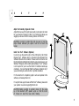
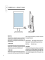
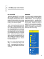
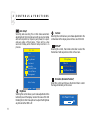
T A B L E
O F
C O N T E N T S
I. FCC Compliance Statement
II. Safety Instructions
III. Sicherheitsmaßnahmen und Wartung
1. Introduction
2. Setup
3. Controls & Functions
4. Timing Guide
5. Power Management
Appendix A: Specifications
Appendix B: Troubleshooting
Appendix C: TCO '95
1
2
3
4
6
9
15
16
17
18
21
II
F CC C O MP LI A NC E
S TAT E M E N T
Thi s equi pment has been tested and found to co mply w ith
the limits for a Class B digital device, pursua nt to Part 15 of
FCC Rules. These l imits are d esigned to provide reasonable
protection against radio frequency interference in a residential
install ation. This equipment generates, uses, and can radiate
ra di o freq uenc y energy. If no t i nsta l l ed a nd used i n
acc ordanc e with the i nstruc tions, it may cause interference
to radi o co mmunications. How ever, there is no guarantee
that interference will not oc cur in a particular instal lation. If
this equipment d oes cause interference to radi o or television
recep tion (this can b e determined by turning the equi pment
off and on), the user is enco uraged to try to correct the
interference b y one or more of the follo wing measures:
• Reori ent or relocate the recei ving antenna.
• Increase the separati on between the equipment and
receiver.
• Connect the equipment into an o utlet o n a circuit
different
from which the receiver i s connected to.
• Consul t the deal er or an experienced radio/
televi sion technician for help.
1
CAUTION
To comply with the limits for a FCC Class B computing device,
always use the shielded signal cord and shielded power cord
sup plied with this unit.
CAUTION TO THE USER
The Federa l Co mmunications Commission warns the user
tha t changes or mod ific atio ns to the uni t no t expressl y
approved by the party responsible for compliance could void
the user’s a uthority to operate the equipment.
NOTICE OF COMPLIANCE WITH CANADIAN INTERFERENCECAUSING EQUIPMENT REGULATIONS
DOC COMPLIANCE NOTICE
This d igital app aratus does not exceed the Cla ss B limits for
rad io no ise emissions from digital ap paratus set out in the
Radi o Interference Regula tions o f the Canadian Department
of Co mmunications.
DOC AVIS DE CONFORMATION
L e p resent a p p arei l numeri que n’emet p as d e b rui ts
rad io elec triq ues d epa ssa nt les l imi tes a pp li c ab l e aux
a pp a rei ls numeri q ues d e l a cl a ss B p rescri tes da n l e
Reglement sur l e brouil lage rad ioel ectriques ed icte par le
ministere des Communications du Ca nada.
III
S A F E T Y
I N S T R U C T I O N S
• Powe r
- LCD Monitor Rated : 12 V d c , 5.5A ma ximum.
- Use the type of power indi cated on the marking label.
• Adapte r
-Only use an adapter designed for the LCD monitor
(Ault MW116KA1249F51 or Delta AD P-70RB)
-IMPORTANT : Use o f another type of adap ter will result in
malfunction a nd /or da nger.
• Plugs
- D o no t remove any parts of the monitor’s three pronged
power plug.
- Di sconnect the pow er plug from the AC outlet when the
moni tor will not be used for an i ndefinite period of time.
• Power and e xtension cords
- Use the p roper pow er co rd w ith the c orrect pl ug type. If
the p ower sourc e is 120V AC, use a power co rd that has UL
and CSA approva ls. If the power source is a 240V AC supply
use the ta ndem (T blade) type attachment plug with a ground
cond uctor power cord that meets the resp ective Europ ean
country’s sa fety regulations, such as VDE for Germany.
- A c ertifi ed p ower supp ly cord not lighter than ord ina ry
po lyvinyl chlorid e flexib le co rd ac cordi ng to IE C 60227
(d esignatio n H05VV-F 3G 0.75mm2 or H 05VVH2-F23G 0.
75mm2 ) sho uld be used. Alternati ve a flexible co rd be of
synthetic rubber according to IEC60245 (designation H05RRF3G, 0.75mm2 ) shall be used.
- Do not overload w all outlets or power cords. Be sure that
the tota l o f a ll uni ts plugged into the wal l o utl et does not
exceed 7 amperes.
- Be sure tha t the total ampere ratings on all units pl ugged
into the extension cord does not exceed the rating o f the
cord.
- If the monitor power supply cord requires a connection to
the P C instead of the w all outlet, this equipment is to be used
with a UL appro ved computer which has a rec eptacle rate of
100-240V AC, 50/60H z, 1.5A (minimum).
- Do not place anything on the power c ord. Do not loc ate this
product where a person may walk or trip over the cord.
• Environme nt
- Place the monitor on a flat and leveled surface.
- Place the monitor in a well-ventilated area.
- Keep the monitor awa y from:
Rain or water
Exc essive heat, cold or humidify.
Areas exposed to di rect sunl ight.
Dusty surro undings.
E quipment that generates strong magnetic fil eds.
• Warning
1. Do not use in the p resence of fla mmable a nesthetics.
2. Do not obstruct the ventilating ho les.
3. Do not use if the product has been exp osed to li quids.
4. Do not use if the cable ha ve been frayed or da maged.
5. Only c onnect to the device which has SELV Circui try or
Medical approval.
2
IIII
S ICHER HEITSMAß NAHMEN UND WAR TUNG
• Den Monitor von der Netzspannung tre nnen, w enn de r Monitor langere
¨
Ze it nicht benutzt wird.
• Versuche n Sie nicht, die ruckseitige
Abdeckung zu e ntfe rne n, da
¨
hierdurch strom fuhrende
¨
Teile freigele gt werden und die Gefahr von
elektrische n Schla
¨ ge n beste ht. Die¨ ruckse itige Abdeckung da rf nur
von qualifizie rte m Wartungspersonal abgenomme n.
• Legen sie keine Gegenstande
a uf das Monitorge ha¨use, die in die
¨
Beluftungsschlitze
¨
fallen konnen oder diese Schlitze a bdecke n konnen,
so daß die entste hende Warm
¨ e nicht a usreichend abgefuhrt
¨ w erden
ka nn.
• Se tze n sie de n Monitor nicht Regen oder
¨ aßiger F euchtigke it
¨ uberm
aus, um die Ge fahr eines e lektrischen Schlage s oder e ine daue rhafte
Be schadigung
¨
des Ge ¨rates zu ve rme ide n.
• Den Monitor nicht in dire ktern Sonne nlicht ode r in de r Nahe
¨ von
Wa¨rme quellen, z. B. von Heizkorpern,
¨
a ufste lle n.
• Um e ine ¨Uberhitzung zu ve rm eiden ist siche rzuste lle n, da ß die
Be luftungsoffnunge
n im Monitorge ha
¨
¨
¨ use nicht verdeckt werde n.
• De n Monitor nicht F euchtigkeit oder Sta ub ausse tze n.
• De n Monitor von m agne tischen Gegensta nden w ie Lautspre chern,
Elektrom otoren, transformatore n usw. entfe rnt ha lte n.
3
• Bei de r Aufstellung des Monitors darauf achten, daß Netzbuchse leicht
zuga
¨ nglich sind.
• Ve rwe nde n Sie keine Flussigke ite n a uf Alkohol-oder Am moniakbasis
zur Re inigung de s ¨Gera tes. Fa lls erforderlich, wischen Sie das ¨Gerat
mit eine m leicht ngefe uchteten Tuch a b. Trenne n Sie den Monitor
vorher von der Netzspannung!
• We nde n Sie sich an einen Se rvice-Techniker, w enn der Monitor nicht
norma l funktioniert, obwohl Sie die Be dienungsanweisungen in diesem
Ha nbuch befolgt habe n.
1
I
N
T
R
O
D
U
C
T
I
O
N
General Inform ation
With incredible style, versatility and visual brilliance, the LCD
monito r dual-inp ut flat pa nel can turn the dream of a perfect
di spl ay into real ity. By inc orp ora ting a nal og and di gital
interfac es, the LCD moni tor p rovid es the utmo st in disp lay
performance and co mpa ti bi lity of to da y’s a na log vid eo
stand ards, whil e guaranteeing comp atibility for tomorrow’s
a dvanced d igital standa rd s. T hi s sleek ergo no mi ca ll y
designed TFT display provides flexible four-way adjustments
for o ptimum d esktop use, along with VESA® wal l-mounting
c ap a bi l iti es to pro vi d e a w i d e a rra y o f user o p ti o ns.
Furthermore, its portrait mo de pro vides maximum internet
brow si ng c onveni ence w ith c onsi dera bl y less scrol li ng
requi red. A maximum resolution of 1600 x 1200 combined
with b rilliant ima ges that more than exceed the expectations
of even the most discriminating users.
The LCD monitor makes a n ul tima te flat panel so luti on for
tho se who prefer more desktop w orking spac e, the highest
video performance and flexibility, due to its smaller footprint
and size coupling with crisp, sharp display image quality.
Features
• 20.1” TFT Liq uid Crysta l Display with anti- glare trea tment
• H igh brightness and contrast
• Sup er wide 170o viewing angle
• UXGA 1600x 1200 maximum reso lution
• UXGA 1600x 1200 o ptimum reso lution
• 8 bits per 1 sub- pixel of gra yscale
• Dua l Digital and Ana log Interfaces
• DVI (Digita l Visual Interfa ce) Standard inp ut connector
• Four- way ergo nomi c ad justment: ti lt, height, swivel a nd
pivot
• VE SA® standard wall/arm mount ready
• Portrait Display Pivot® software (optional)
• User-friendly control dial and P reVuTM On-Screen Display
• DDC2B Plug & Pl ay
• Optional stereo speakers
• TCO’95 compliant
We trul y beli eve yo u wi ll enj oy usi ng the L CD monitor.
Thank you for making our pro duct your c hoice.
4
1
I
N
T
R
O
D
U
C
T
I
O
N
Check List
Before operating this monitor, please make sure that all items
listed below are present i n your pac kage:
• The LCD monitor
• This user’s ma nual
• Warranty statement
• AC Pow er cord
• AC/DC adapter
• D-sub 15-pin signa l cable
• DVI Cable
5
Optional Items
These are optio nal items and can be ordered by conta cting
dealer d irectly.
• DVI graphic card
• Stereo spea kers
• VE SA® stand ard wall/arm mount kits
• Pivot Driver and Utilities So ftware
If any of the ab ove items are found missing or if you wi sh to
order the optional i tems, please c ontact your d ealer .
2
S
E
T
U
P
No too ls a re required to set up the LCD monito r. Simp ly
foll ow the i nstructi ons outl ined in the next few pa ges.
Connectors for the signal cables and po wer are located on
the back of the panel b ehind the cover door. Please refer to
the d iagram on this page for the connector c onfigura tion.
Connect Signal Cable (V GA)
Atta ch the VGA si gnal c able end, whi ch has the ferrite core
furthest aw ay from the plug, to the monitor and attach the
other end to the graphi cs ca rd ad apter on your c omputer.
Be c auti ous i n i nserting the c ab l e p rop erl y i nto b oth
connectors. If the cable does not seem to fit it may be facing
the wrong di recti on. Turn the cable over and try to ma tch
the sha pe of the co nnector with that of the graphics ad apter.
Connect Power Adapter and Cable
Connect the round shape p lug end of the AC/DC adapter to
the D C Power input connector of the LCD monitor. Co nnect
the female end of the po wer cab le to the A C po wer inp ut
receptacle on the AC/DC a dapter. Then, plug the male end
of the power cable into an AC o utlet.
Conne ct DVI Cable
Connect the D VI cable to the DVI connector of the monitor.
If the cable does not seem to fit, it may be faci ng the w rong
direction. Please turn the cable over and try it.ling.
CAUTION: When yo u d isco nnec t the c ord/cabl es, be
sure to hol d the c onnector and no t the c able itself.
6
2
S
E
T
U
P
Cable Management
The LCD mo nitor has built-in c able guides and cover to help
yo u organi ze a nd route the cab les neatly o n yo ur d esktop
space. The cable cover is located on the back of the monitor
stand and it is opened by gently pulling it off the stand. Under
the cover, the cab les c an be held in po sitio n by numerous
clips.
There are several ways to route the cabl es and you may use
any way you fi nd suitabl e for your situa tion. However, the
ro uting method il lustrated by the d ra wing o n the right is
recommended to give the best result in mo st situations both
aesthetically and functionally. Once the cables are in position,
gently snap the co ver bac k on to the stand.
Anti-Theft Security Lock Slot
T he L CD monito r is equip ped w ith a security lo ck slo t
compa tible to Kensington® sec urity lock type. The security
ca ble loc k ma y b e avail able thru your dea ler or it can be
purcha sed at most computer peripheral stores nea r you.
7
2
S
E
T
U
P
Adjust the Four-Way Ergonomic Stand
Adj ust the four-way (tilt, height, sw ivel and pi vot) ergono mic stand
for your ma ximum vi ewing co mfort. To minimize eye fati que, we
suggest you a llow a minimum viewing d istance of 18 inches.
CA UTION: In order to p rotect the LCD, b e sure to hold the
ed ge of bezel whenever you adj ust i t a nd do no t touc h the
screen.
T
Install the Pivot® Software (Optional)
In order to use the p ivo t func tion of the L CD monito r, the Portra it
Di spl ay P ivo t® softwa re, which is i ncl uded i n the Optional P iv ot
Software CD,needs to be insta lled. Plea se read the instruction text
file (\Pivot\Commo n\English.txt) in the CD, using any text viewer such
Wind ows® Notepad, before installi ng the so ftware. P ivot® so ftwa re
is not required for you to use the monitor i n traditiona l la ndsc ape
orientation. It i s recommended that this software is instal led onl y if
you are intending to use the monitor in po rtrait orientation.
Fo r the l atest l ist of compati ble graphi c c ards and up dates to the
softw are, visit www .portrait.com.
For any technical support issues with the Pivot® software, please send
your question via e-ma il: [email protected].
CAUTION: Before pi voting to portrait mode, til t the pa nel
up to the maximum (20o) upw ard a ngle so that the co rner
of it does not touch the base whil e rota ting.
8
3
C O N T R O L S
&
F U N C T I O N S
Up
Down
Control Dial
The Control Dia l is a mul ti-functio nal device located b ehind
the LED Indicator on the right side o f the front bezel . It has
three movements - rotate upward, rotate downward and press
inward as a button.
1. Power On/ Off
Press the Control D ial to power the unit on from the off stage
(the L ED is off). To turn the power off, press the Contro l Dial
and hold for a t least 1 second until the LED turns off.
2. OSD Control
While the monitor is on (green LED and image on the screen),
pressing on the Control Dial activates the OSD. While the OSD
9
menu i s a cti ve, use the three wa y mo vements of the Control
Dial to adjust the monitor.
Rotate Dwonward : Move Up/Right, Increase, Larger, More
Rotate Upward : Move Down/L eft, Decrea se, Smaller, Less
Button Press
: Execute, Do, Save
LED Indicator
This LED indica tor turns green when the power is switched ON
and the power cord is properly attached . It turns amber when
the monitor goes into a power saving mode ( Active Off). Please
refer to the Power Management section of this manual fo r more
information.
3
C O N T R O L S
&
F U N C T I O N S
PreVuTM On-Screen Display
The LCD moni to r features an PreVuTM On- Sc reen D ispl ay
(OSD ) menu w ith easi ly id entifi ab l e ic o ns designed to
make ad justing your monitor display settings a more userfri endl y proc ess. When highl i ghted, the i co n il lustra tes
the c ontrol function and b rief i nstruc tio n to a ssi st the user
in i dentifyi ng whi ch co ntrol needs a djustment.
The OSD menu is a ctivated by p ressi ng the Co ntro l Di al
inward a nd you can selec t a nd adj ust the function of yo ur
cho ice by rotating and clic king the Control Dial . T he main
menu d ispl a ys a li st of sub menu i co ns and the c urrent
vi deo input mode. Rotate the dia l to move the highl ights
to the c o ntrol yo u w ould li ke to ad j ust, then p ress the
Control Dial inward to selec t that control o r to activate that
func ti o n. D epend i ng o n the c o ntro l yo u sel ec ted, a
submenu o f the c ontrol with a status ba r w ill app ear. T he
status b ar i nd ic ates i n which d irec ti on, from the fac to ry
p reset, yo ur a dj ustments a re b ei ng mad e. Rota te the
Co ntrol Dia l to ad just the contro l.
W hen you ha ve fini shed maki ng the a d j ustments, the
setti ng i s saved a uto ma ti c a l ly b y exi ting the c o ntro l
func ti on. If you d o no t to uch the c ontro l d i al for 20
sec o nd s, the OSD i s a uto mati ca l ly exi ted sa vi ng your
current settings.
Menu De scriptions
The L CD moni tor is cap abl e o f a ccepting b oth di gita l a nd
anal og signal i np uts a nd therefore ha s two d ifferent sets
of OSD co ntrol functi ons. Beca use the d igita l signa li ng
a l wa ys gi ves o pti mum d isp l ay q ua l i ty w i tho ut muc h
ad justment, i t requires much l ess OSD functions than the
a na l o g i np ut mo d e. T ho se fu nc ti o ns tha t a re no t
avai lab le i n the digital input mod e are Auto Setup,Display,
Clo c k/pha se, d eno ted b y a stri c k (* ) i n the fo l lo w i ng
descriptions. If selected w hil e i n d igi tal i nput mode, you
wi ll enc ounter a “Not Avail abl e” message.
M E N U
Exit
Auto Setup
Brightness
Contrast
Display
Display Mode
Clock/Phase
Management
Analog
: Enter
: +/Normal Mode
10
3
C O N T R O L S
&
F U N C T I O N S
Auto Setup*
Sel ecti ng and exec uti ng thi s c o ntrol ma kes automa ti c
ad justments to the horizo nta l a nd vertic al si ze, ho riz ontal
and vertic al p ositio ns, freq uenc y and phase fo r a quic k
a nd ea sy setup o f the d i sp l a y. There w il l b e a few
sec o nds o f d ela y whi l e the A uto Setup func ti o n is i n
process.
M E N U
Exit
Auto Setup
Brightness
Contrast
Display
Display Mode
Clock/Phase
Management
Auto Setup
Normal Mode
Brightne ss
Selecting this control allows you to make adjustments to the
luminosity level of the display screen in the scale o f 0 to 100.
Rotating the Co ntro l Di al up/do wn to ad just the Bri ghtness
any time while the OSD is off.
11
1
1
Contrast
Selecting this control allows you to make adjustments to the
contra st level o f the disp lay screen in the sc ale of 0 to 100.
DISPLAY*
Sel ecti ng this control, then ro tate contral dia l to sel ect the
Horizontal or Vertic al position co ntrol on the screen.
Display
Exit
H.Position
V.Position
H-Position (Horizontal Position)*
Select this control and then use the Contro l Di al to center
the image horizonta lly on the screen.
H.Position
50
3
C O N T R O L S
&
F U N C T I O N S
V-Position (Vertical Position)*
Select this control and then use the Contro l Di al to center
the i mage vertically o n the sc reen.
Display mode
Selec t this c ontrol, then use the control dia l to sel ect:
Normal : Adj ust red, green, blue by user’s preference.
Color comp. : Red, green, blue by fixed ra tio.
Calibration : Calibra te moni tor setting by using external
device.
Display Mode
Exit
Normal
Color comp.
Calibration
USER : A djust the Red (R-Gain), G (G- Gain) and B (B- Ga in)
individually to get the grey matching personal preference.
Phase*
Sel ecting this contro l allo ws yo u to a djust the AD C(anal og/
digi tal conversion) sampli ng cloc k phase so that the sc reen
ima ge app ear c risp a nd fo cused. Normally, the Auto Tune
is sufficient to complete this task in the automatic way without
user intervention; the Phase control allow s you to a djust it
manual ly in more precise manner.
Clock / Phase
Exit
Clock
Phase
12
3
C O N T R O L S
&
F U N C T I O N S
Clock*
Selec ting this contro l a llo ws you to adj ust the frequenc y,
sampling rate of horizontal pixels, to equal the video source’s
va lue, thus mi nimizi ng the sc reen artifa cts of shimmeri ng
vertical lines.
Scaling
Selecting this c ontrol to c hoose a sc aling.
Full : E xtend so urce image to full screen.
1:1 : Display source image directly.
Scaling
Clock
50
Managem ent
Selecting this control, then use Control Dial to select Scaling,
OSD D isplay, La nguage, So urce or Recall.
Management
Exit
Full
1:1
OSD OSD D isplay
Selec ting this submenu al lows you to adjust various settings
of the OSD to make the display adjustment process an easier
task.
Exit
Scaling
OSD
OSD Display
Language
Source
Recall
13
OSD Display
Exit
H.Position
V.Position
3
C O N T R O L S
&
F U N C T I O N S
H.Position (OSD Horizontal Position)
Selec ting this control allows you to move the OSD menu
hori zontally on the sc reen.
V.Position (OSD Vertical Position)
Selec ting this control allows you to move the OSD menu
verti cally on the screen.
Language
Sel ecting thi s control, then rotate the Control D ial to sel ect
the language you want. Press the Control Dial to excute when
selected.
Language
English
Francais
Deutsch
Italiano
Espanol
Source
Sel ecti ng this c ontro l al lows you to select between Digi tal
DVI a nd Analo g RGB si ngal inp uts.
Source
Exit
VGA
DVI
Analog
Digital
Recall
Sel ecti ng thi s c o ntro l resto res a l l o f the OSD c ontro l
adjustments to the fac tory d efault setti ngs.
Recall
Yes
No
Ex it
Sel ecting this exits the OSD.
14
4
T
I
M
I
N
G
G
U
I
D
E
Definition
The LCD monitor is a dual input type LCD monitor that is capable
of ac cepting b oth the traditional analog RGB vid eo signal s and
the new digital DVI (Digital Visual Interface) signa ling. For digital
DVI input, the LCD monitor w ill sup port resolutions used in the
digital DVI standard up to 1600 x 1200. Due to its digital design
and the impl ementation of this new d igital standard interfa ce,
setting frequenc y mode is no t necessary for an user a nd it will
be handled auto matica lly between the mo nitor and the digi tal
graphic card adapter.
For anal og RGB inp ut, the LCD mo nitor operates at ho rizontal
frequencies b etween 30kHz and 92kH z, verti cal freq uenci es
between 50Hz and 85Hz. Because of its microprocessor-based
d esi gn, i t o ffers a uto - sync hro ni z ati o n a nd a uto- si z i ng
capabilities. This monitor offers 20 preprogrammed settings that
are listed in the table to the ri ght.
Mode
Name
VGA
VESA
These preset modes c over most of the common video modes
supp orted by p op ul ar gra phic s ad ap ters. H ow ever, ea ch
adapter’s implementation of these video modes may vary slightly
in timings. If yo u fi nd i t nec essa ry to ma ke minor d ispl ay
adjustments (frequency, phase and position), please refer to the
Chap ter 3 for instructions o n maki ng these adj ustments.
15
Note that the monitor is not limited to these preset facotry timing
mod es. In fact, because the mo nito r is mul ti-scanning, it can
accept any signa l within its specified frequenc y range. Due to
i ts A uto A dj ustment c ap ab il ity, the mo nitor sets up cl oc k
frequency, phase, position and contrast level automatically when
a new video mode is encoun tered.
Mac
Resolution
Frequency
H
V
H(kHz)
V(Hz)
720
400
31.5
70
640
480
31.5
60
640
480
37.9
72
640
480
37.5
75
640
480
43.3
85
800
600
35.1
56
800
600
37.9
60
800
600
48.1
72
800
600
46.9
75
800
600
53.7
85
1024
768
48.4
60
1024
768
56.5
70
1024
768
60.0
75
1024
768
68.7
85
1280
1024
64.0
60
1280
1024
80.0
75
1600
1200
75.0
60
640
480
35.0
67
832
624
49.7
75
1024
768
60.2
75
5
P O W E R
M A N A G E M E N T
Definition
The po wer management feature of the LCD monitor enables
the mo nito r to recognize Energy Sta r® video a da pter a nd
power down to less than 8 watts of power consumption. An
E nergy Star ® c o mp ati bl e vid eo a da p ter a chi eves the
si gnal i ng b y setti ng ho ri z o nta l, o r verti c a l , o r b o th
synchroni za ti o n si gna l s to inac tive. T he LCD mo ni to r
rec ogni z es a ll tw o typ es o f signa l s and enters i nto the
appropriate mode. In Active Off mode, the LCD monitor still
maintains a detecti on and is alwa ys read y for fa st reco very
when both synchroniza tion signals are active a gain.
LED Indicator (Power Management Active)
T he p ow er ma na gement fea ture of the LCD mo nitor i s
comprised of two stages: On (green) and Active Off (amber).
In the A ctive Off mod e, the high vo lta ge functio n of the
monito r shuts down while the low power d etection circuitry
remains active. This c ircuit allows the monitor to “wake up”
when the mouse i s mo ved or a key o n the keyb oa rd i s
pressed.
Power Mode
LED Color
Power
Consumption
On
Green
< 80W
Active Off
Amber
< 8W
16
A PP E N DI X
A:
Panel Size/Type
20.1" TFT Active Matrix LCD,
a nti- gla re and ha rd(2H) c oated
Display Size (h x v)
16.1” x 12” (408mm x 306mm)
Pixe l Pitch (h x v)
17
S P E C I F I CA TI ON S
0.255mm x 0.255mm
Powe r (AC/D C Adapter)
Input: 100~240VAC, 60/50Hz,
Output:12VDC
Plug & Play
VESA® DD C2B
Ope rating Tem perature
Ope rating H umidity
Operating Altitude
41oF to 95oF (5oC to 35oC)
20% to 80% (No Condensation)
10,000 ft.
Storage te mperature
Storage humidity
Storage Altitude
-4oF to 131oF (- 20oC to 55oC)
10% to 90% (No Condensation)
30,000 ft.
Optim um Resolution
UXGA 1600 x 1200
Maximum Resoluti
UXGA 1600 x 1200
Contrast Ratio
1000:1 (Typical)
Brightne ss
700 cd/m2 (Typi cal)
Gray Scale
8 bi ts per 1 sub -pixel
Vie wing Angle
+85o to -85o(Left/Right)
+85o to -85o(Up/D own)
Dim ensions (w x h x d)
17.8” x 18.4” x 9.9” - with the base
(453mm x 467mm x 251mm)
Digital Signal Input
DVI Connecter
Net Weight
24 lb s. (11 kg)
Analog Signal Input
0.7 Vpp/75 Ohm
Sep arate and Co mposite TTL level
H. Freq.:
30 ~ 92kHz
V. Freq.:
50 ~ 85Hz
(UXGA:50 ~ 60Hz)
Composite sync
Sync on Green (SOG)
Compliance
Power Consum ption
On:<80W
Active Off:<8w
Transportation temperature -4oF to 131oF (- 20oC to 55oC)
Transportation humidity
10% to 90% (No Condensati on)
Transportation Altitude
30,000 ft.
FCC-B, CSA(C-UL), UL , CE,
TUV/GS,TCO ’95,EPA Energy Star®
WARNING: Do no t disassemble thi s monitor. Contact your
dealer if needed.
Attenti on: A cc ord ing to fac to ry sp ec ifi ca tio ns, d uring the
precise manufacturing process of LCD panels, i nevitably there
will be some defective colo r pixels.
APPE NDI X
B:
TR OU BLESHOO TI NG
TH E FOLL OW ING QUESTIONS A ND A NSWE RS A RE
SOME OF THE MOST COMMON PROBLEMS RELATED
TO YOUR LCD MONITOR. ANY PROBLEMS RELATED TO
YOUR COMPUT ER CAN BE FOUND IN T HE COMP UTER
MANUFACTURER’S USER MANUAL
by mo ving the mouse o r a keystroke on the keyb oard.
It’s a lso po ssib le that input sel ection (di gital o r a nal og) is
di fferent than the ac tua l signal present. Press the Co ntrol
Dial and the monitor will attempt to detect which input signal
is active.
The monitor is switche d on , but the Power LED Indicator
is not lit and there is no display on the screen.
Ma ke sure all of the pow er connections are secure. If the
mo nitor is plugged into a surge protecto r, ma ke sure the
surge protector is switched on.
The display appears to be discolored or missing some
colors . What can I do to correct this?
Check your co nnector c ab le and grap hi c s ca rd a nd /o r
graphics ca rd driver.
Both the monitor and computer are switched on , and
the Power LED indicator is green and lit , but there is no
display on the screen.
Ad just the brightness c ontrol to the highest setting. If you
see a fai nt gra y colo r appearing on the screen, the moni tor
is functioning properl y but no t receiving proper signal from
the video card.
Both the monitor and computer are switched on , and
the Power LED indicator is lit with amber color , but
there is no display on the screen.
Check the signal cabl e connec tions at both the monito r and
computer and make sure they are secure. Also, the computer
may be in a power saving mode. Try to reactivate the system
This LCD monitor has two video input connectors ,
analog and digital. Why are there two and which one
should I use?
The traditional a nalo g D -sub 15- pin connector of the L CD
monitor allows you to connect this monitor to VGA graphics
ada pters whic h are widely used i n most computers tod ay.
The DVI connector provid es superb image q uali ty w ith its
pure digital signal ing. If the best co nsistent di splay qual ity
is req uired , i t is hi ghly reco mmend ed that the DVI i np ut
co upled wi th D VI d igi tal grap hic adap ter is used with this
monitor.
18
APPE NDI X
B:
TR OU BLESHOO TI NG
What is DVI ? What is DFP?
Digi tal Video Interface (DVI) and D igital Flat Panel (DFP) are
new industry standard digital display signaling protocol based
on Sil ic on Ima ge’s T MD S tec hnol ogy. D VI a nd D FP a re
differentiated b y different connectors each ha s adapted. The
LCD monitor DVI connector is c ompati ble to DFP by using
the o pti ona l a dap ter. For mo re information on DVI, visit
ww w.ddw g.org. For more info rmatio n on D FP, vi si t the
VESA® ’s w eb site, www.vesa.org.
How do I change the resolution the m onitor displays?
The resol ution displ ayed o n a mo nitor is co ntroll ed by the
video card display driver and operating system. The monitor
simply resp onds to the signal i t receives from the video card
and is not abl e to change the resolution on its own. Mo st
vi deo card manufac turers pro vi de so ftware drivers a nd
utilities that al low you to use different resoluti ons for different
applications. Please consult your video card manual or dealer
for mo re informa tion.
Why do the letters and icons look soft on the edges
when I change to resolutions othe r than the native/
optimum resolution of the panel?
Unlike traditio nal CRT mo nitors, a LCD monitor has a native
(physical ) reso lution which pixels are produced by cells in
fixed posi tions. When a resolutio n different than the native
resol uti o n i s c ho sen, the L CD moni to r uses va ri o us
interp olation methods to achieve the pseudo resolutio n. To
ac hieve the op timum vi ewing quality, c hoosing the nati ve
resolution of the panel, 1280 x 1024, is recommended.
How do I change the frequency or refre sh rate the
monitor uses? (Analog D-sub 15-pin Input)
The refresh rate is controlled by the video card. Mo st video
cards provide a software utility or hardware DIP switches that
allows you to c hange the frequency used for each resolution.
For L CD monitors, there is no b enefit to increase the refresh
rate because there i s no fli cker wi th this type of monitor. In
fact, 60Hz is the recommended refresh rate for LCD monitors.
Can I use this display with Linux , MacTMOS and other
ope rating syste ms?
Yes. If a DVI or DFP co nnection is not available, then use the
VGA inp ut. For some co mputers an a ppro pria te c able or
adapter may be required.
19
APPE NDI X
B:
TR OU BLESHOO TI NG
How do I change the frequency or refre sh rate the
monitor uses? (Digital DV I Input)
Due to its digita l desi gn and the implementation of the new
di gita l standa rd i nterfac e, the L CD moni tor supp orts fixed
frequency used in the DVI Standard up to 1280 x 1024. Unlike
tra di ti onal CRT monitors in whic h electro n beams are
co nsta ntl y sc anned a cro ss the screen, there is no need to
change the refresh ra te of the d igi ta l input L CD monitor
beca use sc reen fli cker is not a p ro blem fo r this typ e of
monitor. The LCD monitor also supports lower resolutions
(1024 x 768, 800 x 600, 640 x 480, etc.) by scaling these lower
resol ution mo des up to the 1280 x 1024 resolution req uired
by the monitor.
If you are unable to correct the problem using the
TROUBLESHOOTING section.
Ple ase re fer to the cover of this manual for any warranty
information or num ber to call about obtaining se rvice on
your LCD Monitor.
The scre en flashes during boot-up or resolution changes.
Whi le bo oting up or changi ng resolution, the graphic c ard
re- i ni tia l iz es its vi deo memo ry a nd this is so meti mes
observed as screen fl ashes. The effect of this pheno menon
varies fro m card to card and i t is not considerd a problem.
20
A P P E N D I X
C:
T
C
O
‘
9
5
Congra tula ti ons! Yo u ha ve just purc ha sed a T CO’95
approved and labelled produc t! Your choice has provided
yo u w ith a p rod uct devel oped fo r p rofessional use. Yo ur
purchase has also contributed to reducing the burden on the
envi ro nment a nd a l so , to the further d evelo p ment o f
environmentally adapted electronics p roducts.
Why do we have e nvironmentally labelled computers?
In many countries, environmental lab elling has bec ome
an estab lished method fo r encouraging the a daptati on of
goods and services to the environment. The main p roblem,
as fa r a s c omp uters and other el ectronics eq uip ment a re
concerned, i s tha t environmenta lly harmful substances are
used bo th in the p rod uc ts and duri ng the manufac turing.
Since i t has not been possible for the majo rity of elec tronics
equipment to be recycled in a satisfactory way, most of these
potentially damaging substances sooner or later enter Nature.
There are also other chara cteri stics of a computer, such
as energy c onsumptio n levels, tha t are importa nt from the
view points of both the w ork (internal ) and natural (external)
enviro nments. Since all metho ds of conventional electricity
genera tion have a negative effect on the environment (acidic
and c limate-influencing emissions, radioactive waste, etc.),
it is vital to conserve energy. Electronics equipment in offices
consume an enormous amount of energy since they are often
left running conti nuously.
21
What does labe lling involve?
This p ro duct meets the req ui rements fo r the TCO’95
scheme which provides for international and environmental
labell ing of perso nal computers. The la belling scheme was
d evelo p ed as a j oi nt effort b y the T CO (T he Swed ish
C o n f e d e r a ti o n o f P r o f e s s i o n a l E m p l o y e e s ) .
Na turskyd dsforeni ngen (T he Sw ed ish Soci ety for Na ture
Conservation ) and NUTEK (The National Board for Industrial
and Tec hnical Devel opment in Sw eden).
T he req ui rements c o ver a w id e ra nge o f i ssues:
environment, ergonomics, usab ility, emissi on of electri cal
and ma gnetic field s, energy c onsumption and electric al and
fire safety.
The environmental demands concern restrictions on the
p resenc e a nd use o f hea vy meta l s, b ro mi na ted a nd
chl orina ted flame reta rdants, CfCs (freons) and chl orina ted
solvents, among other things, The product must be prepared
fo r rec ycl ing and the ma nufac turer is ob liged to ha ve an
environmental plan which must be adhered to in each country
where the company implements its operational policy.
The energy req ui rements incl ud e a dema nd tha t the
computer and/or display, after a certain period of inac tivity,
shal l reduc e its p ower co nsumptio n to a lower l evel in one
or more stages. The length of time to reactivate the computer
shall be reasonable for the user.
La b el l ed pro duc ts must meet stri c t envi ro nmenta l
demands, for exa mple, in respect of the reduction of electric
and magnetic fiel ds, physical and visual ergo nomi cs a nd
good usa bility.
A P P E N D I X
C:
T
C
O
‘
9
5
On the ba ck p age of thi s fol der, you w il l fi nd a b ri ef
summary of the environmental requirements met by this
product. The complete environmental criteria document may
be ordered from:
TCO D evelopment Unit
S-114 94 Stoc kholm
Sweden
Fax: +46 8 782 92 07
Email (Internet): [email protected]
Current information regarding T CO’95 approved and
labelled products may also be obtained via the Internet,
using the add ress:
http ://www.tco-info.com/
TCO’95 is a co-o perative p roject between TCO (The Swedish
Co nfe d era ti o n o f P ro f essi o na l E m p l o y e es),
Natursky ddsforeninge n (T he Swedi sh Soc iety for Nature
Conservation) and NUTEK (The National Boa rd for Industrial
and Techni cal Development in Sweden).
Environm ental equirem ents
Brominated flame re tardants
Bromi nated fl ame retardants are p resent in printed ci rcuit
boards, cables, wires, casings and housings. In turn, they delay
the sprea d of fire. Up to thi rty perc ent of the p la stic i n a
computer casing c an co nsist of flame reta rdant sub stanc es.
These are related to another group of enviro nmental to xins,
P CBs, w hi c h are suspected to give ri se to simi la r ha rm,
i nc l ud i ng repro duc ti ve d ama ge in fi sheati ng bi rds and
mammals, due to the b io-a ccumulati ve1) p roc esses. Fla me
retardants have been found in human blood a nd researchers
fear that disturb ances in fo etus devel opment may occur.
TCO’95 demand requires that plastic components weighing
mo re tha n 25 gra ms must not c onta in o rganic al ly b ound
chlorine and bromine.
Lead2)
Lead can b e found in pi cture tubes, d isplay screens, sol ders
and c ap aci tors. Lea d damages the nervo us system a nd in
higher doses, causes l ead poiso ning.
TCO’95 requirement permits the inclusion of lead since no
replacement has yet been d eveloped.
22
A P P E N D I X
C:
T
C
O
‘
9
5
Cadm ium 2)
Ca dmium is p resent i n rechargeab le b atteri es a nd i n the
c ol o urgenerati ng la yers of certa i n c o mp uter d i spl a ys.
Ca dmium da mages the nervous system and is toxic i n hi gh
doses.
TCO’95 requirement states that batteries may not contain
more than 25 ppm (parts per million) of cadmium. The colourgenera ting layers of disp lay screens must not c onta in a ny
cadmium.
Mercury2)
Mercury is sometimes found in batteries, relays and switches.
Mercury da mages the nervous system and i s toxic in hi gh
doses.
TCO’95 requirement states that ba tteries may not co ntain
mo re tha n 25 p pm (pa rts per mi ll io n) o f merc ury. It al so
demands that no mercury is present in a ny of the electrical or
electro nics components concerned w ith the displa y unit.
CF Cs (fre ons)
CFCs (freo ns) are sometimes used for washing printed circuit
bo ards a nd i n the manufac turi ng o f exp anded fo am for
packaging. CFCs break down ozone and thereby damage the
ozone layer in the stratosphere, causing i ncreased rec eption
on E arth of ultra violet light w ith co nsequent increased risks
of skin cancer (malignant melanoma).
23
The relevant TCO’95 requirement: Neither CFCs nor HCFCs
ma y be used during the ma nufa cturing of the prod uct or i ts
packa ging.
Bio- a ccumula t ive is def ine d a s subst a nces which a ccumulat e
wit hin living orga nisms
2)
Le ad, C admium a nd Me rcury a re he avy met als which are B ioa ccumula t ive .
1)