1
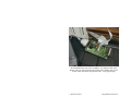
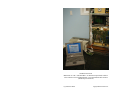
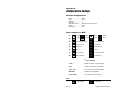
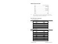
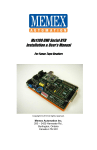
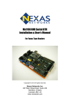
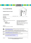
Mx1000 BTR
Installation & User’s Manual
For Fanuc Tape Readers
© 1994-2007
Memex Automation Inc.
777 Walkers Line,
Burlington, Ontario
Canada L7N 2G1
Phone: 905-635-3039 Fax: 905-631-9640
www.memex.ca
ii _ Mx1000 User’s Manual
© Memex Automation Inc. All Rights Reserved
Table of Contents
Introduction
V
About this manual..................................................
V
Behind the Tape Readers........................................
V
Chapter 1 – Installation Instructions
1
Component Checklist..............................................
1
Installing the Mx1000 BTR.....................................
2
Operating Your BTR...............................................
5
Chapter 2 – Reference
7
General Troubleshooting.........................................
7
Memex Customer Support & Service.....................
11
Glossary
13
Appendix A: Configuration & Settings
17
Software Configurations.........................................
17
Jumper Settings......................................................
17
Memex Serial Cable...............................................
18
Basic BTR Cable Configurations...........................
18
Appendix B: ASCII Table
Contents _ iii
19
© Memex Automation Inc.
Mx1000 BTR With Serial Cable (left DB25), 50 Conductor Fanuc Tape
Reader Cable (top right) and Facit 4070 Punch cable (middle). Note power
for unit comes from Fanuc Tape Reader cable – truly plug and play.
iv _ Mx1000 User’s Manual
© Copyright Memex Automation Inc.
Introduction
Thank you for your purchase of the Mx1000 BTR unit. Memex puts a great
deal of effort in the design, manufacture and testing of each unit we sell. We
are confident you will find the Mx1000 a useful addition to your shop floor
communications system.
About this Manual
This manual contains the specific steps necessary for the installation of your
Mx1000, as well as operating procedures and helpful hints for operating the
BTR. It is divided into two chapters and includes a table of contents, a
glossary and two appendices.
Chapter 1
Installation Instructions explains how to install your Mx1000
BTR interface board.
Chapter 2
Reference contains a troubleshooting section, and gives you
customer service and technical support information.
Appendix A Contains information for software configuration, jumper
settings and a Memex serial cable pin out chart.
Appendix B
Contains an ASCII chart for your reference.
Behind The Tape Reader
A BTR or Behind the Tape Reader, as it is commonly called, is an
electronic signal processor designed to emulate the signals of a paper Tape
Reader; thus providing an alternate method of data entry to an NC or CNC
control. That method, namely RS232 serial communication, is an
international standard form of electronic communication and data input that
is certainly faster and much more reliable than the conventional method of
punching tape or Manual Data Input (MDI).
Introduction _ v
Copyright © Memex Automation Inc.
Originally, the only one way that a G-Code operating program could be
entered into a machine tool was through MDI mode, which allowed the
program to be inputted using a keypad at the control. The MDI process was
fine for small programs, but it was time consuming and error prone for
longer programs. It took time to setup and to proof the MDI code before
operation could commence. Machine flexibility was low, since each new
program required time to input. With all the wasted time and lack of
flexibility, it was not very long before someone invented an alternate form
of control input, the paper Tape Reader.
The paper Tape Reader provided a faster, more reliable form of data input
to the industrial control. However, these Tape Readers were mechanical in
nature, and required regular maintenance and care to perform properly.
Tape Readers allowed data and programs that were punched out on a paper
tape to be read in by the control at a rate of approximately 300 to 400
characters per second. A few problems inherent in the Tape Reader were: its
limited ability to accept commands, its mechanical problems, its limited
ability to inform the operator of problems and status, its need to be kept
clean and its need for lubrication and other maintenance. It was commonly
suggested that a busy shop keep a spare reader in inventory in preparation
for the time when one broke down. In spite of the costs associated with
Tape Readers, the advantages of speedy input and reusable tapes were
welcome.
Unfortunately, the process of punching data tapes (whether they be paper,
Mylar or metal) was expensive, lengthy and necessitated storage concerns.
Because of the absolute nature of a punched tape, the process had to be
redone for every program revision. As well, proper communication had to
be kept up between the programmer and operator for the tape to be accurate
and kept up to date. Old tapes had to be filed or destroyed while the latest
version had to be marked as such and stored. Finally, the tape itself had to
be handled with care since it was prone to damage.
Later machine controls had a new mode of operation that allowed their Tape
Reader’s “endless” spool of tape to surmount memory constraints.
Originating on Numerical Controls (NC) that had no memory, Direct
Numeric Control (DNC) allowed execution of a program as it was read by
the reader. This “drip-feed” method meant that your program was limited in
size only by the length of tape that you used. This type of operation was
very much appreciated later on with the advent of Computerized Numeric
Controls (CNC).
vi _ Mx1000 User’s Manual
Copyright © Memex Automation Inc.
With true onboard memory the CNC had much greater capabilities and
inevitably programs got longer and the need for more memory grew. With
control memory being expensive and limited, DNC has remained the only
way some modern manufacturers can operate. With all this said, Tape
Readers are still commonplace on modern controls today; however, with
serial DNC capabilities, many shops use Tape Readers for backup purposes
only.
The modern equivalent to a Tape Reader is the BTR serial interface board,
which emulates paper Tape Readers. The Mx1000 is a microcontroller
based serial interface board, that allows serial communications with a
machine control for the purposes of loading programs into memory or
running DNC. BTR’s generally connect with a computer and permit a
programmer to send a completed, formatted program to the machine
control. The machine would then load the program from “Tape” to memory
or to execute the statements, block by block (in the case of DNC). Because
the Mx1000 BTR emulates the Tape Reader, the control really has no way
of knowing that the source of the program is from a serial port, instead of a
paper tape.
The Mx1000 BTR eliminates punching of tape, has no moving parts, can
handle transfer speeds that are 10 times that of a Tape Reader, uses the
programmed (source) file, is less expensive and does not require
maintenance. It’s no wonder that the BTR, in combination with DNC, has
become the most cost effective alternative to having on-board memory.
While the Memex BTR gives the modern machine control the ability to
receive programs from a PC, it has nothing to do with what is being sent to
the control. For this, one requires a terminal program or other serial transfer
utility (i.e.; multi-DNC). Your control is concerned with the data it receives
and the form in which it is sent. The BTR acts only as a gateway or port to
your control. Your terminal program has to be configured to send the data
as if it were a tape. This special program format is usually described in your
controls Operations Manual. Please consult this manual on how to configure
your programs for your control. The BTR is only interfacing with the Tape
Reader input on your control. Should you have any additional questions
concerning BTR’s in general, you are welcome to call us any time.
Introduction _ vii
Copyright © Memex Automation Inc.
Standard Connection:
Multi-DNC on a PC + Mx1000 BTR + 50 Pin Fanuc Tape Reader Cable to
CAT Connector on left of Masterboard + Facit 4070 Punch Cable on Door
(Honda 20 pin Connector)
viii _ Mx1000 User’s Manual
Copyright © Memex Automation Inc.
Chapter 1
Installation Instructions
For the Fanuc Tape Reader
Estimated time to complete: Under 45 minutes
Unpacking the Mx1000
Component Checklist
•
•
•
•
1 x Memex Mx1000 BTR............................ Supplied
1 x Fanuc Interface Cable............................ Supplied
1 x Screwdriver............................................ Supplied
1 x Manual................................................... Supplied
Optional Components
•
•
•
Serial Interface Cable (PC – BTR).............. Optional
SKU-5100 Fanuc punch interface cable…. Optional
Serial Transfer Software (Multi-DNC)........ Optional
Before you Proceed
Please read all instructions before proceeding. We recommended that you
first make a temporary installation, so that you familiarize yourself with the
components and orientation of the assembly before making the installation
permanent (i.e.; routing all cables through their appropriate channels).
Chapter 1: Installation Instructions _ 1
Copyright © Memex Automation Inc.
Installing the Mx1000 BTR
General
The Memex BTR installation is a straight forward, relatively easy to
complete procedure. All the hardware and accessories are provided for you.
All you need are some basic skills and hand tools. The installation requires
you to mount the Memex BTR on the inside of the Tape Reader door,
unplug the Tape Reader and connect the BTR. A ribbon cable that is
supplied allows the Reader to be reconnected via the BTR.
To install your Mx1000
1.
Prepare the site.
Ensure that the Tape Reader and control are working properly before
committing to this installation. When you are ready, turn OFF all
power to the control, machine and your computer system.
2.
Open the control door.
Locate the door on you machine control that has the Tape Reader
mounted in it. Open this door to gain access to the back of the Reader.
3.
Locate the 50 pin connector.
Located and identify the Tape Reader printed circuit board. The board
is located directly behind the reader and has two 50-pin IDC
connectors, labeled CNT1 and CNT2. The second (CNT2) has wires
going to the Tape Reader head. The Tape Reader cable (CNT1) has a
connector with a 50-conductor ribbon cable on it. The cable on this
connector goes to your CNC.
4.
Disconnect the Control.
Locate the 50-conductor cable that runs from the Tape Reader to the
Fanuc’s main control board. Disconnect this cable from the back of the
Tape Reader PCB (CNT1).
5.
Connect to the Control.
Holding the Memex BTR unit in front of you, orient it so that the 50pin connectors are on the upper half of the board, the DB-25 serial line
connector is at the bottom and the component side of the unit is facing
you. Now connect the cable which was plugged into CNT1 on the Tape
Reader into the left connector (Control A) of the BTR without twisting
the cable.
viii _ Mx1000 User’s Manual
Copyright © Memex Automation Inc.
6.
Mount the Mx1000 BTR.
Locate and magnetically mount your Memex BTR serial interface
board in a convenient spot on the back of the door.
7.
Option: Connect the Tape Reader.
Take the new 50-conductor ribbon cable and plug it into the connector
on the other side of the BTR labeled “TAPE READER A”. The red
wire and pin 1 should be aligned. Plug the other end of the cable into
the CNT1 connector on the Fanuc Tape Reader board. Again the red
wire on the ribbon cable should be aligned with pin 1 on the connector.
8.
Option: Fanuc punch cable.
Locate the punch port on your control. It is usually a blue, rectangular,
20 pin connector. Plug the Fanuc punch port interface adapter into this
port. Plug the other end (26-pin IDC) into the BTR connector labeled
“PUNCH IN”. Ensure that you have the proper alignment of pin 1. Be
sure to remove the jumper in the upper right corner of the BTR labeled
“PUNCH DISABLE”.
9.
Mark the Cables.
Mark the connectors and cables so that you are sure that they will be
reassembled properly during the final assembly process. Disassemble
the cables in order to route them neatly with the BTR unit attached at a
convenient location inside the control cabinet.
10. Connect to Computer.
Now connect a serial cable from the DB25F on the BTR unit to the
computer’s serial port. Route the extra cable in a neat and tidy fashion
and secure with tie-wraps. Refer to page 16 for cable diagrams.
11. Clean Up.
Complete the installation by tidying up the cables and making them
neat. Plug in the power cords for the computer. Check your work, and
turn on the power. Everything should come to life.
Caution
It is very important that the cables be installed properly and
with the correct orientation. If an end of one of the Reader
cables is plugged in upside down, sever damage will occur
to the Option Card, Tape Reader and the Control’s Master
Board.
Chapter 1: Installation Instructions _ 3
Copyright © Memex Automation Inc.
Summary of Mx1000 Safety Features:
You Mx1000 (and its new version the Mx1100) have several unique safety
features built-in. They include:
•
Low Power Reset Chip (if the power is less than 4.6 Volts DC, the
main micro-processor is held in reset state to protect against data
loss);
•
The use of keys on the cables to protect against improper insertion;
•
The use of self resetting fuses to guard against shorts and undue
maintenance costs in case of accidents;
•
The use of a back biases diode to protect against improper
powering of the unit from the screw-down terminals;
•
The ability for the unit to be remotely reset using a Control + C
command (hex 03 character) to prevent against residual data left
from a previous aborted download;
•
The inclusion of on-board power regulation allows for voltage
variance from 7-30 volts DC when needed.
4 _ Mx1000 User’s Manual
Copyright © Memex Automation Inc.
Operating your Mx1000 BTR
To use your new serial port, connect your cables and prepare your software.
Reset the BTR to ensure that no residual data is present in its buffer. This
can be done by simply pressing RESET on the Fanuc control or by
switching the Tape Reader (if connected) between AUTO and RELEASE
modes.
Start an upload to your control with your software, then go and load a
program at the control as you normally would from Tape.
Note:
Follow the procedures in your Operators Manual with one exception: Keep
the switch on your Tape Reader in the RELEASE position when you wish
to load programs through the BTR. The Mx1000 BTR senses the position of
the “AUTO / RELEASE” switch on the Tape Reader. Your control will
load the G-Code file as if it were a tape, although it will indeed load from
your computer through the BTR.
Helpful hints
Add a couple of Carriage Returns to the end of your file, thus ensuring that
the entire file is transmitted.
Chapter 1: Operating Your Mx1000 _ 5
Copyright © Memex Automation Inc.
6 _ Mx1000 User’s Manual
Copyright © Memex Automation Inc.
Chapter 2
Reference
This chapter contains troubleshooting hints and information about Memex
Technical Support and Service.
General Troubleshooting
The Mx1000 is designed to install easily and quickly. However, if you do
experience difficulty in the procedures, please check the following to isolate
the problem and resolve it quickly.
1.
Check that the PWR LED is on and bright on the BTR. It is
located* on the lower edge of the BTR just left of center.
If there is no power to the BTR, ensure that the cables from the Control
and from the Tape Reader are oriented properly and are well secured.
Also, check that the +5TR jumper is ON or that the +24TR jumper and
the REG ENBL jumper are ON. All three of those jumpers should NOT
be on at the same time. The proper setup of the jumpers will enable the
power to be supplied from the Tape Reader or the control. If the PWR
LED still does not come on, carefully find a source of power on the
control between 9 and 24VDC and wire it in to the “screw down”
terminal block in the lower left corner of the BTR. When you bring
power in through the terminal block, you will have to put jumpers on
the +24TR and REG ENBL. Make sure the +5TR jumper is removed in
this case.
Note:
*
All references made to objects located on the BTR will be made
with respect to the BTR being oriented horizontally so that you can read the
Memex Electronics name in the top left.
Chapter 2: Reference _ 7
Copyright © Memex Automation Inc.
2.
Check that the BTR is working properly.
When you turn on power to the control, the STATUS LED on the BTR
should blink. One blink indicates that the Mx1000 is in BTR Mode.
This means that it is ready to receive information through the serial port
and to send it to the control. Two blinks indicate that the BTR is in
TAPE Mode. This means that it is ready to pass information through
the BTR from the Tape Reader to the Control.
On some Readers, turning the Tape Reader on/off or switching the
Reader between Load and Release will switch the BTR between these
different modes.
3.
If the BTR “Locks Up”?
Look in the upper left corner of the BTR for the four pins labeled
RESET and LOAD. Of those four pins, the top two are the reset pins.
Touching the two RESET pins together while the power is on should
reset the BTR and make the STATUS light flash when you release
them. This action is the equivalent to pressing the reset button on a PC.
It is like a “cold boot”. You should not have to do this on a regular
basis but you may need to do so occasionally.
4.
Check the status message.
When the BTR is connected properly to a computer, a small message
should appear on the screen when the BTR has just been turned on or
reset. This message indicates the mode that the BTR is currently in.
5.
The Status light flashes but there is no status message reported
back to the computer.
First you have to be watching for the status message with a terminal
program or utility. Once you have loaded a program that receives
RS232 information on your computer, verify that you are using the
correct communication parameters and check that you are using the
correct COM port on the computer. Check that the BAUD RATE is
properly set and matches the baud rate on the BTR (check option
jumpers A1 and A2; see pg. 15) and that the STOP BITS are set for 1.
Make sure that the cable you are using is a straight through MODEM
cable and that it is properly connected (see page 16). Also verify that
your PC’s COM port is functioning properly.
8 _ Mx1000 User’s Manual
Copyright © Memex Automation Inc.
6.
The file you are sending to your control doesn’t wait for you to
press “Cycle Start”. You probably do not have the correct
“handshaking” set. Check that you are using either Hardware or
Software handshaking on your terminal software and that the
appropriate option is set on the BTR (jumper A3). If you are trying to
use Software handshaking, some terminal programs look at the XOFF
character (13 hex) with even parity (93 hex). Try setting option jumper
A4 to make the XOFF character a 93h.If you are trying to use
Hardware handshaking, make sure that you are using the proper cable.
You must have pins 4 and 5 connected properly between your terminal
and the BTR. If you are using a three conductor cable to communicate,
Hardware handshaking is not possible.
7.
Your control gives you an error just after pressing “Cycle Start”.
Try to remove either the CR (carriage return) characters or the LF (line
feed) characters from you program. Machine controls usually read ISO
or EIA code through a taper reader. As a result they may only accept
“pure” ISO or EIA code through the Tape Reader or BTR. These codes
typically do not contain any CR characters so your control may give an
error if it reads one.
8.
Your control gives you a Tape Vertical (TV) alarm. Tape Vertical
checking was a way that controls verified the accuracy of the program
code they read in through the Tape Reader. It is usually an option and
does not apply when you are using a BTR. Turn this option off.
9.
Your control gives you a Tape Horizontal (TH) alarm.
Tape Horizontal is equivalent to Even parity. Use even parity when you
are sending your programs from the terminal or PC (see also note 7).
10. If the Power LED comes on the BTR but the STATUS LED does
not. Check the supply voltage to the BTR. If you are using a 5VDC
supply and it is less than 4.7VDC, the BTR may actually be protecting
itself from under voltage. Find a better 5V supply or use the screw
down terminal in bottom, left corner and use a supply of 9-24V. Be
sure to set up the power jumpers correctly, in any case (see note 1).
11. Other machine errors:
Ensure that you have added in the proper tape codes at the beginning or
end of your program. Some machines require that you have a % sign as
the first and/or last character in your program. Check your control
manual for any termination characters that may be required.
Chapter 2: Reference _ 9
Copyright © Memex Automation Inc.
Memex
Technical Support & Service
Memex Automation provides toll-free technical support for the Mx1000
BTR. If you have a problem, be sure to review the troubleshooting section
of this manual prior to calling for technical support. If you cannot resolve a
problem after reading through the troubleshooting section, please contact
Memex Automation technical support at 1-905-529-1533.
Please note that Memex stands behind its product with a 3 year limited
normal use warrantee. This warrantee does not protect against lightening or
power surge damage, but experience has shown that even in these cases
only a small repair charge is ever necessary. Our goal is your 100%
satisfaction and years of reliable service.
If you have any other questions or concerns, need answers to technical
questions, or need information about Memex products and/or services
please contact your local product dealer, or contact Memex Automation
sales at the address below:
Memex Automation Inc.
777 Walkers Line,
Burlington, Ontario, Canada
L7N 2G1
Phone: 905-635-3039
Fax: 905-631-9640
http://www.memex.ca
Email: [email protected]
[email protected]
10 _ Mx1000 User’s Manual
Copyright © Memex Automation Inc.
Glossary
ANSI (American National Standards Institute) The official US agency
and voting representative for ISO. This institute develops information
exchange standards above 50 Mbps.
ASCII (American Standard Code for Informational Interchange) A seven
bit alphanumeric code used extensively in data communications. A parity
bit is often added to the seven-bit code for error detection.
ASR 33 An asynchronous serial interface standard that specifies the
electrical, functional, and mechanical interface specification between
communicating devices. Also known as “Current Loop”.
ASYNCHRONOUS TRANSMISSION The transmission of characters
separated by time intervals that vary in length, usually in accordance with
the key entries of a terminal operator. Start and stop bits are used to identify
(frame) the beginning and end of the asynchronously transmitted character.
BAUD RATE The rate at which a signal is changed or modulated. Baud
rate is directly related to the number of bits transmitted per second.
BTR (Behind the Tape Reader) An electronic input device used to
emulate a Tape Readers signals on a machine control. They usually convert
some form of serial communication to the parallel Tape Reader signals.
CNC (Computerized Numerical Control) An industrial computer that is
used to control the axis and movement of a machine. A CNC usually uses
programs coded with G-codes and M-codes.
CONTROL Refers to a Computerized Numerical Control (CNC).
CTS (Clear To Send) One of the control lines used in RS232
communication. Found on pin 4 or 5 on a DB25 and pin 4 or 8 on a DB9
depending on the type of device (DTE or DCE).
CURRENT LOOP A serial interface standard that has evolved from the
old electromechanical teletype which used current to activate its relays.
Typically 20ma or 60ma is turned on and off in accordance with the binary
serial data.
Chapter 2: Memex Customer Support & Service _ 11
Copyright © Memex Automation Inc.
DCE (Data Communication Equipment) Typically a modem or data set
used to interface a terminal or computer to the telephone lines.
DNC (Direct/Distributed Numeric Control) A means of communicating
or “Drip Feeding” a program to a CNC through a Tape Reader or serial
interface. The program code is acted upon immediately block by block as it
is read by the control.
DTE (Data Terminal Equipment) In data communications, it is an end
user or termination circuit, typically a terminal or computer.
ECHO A reflected signal. Information is sent back to the transmitter from
the receiver, often for verification purposes.
EIA (Electronic Industries Alliance) A United States organization of
manufacturers that establishes and recommends industrial standards. They
developed the EIA standard code used in early NC and CNC
communications. The standard allows for ODD parity and is countered with
ISO which is EVEN parity on the data bits.
FRAMING The procedure used to identify the beginning and end of a
group of data bits.
FRAMING ERROR This type of error occurs when a receiver looses
synchronism to the incoming data.
HANDSHAKING A process that regulates and controls the flow of data
between two devices.
HARDWARE HANDSHAKING Handshaking by use of the RTS and
CTS control lines on a RS232 serial interface.
ISO (International Standards Organization) One of the largest and most
widely recognized standards organizations in the world. Also, a form of
data format (encryption) similar to ASCII. It is a form of 7 bit ASCII with
even parity used largely on CNC’s.
LOCAL ECHO When a terminal is configured to internally route its
transmitted character around to its receiver section for display, a local echo
is said to be generated.
14 _ Mx1000 User’s Manual
Copyright © Memex Automation Inc.
MARK A logic 1.
MODEM A contraction of the words modulator/demodulator. The modem
converts a computer’s digital bit stream into an analog signal suitable for
the telephone lines and vice versa.
PAPER TAPE A media of program code storage. Holes were punched in
the paper tape to represent different program codes. These tapes were then
read through a Tape Reader to be loaded into CNC memory.
PARITY An error detection method whereby a single bit is added to a
group of bits to make the total number of 1 bits either even or odd
(depending on the type of parity; even or odd).
PARITY ERROR Indicates that the total number of 1 bits in a received
character does not agree with the type of parity expected.
RI (Ring Indicator) One of the control lines used by modems in RS232
communication. Found on pin 18 on a DB25 and pin 9 on a DB9 connector.
RS232-C An asynchronous serial interface standard that specifies the
electrical, functional, and mechanical interface specification between data
communication devices.
RTS (Request To Send) One of the control lines used in RS232
communication. Found on pin 4 or 5 on a DB25 and pin 4 or 8 on a DB9
connector (depends on whether port is for DCE or DTE).
RTS/CTS Hardware handshaking using the RTS and CTS control lines.
Rx Receive Data
SG Signal Ground.
START BIT The first bit used to frame an asynchronously transmitted
character. Its logic level is a 0 (space).
STOP BIT The last bit used to frame an asynchronously transmitted
character. Its logic level is a 1 (mark).
Glossary _ 15
Copyright © Memex Automation Inc.
SYNCHRONOUS TRANSMISSION High speed communication
whereby data characters are sent in direct succession to each other without
the use of Start and Stop bits.
TAPE READER Input device used on CNC Machines and other industrial
equipment. Used to “read” coded data on a punched paper tape. Older Tape
Readers were a mechanical device; today Tape Readers use optical devices
that sense light passing through the holes in the tape.
TERMINAL An input/output device used by an operator to communicate
with a host computer. It consists of a keyboard and a display to monitor
alphanumeric characters entered at the keyboard or received from a remote
device.
TIME-OUT ERROR This type of error occurs when a device fails to
respond to a message within a given period of time.
TTY Teletype Used in the Telex exchange. An electromechanical terminal
consisting of a keyboard, printer, paper Tape Reader and punch. Teletype is
a trade mark of the former Teletype Corp.
Tx Transmit Data.
XOFF (Transmit Off) A device control character (DC3 or $13 hex) used
to control the flow of data between two devices. XOFF is used as a
handshake with XON.
XON (Transmit On) A device control character (DC1 or $11 hex) used to
control the flow of data between two devices. XON is used as a handshake
with XOFF.
XON/XOFF Software handshaking using the XON and XOFF control
characters.
16 _ Mx1000 User’s Manual
Copyright © Memex Automation Inc.
Appendix A
Configuration & Settings
Software Configurations
Baud................................9600
Parity................................Even
Data Bits......................... 7
Stop Bits..........................1
ASCII Xfer Options..........With Strip the High Bit – ON
Duplex............................. FULL
Handshake...................... OFF
Option Jumpers on BTR
A1
= 1200
Baud
= 2400
Baud
= 4800
Baud
= 9600 *
Baud
A2
A3
CTS/RTS flow control
Xon/Xoff flow control *
A4
Xoff = $13 hex *
Xoff = $93 hex
A5
Single Xoff
*
Continuous Xoff
A6
Echo
*
No Echo
A7
No conversion *
ISO – EIA conversion
A8
Switch enabled
BTR mode only *
* Factory Defaults
+24TR
Enable 24V power from Tape Reader
+5TR
Enable 5V power from Tape Reader
+5V on 6,20
5V output on pins 6 and 60 of DB25F
REG ENBL
Enable 5V Power Regulator
Punch Disable
Use if Punch Port not connected
NOTE:
= NO Jumper
Glossary _ 17
= Jumper ON
Copyright © Memex Automation Inc.
RS232-C Serial Port Data
Pin 1..................................................Frame ground (shielding)
Pin 2.....................................................................Receive Data
Pin 3....................................................................Transmit Data
Pin 4....................................................................................CTS
Pin 5....................................................................................RTS
Pin 6.................................................................Loop Back to 20
Pin 7....................................................................Signal Ground
Pin 8..................................................................................GND
Pin 20.................................................................Loop back to 6
Pin 22...................................................................................5 V
Pin 23...................................................................................5 V
Pin 24................................................................................GND
Pin 25................................................................................GND
Note:
Memex has enabled Pin 18 as a power out line. A Raychem Polyswitch or jumper must be
present in position “F2” on the board. Power is limited to 300 mA by the RayChem Polyswitch.
Voltages vary depending on power input on screwdown terminals.
Basic BTR Cable Configurations
A – Software Handshaking Only
Computer
Mx1000 BTR
DB-25F
Tx – 2
Rx – 3
SG – 7
DB-25M
2 – Rx
3 – Tx
7 – SG
DB-9F
Tx – 3
Rx – 2
SG – 5
DB-25M
2 – Rx
3 – Tx
7 – SG
B - Hardware Handshaking
Computer
Mx1000 BTR
DB-25F
Tx – 2
Rx – 3
RTS – 4
CTS – 5
SG – 7
DB-25M
2 – Rx
3 – Tx
4 – CTS
5 – RTS
7 – SG
DB-9F
Tx – 3
Rx – 2
RTS – 7
CTS – 8
SG – 5
DB-25M
2 – Rx
3 – Tx
4 – CTS
5 – RTS
7 – SG
18 _ Mx1000 User’s Manual
Copyright © Memex Automation Inc.
Appendix B
ASCII Table
DEC
HEX
0
1
2
3
4
5
6
7
8
9
10
11
12
13
14
15
16
17
18
19
20
21
22
23
24
25
26
27
28
29
30
31
32
33
34
35
36
37
38
39
40
41
42
0
1
2
3
4
5
6
7
8
9
A
B
C
D
E
F
10
11
12
13
14
15
16
17
18
19
1A
1B
1C
1D
1E
1F
20
21
22
23
24
25
26
27
28
29
2A
SYM
NUL
SOH
STX
ETX
EOT
ENQ
ACK
BEL
BS
HT
LF
VT
FF
CR
SO
SI
DLE
DC1
DC2
DC3
DC4
NAK
SYN
ETB
CAN
EM
SUB
ESC
FS
GS
RS
US
SP
!
“
#
$
%
&
‘
(
)
*
Appendix B: ASCII Table _ 19
KEY
ctrl @
ctrl A
ctrl B
ctrl C
ctrl D
ctrl E
ctrl F
ctrl G
ctrl H
ctrl I
ctrl J
ctrl K
ctrl L
ctrl M
ctrl N
ctrl O
ctrl P
ctrl Q
ctrl R
ctrl S
ctrl T
ctrl U
ctrl V
ctrl W
ctrl X
ctrl Y
ctrl Z
ctrl [
ctrl \
ctrl ]
ctrl ^
ctrl _
DEC
HEX
43
44
45
46
47
48
49
50
51
52
53
54
55
56
57
58
59
60
61
62
63
64
65
66
67
68
69
70
71
72
73
74
75
76
77
78
79
80
81
82
83
84
85
2B
2C
2D
2E
2F
30
31
32
33
34
35
36
37
38
39
3A
3B
3C
3D
3E
3F
40
41
42
43
44
45
46
47
48
49
4A
4B
4C
4D
4E
4F
50
51
52
53
54
55
SYM
+
,
.
/
0
1
2
3
4
5
6
7
8
9
:
;
<
=
>
?
@
A
B
C
D
E
F
G
H
I
J
K
L
M
N
O
P
Q
R
S
T
U
DEC
HEX
SYM
86
87
88
89
90
91
92
93
94
95
96
97
98
99
100
101
102
103
104
105
106
107
108
109
110
111
112
113
114
115
116
117
118
119
120
121
122
123
124
125
126
127
56
57
58
59
5A
5B
5C
5D
5E
5F
60
61
62
63
64
65
66
67
68
69
6A
6B
6C
6D
6E
6F
70
71
72
73
74
75
76
77
78
79
7A
7B
7C
7D
7E
7F
V
W
X
Y
Z
[
\
]
^
_
`
a
b
c
d
e
f
g
h
i
j
k
l
m
n
o
p
q
r
s
t
u
v
w
x
y
z
{
|
}
~
DEL
Copyright © Memex Automation Inc.
Memex Automation Inc.
777 Walkers Line,
Burlington, Ontario Canada
L7N 2G1
Phone: 905-635-3039
Fax: 905-631-9640
http://www.memex.ca
Thank you for trusting Memex for your shop floor
networking needs.
20 _ Mx1000 User’s Manual
Copyright © Memex Automation Inc.