1
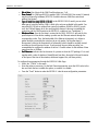
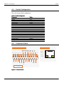
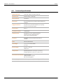
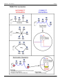
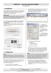
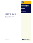
Serial Server
SSE232-LE
User´s Manual
Internet Enabling Solutions
www.exemys.com
SSE232-LE User’s Manual
Exemys
Exemys Products are in constant evolution to satisfy our customer needs.
For that reason, the specifications and capabilities are subject to change without prior notice.
Updated information can be found at www.exemys.com
Copyright © Exemys, 2006 All Rights Reserved.
Rev. 4
www.exemys.com
Rev. 4
Pageii
SSE232-LE User’s Manual
Exemys
Table of Contents
INTRODUCTION
1.1
1.1.1
1.1.2
1.2
5
The Manual ________________________________________________________
________________________________________________________ 5
Purpose of the Manual
Conventions, terms and acronyms
5
5
Product Description________________________________
Description___________________________________________________
___________________________________________________ 6
INSTALLATION
7
2.1
Power Connection ___________________________________________________
___________________________________________________ 7
2.2
Serial Connection ____________________________________________________
____________________________________________________ 7
2.2.1
2.2.2
2.3
2.3.1
RS-232 Connection
RS-485 and RS-422 Connection
7
8
Ethernet Connection __________________________________________________
__________________________________________________ 9
Connection through a Hub or Switch
9
CONFIGURATION AND OPERATION
3.1
3.1.1
3.1.2
3.1.3
3.1.4
3.1.5
3.2
3.2.1
3.2.2
3.2.3
3.2.4
3.2.5
3.2.6
3.2.7
3.2.8
3.3
3.3.1
3.3.2
3.3.3
Getting Started _____________________________________________________
_____________________________________________________ 10
IP Address Configuration
Access to configuration Web page.
TCP Configuration Command Console.
Serial Configuration Command Console
Configuration of Network Basic Parameters through the console
10
11
12
12
13
Operation________________________________
Operation _________________________________________________________
_________________________________________________________ 13
Introduction
SSE232-LE General Configuration
Configuration of serial ports
Inactivity timeout and Automatic Reset
Server Mode Channel Configuration
Client Mode Channel Configuration
Multidrop Mode
Supervision and Control Port.
14
15
17
19
20
21
22
23
UDP Transport Protocol________________________________
Protocol _______________________________________________
_______________________________________________ 24
Client Channel with UDP Protocol
Server Channel with UDP Protocol
Connection Between Two UDP Clients.
A. APPENDIX
www.exemys.com
10
25
25
26
27
A.1.
Device Locator Application ____________________________________________
____________________________________________ 27
A.2.
Indicator Leds Codes _________________________________________________
_________________________________________________ 29
Rev. 4
Pageiii
SSE232-LE User’s Manual
Exemys
A.3.
Default Configuration ________________________________________________
________________________________________________ 30
A.4.
Connectors Pinout __________________________________________________
__________________________________________________ 30
A.5.
Technical Specifications ______________________________________________
______________________________________________ 31
RS485 port connection ______________________________________________________ 32
Tables
Table 1 - Acronyms __________________________________________________________________________ 5
Table 2 - Conventions ________________________________________________________________________ 5
Table 3 - PASSWORD command _______________________________________________________________ 16
Table 4 - WEBCFG command _________________________________________________________________ 16
Table 5 - FACTRESET command _______________________________________________________________ 17
Table 6 - RESET command ___________________________________________________________________ 17
Table 7 - Configuration of serial ports___________________________________________________________ 19
Table 8 - ARESET command __________________________________________________________________ 20
Table 9 - Server Mode Channel Configuration_____________________________________________________ 21
Table 10 - Client Mode Channel Configuration ____________________________________________________ 22
Table 11 - STA and RST commands _____________________________________________________________ 24
Table 12 - PROTOCOL command_______________________________________________________________ 24
Table 13 - Default Configuration_______________________________________________________________ 30
Figures
Figure 1 - Detail of the Codification of the models __________________________________________________ 6
Figure 2 - Connectors ________________________________________________________________________ 7
Figure 3 - COM A to PC cable _________________________________________________________________ 8
Figure 4 - RS485 & RS422 Networks _____________________________________________________________ 8
Figure 5 - Scheme of connection without crossover network cable ______________________________________ 9
Figure 6 - Socket-Port Scheme ________________________________________________________________ 14
Figure 7 - Multidrop Mode: up to 8 clients _______________________________________________________ 23
Figure 8 - An SSE232-LE Client Broadcasts to all clients with IPSERV = Fixed IP ___________________________ 25
Figure 9 - Two SSE232-LE UDP, one client and one server ___________________________________________ 26
Figure 10 - Connection between two UDP clients __________________________________________________ 26
Figure 11 - Exemys Device Locator _____________________________________________________________ 27
Figure 12 - Indicator Leds Codes _______________________________________________________________ 29
Figure 14 - Connectors Pinout_________________________________________________________________ 30
www.exemys.com
Rev. 4
Pageiv
SSE232-LE User’s Manual
Exemys
Chapter 1
Chapter
Introduction
1.1 The Manual
1.1.1 Purpose of the Manual
The purpose of this manual is to provide instructions for the fast and simple installation and
operation of SSE232-LE over you Ethernet network.
The manual starts with the product description and then provides instructions for proper
installation of its hardware. Later on, it includes detailed information on SSE232-LE configuration
and operation.
1.1.2 Conventions,
Conventions, terms and acronyms
The acronyms used in this manual are listed in the following chart.
Table 1 - Acronyms
Acronym
ARP
bps
HTTP
IP
LAN
PC
UDP
TCP
DHCP
GND
Description
Address Resolution Protocol
Bits per second
HyperText Transfer Protocol
Internet Protocol
Local Area Network
Personal Computer
User Datagram Protocol
Transmission Control Protocol
Dynamic Host Configuration Protocol
Ground (Reference)
The conventions listed below are used in this manual.
Table 2 - Conventions
www.exemys.com
Convention
Description
A|B|C
n..m
(text)
aaa.bbb.ccc.ddd
A set of possible values for command parameters. You can type A, B or C.
A range of possible values. You can type any value in the range including n and m.
Any text, such as a server address.
An IP Address.
Rev. 4
Page5
SSE232-LE User’s Manual
Exemys
1.2 Product Description
SSE232-LE is a RS-232/485/422 converter to the Ethernet and vice versa. It allows access,
through the Ethernet, to equipment like alarm panels, data acquisitors, PLCs or any other device
with a serial interface.
SSE232-LE is the interface between the equipment with serial communication and the Ethernet
network, acting as a transparent converter . Figure 1 shows the codification used by each model
in detail.
SSE232- X Y I O - L E
RS-232 serial ports
RS-485/422 serial ports
Inputs
Outputs
Low End Applications
Figure 1 - Detail of the Codification of the models
www.exemys.com
Rev. 4
Page6
SSE232-LE User’s Manual
Exemys
Chapter 2
Chapter
Installation
2.1 Power Connection
SSE232-LE powering has no polarity and accepts an input voltage range of 9 to 30 VDC and
9 to 26 VAC.
2.2 Serial Connection
COM A is found in the DB25 DTE female connector, as shown in figure 3.
COM A can be configured as RS-232, RS-485 or RS-422.
Data Indicator Led
DB25 Connector COM A
(green)
Power Suply Jack
Ethernet Connector
Net Indicator Led
(yellow)
Figure 2 - Connectors
2.2.1 RSRS-232 Connection
If you need to connect COM A to a computer (or any DTE device) use the following cable.
www.exemys.com
Rev. 4
Page7
SSE232-LE User’s Manual
Exemys
PC
SSE232-LE
DB9 Female
DTE
DB25 Female
DCE
RxD
2
3
Rx
TxD
3
2
TX
GND
5
7
GND
RTS
7
4
RTS
CTS
8
5
CTS
DSR
6
6
DSR
DCD
1
8
DCD
DTR
4
20
DTR
Figure 3 - COM A to PC cable
2.2.2 RSRS-485 and RSRS-422 Connection
Use terminals TRX+ and TRX- to connect SSE232-LE to a RS485 network. And use terminals
TRX+, TRX-, RX+, RX- to connect SSE232-LE to a RS422 network.
RS-485
TR+ (14)
Data +
TR- (15)
Data -
SSE232-LE
Data -
Data +
Data -
Data +
RS-422
TR+ (14)
R+
TR- (15)
R-
R+ (21)
T+
R- (22)
T-
SSE232-LE
R-
R+
T-
T+
R-
R+
T-
T+
Figure 4 - RS485 & RS422 Networks
www.exemys.com
Rev. 4
Page8
SSE232-LE User’s Manual
Exemys
2.3 Ethernet Connection
RJ45 connector is used for the Ethernet connection. The Ethernet connection is essential for
SSE232-LE to operate. It can be connected to a Hub or Switch with an standard network cable.
2.3.1 Connection through a Hub or Switch
A UTP network cable is used to connect SSE232-LE to the Ethernet through a Hub or Switch.
RX + (1)
RX + (1)
RX - (2)
RX - (2)
TX + (3)
TX + (3)
TX - (6)
TX - (6)
SSE232-LE
HUB
Figure 5 - Scheme of connection without crossover network cable
www.exemys.com
Rev. 4
Page9
SSE232-LE User’s Manual
Exemys
Chapter 3
Chapter
Configuration and Operation
3.1 Getting Started
The first step consists in obtaining an IP address for SSE232-LE , by any of the following means:
Using the Device Locator application program (most recommended method).
Forcing an IP address entry to the ARP table.
Locally, by accessing the command console provided by SSE232-LE , at the serial
connection.
Once SSE232-LE has an IP address, the rest of the parameters can be configured:
By accessing the configuration web page of the equipment (most recommended
method).
Using the TCP command console.
Locally, by accessing the command console provided by SSE232-LE , at the serial
connection.
All configuration parameters are permanently stored in the memory and will be maintained even
in the event the equipment shuts down. Configuration parameters may be modified at any time
using any of the methods mentioned above.
3.1.1 IP Address Configuration
SSE232-LE default configuration is IP 0.0.0.0, so when turned on, it will search for a DHCP server.
SSE232-LE tries to negotiate an IP address with the DHCP server for a maximum period of 10
seconds. If the DHCP server fails to answer in that period, SSE232-LE will show an error code by
means of its indicator LEDs (see annex) and will try to establish connection with the DHCP server
60 seconds later. This process will be repeated indefinitely until a DHCP server assigns an IP
address to SSE232-LE or until the user assigns a static IP address. During the negotiation process,
SSE232-LE ’s yellow LED is steady on.
If you decide that SSE232-LE should have a static IP address (not assigned by a DHCP server) use
the Device Locator Software (Chapter 4.1) ot the serial console method (3.1.4)
www.exemys.com
Rev. 4
Page10
SSE232-LE User’s Manual
Exemys
There´s a third method to assing and IP address to the SSE232-LE , the ARP method.
If SSE232-LE receives, within 7 seconds after being turned on, an ICMP packet through a ping, it
will take the destination IP of this packet, provided it is different from that configured in SSE232LE .
To this effect, an entry can be added to the ARP table of a PC in the network.
The Windows ARP table must have at least one IP address other than its own in order for the ARP
command to work. Be sure the ARP table has at least one entry with the command:
arp –a
If the local machine is the only entry, send a ping to another device in the network.
Then add the entry to the ARP table of the PC, entering the following command:
arp -s 192.168.0.105 00-90-C2-XX-XX-XX
In Unix, the command to add an entry to the ARP table is the following:
arp -s 192.168.0.105 00:90:C2:XX:XX:XX
Send a ping to the IP address you added to the ARP table on the previous step, by entering the
following command:
ping 192.168.0.105 -t
The –t option will cause the ping to be continuously sent.
Turn SSE232-LE on. The equipment will only respond after a few seconds. Once SSE232-LE has
responded to the ping, you will have access to the equipment over the network.
3.1.2 Access to configuration Web page.
Once SSE232-LE has a valid IP address you may access the web page to configure the rest of the
parameters. You must use a web navigator that allows the use of Java Scripts.
1. If your web navigator is configured to search for a Proxy server, disable that option.
2. Type the SSE232-LE IP address in the “address” field of your navigator.
www.exemys.com
Rev. 4
Page11
SSE232-LE User’s Manual
Exemys
SSE232-LE will ask for the password to enter to the page. Type “admin” as user name and
then the password to enter.
3. You will see the SSE232-LE configuration web page. On the left side, you will find the
menu, and on the right side, you will find the configuration page.
3.1.3 TCP Configuration Command Console.
SSE232-LE supplies a command console to allow configuration by TCP in the port 998. The
machine will only administer one connection in this port, thus preventing the device to be
configured in simultaneous consoles.
To enter the console establish a telnet connection to port 998. In Windows, open a window of
commands and type the following command:
telnet 192.168.0.105 998
When the connection is established, SSE232-LE will show a welcome message to the
configuration command console.
SSE232-LE - Exemys (V2.0):
----------------------Password:
SSE232-LE will ask for a “Password”:
You will then have three opportunities to enter your password. After that, the console will be
blocked for 5 seconds before allowing you to re-enter your password.
3.1.4 Serial Configuration Command Console
Locally, you can access the serial port command console by connecting SSE232-LE to a RS-232
port of a PC. To such effect, you must have a serial terminal program (Windows HyperTerminal or
the like).
The communications program must be set as follows: 9600 bps, Parity: None, Data bits: 8, Stop
bits: 1, and flow control: none (9600,N,8,1).
(9600,N,8,1)
You can enter the configuration mode through the serial port:
Connect SSE232-LE to a PC and configure the terminal emulation program to
9600,N,8,1.
Turn on SSE232-LE . During the first 7 seconds SSE232-LE will wait for the CFG
command.
Type CFG and press ENTER. The SSE232-LE will display a welcome message to the
configuration command console.
SSE232-LE - Exemys (V2.0):
---------------------->_
www.exemys.com
Rev. 4
Page12
SSE232-LE User’s Manual
Exemys
3.1.5 Configuration of Network Basic Parameters through the console
Once you access the console, you can change the network configuration parameters with the
following commands: IP, NETMASK, and GATEWAY. If you want to change the SSE232-LE IP
address, Netmask and / or Gateway, you can enter the commands to modify these parameters.
But then you must enter the END command so the changes take effect. When the END command
is executed, SSE232-LE will detect that any of these three basic parameters has been changed
and the system will be restarted. If the console is run from a Telnet session, the communication
with the equipment will be interrupted. You must reopen the TCP session using the new IP
address.
To change the IP address, enter the following command:
>ip:192.168.0.110
Ok, IP Address
192.168.0.110
NOTICE, This parameter will be accepted upon execution of the END command.
At that moment, communication with the equipment will be interrupted.
If you are not sure, close communication without typing the END command.
>_
To change the netmask,
netmask enter the following command:
>netmask:255.255.255.0
Ok, Netmask
255.255.255.0
NOTICE, This parameter will be accepted upon execution of the END command.
At that moment, communication with the equipment will be interrupted.
If you are not sure, close communication without typing the END command.
>_
You can change the Gateway using the gateway command. Enter the following command:
>gateway:192.168.0.200
Ok, Gateway
192.168.0.200
NOTICE, This parameter will be accepted upon execution of the END command.
At that moment, communication with the equipment will be interrupted.
If you are not sure, close communication without typing the END command.
>_
Enter the END command for SSE232-LE to accept the network parameter changes. You will
lose communication with the equipment if the commands were entered from the TCP
console.
3.2 Operation
www.exemys.com
Rev. 4
Page13
SSE232-LE User’s Manual
Exemys
3.2.1 Introduction
In SSE232-LE, each COM (A, B, C o D) corresponds to a TCP socket. Thus, once communication
with any of these sockets is established, information will be transparently transferred from the
corresponding COM to the socket and vice versa.
Ethernet
TCP / IP Socket
COM
1000
A
Supervision and Control
Remote Configuration Console
Serial
999
998
Web Page
80
SSE232-LE
Figure 6 - SocketSocket-Port Scheme
The communication sockets that are in correspondence with the serial ports are flexible and
completely configurable. The SSE232-LE configured by the manufacturer so that TCP ports 1000,
1001, 1002 and 1003 are correspondent to COM A, B C y D respectively, but this may be changed
in each COM’s configuration.
As it can observed in figure 14, SSE232-LE has also 3 fixed TCP ports: Supervision and Control
(Port 999), Configuration Command Console (Port 998) and HTTP Server (Port 80).
Through the Supervision and Control Port (Port 999) you will be able to supervise the status of
each channel and administer SSE232-LE inputs/outputs.
SSE232-LE configuration command console is available on Port 998.
Each of the COM–socket TCP channels can function either in Client Mode or in Server Mode.
3.2.1.1 Server Mode
If a COM–socket channel is configured to function in server mode in a port configured by the user,
SSE232-LE will be on hold on that TCP port, waiting for a client to establish the connection (each
client will have to connect to the IP address and port of the server). Once the connection is
established, all the information received in the socket will be transmitted to the corresponding
serial port and vice-versa.
3.2.1.2 Client Mode
When operating in client mode, each COM-socket channel will have the IP address and port of the
server they have to connect to. Thus, that channel will try to establish communication with the
server every 10 seconds and, once established, the data received in the socket will be transmitted
by the corresponding serial port and vice versa.
www.exemys.com
Rev. 4
Page14
SSE232-LE User’s Manual
Exemys
3.2.1.3 DTR Client Mode
DTR client mode is similar to Client Mode but in this case the SSE232-LE will way the DTR signal
to go on before trying to stablish the connection. The SSE232-LE will finish the connection if the
DTR signal goes off.
3.2.2 SSE232SSE232-LE General Configuration
In this chapter, we will focus on the general aspects of SSE232-LE configuration.
3.2.2.1 How to obtain help from the command console.
To obtain help regarding a specific command, you can type the command followed by an
interrogation mark “?”. The console will display a help message, the syntax and a descriptive
text.
>port?
PORTx:...
Listen Port (1..65535)
>_
There also exist the HELP, HELPP y HELPS commands. The first two will display a complete
list of all available commands with their syntax and a descriptive text. The HELPS command lists
the commands for the Supervision and Control Port.
3.2.2.2 Configuration Password
Both the TCP configuration console and the web page are protected by a password. The device
administrator may assign access key for these resources, thus supplying safe access to SSE232-LE
configuration.
To change the password through the Web page:
Select “Advanced” from the menu, you will see the advanced configuration page.
Enter the Password in the “New Password” box, and type it again to confirm.
Click on the “Change Password” button, so the SSE232-LE may take the changes.
The administrator may change the password for the command console (both through TCP or,
locally, through the serial port) by using the PASSWORD command.
www.exemys.com
Rev. 4
Page15
SSE232-LE User’s Manual
Exemys
Table 3 - PASSWORD command
Command
Description
PASSWORD:(password)
Changes the password for remote configuration (TCP command console
or configuration Web Page). The password must not have more than 10
characters.
3.2.2.3 Enabling and Disabling Web Configuration
The administrator may enable or disable SSE232-LE configuration through the Web page. Once
disabled, the administrator will only be able to access the configuration remotely through the TCP
command console or, locally, by the serial command console. In both cases, the administrator will
be able to re-enable Web Configuration.
To enable or disable SSE232-LE Web Configuration page through the web page:
Select “Network” from the menu, you will see the Network configuration page.
Select the Web Configuration Enabling from the combo box.
Click on the “Send” button, so the SSE232-LE may take the changes.
From the command console (via TCP or serial), you may enable or disable the option of
configuration through the web page by executing the WEBCFG command.
Table 4 - WEBCFG command
Command
Description
WEBCFG:(E|D)
Enables or disables configuration through web page.
E = Enables
D = Disables
3.2.2.4 How
How to reset to manufacturer’s configuration
At any time, SSE232-LE administrator may reset to the original manufacturer’s configuration. This
option may be executed both through the Web page and through the command console.
To reset the original manufacturer’s configuration from the SSE232-LE Web page:
Select “Advanced” from the menu, you will see the advanced configuration page.
Click on the “Set SSE232-LE to Factory Defaults” button. A message will appear asking you
to confirm the action.
Select “Yes” if you want to reset SSE232-LE to Factory Default Configuration.
www.exemys.com
Rev. 4
Page16
SSE232-LE User’s Manual
Exemys
From the command control you may execute the FACTRESET command to reset the original
configuration. This command must be entered twice for the SSE232-LE to reset to its
predetermined configuration.
Table 5 - FACTRESET command
Command
Description
FACTRESET
Resets the original manufacturer’s configuration.
This command must be entered twice for the SSE232-LE to reset to the
manufacturer’s configuration.
3.2.2.5 SSE232SSE232-LE Reset
If necessary, SSE232-LE may be reset. If SSE232-LE is reset, all connections are closed and
SSE232-LE returns to its initial status.
To reset SSE232-LE through the Web page:
Select “Advanced” from the menu, you will see the advanced configuration page.
Click on the “Reset SSE232-LE ” button. A message will appear asking you to
confirm the action.
Select “Yes” if you want to reset SSE232-LE .
From the command console, you may reset SSE232-LE by executing the RESET command.
Table 6 - RESET command
Command
Description
RESET
Resets the SSE232-LE
This command must be entered twice for SSE232-LE to reset.
3.2.3 Configuration of serial ports
SSE232-LE ´s serial port may be configured according to your needs. The configuration parameters
of each COM are:
Baud Rate:
Rate Serial Port Rate of transference by bits per second. Possible values are: 300, 600,
1200, 2400, 4800, 9600, 14400, 19200, 28800, 33600, 38400 , 57600 y 115200.
Parity:
Parity Type of parity. Possible values are: NONE (without parity), EVEN (Even Parity) and
ODD (Odd parity).
www.exemys.com
Rev. 4
Page17
SSE232-LE User’s Manual
Exemys
Bits of data:
data Bits of data of the COM. Possible values are: 7 y 8.
Flow Control:
Control For COM type RS-232 in models 1083, 1C43 and 2043, flow control, if wanted,
may be configured by hardware (RTS/CTS). Possible values are: With flow control and
without flow control .
Type of Serial Port (only SSE232SSE232-1C431C43-LE):
LE) In the SSE232-1C43-LE model, you can select
what type of serial port will be COM A, which is the only one available in this model. You
may select RS-232 with or without flow control by hardware, RS-485 or RS-422. In each
case, the COM will always be A, the one thing that changes is the way to establish the
connection and the COM location in the SSE232-LE connectors (see “Installation”).
Window
Window of time:
time Once the first data is received in the COM, SSE232-LE will wait for this
specified period of time before sending a packet over the Ethernet network through the
corresponding socket. Thus, the band width of the Ethernet is improved, as it allows to
gather the bytes received by the serial port in an only packet. On the other hand, it
incorporates a delay in the transmission of information, which should be carefully treated
according to the serial protocol in use. If such protocol does not allow any delay, we
recommended to configure the window of time in 0. Possible values for the window of time
range from 0ms to 2000ms.
End Character:
Character Indicates the last character of a pattern to form the TCP package. If it is used
together with a value of window of time different from 0ms, the arrival of the end character
or the lapse of the time of the window, whichever happens first, will have priority.
To configure these parameters through the SSE232-LE Web Page:
Select the “COM A” in the menu
Enter the values as necessary. For the End Character parameter, enter the ASCII value in the
box and check the box to enable the option, or uncheck it to disable.
Press the “Send” button to make the SSE232-LE take the new configuration parameters.
www.exemys.com
Rev. 4
Page18
SSE232-LE User’s Manual
Exemys
You can also configure these parameters through the configuration command console. When
executing the commands that allow you to change these parameters, you must indicate the COM
you are referring to.
Table 7 - Configuration of
of serial ports
Command
Description
BAUDx:(Baud_rate)
Configures the rate of serial transference of the COM x in bps.
Baud_rate it may be 300, 600, 1200, 2400, 4800, 9600, 14400, 19200, 28800,
33600, 38400 o 115200.
PARITYx:(N|E|O)
Configures the parity of the COM x
N = NONE
E = EVEN
O = ODD
BITSx:(7|8)
Configures the amount of bits of data of the COM x.
COMTYPEx:(0..3)
Configures the Type of serial Port for the COM x.
0 = RS-232 without flow control
1 = RS-232 with flow control
2 = RS-485 (only SSE232-1C43-LE)
3 = RS-422 (only SSE232-1C43-LE)
WINDOWx:(0..2000)
Configures the window of time for the COM x. The rate of values is expressed in
milliseconds.
ENDCHARx:(0..255)
Configures the end character for the COM x. The value corresponds to the ASCII
value of the end character.
3.2.4 Inactivity timeout and Automatic Reset
Inactivity Timeout:
Timeout Both in Client Mode and in Server Mode, the maximum time allowed for
inactivity may be configured. Once this period of time lapses, SSE232-LE will consider the
connection terminated and will close it down. This option can be disabled so the connection will
not be closed even if no flow of information is detected. It is configured through the Inactivity
Timeout parameter independently for each channel. If this value is 0, the connection will not be
shut down due to the inactivity of that channel, i.e. the option is disabled.
Automatic Reset:
Reset In Server Mode, it may be the case that the connection of a client shuts down if
this client or another one tries to connect the server channel of the SSE232-LE that has the
automatic reset option enabled. SSE232-LE will abort the previous connection, allowing the new
client to connect. If the automatic reset is not enabled for that server channel, SSE232-LE will not
allow the connection of the new client and, in this case, the server may use the option of
inactivity timeout.
If the server channel has the automatic reset option enabled, and there is a connection
established with a client and another one tries to connect to the same server, the connection with
the previous client will be closed and the connection to the server of the new client will be
allowed.
www.exemys.com
Rev. 4
Page19
SSE232-LE User’s Manual
Exemys
Summing up:
Enabled Automatic Reset:
Reset If a new client tries to connect to an already opened link (with or
without the same client) the previous connection will be aborted to allow the connection of
the new client.
Disabled Automatic Reset:
Reset It will prevent a new client to connect if there already exists an
open link on the Server Port.
You may configure the Automatic Reset Option through the SSE232-LE Web Page:
Select “Network” from the menu, you will see the Network configuration page.
Select the Automatic Reset Enabling from the combo box.
Click on the “Send” button, so the SSE232-LE may take the changes.
You may configure the Automatic Reset option through the command console by executing the
ARESET command.
Table 8 - ARESET command
Command
Description
ARESET:(E|D)
Configures the Automatic Reset option for the channels in server mode
E = Enables
D = Disables
3.2.5 Server Mode Channel Configuration
The SSE232-LE channel configured in Server Mode will be on hold, waiting for a connection in a
specified port (configurable by the user).
If the connection is closed, the device will stay on hold, waiting for a new connection in that Port.
In Server Mode, the parameters for the channel must be configured as follows:
Mode:
Mode The mode for the channel must be Server Mode.
www.exemys.com
Rev. 4
Page20
SSE232-LE User’s Manual
Exemys
Port:
Port This identifies the TCP Port to which the clients that wish to send information must
connect. The information sent go through the corresponding serial COM and vice-versa.
Inactivity Timeout:
Timeout Time of inactivity of the link after which SSE232-LE will consider the
connection to the server terminated if no flow of information is detected.
To configure these parameters through the SSE232-LE Web Page:
Select the “COM A” link from the menu.
Enter the values as necessary.
Click on the “Send” button, so the SSE232-LE may take the changes.
You may use the configuration command console to change these parameters. In the commands
that allow to change these parameters you must indicate the COM you are referring to.
Table 9 - Server Mode Channel Configuration
Command
Description
MODEx:(S|C)
Configures the COM x mode. To select Server Mode, select S.
PORTx:(1..65535)
Port in which the client’s connection is waited.
INACTOUTx:(0..10000)
Maximum time of inactivity allowed to the connection corresponding to the COM x, after
which the connection is terminated and the device returns to client waiting mode. It is
expressed in minutes.
3.2.6 Client Mode Channel Configuration
In Client Mode, each channel tries to connect to a specified server (IP-Port) every 10 seconds.
Once the connection established, the information of the socket is transparently transmitted by the
corresponding COM and vice versa.
These are the configuration parameters for that channel in client mode:
Mode:
Mode The channel mode must be configured as Client.
www.exemys.com
Rev. 4
Page21
SSE232-LE User’s Manual
Exemys
Port:
Port Client channel Port.
Server IP:
IP IP address of the server to which the client’s channel will connect.
Server Port:
Port Server Port of the server to which the client’s channel will connect.
Inactivity Timeout:
Timeout Time of inactivity of the link, after which SSE232-LE will consider the
connection to the server terminated if no flow of information is detected.
To configure these parameters through the SSE232-LE Web Page:
Select the “COM A” link from the menu.
Enter the values as necessary.
Click on the “Send” button, so the SSE232-LE may take the changes.
You may use the configuration command console to change these parameters. In the commands
that allow to change these parameters you must indicate the COM you are referring to.
Table 10 - Client Mode
Mode Channel Configuration
Command
Description
MODEx:(S|C)
Configures the COM x mode. To select Client Mode, select C.
PORTx:(1..65535)
Client Port for the COM x.
IPSERVx:(aaa.bbb.ccc.ddd)
Server IP address to which the COM x will connect.
PORTSERVx:(1..65535)
Server Port to which the COM x will connect
INACTOUTx:(0..10000)
Maximum time of inactivity allowed to the connection corresponding to the COM x,
after which the connection is terminated and the devise re-attempts to connect to the
server. It is expressed in minutes.
3.2.7 Multidrop Mode
There exists the possibility to accept up to 8 clients simultaneously. SSE232-1XXX-LE maintains 8
server type connections on the same channel and transmits information to the serial port RS232/485/422 (RS-485 and RS-422 available in model
www.exemys.com
Rev. 4
Page22
SSE232-LE User’s Manual
Exemys
SSE232-1CXX-LE) that has been received by every TCP communication link. The information
received by the serial port is transmitted to all the clients of the Ethernet network.
RS-232 / 485 / 422
Servidor
SSE232-1XXX-LE
SSE232-LE
ETHERNET
SSE232-LE
Client 1
SSE232-LE
Client 2
SSE232-LE
Client 3
…
SSE232-LE
Client 8
Figure 7 - Multidrop
Multidrop Mode: up to 8 clients
3.2.8 Supervision and Control Port.
SSE232-LE incorporates the possibility to administer digital inputs/outputs and to supervise the
status of the connection sockets linked to every channel by simple commands.
The Supervision and Control Port works through a TCP connection in the port 999. Each command
must end with the CR character (ASCII 13).
The system will answer if each command has been successfully executed of not.
3.2.8.1 Supervision of Connections Commands
You may supervise the connections by executing the STA and RST commands..
The STA command will allow you to know the status of the connection of a channel on the
Ethernet side by answering ‘1’ (Connected) or ‘0’ (Disconnected).
The RST command allows to reset the socket of a specified channel. If your command is related
to a socket of a channel that is not available on that model, the answer will be “error”.
www.exemys.com
Rev. 4
Page23
SSE232-LE User’s Manual
Exemys
Table 11 - STA and RST commands
Command
Description
Answer
STA<CR>
Shows the connection status of the sockets of
all the channels available (according to the
model)
STA,wxyz<CR>
w, x, y, z: they may be ‘1’ o ‘0’
1 = Connected
0 = Disconnected
RST:x<CR>
Resets the socket of channel x.
The channel can be:
A = COM A
B = COM B
C = COM C
D = COM D
Depends on the amount of available channels
in the SSE232-LE model
RST:x,OK<CR>
Channel x has been successfully reset
RST:x,ERROR<CR>
The channel x has not been successfully
reset or the channel is not available in
this model.
3.3 UDP Transport Protocol
You may select the transport protocol for the Ethernet interface. Possible protocols are: TCP and
UDP.
UDP
The selection of the transport protocol affects all SSE232-LE channels. Thus, if you select the TCP
protocol, all the channels will use this protocol. And the same applies to the UDP protocol.
To change the protocol through the SSE232-LE configuration Web Page:
Select “Network” from the menu, you will see the Network configuration page.
Select the Transport Protocol from the combo box.
Click on the “Send” button, so the SSE232-LE may take the changes.
You may also change the protocol by executing the PROTOCOL command through the command
console.
Table 12 - PROTOCOL command
www.exemys.com
Command
Description
PROTOCOL:(T|U)
Configures the network protocol for all SSE232-LE channels.
T = TCP
U = UDP
Rev. 4
Page24
SSE232-LE User’s Manual
Exemys
3.3.1 Client Channel with UDP Protocol
For a channel in Client Mode, you must configure the IP address and Port of the server to which it
will connect. If you use an UDP Transport Protocol, that channel will transmit to that IP-Port the
information received by the serial and vice versa.
If the IP server address of that channel coincides with the broadcast address (IPSERV =
255.255.255.255), SSE232-LE will transmit to an UDP broadcast all the information received by
the serial. The serial will transmit whatever is received from the Ethernet side, no matter if the
information was received from a broadcast or from a specified IP address.
IP= 192.168.0.106
UDP Client Channel
IPSERV= 192.168.0.105
ETHERNET
IP= 192.168.0.105
IP= 192.168.0.107
UDP Client Channel
IPSERV= 192.168.0.105
UDP Client Channel
IPSERV= 255.255.255.255
IP= 192.168.0.108
UDP Client Channel
IPSERV= 192.168.0.105
Figure 8 - An SSE232SSE232-LE Client
Client Broadcasts to all clients with IPSERV = Fixed IP
3.3.2 Server Channel with UDP Protocol
For a channel in Server Mode, you must only configure that channel’s Port. When the transport
protocol is UDP, the server channel will be “linked” to the first IP address plus Port that sends a
packet.
The Inactivity Timeout parameter must also be configured, and it will work similarly as in TCP
mode. It will terminate the link with a specified IP address (the first to have sent a packet) once
the predetermined time lapses, thus allowing another IP address to establish communication with
the UDP server channel.
www.exemys.com
Rev. 4
Page25
SSE232-LE User’s Manual
Exemys
UDP
Client
UDP
Server
ETHERNET
Data ( lost )
SSE232-LE
SSE232-LE
RS-232
(1) Without any established connection any data is lost
UDP
Client
UDP
Server
ETHERNET
RS-232
SSE232-LE
SSE232-LE
First Datagram
(2) The client sends the first Datagram to establish connection
UDP
Client
UDP
Server
ETHERNET
RS-232
Data
SSE232-LE
Data
SSE232-LE
(3) Once connection is established all data is transmitted
Figure 9 - Two SSE232SSE232-LE UDP, one client and one server
When two SSE232-LE connect through an UDP Transport Protocol, one of them in Client Mode
and the other in Server Mode, the SSE232-LE in Server mode will not send the information
received by the serial to the Client’s IP unless the client has previously sent a packet to establish
communication. In other words, the SSE232-LE Server will have to receive a UDP packet from the
client to be linked to that IP. After that, all the information received by the serial port will be
transmitted to the client’s IP.
If the client fails to send a packet to the server, the server will not be able to establish a link and
the information received by the corresponding serial will be lost.
3.3.3 Connection Between Two UDP Clients.
The UDP mode, as different from TCP mode, allows communication between two devices
configured on Client Mode. This mode shows an advantage over client-server topology, since
connection can be established in both ways, without regard of which of the serial devices sends
the information first.
In this case, both devices must be configured in Client Mode and the IPSERV and PORTSERV of
the other device must be also configured.
1001
1000
ETHERNET
RS-232 / 485 / 422
RS-232 / 485 / 422
SSE232-LE
SSE232-LE
IP= 192.168.0.105
IP= 192.168.0.106
UDP Client Channel
IPSERV= 192.168.0.106
PORTSERV= 1000
UDP Client Channel
IPSERV= 192.168.0.105
PORTSERV= 1001
Figure 10 - Connection between two UDP clients
www.exemys.com
Rev. 4
Page26
SSE232-LE User’s Manual
Exemys
Appendix A
Appendix
A.Appendix
A.1.
Device Locator Application
The Exemys Device Locator Application Program is intended to use for the basic configuration of
any Exemys device over your ethernet network. It allows to search, identify and configure the
basic network parameters.
This simple application program is distributed with any Exemys product in the accompanying CD.
You can also download the latest version of this program from the Exemys Web Site
(www.exemys.com).
The Device Locator application must be running from any PC within the network where the
Exemys devices to configure are installed.
Figure 11 - Exemys Device Locator
When the Device Locator is run for the first time it will search any Exemys device within the
network. If there is an Exemys device in the network it will be shown in Device Locator Grid:
Device: Device name, such as SSE232-LE or KIBe.
Version: Firmware version it is running in that device.
MAC Address: Hardware Ethernet Address of the device.
IP: IP Address configured in the device
Netmask: Subnet mask configured in the device
Gateway: Gateway IP Address configured in the device.
www.exemys.com
Rev. 4
Page27
SSE232-LE User’s Manual
Exemys
DHCP Lease: if “Yes”, then the device network parameters where obtained from a DHCP
server.
It is not necessary for the device to be properly configured. If the device is correctly connected
and working, it will be found by the Device Locator Application
Application Program.
To refresh the grid, click on the “Query Network” button. This action will make the device Locator
to search any Exemys device in the network again.
You can change any of these basic network parameters within the Device Locator program.
To configure any Exemys device founded by the Device Locator:
Select the device in the grid and click on the
“Properties” button, or open the “Actions”
menu and select the “Properties” command.
You will see the Properties dialog box.
All Exemys devices provides a Remote
Configuration Password. This password is used
for the Web configuration page and remote
command Console in the device. Enter this
password in the “Enter current password” box
if the device has a configured password.
You can type an IP Address, Netmask and
Gateway IP Address or you can click on the
“Use DHCP” check box to make the device
search a DHCP Server.
Click on the “Ok” button so the Device Locator
sends this information to the device.
If the password is not correct, the Device Locator will show a “Error
Error Response from MAC
Address 0000-0B0B-FAFA-XXXX-XXXX-XX”.
XX The device will not respond any message send by the Device
Locator software within the first 5 seconds after an incorrect password configuration attempt.
This is to avoid any brute force method to change the network parameters of the device.
If the device does not respond, the Device Locator will show a “No
No Response from Device”
Device
message. Make sure the device is turned on and connected to the ethernet network.
The Exemys device will reset so the changes in the configuration take effect.
Click on the “Close” button to close the Properties dialog box.
After a few seconds the device being reset will answer again to the requests of the Device
Locator software. Click on the “Query network” button to refresh the grid and make sure the
parameters were changed.
www.exemys.com
Rev. 4
Page28
SSE232-LE User’s Manual
A.2.
Exemys
Indicator Leds Codes
SSE232-LE features two indicator LEDs: green and yellow.
The Yellow and it shows the general working order of the equipment.
The green led indicates data incoming status.
Figure 12 - Indicator Leds Codes
Yellow Led
Green Led
Description
It flashes alternately with Green Led
It flashes alternately with the Yellow
Led
Critical failure.
It is steady on
SSE232-LE is searching for a DHCP server on the
network.
It is ½ second on and ½ second off.
SSE232-LE is waiting for an IP address
configuration ping or the CFG command to be
entered.
It blinks like a beacon, 90% of a
second off and the remaining 10%
on.
SSE232-LE has an IP address and a carrier (link)
on the connection. This is the normal operation
status.
It is 90% of a second on and the
remaining 10% off
It has no IP address and it could not find a DHCP
server. It will search the DHCP server at 60second intervals.
It blinks very fast.
Absence of carrier on the link.
It is steady on and it turns off for
shorts periods of time
www.exemys.com
Rev. 4
SSE232-LE has detected Data in one of the
connections
Page29
SSE232-LE User’s Manual
A.3.
Exemys
Default Configuration
This is the factory default configuration.
Table 13 - Default
Default Configuration
Parameter
Value
IP
Netmask
Gateway
Protocol
Automatic Reset
Web Configuration
Digital Input Report
Remote Configuration Password
Baud Rate
Parity
Data Bits
End char
Window of time
Mode
Listen Port (Server Mode)
Server IP Address (Client Mode)
IP Port Server Number (Client Mode)
Inactivity Timeout
COM Type
0.0.0.0 (DHCP)
0.0.0.0
0.0.0.0
TCP
Enabled
Enabled
Disabled
None
9600
None
8 bits
Disabled
Disabled (0ms)
Server
1000
192.168.0.99
1000
Disabled
Depends on the SSE232-LE model
A.4.
Connectors Pinout
DB25 Female Connector DCE
Ethernet Connector
DCD GND DSR CTS RTS Rx
(out)
Tx
NC NC NC NC NC
13
25
12
24
11
10
23
NC
9
22
Rx + (1)
(out) (out) (in) (out) (in)
8
21
7
20 19
NC NC NC
6
18
5
4
17
3
16
2
15
1
14
1
8
Rx - (2)
Tx + (3)
Tx - (6)
NC NC NC NC
R-
R+ DTR
TR-
TR+
(in)
NC = NO CONNECT
Figure 13 - Connectors Pinout
www.exemys.com
Rev. 4
Page30
SSE232-LE User’s Manual
A.5.
Exemys
Technical Specifications
• Network protocols:
TCP/IP, UDP, TELNET, HTTP, DHCP, ICMP, ARP.
• Network port:
Ethernet 10-Base T, RJ45 plug
• Serial protocol:
Transparent.
• Serial port:
RS-232, RS-485, RS-422, all tied to a DB25 female (DCE)
Connector.
• Supported devices:
Any device with a serial RS232/485/422 port requiring
an access to an Ethernet network.
• Flow control:
RTS/CTS.
• Connection control:
DSR/DTR/DCD.
• Administration:
Embedded HTTP server, password protected.
Telnet-like console, password protected.
Serial console, password protected.
• Firmware:
Upgradable, by using a programming cable (not
included).
• Leds:
Status led, data led/link.
• Size/Weight:
1 x 2.75 x 3.15 inches (HxWxL)
0.772 Lbs.
• Power Supply:
9-26 VAC, 9-30 VAC
200mA max
• Temperature:
Operating temperature: 23 to 149 ºF (-5 to 65ºC).
Storage temperature: -40 to 167 ºF (-40 to 70 ºC).
• Accessories not included: Programming cable.
COM port redirector software.
DIN rail mounting plug-in.
• Warranty/support:
www.exemys.com
Limited one year warranty. Technical Support included.
Rev. 4
Page31
SSE232-LE User’s Manual
www.exemys.com
Exemys
Rev. 4
Page32