1
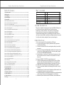
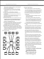
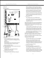
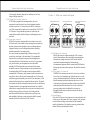
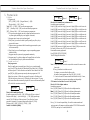
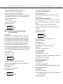
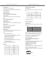
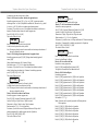
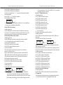
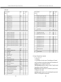
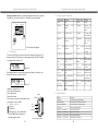
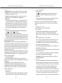
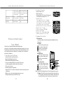
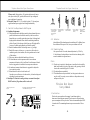
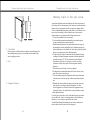
LCD Intelligent Alarm
System
User's Manual
Mar, 2007 Publish
Please read this manual carefully before you operate
Telephone Network Intelligent Alarm System
Table Of Contents
Telephone Network Intelligent Alarm System
What's included
1.System Introduction ------------------- --------------------------------------------------------------(2)
2.Main Functions -------------------- -------------------------------------------------------------------(2)
3.System Diagram --------------------------------------------------------------------------------------(3)
4.System Installation --------------------------------------------------------------------------------- -(4)
5.Program Guide ---------- ----------------------------------------------------------------------------- (9)
Directive 00: Set/modify installer code --------------------------------------------------------------(9)
Directive 01-09: Set/modify user code/master code ------------------------------------------------ (10)
Directive 10-14: Set telephone number -------------------------------------------------------------- -(10)
Directive 15-19: Set zone list to dial corresponding telephone number when alarming ------- (11)
Directive 20: Set dialing mode------------------------------------------------------------------------- (12)
Directive 21: Set telephone communication protocol ----------------------------------------------- (12)
Directive 22: Set dialing times--------------------------------------------------------------------------(12)
Directive 23: Set ringing times- ------------------------------------------------------------------------(12)
Directive 24: Set ADEMCO accounts------------------------------------------------------------------(12)
Directive 25: Set KS 6+2 accounts---------------------------------------------------------------------(12)
Directive 26: Set wireless siren -------------------------------------------------------------------------(12)
Directive 27: Open/Close phone line cut off report function --------------------------------------(13)
Directive 28: Set timing communication zone list --------------------------------------------------- (13)
Directive 30: Set zone attribute -------------------------------------------------------------------------(13)
Directive 31: Set wired zone respond speed ---------------------------------------------------------- (14)
Directive 32: Set circuit type for wired zone - --------------------------- ------------- ---------------(14)
Directive 33: Set Alarm delay/Arm delay for appointed zones. -------------------- ---------------(14)
Directive 34: Set inner siren alarm duration for appointed zones- ---------------------- ----------(15)
Directive 35: Set linkage alarm output duration for appointed zones .--------------------- -------(15)
Directive 36: Set the first group of Arm/Disarm timer for zone list --------------------------- ----(15)
Directive 37: Set the second group of Arm/Disarm timer for zone list ------------------------- -(16)
Directive 38: Correct date and time -------------------------------------------------------------------(16)
Directive 41-48: Partition Register---------------------------------------------------------------------(16)
Directive 50: Record ---------------- ----------------------------------------------------------------- - - (17)
Directive 60: Register/delete remote controllers------------------------------------------------------(17)
Directive 71-78: Register/delete detectors ------------------------------------------------------------(17)
Directive 80: Come back to default state --------------------------------------------------------------(18)
6.User Operation Guide ------------------- ------------------------------------------------------------(20)
7.Technical Specification---------------- ---------------------------------------------------------------(25)
8.Operate Precautions- ---------------------------------------------------------------------------------(25)
9.Frequently Ask Questions ---------------------------------------------------------------------------- (26)
10. Wireless PIR Detector ------------------------------------------------------------------------------(27)
11. Wireless Door Sensor -------------------------------------------------------------------------------(30)
12.Warning -----------------------------------------------------------------------------------------------(32)
.1.
1. Main Unit
1PC
2. Key
2PCS
3. Remote Controller
2PCS
4. Antenna
1PC
5. Power Lead
1PC
6. Double-end Telephone Line
1PC
7. 2.2KΩLine-end Resistance
8PCS
8. Screw
2PCS
9. Selftapping Screw
3PCS
10.Maintenance Card
1PC
11.Users Manual
1PC
12.Plastic Bolt
3PCS
1.System Introduction
This system is a Telephone Networking Alarm Console with LED&LCD display, there
are 16 zones (8 wireless zones and 8 wired zones). It works with remote
controllers (up to 8 remote controllers), various wireless (wired) detectors and
wireless (wired) sirens. It can store 5 pre-set telephone numbers (fixed/mobile
telephone number and pager number). Once alarm happens, the alarm console will
activate on-site siren immediately; and dial pre-set telephone numbers at the same time
It is widely used in residence, marketplace, finance system and enterprise.
2.Main Functions:
2.1 It is easy to operate with 4*4 keyboard and lattice LCD display.
2.2 Voice pre-recorded. It guides to operate by sound and correctly reports alarm
information when alarming.
2.3 There are 8-wired zones and 8 wireless zones altogether, and they share with the
zone number.
2.4 8 sub zones can be programmed independently. And the zone list can be set freely
in each sub zone, 8 remote controllers and 8 user's codes can separately program
for 8 sub zones to ARM/DISARM independently.
2.5 Code classification, 1 installer code, 1 master code, and 8 common user 's codes.
Add 1 at the end of master code/ common user's code, and then it will become
duress code.
2.6 Support to ADEMCO CONTACT ID communication protocol
2.7 5 groups of telephone numbers (mobile and pager number) can be set. Dialing
type (tone or pulse) and appointed communication zone can be programmed.
Arm/disarm, whether to report the information of system state can be set freely.
2.8 DTMF (double-tone multi frequency) and pulse dialing mode are available.
2.9 It rushes to report alarm information when alarming (the line should be correctly
connected)
2.10 Telephone line cut off or short-circuit will send an alarm. (Indicate sound or siren
are optional, this function also can be opened/closed).
2.11 Dial the telephone number, which connected with main unit to arm/disarm and start
alarm on the spot function remotely through telephone or mobile phone.
2.12 Automatically learn code between wireless PIR detector, remote controller and
.2.
Telephone Network Intelligent Alarm System
Telephone Network Intelligent Alarm System
Main unit (each zone can be learned up to 3 detectors, so it can be learned up to 24
detectors and 8 remote controllers altogether.)
2.13 Wired zone respond speed is 50ms-750ms, and the circuit types (Normal Open,
Normal Close and line-end resistance) can be set freely to connect with all kinds
of wired detector.
2.14 Two timers can be set to Arm/Disarm different zones independently.
2.15 Alarm delay time (00-99 seconds) and Arm delay time (00-99 seconds) can be set
for appointed zones.
2.16 It has completed self-check function, Main unit/detector disassembly, AC power cut,
backup battery lower of main unit and detector will activate alarming.
2.17 Linkage with wired/wireless Siren
2.18 Latest 30 pieces of alarm record (Alarm information, Month/Day/hour/minute) can be
recorded, and the user and time of the last arm time and the last disarm time can be
recorded. If the records are over 30 pieces, then it will delete the preceding ones
automatically. User cannot change/delete the records.
2.19 Main unit and wireless PIR detector make communication in 26 hours to check if there
are communication malfunctions. If there are malfunctions, the main unit will alert
corresponding zone within 26 hours. (This function can be opened/closed)
2.20 Wireless detector reports to main unit for on/off. The report will be kept in record.
2.21 Both AC220V and 12V/7Ah rechargeable battery supply power, usually, it charges the
backup battery automatically, and they switch automatically. The backup battery can work
for 24 hours or more in standby time. And it reports when power lower. To avoid battery
damaged, it adopts limited current discharge protection circuit.
3.System Diagram
Alarm Center
Phone
Mobile Phone
BP
Wireless PIR
Wired PIR
Wireless Door
Sensor
Wired Door
Sensor
Monitor On Spot
Alarm Console
Monitor On Spot
Wireless Smoke
Detector
Wired Smoke
Detector
Wireless Gas
Detector
Wired Gas
Detector
Wired Siren
Emergency
Button
Remote
Controller
.3.
Wireless Siren
4.System Installation
Thank you for choosing our products! As you known, any kinds of products, to
assure its credibility and fully display all its functions, it should be installed and used
correctly. So we recommend installing by professional personnel. Otherwise, we
have no responsibility for any malfunctions caused by installing or using incorrectly.
Please contact with our local agency if you need our professional personnel!
4.1 Install preparation
1. Firstly, make a scheme of all defense zones according to user¡s needs, and
choose suitable kinds of detectors.
2. Fix the setup places of all fittings, like alarm host ,detectors and sirens.
3. Draw a setup map marking the types and specification of detectors and cable
conductors in all zones, and marking the different usages of all kinds of color
lines. Don¡t use the same color cables in different zones of the same system.
(The scheme and the map should be filed for maintenance afterwards)
Note: Considering the factors as follows when making defense scheme and drawing
the map.
*After making sure the credibility of detector, it should be fixed in hide places, and
the alarm host should be fixed in a place where is easy to reach but not easy to be
found, and there should have sockets nearby, it also should be near to telephone
line and within defense zone of detector. Siren or trumpet should be set in the best
place. Emergency button should be set in the most convenience place.
*When installing wired detector, the cable should be fixed in hide place, like line
groove in ceiling. Don¡t use the same color cables in the different zones of the same
system.
*There should be no big mental or other electrical applicants which can produce
interferes (like television ,air-condition,computer and micro-oven and so on) near to
the install place of alarm host and other wireless communication equipments.
Otherwise, it will affect its normal wireless communication function.
*Considering all factors, which could cause interferes when adopting wireless
detectors and wireless siren. Usually, in open area, the distance between the above
detector, siren and alarm host can reach to 400m. The alarm host should be set
indoors. Otherwise, in the course of transmitting, wireless signal may be absorbed
or weaken by all equipment material indoors. Moreover, other signals of wireless
equipment may make interferes to this transmit signal. Therefore, the transmitting
distance is less than 400m when used indoors.
4. How to connect power lead with main unit:
After opening the out cover of main unit, you will see three labels
near to transformer, that are as following:
:Connect it with yellow line of power lead.
N: Connect it with brown line of power lead.
L: Connect it with blue line of power lead.
.4.
Telephone Network Intelligent Alarm System
Telephone Network Intelligent Alarm System
4.2 Start to install
(Connection picture 1)
U1
Note:* All fuses should use the same
kind of fuse pipe to prevent
from fire occurrence
* Cut all power sources before
maintenance
Black
Battery
Connect Socket
Red
Volume
RW1 RW2
Alarm Fuse
Power Auxiliary Fuse
J1
Wired zones line-connection Programmable Outputting
can refer to picture 2
Interface
Anti-tamper Interface
Black is cathode
Red is anode
18V AC
25 - 40VA
50 / 6 0HZ
Red is anode
Power-cut replace Power Auxiliary Interface
Voltage 10-13.5VDC
equipment
Current should not beyond 0.75A
Black is cathode
12V DC 7AH Sealed
lead battery
Wired Siren
Voltage 10-13.5VDC
Current should not beyond 2A
User phone
Line-connection Box
4.2.1 Machine case installing
*Firstly, take out alarm host form packing box, and open the cap with key.
*Take out circuit board from machine case to avoid damaging it when fixing
machine case.
*Make a Pre-mode hole
*Mark the install place of nail on the wall where the alarm host will be fixed.
*Put the cable through pre-mode hole to fix machine case on the wall.
*Return the circuit board and fix it firmly.
Note: The nail mounting the alarm console should be fasten and can bear three times of
weight of alarm console at least.
4.2.2 Ground connection
The alarm host should be connected with ground in order to make
anti-lightning strike circuit work normally.
4.2.3 Control line connection of alarm host
When connecting, the line should be strictly connected according to the
.5.
different uses of different color cables. Then spread the line according to the
setup map, and lead the cable to the place where the alarm host will be fixed.
Then connect the line end with the alarm host. When connecting, the cable end
should be bared, and the length of bared should be equal to the connect port
where will be inserted. It will cause poor contact if the line inserted is too
short; and it will cause short circuit if the line inserted is too long. If more than
two lines should be connected with the same end, then the bared line should be
twisted firmly, then insert them into the hole. After that, screw the screw cap
firmly to bear pulling strength.
4.2.4 AC connection
The AC is a transformer with 18V, 25-40 VA 500V60Hz. Connect its
secondary with the AC end of alarm host. Don¡t connect its primary with the
socket controlled by switch. Don¡t connect it with the circuit with GFI. After
connecting all lines, power it on.
Note: The alarm host will indicate if the AC line cut off for 8 minutes. When there are
something wrong with program system, the alarm host will report that the AC is cut
off. And the alarm host also will report that it recovers after recovering for 4 minutes
4.2.5 Backup battery connection
To make sure the alarm host will work normally in case the AC is cut off, the
alarm host should be connected with storage battery as picture 1. Connecting
the red line with the anode, and connecting the black line with the cathode.
It will damage the battery if they are wrongly connected ,and it uses 12V 7Ah
sealed storage battery. Don¡t use non-recharged battery or non-sealed storage
battery. We suggest changing the battery every 3 or 5 years.
Note: The alarm host will alarm if the voltage is lower than 10.5V. Moreover, it will
indicate if there are something wrong with program system, and when voltage is
lower than 8.5V, it will cut off the power supply to protect the battery. Don¡t connect
the battery before finishing all lines connection.
4.2.6 Auxiliary to connect with power.
SW and C end are interfaces, which can be cut off. It provides equipments,
which need to recover the cut off state after alarming, with +12VDC.
The representative equipments include glass ¨broken sensor and smoke
detector. AUX and C end are interfaces, which cannot be cut off. It can provide
wired fitting with +12V/500mA DC power. SW&D C end and AUX&C end
are protected by fast thawing fuse (0.75A,3AG)
4.2.7 Siren outputting connection
Bell&C is the siren outputting interface. It provides stable 12V DC
power when alarming. Fast thawing fuse F1(2A, 3AG) protects the interface
circuit. When the current over 2A,then the fuse F1 will melt to cut off the
connection between alarm host and signal. Note the polarity before connecting.
The anode is connected with the Bell end, and the cathode is connected with the
C end as picture1. Note: if the fuse melts, please cut all alarm host power.
.6.
Telephone Network Intelligent Alarm System
After clearing all obstructions, change the fuse, and then power it on. Don¡t
change it with large capacity fuse.
4.2.8 Program alliance output connection
NC.NO.COM are program alliance outputting interfaces, they can be
programmed to control the switch of some electrical equipments when there
are alarms in some zones . NC is normal close end. And NO is normal open
end, COM is common end. their interfaces can be connected with 1A120V AC/24V
DC. If the power of being controlled equipments over interface loads, the
current condenser capability should be enlarged to avoid damaging the control
main board.
4.2.9 wired zones connection
Z1-Z8&C have 8 interfaces connecting with line in wired zones. In zone circuit,
Z1-Z8 end is anode, C end is cathode, so when connecting, please pay attention to
the polarity of detector alarm output interface, So as not to damage other parts
of apparatus. But there is no need to distinguish the polarities when fittings
are hand-pressing switch or foot-trampling switch.
Every zone circuit can be programmed singly to different circuit types, like
¡normal close¡.¡normal open¡ or ¡line end resistance¡.If it is programmed to
be¡normal close¡ or ¡normal open¡, the detector¡s alarm outputting interface
can be connected directly with the both ends of zone circuit; If it is programmed
to be ¡line end resistance¡, the correspondent zone circuit end should be
connected with 2.2KΩ resistance(other zone circuits unused for the moment
also should be connected). Connection principles: normal open detector should
be connected parallelly with 2.2K resistance; normal close detector should be
concatenated with 2.2K resistance ( and the resistance should be as near to detector
as possible). In order to avoid zone circuit lines damaged(be cut off or short circuit),
you had better program corresponding zone circuit to be ¡line end resistance¡. If both
resistance down-lead and out-line are connected with the same interface. They should
be twisted and screwed firmly, then inserted into the interface, and screw the nail firmly
If resistance down-lead is wire-wrapped and connected with out-lines, it should be
soldered after wire-wrapped connection. Moreover, the parts of resistance down-lead
should be as short as possible to avoid short circuit by touching with other
metals after twisted.When the detector need alarm host to provide power, the
anode and cathode of the detector¡s power input interface should be separately
connected with SW and C interfaces or AUX and C interfaces.
.7.
Telephone Network Intelligent Alarm System
Picture 2 . Wired zone connection diagram
Normal Open End with resistance
Connection ends of
alarm host
AU X
+1 2V GN D
C
Z1
AL ARM
Normal Close End with resistance
Connection ends of
alarm host
C
AU X
TA MPE R
+1 2V GN D
Connection ends of detector
C
Z1
AL ARM
Normal Open End/ Normal Close End
without resistance
Connection ends of
alarm host
C
AU X
TA MPE R
+1 2V GN D
Connection ends of detector
C
Z1
AL ARM
C
TA MPE R
Connection ends of detector
4.2.10 Telephone line connection
PHONE is the interface of telephone incoming line. LINE is extension
interface. When alarming, in order to make alarm host reporting the alarm
information to the manage center and user ,LINE interfaces should be
connected with telephone incoming line. Extension and other
telecommunication equipments should be connected with PHONE interface.
But don¡t oppositely connect with incoming line. They should be connected as
picture 1 .
4.2.11 Anti-tamper line connection
TAMPER&C is the anti-tamper zone interface. It can be set two switches on
the case. One is to avoid opening the cap illegally; the other one is to avoid
moving or dissembling the alarm host.The install steps of anti-tamper switch
1.Adjust the anti-tamper switch in the right-under corner of case. As to the
switch used to prevent alarm host dissembling, its short-circuit end should be
put through the small hole under board of case. As to the switch used to
prevent cap opening, short-circuit end should be put to outer case.
2.Concatenate both anti-tamper switches, then connect the line end with
TAMPER&C interface.
4.3 System Debugging
Firstly, check if all lines are correctly connected, next, connect with battery, and
cover the case cap. Then connect with AC power to program. Lastly, test system
to check if all detector fittings can work normally and can communicate
normally with alarm host or if the alarm host can correctly perform all alarm
functions.Then the system installation is finished.
.8.
Telephone Network Intelligent Alarm System
Telephone Network Intelligent Alarm System
5. Program Guide
5.1Program
1). Program mode
[SET] + [CODE] + [OK] + [Program Directive ] + [OK] +
[Directive Index ] + [OK] + [Reset]
Note: [SET] + [CODE] + [OK ]is used to enter program state.
[SET] + [Installer¡s Code] + [OK ]is used to enter installer program state.
[SET] + [Master¡s Code ] + [OK] is used to enter users program state.
2). The system can enter program state only in disarm state and can not receive
any alarm signals (including low power supplied of main unit).
3). In program state, it can¡t receive any alarm signals.
4). Press ¡Reset¡ key can erase the latest inputs. Repeatedly press ¡Reset¡ key to
return to the last menu.
5). If there are not any operations within 60 seconds in program state, the system
will exit automatically.
6). Press ¡Reset¡key to scroll wanted program, or press corresponding program
indicative directly.
7). In program state, the system can be programmed continuously.
8). In program state, if you desire to change one Program Directive to the other
one, you should press ¡Reset¡ key ,then enter wanted directive.
5.2 Program instruction
Enter program state
Panel is in standby state (or repeatedly press ¡Reset¡ key to set panel in standby
state). Press [SET] key, the panel will indicate with ¡Please Enter Code¡. LCD display
will show as picture 3. You are allowed to enter Installer Code or Master Code. Then
press [OK] key. ¡Bi¡Bi¡¡means setup correctly, and enter program state. LCD
display show as picture 4. If the code you entered is incorrect, it will indicate with
¡The code is incorrect, please re-enter¡. LCD display will show as picture 3. If wrong
code is entered three times continuously, the panel will occur on-site alarm and keyboard
will be locked for one minute automatically.
C
Picture 3
Picture 4
Directive 00: Set/modify installer code
In installer program state, Press[00] + [OK] . LCD display will show as picture 5.
Enter[new code 6 digits] + [new code 6 digits] + [ OK ]. ¡Bi¡Bi¡¡means setup
correctly. The LCD display will show as picture 6. Press ¡Reset¡key for more
programs. For instance, if you want to change installer code to be ¡123456¡.
Please press [00][+] [OK] [+[123456][+] [123456][ +] [OK]
Installer Code default is ¡000000¡
.9.
C00
000000
C00
123456
Picture 5
Picture 6
Directive 01-09: Set/modify user¡s code/master code
In installer or master program state:
Press[01]+[OK]+[users code 4 digits]+[users code 4 digits]+[OK] to set the 1st user code
Press[02]+[OK]+[users code 4 digits]+[users code 4 digits]+[OK] to set the 2nd user code
Press[03]+[OK]+[users code 4 digits]+[users code 4 digits]+[OK] to set the 3rd user code
Press[04]+[OK]+[users code 4 digits]+[users code 4 digits]+[OK] to set the 4th user code
Press[05]+[OK]+[users code 4 digits]+[users code 4 digits]+[OK] to set the 5th user code
Press[06]+[OK]+[users code 4 digits]+[users code 4 digits]+[OK] to set the 6th user code
Press[07]+[OK]+[users code 4 digits]+[users code 4 digits]+[OK] to set the 7th user code
Press[08]+[OK]+[users code 4 digits]+[users code 4 digits]+[OK] to set the 8th user code
Press[09]+[OK]+[master code 4 digits]+[master code 4 digits]+ [OK] to set master code
For instance, set the new code ¡5678¡ to be the second user code.
Enter installer or master program state:
Press [02]+[OK]+[5678]+[5678]+[OK]
The LCD display will show as below.
C02
5678
Picture 7
Note: 1: User¡s code can not set to be the same, and also can not be the same as other
duress code.
2: Press ¡#¡ after directive to delete user code
For instance, you want to delete the 8th user code
In installer or master program state, Press [08]+[OK] +[#]+[OK]
3: 1-8 user's codes and 1-8 remote controllers are defined to used by 1-8 users,
and different users can operate corresponding zone independently.
1234 is master's code and there is no user's code by default.
Directive 10-14: Set telephone numbers
In installer program state
Press [10]+[OK]+[Phone NO.]+[OK]to set the 1st stored phone number
Press
Note:[11]+[OK]+[Phone NO.]+[OK]to set the 2nd stored phone number
Press [12]+[OK]+[Phone NO.]+[OK]to set the 3rd stored phone number
Press [13]+[OK]+[Phone NO.]+[OK]to set the 4th stored phone number
Press [14]+[OK]+[Phone NO.]+[OK]to set the 5th stored phone number
Press a ¡*¡ for 3 seconds to pause dialing. It is used for extension number and
semi-pager station. For instance, stored phone number 2532182*804. It means dial
2532182 first, and stop for 3 seconds, then dial 804.
.10.
Telephone Network Intelligent Alarm System
2.Press ¡#¡ to delete the appointed stored number. For instance, only press
[11]+[OK] +[#] +[OK] to delete the second phone number.
3.Each stored phone (including *) should not beyond 20 digits.
4.For wrong stored phone numbers, they can be reentered directly. Or delete the wrong
ones, and then enter the right number. For instance, to set the second phone number
2532182, and the extension number is 804.
In installer program state
Press[11]+[OK]+[2532182*804]+[OK]
LCD display will show as below
C11
2532182*804
Picture 8
No stored phone numbers by default
Directive 15-19: Set zone list to dial corresponding telephone number when alarming
How to set self-test report function
In installer program state
Press[15]+[OK]+[appointed zone No.]+[OK]to set appointed zones to dial the 1st stored phone number.
Press[16]+[OK]+[appointed zone No.]+[OK]to set appointed zones to dial the 2nd stored phone number
Press[17]+[OK]+[appointed zone No.]+[OK]to set appointed zones to dial the 3rd stored phone number
Press[18]+[OK]+[appointed zone No.]+[OK]to set appointed zones to dial the 4th stored phone number
Press[19]+[OK]+[appointed zone No.]+[OK]to set appointed zones to dial the 5th stored phone number
Note: The alarm console also can inform for Arm/Disarm and malfunction inspection. Code 9 is for
Arm/Disarm. Code 10 is for malfunction inspection. (Malfunction inspection includes backup power lower
of main unit/detector, AC power cut off). Enter [SET 0]for 10. It will show on LCD. For instance, you want to
set zone 1, 3, 5, 7 to dial the first stored phone number when there are alarm occur. you can set as follows:
In installer program state
Press[15]+[OK]+[1, 3, 5, 7]+[OK]
LCD display will show as below
C15
13 5 7
Picture 9
You want to set 2, 4, 6, 8 zones. when those zones occurs alarm or
Armed/Disarmed and panel malfunction inspection report, it will dial the second
stored phone number automatically.
In installer program state
Press[16]+[OK]+[2, 4, 6, 8, 9, SET 0]+[OK]
LCD display will show as below
2
C16
4 6 8 9A
Picture 10
.11.
Telephone Network Intelligent Alarm System
In Ex-factory state, all zones dial all phone numbers
except for Arm/Disarm and malfunction inspection.
Directive 20: Set dialing mode
In installer program state, Press[20]+[OK]+[0 or 1]+[OK], 0 for tone, 1 for pulse.
Tone is set by default
Directive 21: Set telephone communication protocol
In installer program state Press[21]+[OK]+[x x x x x]+[OK], x= (0, 1), 0 for audio
alarm, 1 for CONTACT ID protocol alarm. x x x x x is protocols for 5 stored phone
numbers.
For instance, the first and the second stored number for CONTACT ID
protocol alarm, the third, forth and fifth stored number for audio alarm.In installer
program state
Press[21]+[OK]+[1 1 0 0 0]+[OK]
LCD display will show as below
C21
1 1 0 0 0
Picture 11
All stored phone numbers are set to be audio alarm by default
Directive 22: Set dialing times
In installer program state,
Press[22]+[OK] +[x]+[OK] , x= (1-9)
Note: The dialing times is for alarm phone which wasn¡t received
successfully
In Ex-factory state, it has been set to be 5 times.
Directive 23: Set ringing times
In installer program state
Press[23]+[OK]+[x x]+[OK], x x= (05-15)
Note: alarm panel receives a remote call, when the ringing times arrive, the panel will
enter program state , then you can set remotely.
In Ex-factory state, it has been set to be 8 times.
Directive 24: Set ADEMCO accounts
In installer program state,
Press[24]+[OK]+[Account 4 digits]+[OK]
Note: When networking with ADEMCO center, the code should be 4 bits (0000-9999)
Directive 25: Set KS 6+2 Accounts
In installer program state,
Press[25]+[OK]+[code 6 digits]+[OK]
Note: When networking with KS 6+2 center, the code should be 6 bits (this function
have not opened at the moment.
Directive 26: Set wireless siren
.12.
Telephone Network Intelligent Alarm System
In installer program state,
press[26]+[OK]+[wireless siren code 8 digits]+[OK]
Note: The 8 digits siren code is marked at the back of siren if you want to erase siren
code, in installer program state,
Press [26]+[OK]+[#]+[OK]
No wireless siren code by default
Directive 27: Open/Close phone line -cutting report function
In installer program state,
Press[27]+[OK]+[0 or 1]+[OK].0 for close report, 1 for open report. Close report by
default
Directive 28: Set timing communication zones
In installer program state,
Press[28]+[OK]+[zones 1-8]+[OK]
For instance, you want to set 1, 2, 3, 4 zones to send a timing report to the main unit. In
installer program state,
Press[28]+[OK] +[#]+[OK] to close timing communication.
No timing communication by default
Directive 30: Set zone attribute
In installer program state,
Press[30]+[OK]+[xxxxxxxx]+[OK], x is zone attribute of each zone. 8x is for 8 zones
X value scale ,you can see attributor table below
Note:
1.Zone attribute depends on detector types.
2.Fire alarm, Gas alarm, Emergency alarm and Medical alarm are treated as 24
hours per day. It is out of control by Arm/Disarm.
3.Vacant zone or unused zone can be bypass.
4.The zone attribute number should be 8 digits
5.If zones are set to doorbell zone in attribute, it is only for door alert, no alarm
and can¡t dial stored phone numbers.
All zones attribute are set to be Intrusion Alarm by default.
Attribute table
Code
Zone Attribute
0
Bypass
1
Fire Alarm
2
Gas Alarm
3
Emergency Alarm
4
Medical Alarm
5
Intrusion Alarm
6
Perimeter
7
Door-bell
.13.
Telephone Network Intelligent Alarm System
Directive 31: Set wired zone respond speed
In installer program state,
Press[31]+[OK]+[xxxxxxxx]+[OK]. X is zone speed for 1 to 8 zones.X value table
below
Code
Wired zone respond speed
1
50ms
2 (default)
100ms
3
250ms
4
500ms
5
750ms
100m for all wired zones by default
Directive 32: Set wired zone type
In installer program state,
Press[32]+[OK]+[xxxxxxxx]+[OK], X is wired zoned type for zone 1 to 8.X value
see table below
Wired zone type
Normal Open
Noemal Close
End of line Resistance
Code Name
1
2
3
Note: If you select zone type of end of line resistance, for N/O (Normal Open)
device, you have to connect with a parallel-connection 2.2k resistance. For N/C
(Normal Close), you have to concatenate with a 2.2k resistance in series..
(end of line resistance type is recommended for all zones.)
N/C type for all zones by default
Directive 33: Set Alarm delay/Arm delay for appointed zones.
In installer program state,
Press[33]+[OK]+[Alarm delay time][Arm delay time][appointed zones 1-8]+[OK]
Alarm delay time range: 00-99 seconds (2 digits)
Arm delay time range: 00-99 seconds (2 digits)
Zone number range : 1.2.3¡¡8
For instance, if you desire to set zone 1.3.5.7 for alarm delay and arm delay, alarm
delay time is 30 seconds; arm delay time is 50 seconds
In installer program state, Press [33]+[OK]+[30][50][1 3 5 7]+[OK]. The screen will
show as below:
C33
3 0 5 0 13 5 7
Picture 12
.14.
Telephone Network Intelligent Alarm System
No alarm delay time and arm delay time by default
Directive 34: Set inner siren alarm duration for appointed zones
In installer program state, press [34]+[yy] [xx...xxx]+[OK], x means zone number
which ranges from 1 to 8, and 9 (telephone line malfunction). The number of ¡x¡ should
be 9 st mot, yy=903-99), which is siren alarm output duration (minute).
For instance, If you desire to set zone 2.4.6 and phone line malfunction, built-in siren
duration is 30 minutes when it alarms, In installer program state,
Press[34]+[OK]+[30][2 4 6 9]+[OK]
The screen will show as below.
C34
30 246 9
Picture 13
Inner siren duration 20 minutes for all zones by default
No built-in siren for phone line broken by default
Note: The emergency alarm duration of remote controller and anti-tamper alarm duration of
detector are unlimited by the time.
Directive 35: Set linkage alarm output duration for appointed zones.
In installer program state, press[35]+[OK]+[linkage alarm duration][appointed
zones.]+[OK]
Linkage alarm duration range: 00-99 minutes (2 digits)
Zone number range: 1.2.3¡¡9 (9 is for phone line malfunction)
For instance, If you desire to set zone 2.4.6 and phone line malfunction when it
alarms, Linkage alarm siren duration is 30 minutes. In installer program state,
press[35]+[OK]+[30][2 4 6 8 9]+[OK]
The screen will show as below.
C35
30 246 9
Picture 14
Linkage alarm duration 20 minutes for all zones by default,
No linkage alarm for phone line malfunction by default
Note: The emergency alarm duration of remote controller and anti-tamper alarm duration of
detector are unlimited by the time.
Directive 36: Set the first timer of Arm/Disarm
In installer program or in master program state ,
Press[36]+[OK]+[Arm time][Disarm time][partition No.]+[OK]
Arm time is 4 digits, 2 digits for hour, 2 digits for minute
Disarm time is 4 digits, 2 digits for hour, 2 digits for minute
Partition number is 1.2¡¡9. (9 is for all partitions)
For instance, if you desire to arm at 08:00pm, and disarm at 18:00pm for all
partitions automatically. In installer program state for all partitions,
Press[36]+[OK]+[0800][1800][9]+[OK].
The screen will show as below.
.15.
Telephone Network Intelligent Alarm System
C36
0 8 0 0 18 0 0 9
Picture 15
Press[36]+[OK]+[#]+[OK]to delete the first timer.
Directive 37: Set the second timer for Arm/Disarm
In installer or master program state ,
Press[37]+[OK]+[Arm time][Disarm time][partition No.]+[OK]
Arm time is 4 digits, 2 digits for hour, 2 digits for minute
Disarm time is 4 digits, 2 digits for hour, 2 digits for minute
Partition number is 1.2¡¡9. (9 is for all partitions)
For instance, if you desire to arm at 18:20pm, and disarm at 07:40 am next morning
for partition 1, 2 automatically. In installer program state for all partitions,
Press[37]+[OK]+[1820][0740][1 2]+[OK].
The screen will show as below.
C 37
18 2 0 0 7 4 0 12
Picture 16
Press[37]+[OK]+[#]+[OK]to delete the second timer.
No timer for Arm/Disarm by default
Directive 38: Correct Date and Time
In installer or master program state,
Press[38]+[OK]+[month][date][hour][minutes]+[OK]
Two digits are for month, date, hour and minutes each.
Directive 41-48: Partition Register
In installer program state,
Press[41]+[OK]+[appointed zone No.]+[OK]for the 1st partition
Press[42]+[OK]+[appointed zone No.]+[OK]for the 2nd partition
Press[43]+[OK]+[appointed zone No.]+[OK]for the 3rd partition
Press[44]+[OK]+[appointed zone No.]+[OK]for the4th partition
Press[45]+[OK]+[appointed zone No.]+[OK]for the 5th partition
Press[46]+[OK]+[appointed zone No.]+[OK]for the 6th partition
Press[47]+[OK]+[appointed zone No.]+[OK]for the 7th partition
Press[48]+[OK]+[appointed zone No.]+[OK]for the 8th partition
Zone number is 1, 2, 3,¡¡8
Note: 1.Each zone can be repeatedly registered in different partitions.
2.Delete partitions
Press[41]+[OK]+[#]+[OK]to delete the 1st partition
Press[42]+[OK]+[#]+[OK]to delete the 2nd partition
Press[43]+[OK]+[#]+[OK]to delete the 3rd partition
Press[44]+[OK]+[#]+[OK]to delete the 4th partition
Press[45]+[OK]+[#]+[OK]to delete the 5th partition
Press[46]+[OK]+[#]+[OK]to delete the 6th partition
.16.
Telephone Network Intelligent Alarm System
Press[47]+[OK]+[#]+[OK]to delete the 7th partition
Press[48]+[OK]+[#]+[OK]to delete the 8th partition
For instance, you appointed zone 1, 3, 5, 7 to register in the first partition. In installer
or master program state ,
Press[41]+[OK]+[1, 3, 5, 7]+[OK]for the 1st partition
The screen display will show as below.
C41
13 5 7
Picture 17
3.1-8 user's codes and 1-8 remote controllers are defined to be 1-8 users, and different
users can operate corresponding zone independently
Directive 50: Record your message
In installer program state,
Press[50]+[OK]to enter the record menu, and press[0]+[OK]to start record message
for 10 seconds. Close microphone to record and press [OK] to finish. Press[1]+[OK]
to display record message. In record menu, press[0]+[OK]to record repeatedly.
Directive 60: Register/delete remote controller
In installer program state,
Press[60]+[OK]to enter register remote controller menu, and enter code number
1 to 8 for corresponding remote controller and [OK] key to confirm.
In remote controller registering menu.
Press[1]+[OK]to register the 1st remote controller
Press[2]+[OK]to register the 2nd remote controller
Up to 8 remote controllers
If the code is vacant, the screen will show as picture18 , if the code has been
registered, It will show as Picture19
Register a remote controller in vacant code, press Arm key on remote controller,
¡Bi-Bi-¡ indicate register successfully. If the code have been registered, there is a
¡Di¡¡ indicative alert ,in that menu, Press[#]+[OK]to delete the original register
firstly, then register it the same as vacant code.
Press[1]+[OK]+[#]+[OK]to delete the 1st remote controller
Press[2]+[OK]+[#]+[OK]to delete the 2nd remote controller
Up to 8 remote controllers
In installer program state,
Press[69]+[OK]+[#]+[OK]to delete all registered remote controllers.
C60
C60
Picture 18
A C 9 0 A B Picture 19
Note: 1: when learning remote controller, main unit will recognize automatically to
see if this code has been learned, if this remote controller has been learned,
Then the main unit will refuse to learn this code, and it will make a ¡Di...¡ Sound.
2: After learning, you should test to see if this code has been learned successfully.
.17.
Telephone Network Intelligent Alarm System
3: 1-8 remote controller and 1-8 user¡s code are defined to be 1-8 users, and they
can separately operate in 1-8 sub zones.
Directive 71-78: Register/delete sensors
In installer program state,
Press[71]+[OK]to enter the1st zone register.
Press[1]+[OK]to register the 1st sensor
Press[2]+[OK]to register the 2nd sensor
Press[3]+[OK]to register the 3rd sensor
Press[72]+[OK]to enter the 2nd zone register.
Press[1]+[OK]to register the 1st sensor
Press[2]+[OK]to register the 2nd sensor
Press[3]+[OK]to register the 3rd sensor
¡¡ Up to 8 zone registers
For instance, register the third sensor in the second zone.
In installer program state,
Press[72]+[OK]to enter the second zone sensor register. Press[3]+[OK]to enter
the third code.
Picture20 for vacant code, Picture21 for registered code.
C72
C72
1357BC
Picture 20
Picture 21
Register a sensor in vacant code, trigger sensor to send a signal to alarm console,
Bi-Bi-means register successfully.
If the code has been registered, you have to delete it before registering new sensor.
Press[#]+[OK]to delete previous registered, then register it the same as vacant code.
In installer program state,
Press[79]+[OK]+[#]+[OK]to delete all registered sensors.
Press[71]+[OK]+ to enter the 1st zone register.
Press[1]+[OK]+[#]+[OK]to delete the 1st sensor
Press[2]+[OK]+[#]+[OK]to register the 2nd sensor
Press[3]+[OK]+[#]+[OK]to delete the3rd sensor
Press[72]+[OK]to enter the 2nd zone register.
Press[1]+[OK]+[#]+[OK]to delete the 1st sensor
Press[2]+[OK]+[#]+[OK]to delete the 2nd sensor
Press[3]+[OK]+[#]+[OK]to delete the 3rd sensor ¡¡
Directive 80: Come Back To Default State.
In installer program state,
Press[80]+[OK]+[#]+[OK], the alarm console will come back to default state.
5.3 Program Table
Note: Both installer code and master code can be programmed for those marked
¡*¡ in remark column. Others have to be programmed by installer code
.18.
Telephone Network Intelligent Alarm System
Telephone Network Intelligent Alarm System
installer code.
Program
Directive
Definition
Default
00
Modify installer code
000000
st
Users
memo
Remark
01
Set/delete 1 user code
No
*
02
Set/delete 2nd user code
No
*
03
Set/delete 3rd user code
No
*
No
No
*
*
04
05
th
Set/delete 4 user code
Set/delete 5th user code
th
06
07
Set/delete 6 user code
Set/delete 7th user code
No
No
*
*
08
09
Set/delete 8th ser code
Modify master code
No
1234
*
*
10
Set/delete 1st stored phone number
No
11
12
13
nd
Set/delete 2 stored phone number
Set/delete 3rd stored phone number
Set/delete 4th stored phone number
No
No
No
th
Program
Directive
Definition
Default
41
Set/delete 1st partition for appointed zones
nd
Set/delete 2 partition for appointed zones
Set/delete 3rd partition for appointed zones
12345678
12345678
44
45
Set/delete 4th partition for appointed zones
Set/delete 5th partition for appointed zones
12345678
12345678
46
Set/delete 6th partition for appointed zones
12345678
47
Set/delete 7th partition for appointed zones
12345678
48
Set/delete 8 partition for appointed zones
12345678
50
Record message
No
60
69
Register/delete remote controller
Delete all register remote controllers
No
71
Register/delete sensor in 1st zone
No
Register/delete sensor in 2nd zone
No
14
15
Set/delete 5 stored phone number
Set/delete 1st stored phone number for appointed zones
No
12345678
72
73
Register/delete sensor in 3 zone
No
16
Set/delete 2nd stored phone number for appointed zones
12345678
74
Register/delete sensor in 4th zone
No
rd
rd
th
17
Set/delete 3 stored phone number for appointed zones
12345678
75
Register/delete sensor in 5 one
No
18
19
Set/delete 4th stored phone number for appointed zones
Set/delete 5th stored phone number for appointed zones
12345678
12345678
76
77
78
Register/delete sensor in 6th one
Register/delete sensor in 7th zone
Register/delete sensor in 8th zone
No
No
No
20
Set dialing type
0 (tone)
79
Delete all registered sensor
21
22
Set telephone communication protocol
Set dialing times
00000
5
80
Come back to default
23
Set ring times
8
24
Set ADEMCO account
No
25
26
Set KS 6+2 account
Set wireless siren
No
No
27
28
Open/close phone line cut report
Set timing communication zones
01(close)
30
Set zone attribute
55555555
31
Set wired zone response speed
22222222
32
33
Set wiring type
Set alarm delay/Arm delay for appointed zones
11111111
33333333
34
Set inner siren duration for appointed zone
2012345678
35
Set linkage alarm output for appointed zones
2012345678
36
37
Set 1st timer for Arm/Disarm
Set 2nd timer for Arm/Disarm
No
No
38
Correct Date and Time
6.Users Operation Guide
No
No
*
*
*
.19.
Remark
12345678
42
43
th
Users
memo
6.1 Panel Instruction
1). LED indicator
1 to 8 zone indicators are for wireless zones. All zone indicators are off in normal
state. The zone indicator is on when it detects alarm signals. The zone indicator will
be flashing once every 4-second when it is in arm state..
PWR (Power) indicator ( red), Power indicator is red when AC supplier is normal.
Power indicator is off when AC supplier cut-off.
RUN indicator ( red), the indicator is on for a second when it is powered on. And
be flashing once every 4 seconds.
Arm indicator ( red), the indicator is on for a second when panel accept arm order.
Otherwise, it is off when panel receive disarm order.
.20.
Telephone Network Intelligent Alarm System
Emergency indicator ( red), It is on when an emergency alarm occurs by pressing
Emergency key on remote controller. It is off when the system is disarmed.
LCD
MIC
Keyboard
运行
交流
布防
紧急
Z1
Z2
Z3
Z4
Z5
Z6
Z7
Z8
Telephone Network Intelligent Alarm System
4). Display content definition.
Display content
Definition
Display content
Definition
Arm
Arm
Disarm
Disarm
TEL Error
Telephone
failure
TEL Back
Telephone line
come back to
normal
AC Loss
AC power cut-off
AC Back
AC power come
back to normal
MBAT Low
Main unit
power low
MBAT Back
Main unit battery
come back to
normal
Sensor in x zone
power low
Zx
L
(x=1-8)
Back
X zone sensor
power come back
to normal
Zx Fire (x=1¡ 8)
Fire alarm in x zone
Zx Gas (x=1¡ 8)
Gas leakage in x
zone
Zx
EMC
(x=1¡ 8)
Emergency alarm in
x zone
Zx
(x=1¡ 8)
Medical
Medical alarm in
x zone
Zx
Theft
(x=1¡ 8)
Intrusion alarm in x
zone
Zx
(x=1¡ 8)
Zx
Tamper
(x=1¡ 8)
Tamper alarm in x
zone
Zx Com
(x=1¡ 8)
Zx Open (x=1-8)
X zone open infrared
sensor
Zx Close (x=1-8)
X
close
the
infrared sensor
Zx
(x=1¡ 8)
Emergency alarm in
x user
Ux
Duress
(x=1¡ 8)
Duress alarm in
x user
设防
1
2
3
4
5
6
编程
7
8
9
确认
*
0
#
复位
line
LED Indicator
Box Lock
battery
Speaker
Panel of alarm host diagram
2). LCD display
Two lines for LCD display, up-line is for time and 3 characters, down-line is for 11
characters display. After powered on ,it inspectsautomatically, and the LCD display
is for initialization (see picture 22)
Welcome
Picture 22
Read alarm information on screen when system occurs alarm. For instance, a fire
alarm in the 8th zone (see picture 23below).
N01
Z 0 8 F i r e
Picture 23
Zx
(x=1¡ 8)
Low
EMC
Host Tamper
Alarm time ¡ September 15th , 11:38¡
¡N01¡ is the first alarm record.
¡Z08¡ is the 8th zone
Fire means fire alarm.
The screen can be scrolled for more alarm records,
( scrolling once every 5 seconds)
3). Remote controller
is Arm key
is Disarm key
is Emergency key, on-site alarm will be
activated and dial all stored phones by
pressing emergency alarm.
.21.
Antenna
Indicator
Arm
Disarm
Emergency
KS-12A Remote Controller
Main unit
alarm
Peri
Perimeter alarm
in x zone
err
Communication
failure in x zone
tamper
5). Sound indicator
Indicator
Definition
A short ¡ Bi-¡
Valid indicator for keyboard indicator
Two short ¡ Bi-Bi-¡
Program operation correctly or arm indicator
Four short ¡ Bi-Bi-Bi-Bi-¡
Power on inspect--self or disarm indicator
A long ¡Di----¡
The wrong program indicator
A short ¡ Di-¡ every second
Phone line failure indicator
A short ¡ Bi-¡ every two second S
Delay arm alert indicator
A short ¡ Di-¡ every two second S
Delay alarm alert indicator
A long ¡Bi----¡ every 1 minutes
Main unit battery low indicator
.22.
Telephone Network Intelligent Alarm System
6.2 Code
1)The installer code: It is used to set alarm console. Default code is ¡000000¡.
2)Master code: It is used to Arm/Disarm/ modify user code/ correct date and
Arm/Disarm timer. Default code is ¡1234¡.
3)User code: system can be programmed up to 8 user codes (no user code by
default). With user code to Arm/Disarm corresponding partition.
4)Duress code.
It is composed of last digit of user code plus 1, (for example, the user code is
¡1234¡. The duress code is ¡1235¡). If the last digit of user code is 9, the last
digit of duress code shall be 0 (for example, the user code is 1239. the duress
code is 1230). The user code is used when users are in duress. The users can
cancel alarm and disarm system by duress code, but the system also send out
the alarm information through telephone to ask for help at the same time.
6.3 Arm/Disarm
1). The remote controller programmed to arm/disarm for different partitions.
Press key to Arm, Press
key to disarm.
2) Arm/disarm for different partitions on panel keyboard.
Quick Arm, the partition is in disarm state, press partition number and SET key.
For example, you want to quickly arm partition 8 (partition 8 is in disarm state),
just press 8 and ¡SET¡ key on panel keyboard. ,Then the partition 8 is armed.
Note: you can arm all partitions by pressing ¡8¡,if the pa rtition you choose is in arm
state, the indicate ¡enter the code¡
Routine Operations: In standby time, press ¡set¡key,it will indicate that ¡please
enter code¡,then press [4 digits user code ]+[OK ].If the code you entered is the same
as the preset user code, it will enter disarm state, oppositely, it will enter arm state. If
the code is wrong, it will indicate that ¡The code is wrong ,please re-enter the code¡.
If the code you entered is wrong for three times continuously, it will alarm on spot
and lock the keypad for 1 minute.
Note: Different user code only can operate the corresponding zones. If you operate
by entering master code, press [4 digits master code ]+[partition No] to arm/disarm
the different partitions. If the partition No is ¡9¡ or you don¡t enter any No, that
means you arm/disarm all partitions.
3). Arm/Disarm through timer.
4). Arm/Disarm through remote telephone with user code or master code.
Note: the user code Arm/Disarm is only for corresponding partition. Master coder is
for all partitions
Note: During Arm operation, the sound ¡Bi- Bi-¡means Arm, the Arm
indicator light will be on and the corresponding zone will enter arm state. For
the delay Arm zones, the panel won¡t enter arm state until delay time expired.
During the delay time ,there is a sound ¡Bi-¡ very two seconds to alert users to
leave before delay time arrive.
6.4 Alarm operation
1). Intrusion alarm
The zone attribute in ¡Intrude Alarm or Perimeter alarm¡, They won¡t activate
until alarm console in Arm state. So don¡t forget to ARM the alarm system
.23.
Telephone Network Intelligent Alarm System
before you leave the place.
2) Emergency Alarm
Press
key for emergency help in urgent situation, the alarm activate by
emergency key will dial all stored phone numbers and start on-site siren.
3) Duress alarm
When you are in dress by robber, press the duress code. The alarm system will
be disarmed, but send duress information through phone dialer.
Note: If your system setup is in delay alarm state, the duress alarm will delay.
During the time ,the console will be Di- Di- every two seconds. You can Disarm
system.
6.5 When you receive alarm
1)ADEMCO alarm center processing automatically
2)Users processing
When alarm console dials the phone number you set . It plays the recorded
message your stored. And give you 5 seconds after displaying message.
During 5 seconds, you are able to press 5#.4#.2# or 0# on your phone or mobile
phone.
Press 5# to display message you stored repeatedly.
Press 4# to listen to 30 seconds sound from alarm console location. During the
time, any operation is ineffective. You are able to enter other commands
(see appendix 4) after 30 seconds. If there are not any operations in 30 seconds,
the system will dial next phone number your set .
Press 2# to deactivate alarm and disarm the alarm console. It will not dial other
phone numbers you stored any more.
Press 0# to exit this call, and dial next phone number your stored. But system will
dial this number later in turn.
If you receive call from alarm console and no do any operations. It will display
message 5 times repeatedly and dial next phone number.
Message format: ¡Ding-Dong, please attention!![Message you record], zone
number and alarm attribute¡.
6.6 Remote setup
You are able to dial phone numbers that alarm console located through your
phone or mobile phone. When the ring times you set arrives, the alarm console
will indicate that ¡Please enter code ¡, then you have to ent er user code and # on
your phone keyboard. (If no operation beyond 5 seconds, there is another
indicator ¡Please enter code¡. It will repeat three times and then hang up.)
One sound indicator ¡Du-¡ means the code is correct. Then you are able to enter
directive you wanted. If no operation beyond 30 seconds, the phone will be hung
up. If incorrect code was entered three times continuously, the phone will be
hung up. You also be able to press 4# to listen to 30 seconds sound from alarm
.24.
Appendix 4
Directive
Definition
Command
Definition
1#
Arm
2#
Disarm
3#
6#
Start up on-site siren
Start up linkage device
4#
7#
Listen to on-site sound
Shut down linkage device
8#
Shut down on-site siren
0#
exit
6.7 Record Inquiry
1)In standby time, press[1]+[OK]to read the latest
Arm record, LCD display will show as below. The
time is the latest arm time. ¡U02¡tell you that it is
armed by the second user.
2)In standby time, press[2]+[OK]to read the latest
Disarm record, LCD display will show as below.
The time is the latest disarm time. ¡U02¡tell you
that it is disarmed by the second user.
3)In standby time, press[3]+[OK]to quickly read alarm record up to 20 pieces, and
press[*]or[#]for up or down pager
7.1 Alarm Console
Size:26.4cm X 26cm X 8cm (LXWXH) Excluding length of antenna
Weight:3KG (Excluding backup battery)
Power Supply:AC220V¡15%, Battey:12V/7Ah
Auxiliary Output Power: <550mA
Siren Output Current: < 1.5A
Total Output Current: ≤1.5A (the current of outer current should not over it)
Wireless Working Frequency:433MHz
Wireless Communication Distance:
The distance between PIR detector and alarm host (in open area ≥400m)
≥200m)
(
≥
)
0℃-55℃
40-70%
7.2
≤10mw
≤5uA
433MHz
Telephone Network Intelligent Alarm System
1.
connect
both
3. wrongly
negative terminal and signal
terminal for the zone that is
not sensor connected.
For the zones where have not
sensor connected are asked to
connect signal terminal correctly
or bypass them.
Communication failure while
alarming or dialing
Telephone
communication
protocol is not programmed.
Program the telecommunication
protocol rightly
The telephone can not dial
while alarming
The telephone line and out line
are connected oppositely.
Correct the telephone hole and line
hole .
Telephone Network Intelligent Alarm System
2. Technical Parameter
1.Detective distance ≤8m
2.Detective angle: 90¡
3.Working Voltage: DC6V (4pcs No.7 dry batteries),
and external power (adapter):DC9V~12V.
4.Working Current:
Power supplied by battery, Standard
current≤50μA, Alarm currenct≤15mA
Power supplied by the adapter, Standard
current≤5mA, Alarm currenct≤15mA
5.Blocked time when it is power on:100seconds
6.Emission time: 3 seconds
7.Emission Frequency: 4333.92 MHz
8.Emission power≤70mW
9.Physical size: 110mm X 60mm X 45mm
10.Working temperature:-25℃~+65℃
3. Component Description
Wireless Infrared Sensor
User¡s Manual
Wireless Passive Infrared Sensor adopts advanced digit signal
processing. It is with automatic temperature compensation technology, Lower power
alert and timing communication report. It detects human infrared heat energy to emit
wireless digit signals to activate alarm host. It is advantage of low false alarm rate ,
stable and easy installation.
1. Main Functions And Features
1.Adopt dual infrared sensor, high sensitivity.
2.Single-chip intelligent digit processing
3.Double-channel intelligent signal processing
4.Low power consumption design, static current≤50¦A, anti-pet,
anti-electromagnetism interference and low false alarm rate .
5.Three levels of sensitivity.
6.Automatic temperature compensation
7.Adapter DC9V-12V is available. Automatically switch between inner power and
external power.
8.With power lower alert and send signal to alarm host to report.
9.Timing communication report and ON/OFF report.
.27.
3.1 Working Mode:
There are three Modes of Switch¡Testing Mode, Standard Mode, Power
Saving mode.
A.Test Mode:
After it sends a signal, the sensor
won¡t send a new signal until 5
seconds. It is recommended to
debug. This mode run more
power.
B.Standard Mode:
After it sends a signal, the sensor
won¡t send a new signal until 60
seconds. It is recommended to
work daily.
C.Power Saving Mode:
After it sends a signal, the sensor
won¡t send a new signal until 240
seconds. It is used in marketing
place where have more people in
and out.
Note: The mode shall be changed in power off state (including batteries power).
3.2 Tamper: When DOS is opened or destroyed illegally, infrared detector
will send signals to alarm host and activate alarming. Tamper alarm can
be activated in 24 hours a day. Even the sensor is in power off state.
.28.
Telephone Network Intelligent Alarm System
Telephone Network Intelligent Alarm System
3.3 Power on/off: Adjust switch to ¡ON¡ position, the detector will start to
work, adjust switch to¡OFF¡ position, the detector will stop working and
report to the host at the same time.
3.4 External DC Input: DC9V~12V is available (polarity **), External power
supplied and inner power supplied can be changed automatically.
4. Installation Requirements And Diagram
4.1. Installation Requirements
4.1.1 The infrared detector has the highest sensitivity when a human body moves
parallel with the mirror surface and the sensitivity is the lowest when a
human body moves vertically against the mirror surface. So the angle and
height against the horizontal surface should be noted during installation,
which will greatly effect the range of the defense area. The height shall be
2 meters or so and the angle against the wall should be parallel..
4.1.2 Stand off sunshine and other break-out light sources (e.g. car light)
4.1.3 Stand off the warm or cold sources, e.g., warm air or cold air outlet, air
conditioning outlet, electric radiators, air cooling machines and etc. stand
off the windows.
4.1.4 There are no barriers within the defended area of a detector.
4.1.5 If infrared detector works in temperature which is near to human
temperature, the detective effect is inefficient. So in this instance, Infrared
detector is suggested to be installed in lower temperature in that area.
4.1.6 In interference instance, infrared detector is suggested to be adjusted to
lower sensitivity position.
4.1.7 Infrared detector is asked to be stable on the wall.
Open the top cover of detector, select the sensitivity level and working mode
according to security requirements.
4.2 Install 4pcs No.7 batteries according to battery case remark..then adjust
ON/OFF switch to ¡ON¡ position, and fix it on the wall.
1.Open cover as picture shows
Top View
2. Transmitting Code Jumper Working Mode Select
Normal Mode Sensitivity 8m 6m
3.Press universal ball
into universal bearer.
To void damaged,
please energize on
average.
4.Fix universal bracket
with nail on 2m over
horizontal.
5.Fix infrared detector
in universal bracket.
6.top view, adjusting
detector area right
and left,
7.side view, adjusting
up and down
installation finished
detector
4.3. Indicator
Alarm Indicator: When alarm happens, alarm indicator will be flashing Lower
Power Indicator: When power is low, lower power indicator will be on
4.4. Simulating Demo
After powered on for 100 seconds, human body motions by 0.75m/S by
8-10m in distance. Its alarm indicator is on and it activates alarming, which
means the installation is right and success.
5.Note
5.1.1 To make sure its sensitivity, infrared sensor is not allowed to be touched by
hand. And it should be keep clear. If the surface is dirty, powering it off and
clean it with a cotton ball dipped in 75% alcohol.
5.1.2 Test infrared detector periodically
5.1.3 This infrared detector can prevent theft , but it don¡t promise there are no
any risks at all. For security, users are asked to use this products correctly
and improve daily alert
Wireless Door Sensor
User¡s Manual
1. Instruction
Wireless door sensor matches with a magnet. It sends alarm signals to
alarm console when both parts separated. The door sensor is designed in micro
power consumption with low power alert. The wireless transmitter adopts SAWF.
It is much stable. The transmitting distance in open area can reach to 250m or
more.
.29.
.30.
Telephone Network Intelligent Alarm System
Telephone Network Intelligent Alarm System
Warnning: Limits of this safe system
2. Installment
Remove the paper on double-faced glue on both door sensor and magnet. Glue
sensor and magnet in proper place you want .Make sure the antenna of door
sensor is upright(up or down).
3. Note
4. Component Diagram
.31.
As an advanced technical guard system, although it can reduce the occurrence of
theft. robbery and fire, it can not promise to have no any above-mentiond accidents
happens or have no any personnel casualty or property losses happens. And we
invite you understanding that any alarm system ,whether it is used in business or at
home, it may alarm wrongly or failure to alarm because of various reasons.
Karrssn remind you to pay attention to the following possible reasons:
1.The system is not armed because of carelessness.
2.User or installation personnel misunderstand the user¡s manual or operate
wrongly so that the system can not work normally.
3.Intruder intrude the place where is beyond the detect areas or he can pass by
the alarm detector or make it malfunction. Passive infrared detector only can
not detect hidden places, like behind the wall. inside ceiling. inside floor. behind
the door. glass partition. glass door or behind the glazing .
4.The detect sensitivity of passive infrared detector will automatically change
according to the changed environment temperature .when the temperature of
protected area reach to 32℃-40℃,the performance of infrared detector
(detect distance) will reduce. So we suggest you to check its working
performance carefully when it reaches to such a temperature, and then
adjusting it.
5.There are no power or the battery is used out or damaged.
6.The alarm trumpet is installed at the other side of the door closed,so it may
not be able to warn or wake the sleeper.
7.There are something wrong with telephone line which transfer alarm signals
to the alarm center ,or the lines are busy so that it can not transfer signals in
time.
8.When there are someone intrude ,the common reason why the system can¡t
alarm is that the system don¡t get abnormal maintenance . Like other
electrical equipments , the electronic elements of this equipment also may
be damaged. Therefore, user should check the system periodically everyday.
9.Other unpredicted reasons.
If you don¡t agree with the above clauses, within three days from you purchase,
you can send it back if only it is not damaged, and we will refund all money.
Otherwise, we view it as that you agree with the above clauses.
You should know that the alarm equiptment is not insurance substitution .So
the users must be carefull to protect your life and property.
.32.