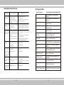
1
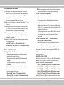
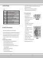
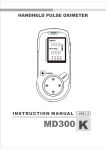
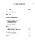
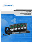
Wireless Smart Alarm System
User’s Manual
(2006 .6 Publish)
Please Read This Mannual Carefully Before You Operate
Table Of Contents
13 Testing-------------------------------------------------------------(16)
14 Installer’s Program Guide-----------------------------------(16)
1 Summary--------------------------------------------------------------(3)
14.1 How To Enter Installer’s Program State---------------------(17)
2 Function Instruction ----------------------------------------------(3)
14.2 How To Recover To The Old User Code (0000) ----------(17)
3 Definition -------------------------------------------------------------(3)
14.3 How To Recover To Ex-factory Default State--------------(17)
4 Name Of Main Parts-----------------------------------------------(4)
14.4 How To Register Remote Controller-------------------------(18)
5 How To Open/Close Outer Cover-----------------------------(5)
6 Inner Structure Diagram-----------------------------------------(5)
14.5 How To Delete Remote Controller ---------------------------(18)
14.6 How To Register Detector--------------------------------------(18)
14.7 How To Delete Detector ----------------------------------------(19)
7 System Components ---------------------------------------------(6)
15 How To Connect With Alarm Center --------------------(19)
8 Indicate Sound Instruction -------------------------------------(7)
15.1 Set CONTACT ID Account-------------------------------------(19)
9 User’ Program Guide ---------------------------------------------(7)
15.2 Set Alarm Center Telephone Number-----------------------(20)
9.1 Program Precautions-------------------------------------------------(7)
15.3 Open/Close Low Power Report Function------------------(20)
9.2 How To Enter User’s Program State------------------------------(8)
15.4 Stop Connecting With Network-------------------------------(20)
9.3 How To Modify User Code-------------------------------------------(8)
16 Ex-factory Default State-------------------------------------(21)
9.4 How To Set Alarm Telephone Numbers --------------------------(8)
17 Main Technical Specifications ----------------------------(21)
9.5 How To Delete Alarm Telephone Numbers----------------------(10)
18 Simple Failure Recovery------------------------------------(23)
9.6 How To Set Alarm Duration -----------------------------------------(10)
19 Program Table--------------------------------------------------(24)
9.7 How To Set Leaving Time -------------------------------------------(11)
20 Wireless Detector ---------------------------------------------(25)
9.8 How To Set Wireless Siren------------------------------------------(11)
21 Wireless Door Sensor ---------------------------------------(30)
<1> Open Wireless Siren ----------------------------------------------(12)
<2> Enter Wireless Siren Code --------------------------------------(12)
<3> Close Wireless Siren ----------------------------------------------(12)
9.9 How To Open/Close Phone Line Cutting Indicate Function-(12)
9.10 How To Exit Program State ---------------------------------------(13)
10 Remote Controller’s Operation Guide--------------------(13)
11 Simulate To Alarm And Operate By Telephone When
Answering Alarm Telephone---------------------------------(13)
12 Install Precautions And Processes------------------------(14)
●
1
●
●
2
●
Wireless Smart Alarm System (3-in-1)
Emergency Alarm: Alarm can be activated immediately even in disarm
state.
Monitor: When alarm occurs, you can hear the sound on alarm scene
by telephone remotely.
1 Summary
Wireless Smart Alarm System (3-in-1) adopts
micro-processing chip as control core, and it intelligently recognizes the
temperature triggered by human body. So when intruded illegally, the
main unit will linkage with wireless alarm siren to make alarm sound.
At the same time, the main unit will dial alarm manage center number
and other pre-set telephone numbers automatically. Moreover, when
answering telephone, user can arm and monitor remotely. So it is very
suitable for families, shops and other anti-intrude places.
4 Name Of Main Parts
● It’s beautiful and smart, and has multifunction.
● Built-in high decibel buzzer can alarm on-spot to frighten thief.
● It can automatically dial five groups of alarm telephone numbers
when alarming, and can be set to be compatible pulse and DTMF
(double tone multi frequency). It also can pause when dialing, and
can be used in exchanger system.
● System supports wireless alarm siren
● It is compatibles with ADEMCO CONTACT ID format.
● Low power report function
● When answering telephone, you can arm, disarm, monitor and start
on-spot alarm remotely.
● It can be set 5 remote controllers and 6 wireless detectors, and it
learns code automatically.
● The main unit built-in PIR detect module
3 Definition
Arm: The system enters defense state and can receive alarm signals.
Disarm: The system exit defense state and can’t receive alarm signals
(Except for emergency alarm)
●
3
●
PH ON E
2 Function Instruction
6
1
Picture 1 Top View
Picture 2 Front View
Picture 3 Lateral View
① Cover-Opening Hole
② Antenna
③ Detecting Window
④ Buzzer
⑤ Monitor Hole
⑥ Telephone Interface (When programming, it connects with
telephone machine; In working state, it connects with city line)
⑦ DC Input Interface
●
4
●
5 How To Open/Close Out Cover
5.1 Open
5.2 Close
PHONE
③
PH ON
PH O N
④
E
E
PHONE
PH ON E
Picture 4
Picture 5
Pi ctu re 8
Picture 7
P ic tu re 6
P ic tu r e 9
1 Mount two fasteners as picture 7
2 Make inner lines in order, (Note: Don’t Press at the
battery container.) and close the telephone interface,
then press the cover down, and check if it is closed.
1 Insert “—” type screwdriver vertically into the
cover opening hole as picture 4
2 Unclench the “—” screwdriver to the direction
as picture 5, and the cover will be opened
automatically.
6 Inner Structure Diagram
⑤
⑥
⑦
⑧
⑨
⑩
If you do not inserted the jumper, the detecting distance can
reach to 10 meters (H).
“L” level is recommended.
Program Switch: Adjusting it to “SET” position, the main unit will
enter program state ;Adjusting it to “EXIT” position, the main unit
will exit program state to normal state
Telephone Interface: When programming, it connects with
telephone machine;In working state, it connects with city line.
Arm Indicator: It is on in arm state, and it is off in disarm state.
Alarm Indicator: It is on when alarming.
DC Input Interface : Input with DC 12V±5% 300mA.
Backup Battery Connection Socket
Microphone Connection Socket
Buzzer Connection Socket
7 System Components
+
SPK
-
1
2-> L
2-> H
GAIN
1
1 2
ARM
+
1
Wireless Siren
Wireless Door Sensor
9
-
+
+
8
ALARM
-
MIC BATT
+
6
Set
Exit
CONTACT ID Network Center
Wireless PIR Detector
Picture 10
① Backup Battery: 5 PCS rechargeable batteries, battery
size: AAA 600 mAh 1.2 V.
② Detect Distance Selection: There are two levels of detect
distance to select.
If you insert with jumper, the detecting distance can reach to
8 meters (L)
●
5
●
Telephone
Office
Wireless Remote Controller
Main Unit
P icture 11
●
6
●
Mobile Phone
Telephone
8 Indicate Sound Instruction
8.1 Powered On Sound Indicator: When powered on, the main unit
makes four Bi (Bi, Bi, Bi, Bi) and the sound change gradually, which
means the system has inspected itself and it is normal. Then it
makes a “Bi” sound every second. After 100 seconds, the main unit
enter arm state automatically and begin to defense.
8.2 Low Power Sound Indicator: The main unit makes a long “Bi--” every
15 seconds.
8.3 Leaving Time Sound Indicator: After armed, the main unit makes
a “Bi” sound every second, which means the system is in leaving
time, so you should leave the defense area immediately.
8.4 Entering Program Sound Indicator: Adjust the program switch to
“Set” position, the main unit will make four Bi (Bi, Bi, Bi, Bi)
continuously immediately.
8.5 Sound Indicator In Program State: In program state, you can see if
your operations are valid.
A short “Bi” sound ----------The operation is valid
Two short Bi (Bi--, Bi--) sound----------The operation is invalid
9 User’s Program Guide
9.1 Program Precautions!!!
● When programming, power should be provided by external
power by adapter instead of battery).
● The telephone should be standard DTMF (double tone multi
frequency).
● The telephone should be equipped with battery before
programming.
● Please pick up telephone receiver instead of free hand when
programming.
● Every step, it makes indicate sound
One short “Bi” sound ---- The operation is valid.
Two long Bi (Bi--, Bi--) sound ---- The operation is invalid
●
7
●
● After entering program state, the system will enter disarm state
automatically, so you must arm again after programming.
9.2 How To Enter User’s Program State
① Open the outer-cover
② Connect with external power
③ Connect alarm host with telephone machine by double-end
telephone line
④ Adjust the Program Switch to “Set” position ( you will hear four
Bi (Bi, Bi, Bi, Bi) continuously, and the two indicator light will be
flashing at the same time.)
⑤ Pick up telephone receiver ,and enter 0000# (0000 is user’s code).
You will hear a short Bi sound, which means the setting is
successful)
9.3 How To Modify User Code
(Default State:0000)
Enter [9#]+[new code#]+[new code#]
Note: After modifying code, the original code (0000) will invalid
automatically, you must enter the new code in future.
You are suggested to modify the original code (0000) after
purchasing.e.g. If you want to change the original code “0000” to be
“1234”,you can operate as follows:
In user’s program state
Enter [9#]+ [1234#]+ [1234#]
(Note: Every time you enter “#”, it will make a short “Bi” sound, which
means the operation is correct. Otherwise, the operation is wrong.)
9.4 How To Set Alarm Telephone Numbers
Enter [11# ]+[Phone No.#] to set the 1st telephone number.
Enter [12# ]+[Phone No.#]to set the 2nd telephone number
Enter [13#]+ [Phone No.#] to set the 3rd telephone number
Enter [14#]+[Phone No.#] to set the 4th telephone number
Enter [15#]+[ Phone No.#] to set the 5th telephone number
Enter [16#]+[ Phone No.#]to set the alarm center umber. (See Chapter
●
8
●
of How to Connect With Alarm Center)
The above phone No. is available for telephone number and mobile
number
Note:
① Each group of number (including *) should not beyond 20 digits
② If you have entered wrong number, please delete it and enter the
correct once again.
③ When alarm occurs, the system will dial from the 1st group to
the 5th group of alarm telephone numbers in order, and dial 5
times periodically. If you do some effective manages when
answering telephone, the main unit will not dial this telephone
next time.
④ During entering telephone numbers, use a “*” as pause for 2
seconds, the number of “*” is subjected to the needs. It is mainly
used in small exchanger, group telephones and so on.
⑤ Add a “*” after entering telephone number, which denotes that it
adopts pulse dial mode. Otherwise, it adopts DTMF (double tone
multi frequency) mode.
Example1: Set the first alarm telephone number to be“1234567” by
DTMF
In user’s programming state,
Enter [11#]+[12345678#] (Every time you enter “#”, you will hear a
short “Bi” sound, which means the operation is valid. Otherwise, the
operation is invalid)
Example2: Set the second alarm telephone number to be “3456789”
by Pulse.
In user’s programming state
Enter [12#]+[23456789*#] (Every time you enter “#”, you will hear a
short “Bi” sound, which means the operation is valid. Otherwise, the
operation is invalid)
Example 3: Set the third alarm telephone number, which is your
company’s extension. The switchboard number is “2345678” and the
●
9
●
extension number is “808” by DTMF.
In user’ programming state,
Enter [13#]+[2345678**808#] (Every time you enter “#”, you will hear
a short “Bi” sound, which means the operation is valid. Otherwise, the
operation is invalid)
In this way, when system dialing this telephone number, it will dial
“2345678”first, and pause 4 seconds, then dial “808” automatically.
A “*” means pause for 2 seconds, and the number of “*” is subjected to
the needs.
9.5 How To Delete Alarm Telephone Numbers
Enter [11##] to delete the 1st alarm telephone number
Enter [12##] to delete the 2nd alarm telephone number
Enter [13##] to delete the 3rd alarm telephone number
Enter [14##] to delete the 4th alarm telephone number
Enter [15##] to delete the 5th alarm telephone number
Enter [16##] to delete the alarm Center telephone number
Enter [19##]to delete all telephone numbers (Including Alarm
Center Telephone Number)
Example1: Delete the second group of alarm telephone number.
In user’s programming state,
Enter [12#] +[#] (Every time you enter “#”, you will hear a short “Bi”
sound, which means the operation is valid. Otherwise, the operation is
invalid)
Example2: Delete all alarm telephone numbers (Including Alarm
Center Telephone Number)
In user’s programming state,
Enter [19#] +[#] (Every time you enter “#”, you will hear a short “Bi”
sound, which means the operation is valid. Otherwise, the operation is
invalid)
9.6 How To Set Alarm Duration
In user’s programming state (Default: 2 Minutes)
Enter [23#]+[Duration#]
●
10
●
The duration ranges: 00--05 minutes, so it must be 2 digits when
entering.
If you enter “00”, the system will be in mute alarm.
Example 1:Set it to be mute alarm
In user’s programming state,
Enter [23#] +[00#], (Every time you enter “#”, you will hear a short
“Bi” sound, which means the operation is valid. Otherwise, the
operation is invalid)
Example 2: If you want to set 3 minutes for alarm duration
In user’s programming state,
Enter [23#]+[03#] (Every time you enter “#”, you will hear a short “Bi”
sound, which means the operation is valid. Otherwise, the operation is
invalid)
9.7 How To Set Leaving Time (Default:00 Second)
Leaving time means the main unit will delay to arm for some time when
you press “Arm” key on remote controller.
Enter: [24# ]+[leaving time#]
Leaving time ranges: 00--99 seconds, so it must be 2 digits when
entering.
During leaving time, the system will make a “Bi” sound every second,
and you must leave defense area during the time.
Example1: Set the system automatically enters arm state 30 seconds
later when pressing “Arm” key on remote controller.
In user’s programming state,
Enter [24#] +[30#] (Every time you enter “#”, you will hear a short “Bi”
sound, which means the operation is valid. Otherwise, the operation is
invalid)
9.8 How To Set Wireless Siren
Duration of wireless siren depends on alarm host. If host duration is 00
(mute), the wireless siren will be mute too. If the host duration is 03
minutes, the wireless siren duration will be 03 minutes too, so you can
view it as an external siren of alarm host.
●
11
●
<1> Open Wireless Siren (Default: Close)
If you want to use wireless siren, you must open it firstly.
In user’s programming state:
Enter [25#] to open the wireless siren, the system will make a
short “Bi” sound, which means the setting is successful.
<2> Enter Wireless Siren Code
Enter [27#] + [code of wireless siren#] (code of wireless siren
is 8 digits labeled at the back of wireless siren. (Every time you enter
“#”, you will hear a short “Bi” sound, which means the operation is
valid. Otherwise, the operation is invalid)
Example 1: Collocate a wireless siren, and the code is “33121021”.
In user’s programming state,
Enter [27#] + [33121021#], (Every time you enter “#”, you will hear a
short “Bi” sound, which means the operation is valid. Otherwise, the
operation is invalid)
<3> Close Wireless Siren
If you don’t want to use wireless siren, you don’t need to delete it, but
close it.
In user’s programming state
Enter [26#] to close the wireless siren, the system will make a short
“Bi” sound, which means the setting is successful.
9.9 How To Open/Close Phone Line Cutting Indicate Function
(Default: Close)
Phone line cutting indicate function means the system will make
indicative sound when telephone line cutting or badly connected.
Opening:
In user’s programming state,
Enter [5#] to open phone line cutting indicator, it will make a short “Bi”
sound, which means the setting is successful
Closing:
In user’s programming state,
Enter [6#] to close phone line cutting indicator, it will make a short “Bi”
●
12
●
sound, which means the setting is successful
9.10 How To Exit Program State
After programming, adjust program switch to “Exit” position, and the
two indicators light stop flashing, which means it has exited program state.
10 Remote Controller’s Operation Guide
<1> Arm: Press on remote controller, the main unit will make a
short “Bi” sound, and enter arm state, the arm indicator on
host will be on.
<2> Disarm: Press on remote controller, the main unit will make
two short “Bi” sound continuously, and enter disarm state, the
arm and alarm indicator will be off.
<3> Emergency Alarm: Press on remote controller, the main unit
will enter alarm state immediately.
11 Simulate To Alarm And Manage Alarm By
Telephone When Answering Alarm Telephone
Connect the host with line socket with double-end cable. Press
“Emergency” key on remote controller, the main unit will make alarm
sound immediately. Then system will dial the pre-set phone. Pick up
telephone receiver (If the telephone you operate is mobile phone,
please press “Receive” key on mobile phone), you will hear alarm sound
for about 5-10 seconds, after that, you will hear a short “Bi” sound, then
you can enter the following commands:
Enter [1#]-------- The system enters arm state immediately
(If the system is in alarm state, it should be disarmed firstly,
then it can be armed).
Enter [2#]--------The system will stop alarming, enter disarm
state immediately and don’t dial other telephone numbers.
Enter [3#]---------The system activates alarm at scene
immediately.
Enter [4#]-------You can monitor at scene for 10 seconds
●
13
●
Enter [0#]-------The main unit will hang up telephone and
don’t dial this telephone number unless alarm occurring again.
Note: “2#” “3#” “4#” are not limited in order and times, and the main
unit will wait for 20 seconds to receive commands. If there are no any
operations within 20 seconds, the main unit will hang up this telephone
automatically, and then go on dialing other alarm telephones.
After testing, close the out cover of main unit as 5.2 chapter,
then you can begin to install.
12 Install Precautions And Processes
12.1 Install Precautions
<1> The infrared detector has the highest sensitivity when
human body moves parallel with mirror surface as
picture 12, and the sensitivity is the lowest when human
body moves vertically against mirror surface as picture13,
so you must install it as picture 12.
Note: R means the detect distance radius
transverse movement (top view)
vertical movement (top view)
R
R
×
√
Picture 12
Picture 13
<2> It only can be used indoors, so when installing, it should
stand off sunshine and other break-out lights (such as car
light)
●
14
●
<3> Stand off warm or cold sources. e.g. warm or cold air
outlets, electric radiators, air-cooling machines and etc ;
<4> Stand off doors and windows.
<5> There should be no barriers in defense area.
Window
Barrier
air conditioner
13 Testing
13.1 After powered on, the main unit will make a short “Bi” sound every
one second, and the arm indicator will be flashing, after 100 seconds,
the arm indicator will be on, which means the main unit has entered
arm state, then begin to work.
You can simulate to pass the defense area from the direction as picture
15 to see if the main unit will alarm.
(Top View)
shield by desk or other things
× × ×
Picture 14
<6> The landscape orientation it can detect is about 90°, so
when installing, the area want to be defended should be
within the detect areas.
12.2 Install Processes
10-30°
①
2m
③
②
Detect Distance
1.The angle and height against the horizontal
surface should be noted during installation,
which will greatly affect the defense area.
The installation height should be about 2 m,
and the angle against the wall should be
about 10-30°as above picture.
2.Press universal coupling
into universal base lightly
④
⑤
3.Firmly fix the universal coupling
with nails on the place where
you want to fix it.
Telephone
Adapter
Outside Line
⑥
4.Hang the main unit on the universal
coupling and buckle it firmly.
5.Adjust the angle of main unit
according to install precautions.
●
15
●
6.Insert the adapter to electric socket,
then connect the plug with main unit,
and then connect telephone outside
line with telephone interface on main unit.
Picture 16
Picture 15
Picture 17
● If the main unit don’t alarm, which means the install position, angle
and height may be wrong, so you must disarm it firstly, and re-adjust
the main unit , and arm it to test again till it makes alarm sound.
● If the main unit alarms, please disarm it firstly, and leave the defense
area, then arm it again. After 10 seconds, you can pass the defense
area from the other direction to see if the main unit will alarm.
● After several times of testing, if the main unit alarm every times,
which means the installation is correct, and the setting is successful.
13.2 To assure the affection, please pull the antenna out as picture 16.
13.3 Check to see if the main unit is fixed firmly, if main unit is loosed,
please nail universal coupling with tapping screw lightly as picture 17
14 Installer’s Program Guide
What Installer’s programmed have an important relations with system’s
●
16
●
performance. Therefore, you must pay much attention to manager’s
program.
14.1 How To Enter Installer’s Program State
Adjust the program switch to “SET” position, pick up telephone receiver,
and enter “12*48#”, then you will hear a short “Bi” sound, which means
it has entered Installer’s program state.
14.2 How To Recover To The Old User Code (0000)
If you lose or forget your user code, you can recover to old user code to
default (0000) by operating as follows:
In Installer’s programming state, enter “1#”, you will hear a short “Bi”
sound, which means the setting is successful, and the user’s code
recovers to ex-factory default state (0000).
14.3 Recover To Ex-factory Default State (Pay Much Attention
When Operating)
If the system can’t work normally without any sakes, moreover, it can’t
be settled by other ways. You can operate as follows to recover to
ex-factory default state.
In installer’s programming state, enter “2#”, after several seconds, you
will hear a short “Bi” sound, which means the operation is correct, and
all setup will recover to ex-factory default state. All remote controllers,
detectors, phone numbers set previously will be cleared, and you must
set it again.
14.4 How To Register Remote Controller (5 at most)
In installer’s program state
Enter [11#]to register the 1st remote controller
Enter [12#] to register the 2nd remote controller
Enter [13# ]to register the 3rd remote controller
Enter [14#] to register the 4th remote controller
Enter [15# ]to register the 5th remote controller
Example: Register the third remote controller
In Installer’s program state,
Enter [13#], after hearing a short “Bi” sound, press “Arm” key on remote
controller, you will hear a short “Bi” sound again, which means the
●
17
●
setting is successful.
After setting, you must arm the main unit to check .
14.5 How To Delete Remote Controller
If some remote controller you don’t want to use, you can delete it by
entering commands as follows:
Enter [11##] to delete the 1st remote controller
Enter [12##] to delete the 2nd remote controller
Enter [13##] to delete the 3rd remote controller
Enter [14##] to delete the 4th remote controller
Enter [15##] to delete the 5th remote controller
Enter [19##] to delete all remote controllers
Example 1: Delete the second remote controller
In Installer’s programming state
Enter [12#], after hearing a short “Bi” sound, press “#”, you will hear a
short “Bi” sound again, which means the setting is successful.
Example 2: Delete all remote controllers
In manager’s programming state, enter “19#”, after hearing a short “Bi”
sound, press “#”, you’ll hear a short “Bi” sound again, which means all
remote controllers are deleted.
14.6 How To Register Detector (6 at most)
Enter [21#] to register the 1st wireless detector
Enter [22#] to register the 2nd wireless detector
Enter [23#] to register the 3rd wireless detector
Enter [24#] to register the 4th wireless detector
Enter [25#]to register the 5th wireless detector
Enter [26#] to register the 6th wireless detector
Example 1: register the first wireless detector (PIR detector)
In installer’s program state, enter [22#], after hearing a short “Bi”
sound, put ON/OFF switch to ON position to power on PIR detector.
When the emit indicator flash for a moment, you’ll hear a short “Bi”
sound again, which
means the setting is successful.
Note: Before collocating, PIR detectors should be powered on for 2
minutes firstly.
●
18
●
Example 2: Register the second wireless detector (Wireless door sensor)
In installer’s program state, enter “23#”, after hearing a short “Bi”
sound, separate the door sensor. When the emit indicator flash for a
moment, you’ll hear a short “Bi” sound again, which means the setting
is successful.
After setting, you must arm the main unit to check
14.7 How To Delete Detectors
If some detector you don’t want to use, you can delete it by entering
commands as follows:
Enter [21##] to delete the 1st wireless detector
Enter [22##] to delete the 2nd wireless detector
Enter [23##] to delete the 3rd wireless detector
Enter [24##] to delete the 4th wireless detector
Enter [25##] to delete the 5th wireless detector
Enter [26##] to delete the 6th wireless detector
Enter [29##] to delete all wireless detectors
Example1: Delete the first detector
In manager’s programming state
Enter [21#], after hearing a short “Bi” sound, press [#], you will hear a
short “Bi” sound again, which means the setting is successful.
Example 2: Delete all detectors
In manager’s programming state, enter [29#], after hearing a short “Bi”
sound, press [#], you’ll hear a short “Bi” sound again, which means all
remote controllers are deleted
After program, adjust the Program Switch to “Exit” position
15 How To Connect With Alarm Center
15.1 Set CONTACT ID Account
If you want to connect with alarm center, you must set
CONTACT ID Account firstly in order to make Alarm Center to
distinguish which alarm system (Be in on-line state) is alarming.
In installer’s Program, Enter [5#] + [BBBB#] (BBBB is ID account,
which ranges from 0001-9999, and it must be 4 digits)
●
19
●
Example 1: Set the ID Account to be “1234”.
Adjust the program switch to “Set” position, after hearing a short “Bi”
sound, pick up telephone receiver, enter 12*48#, you will hear a Bi, and
enter 5# (you will hear a Bi), then enter “1234#”, you will hear a short
“Bi” sound again, which means the setting is successful.
15.2 Set Alarm Center Telephone Number
If you want to open alarm center function, you must set Alarm Center
telephone number firstly.
In User’s Program state (user’s code 0000 default), enter [16#] +
[Phone No.#]
Example 2: Set Alarm Center telephone number to be “1234567”
Adjust the program switch to “Set” position, after hearing a short “Bi”
sound, pick up telephone receiver, then enter User’s Code and plus #
(0000#), and enter “16#”, you will hear a short “Bi” sound again, then
enter “1234567#”, you will hear a short “Bi” sound again, which means
the setting is successful.
15.3 Open/Close Low Power Report Function (Default: Close)
In User’s Program state
Enter [7#] ----- Open report function
Enter [8#]----- Close report function
When system backup battery voltage is low, whether to inform alarm
center or not when system backup battery voltage is low can be set
This function only valid to Alarm Center
Adjust the program switch to “Set” position, after hearing a short “Bi”
sound, pick up telephone receiver, then enter user code (0000), then
plus “#”, you will hear a short “Bi” sound again, which means the
setting is successful.
Enter [7#], if you hear a short “Beep” sound , which means
report function has been opened.
Enter [8#], if you hear a short “Beep” sound , which means
report function has been closed.
15.4 Stop Connecting With Alarm Center
In User’s Program state, Enter [16##]to delete the alarm center phone
●
20
●
Number
If you don’t want to connect with Alarm Center, you can delete the
Alarm Center telephone number as following:
Adjust the program switch to “Set” position, after hearing a short “Bi”
sound, pick up telephone receiver, then enter user’s code, then enter [#],
you will hear a short “Bi” sound again, and enter [16#] after hearing a
short “Bi” sound, enter [#] again, it will make a short “Bi” sound again,
which means the setting is successful.
16 Ex-factory Default State
16.1 All Indicator Lights Default State: Open
16.2 Telephone Line-cutting Detect Function: Close
16.3 System Low Power Report Function: Close
16.4 Alarm Telephone Numbers: Empty
16.5 Infrared Mode: Standard Mode
16.6 Alarm Duration: 2 Minutes
16.7 Leaving Time: 00 Second
16.8 Wireless Siren: Close
16.9 Wireless Siren Code: 00000000
16.10 User’s Code:0000
16.11 Remote Controller: Empty
16.12 Detector: Empty
17.9 Alarm Loudness: ≥100dB within 1m
17.10 Frequency:433.92MHz
17.11 Dial Index:
① DTMF(Double Tone Multi Frequency)Mode:
High Frequency Extent:-7±2dBm
Low Frequency Extent:-9±2dBm Distortion Factor:≥ 20dB
② Pulse Mode:
Pulse Speed:10±1PPS
Pulse Ratio:2:3
17.12 Wireless Remote Controller:
Working Voltage:DC 12V (Alkaline battery, Size: 27A 12V)
Remote Control Distance: ≥100m(In Open Area)
17.13 Alarm Center Format: ADEMCO CONTACT ID Format
17 Main Technical Specifications
17.1 Working Environment:-20℃ --50℃,
17.2 Built-in Back Up Battery: 5PCS No.7 600 mAh Ni-MH
rechargeable battery
17.3 Input DC Voltage:DC12V ±10%, 300mA
17.4 Standby Time: ≥ 20 hours
17.5 Standby Current: ≤20mA
17.6 Infrared Blocking Time While Power On:100 seconds
17.7 Detect Distance: 6-12m
17.8 Level Detect Angle: horizontal:90°,vertical:60°
●
21
●
●
22
●
18 Simple Failure Recovery
19 Program Table:
User’s Program
Fault Symptoms
Failure Reasons
Failure Recovery
There are not indicate
sound when powered
on
1 The power socket may be bad
or badly connected.
2 There is no power supply.
3 The inner buzzer is badly
connected.
1 Check and connect the socket
2 Power the socket on
3 Open the out cover, check if the power and
buzzer are well connected .
You
can’t
program state
1
It can’t meet program’s
requirements.
Forget user’s code
1. Please read program precaution’ chapter
carefully to see if it meets the requirements.
2. Refer to program chapter to recover user’s
code.
1 Use city line to go on network..
The outside line connect with
main unit without extension
socket
2 Program operation is wrong.
3The telephone number is wrong.
1 The city line connected with main unit shall
be
connected
from
extension
socket.
.
2 When programming, it should meet the
program requirements.
3 Refer to telephone number setting, and enter
the right telephone numbers again.
1 The installment of main unit
and detector can’t meet the
requirements.
2 Battery power is low
1 Install main unit and detector according to
install requirements.
2 Replace the battery
The
communicate 1 There are barriers in the
distance
between
defense area.
main unit and remote 2 Battery power is low.
controller,
PIR
detector, door sensor
become shorter.
1 Closer to main unit as possible to reduce
barriers.
2 Replace the battery.
enter
2
It can’t dial alarm
telephone
numbers
when alarm occurs.
False Alarm
When monitor, you
can’t hear the scene
sound clearly.
1 The signal is bad.
1 If the signal is bad, please ask relative
2 There are noisy in telephone
personnel for help.
answering place
2 Avoid the noisy sound in telephone
answering place.
When
answering
alarm telephone, the
command entered is
invalid.
The distance between main unit
and telephone is too near.
●
23
●
Telephone machine located should be far
away from main unit.
(Code: Ex-factory Default State:0000)
7#
Open telephone line-cutting indicate
function
Close telephone line-cutting indicate
function
Open battery low voltage report function
to alarm center
8#
Close battery low voltage report function
to alarm center
9#
Modify user code
11# -15#
Set alarm telephone numbers from the 1st
group to the 5th group
11##-15##
Delete alarm telephone numbers from the
1st group to the 5th group
16#
Set CONTACT ID center telephone number
5#
6#
19##
Delete CONTACT ID center telephone
number
Delete all telephone numbers at one time
(including manage center)
23#Duration time#
Alarm duration time (Duration time
arrange: 00-05 minutes)
24#Leaving time#
Leaving time (Leaving time range: 00-99
seconds)
25#
Start up wireless siren
26#
Shut down wireless siren
27#code of wireless siren#
Set wireless siren, code of wireless siren is
8-digit labeled at the back of wireless siren
16##
●
24
●
Installer’s Program
12*48#
1#
2#
5#
11#-15#
11##-15##
19##
21#-26#
21##-26##
29##
Recover user code to be ex-factory default state (0000)
Recover to ex-factory default state
Set CONTACT ID code (default state is 0000)
Collocate 1-5 remote controllers
Delete 1-5 remote controllers
Delete all remote controllers at one time
Collocate 1-6 detectors
Delete 1-6 detectors at one time
Delete all detectors at one time
20 Wireless Infrared Detector
Wireless Passive Infrared Sensor adopts advanced digital
signal processing technology with automatic temperature compensation,
Lower power alert and timing communication report function. It detects
human infrared heat energy to emit wireless digital signal to activate
main unit. It is advantage of stability, easy installation and low alarm
error ratio.
20.1 Main Functions And Features
①It adopts double infrared sensor, and has high sensitivity.
②Single-chip intelligent digital processing
③Double-channel intelligent signal processing
④Low power consumption design, static current≤50μA, anti-pet,
anti-electromagnetism
interference and low rate of false alarm
⑤Three classes of sensitivity.
⑥Automatic temperature compensation
●
25
●
⑦Adapter DC9V-12V is available. Automatically switch between inner
power and external power.
⑧When power lower, it alerts and reports to main unit
⑨Timing communication report and ON/OFF report.
20.2 Technical Parameter
① Detective Distance ≤8m
② Detective Angle: 90°
③ Working Voltage: DC6V (4pcs No.7
dry batteries), and external power
(adapter): DC9V 12V.
④ Working Current:
Power supplied by battery, Standard
current ≤ 50μA, Alarm current
≤15mA
Power supplied by the adapter,
Standard current ≤ 5mA, Alarm
current ≤20mA
⑤ Blocked time when it is power
on: 100 seconds
⑥ Emission Time: 3 seconds
⑦ Emission Frequency: 433.92MHz
⑧ Emission Power≤70mW
⑨ Physical Size: 110mm X 60mm X 45mm
⑩ Working Temperature:-25℃~65℃
●
26
●
20.3 Component Description
20.3.1Working Mode:
There are three Working Modes --- Testing Mode, Standard Mode, Power
Saving Mode.
A: Testing Mode:
After it sends a signal,
the sensor won’t send
a new signal until 5
seconds. It is recommended
for debugging. This mode
runs more power.
B: Standard Mode:
After it sends a signal, the
sensor won’t send a new
signal until 60 seconds. It
is recommended for daily
work.
C: Power Saving Mode:
After it sends a signal, the
sensor won’t send a new
signal until 240 seconds. It
is used in marketing place
where have more people in
and out.
Note:The mode shall be changed when powered off (Including
battery power).
20.3.2 Tamper: When DOS shell is opened or destroyed illegally,
infrared detector will send signal to main unit and activate alarm.
Tamper alarm can be activated in 24 hours a day. Even the sensor is
in power off state.
20.3.3 Power On/Off: Adjust switch to “ON” position, the
detector will start to work; Adjust switch to “OFF ” position, the
●
27
●
detector will stop working and report to main unit at the same
time.
20.3.4 External DC Input: DC9V~12V is available. External
power supplied and inner power supplied can be changed a
utomatically.
20.4 Installation Requirements and Diagram
20.4.1 Installation Requirements
The infrared detector has the highest sensitivity when a human
body moves parallel with the
mirror surface and the sensitivity is the lowest when a human
body moves vertically against the
mirror. So the angle and height against the horizontal surface
should be noted during installation,
which will greatly effect the range of the defense area .The height
should be 2 meters or so and it
should be installed parallel with wall.
Stand off straight light and other straight light sources (e.g. car
light)
Stand off warm or cold sources, e.g., warm air or cold air outlet,
air conditioning outlet, electric
radiators, air cooling machines and etc. stand off windows.
There are no barriers within defended area of a detector.
If infrared detector works in a temperature that is near to human
temperature, the detection is
inefficient. So in this instance, Infrared detector is suggested to
be installed in lower temperature
in that area.
In interference instance, infrared detector is suggested to be set
in low sensitivity position.
Infrared detector is asked to be fixed on the wall without swaying.
20.4.2 Diagram
Open top cover of detector, select the sensitivity class and
●
28
●
working mode according to security
requirements. Install 4pcs No.7 batteries according to battery
case remark., And adjust ON/OFF
switch to “ON” position, and fix it on the wall.
2. Transmitting Code Jumper Working Mode Select
Normal Mode Sensitivity 8m 6m
1.Open cover as picture shows
Top View
After powering on for 100 seconds, human body motions in 0.75m/S
by 8-10m in distance. Its alarm indicator is on and it activates main unit.
That means installation is right and success.
Note
To make sure its sensitivity, infrared sensor is not allowed to be touched
by hand. And have to keep clear. If the surface is dirty, power it off, and
clear it with a cotton ball dipped in 75% alcohol.
Test infrared detector periodically
This infrared detector can prevent theft conduct, but not ensure to be
no risks at all. For security, users are asked to use this products correctly
and improve alert.
21 Wireless Door Sensor
3.Press universal ball into
universal bearer. To void
damaged, please energize
on average.
4.Fix universal bracket
with nail on 2m over
horizontal.
6.top view, adjusting detector area
right and left,
5.Fix infrared detector
in universal bracket.
21.1 Instruction
Wireless door sensor matches with a magnet. It sends
alarm signal to main unit when both parts separated. The door sensor
is designed in micro power consumption with low power alert. The
wireless transmitter adopts SAWF. It is more stable. The transmitting
distance in open area can reach to 250 m or more.
7.side view, adjusting up and down
installation finished detector
20.4.3 Indicator
Alarm Indicator: When alarm happens, alarm indicator will be flashing
Lower Power Indicator: When lower power, the corresponding
indicator will be on.
20.4.4 Simulating Demo
●
29
●
●
30
●
21.2 Installation
Remove the paper on double-faced glue on both door sensor and magnet.
Glue sensor and magnet in the proper place you want. Be sure the
antenna of door sensor to be in uprightness (up or down).
21.3 Note
1.The magnet part is asked to be installed in mobile door or window.
For example, install magnet part on mobile place. And install sensor
part on fixed place.
2.The distance of both magnet part and sensor part should not
beyond 20mm.
3. Please pull out the antenna to be sure the wireless Tran receiver
affection.
4. Please replace the battery once you find the Alarm/Low Power
Indicator is in red.
21.4 Component Diagram
① Transmitting Code Jumper: To change wireless code with
jumper place
② Magnet: To match with sensor to perform alarm
③ Low Power Indicator: Red indictor for low power
④ Alarm Indicator: Yellow indictor for alarm
●
31
●