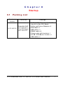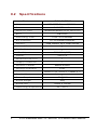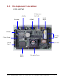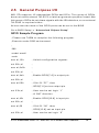
1
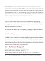
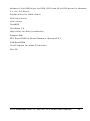
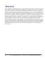
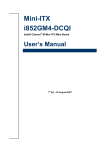
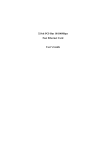
ICOP-6037VE Embedded 5x86 3.5"-size All-in-One CPU Board User’s Manual (Version 1.0) Copyright Notice This document is copyrighted, 2001 by ICOP Technology Inc. All rights are reserved. The information in the manual is subject to change without notice in order to improving products. No part of this manual may be reproduced, copied, translated or transmitted in any form or by any means without the prior written permission of the manufacturer. ICOP Technology Inc. assumes no responsibility for any inaccuracies that may be contained in this document. ICOP Technology Inc. makes no commitment to update or to keep current the information contained in this manual. Copyright 2001 by ICOP Technology Inc. All rights reserved. Ver.1.0 2001, Printed in Taiwan Trade marks Acknowledgments All brand names and trademarks are the properties and registered brands of their respective owners ii Table of Contents Table of Contents iii C h a p t e r 0 Startup 0.1 Packing List . . . . . . . . . . . . . . . . . . . . . . . . . . . . . . . . . . . . . . . . . . . . . . . . . . . . . . . 1 0.2 0.3 Specifications . . . . . . . . . . . . . . . . . . . . . . . . . . . . . . . . . . . . . . . . . . . . . . . . . . . . 2 Component Location . . . . . . . . . . . . . . . . . . . . . . . . . . . . . . . . . . . . . . . . . . . 3 C h a p t e r 1 Introduction 1.1 Features. . . . . . . . . . . . . . . . . . . . . . . . . . . . . . . . . . . . . . . . . . . . . . . . . . . . . . . . . . . . 4 1.2 1.3 1.4 Specifications . . . . . . . . . . . . . . . . . . . . . . . . . . . . . . . . . . . . . . . . . . . . . . . . . . . . 5 VGA Interface . . . . . . . . . . . . . . . . . . . . . . . . . . . . . . . . . . . . . . . . . . . . . . . . . . . . . 7 DiskOnChip 2000 Flash Disk . . . . . . . . . . . . . . . . . . . . . . . . . . . . . . . . . 8 1.5 Network Interface . . . . . . . . . . . . . . . . . . . . . . . . . . . . . . . . . . . . . . . . . . . . . . . 9 C h a p t e r 2 Installation 2.1 2.2 2.3 Jumper Settings . . . . . . . . . . . . . . . . . . . . . . . . . . . . . . . . . . . . . . . . . . . . . . . 10 Connectors. . . . . . . . . . . . . . . . . . . . . . . . . . . . . . . . . . . . . . . . . . . . . . . . . . . . . . 12 DiskOnChip/Flash ROM Disk . . . . . . . . . . . . . . . . . . . . . . . . . . . . . . 13 2.3.1 Setup a DiskOnChip ® 2000 Flash Disk . . . . . . . . . . . . . . 13 2.3.2 Setting up a Flash Disk . . . . . . . . . . . . . . . . . . . . . . . . . . . . . . . . . . . 14 2 . 4 Watchdog Timer . . . . . . . . . . . . . . . . . . . . . . . . . . . . . . . . . . . . . . . . . . . . . . . 15 2.5 General Purpose I/O. . . . . . . . . . . . . . . . . . . . . . . . . . . . . . . . . . . . . . . . . . 19 C h a p t e r 3 SVGA Setup 3 . 1 Introduction. . . . . . . . . . . . . . . . . . . . . . . . . . . . . . . . . . . . . . . . . . . . . . . . . . . . . 21 3.1.1 Chipset. . . . . . . . . . . . . . . . . . . . . . . . . . . . . . . . . . . . . . . . . . . . . . . . . . . . . . . . . 21 3.1.2 Display memory. . . . . . . . . . . . . . . . . . . . . . . . . . . . . . . . . . . . . . . . . . . . . 21 3 . 2 Installation of SVGA driver. . . . . . . . . . . . . . . . . . . . . . . . . . . . . . . . . 21 3.2.1 Installation for Windows 3.1 . . . . . . . . . . . . . . . . . . . . . . . . . . . . 23 3.2.2 Installation for Windows 95/98 . . . . . . . . . . . . . . . . . . . . . . . . . 25 C h a p t e r 4 Network Interface 4.1 4.2 Introduction. . . . . . . . . . . . . . . . . . . . . . . . . . . . . . . . . . . . . . . . . . . . . . . . . . . . . 27 Software Support. . . . . . . . . . . . . . . . . . . . . . . . . . . . . . . . . . . . . . . . . . . . . . 28 iii Warranty iv Chapter 0 Startup 0.1 Packing List Product Name I C O P -6037VE Function Package l I C O P -6037VE Embedded 5x86 3.5" size All-in-One CPU Board Embedded 5x86 l Utility and Drivers Diskette x 2 3.5" -size All-in- l FDD cable x 1 One CPU Board l HDD cable x 1 with VGA/LCD l RS232 cable x 2 l Printer cable with bracket x 1 l AT KB / PS2 Mouse Y-cable x 1 l VGA cable x 1 ICOP Embedded 5x86 3.5"-size AIO CPU Board User's Manual 1 0.2 Specifications Features Chipset Processor Multi I/O Chip BIOS Watchdog Timer Bus Interface Memory SGS STPC Client, 66/75 MHz 5x86 CPU on-die W i n b o n d W 8 3 9 7 7 F-A, ALi 5113 AMI BIOS From 1 to 64 seconds PC/104 standard compliant 16MB onboard, up to 32MB onboard Memory Sockets 1 DiskOnChip Socket 1 VGA Chipset Displa y C&T 69000 (2MB) VGA/LCD Enhanced IDE Port 1 Floppy Connector 1 Network Chipset Network Interface Serial Port Parallel Port Power Requirement Board Weight Board Size O p e r a t ing Temperature 2 I C O P -6037VE Realtek 8139AS RJ-45 RS232 X 2 (or RS232 X 1,RS485 X 1) 1 +5V @1.6A 300g 102mm X 144 mm -20 ~ +60°C ICOP Embedded 5x86 3.5"-size AIO CPU Board User's Manual 0.3 Component Location ICOP-6037VE Ethernet RJ -45 SVGA Buzzer COM1 PS/2 Keyb. COM2 PC/104 Conn. Flat Panel EIDE Port D C-I N FDD Port Parallel Port ICOP Embedded 5x86 3.5"-size AIO CPU Board User's Manual 3 Chapter 1 Introduction 1.1 Features l 3.5’’-s i z e ( 1 4 4 x 1 0 2 m m ) E m b e d d e d C P U M o d u l e l PC/104 connector l SGS STPC Clie n t 5 x 8 6 p r o c e s s o r w i t h F P U u n i t l CRT and Flat Panel Display interface l 16MB EDO RAM onboard and up to 32MB by expansion l Enhanced IDE devices and FDD interface l One Bi-directional Parallel Port l RS-232/485 interface l Watchdog timer l Socket for Flash or DiskOn C h i p l Onboard Keyboard, Mouse connector l Onboard Ethernet, compatible with NE2000 l Single voltage +5 V power connector l Operating temperature from –2 0 l Flexible OEM/ODM design 4 +60℃ ICOP Embedded 5x86 3.5"-size AIO CPU Board User's Manual 1.2 Specifications Chipset: SGS ST PC Client, 66/75MHz, 64-bit internal architecture x86 processor with FPU unit Enhanced IDE, Scatter/gather and Multi-word DMA Data Bus: 16-bit Bus Speeds: ISA - 8.3 MHz, PC/104 - 8.3 MHz DMA Channels: 7 Interrupt Levels: 15 Watchdog Timer: from 0.5 to 32 seconds Real-Time clock BIOS: AMI BIOS RAM : 16 MB up to 32 MB of EDO DRAM I / O: Winbond W83977F-A, ALi 5113 two floppy drives two hard drives or Enhanced IDE devices one RS -232 port, one RS -232/485 port Bi-directional Parallel Port Bus Interface : PC/104 Connector: External 9-pin D-Type male RS232 connector External 15-pin D-Type female VGA connector External 6-pin Mini DIN for AT-keyboard, PS2 Mouse 10-pin box header for RS232 port X 1 25-pin box header for parallel port 50-pin box header for flat panel VGA 2-pin header for RS485 port 34-pin box header for floppy disk drive ICOP Embedded 5x86 3.5"-size AIO CPU Board User's Manual 5 40-pin box header for enhanced IDE One socket for flash ROM or DiskOnChip RJ-45 connector for 10/100BASE-T Disp l a y: • Chipset: C&T CHIPS 69000 • Memory: 2MB integrated memory • Display: resolution up to 1024x768 @ high colors • Compatibility: VGA, TFT, DSTN, SSTN, EL, Plasma hardware • OS Support: DOS, Windows, Windows 95/98, Windows NT, Windows CE, QNX, OS/2 LAN: Realtek 8139BL single chip NE2000 compatible with built in 16 KB RAM buffer Throughput : 10/100 Mbps Power Requirements: single voltage +5 V @ 1.6 A Dimensions: 102 (L) x 144 (W) mm. Weight: 300g Operating Temperature : -20~+60 ° C 6 ICOP Embedded 5x86 3.5"-size AIO CPU Board User's Manual 1.3 VGA Interface The 69000 accelerator extends CHIPS's HiQVideo™ Series of mobile graphics/video accelerated controllers by embedding 2 MBytes of high speed SDRAM into the chip. The 69000 is the first member of the HiQVideo family to integrate high speed SDRAM frame buffer memory into the chip. Using leading edge embedded memory logic technologies, the 69000 integrates 2 MBytes of SDRAM into the chip. By embedding SDRAM and graphics controller logic on the same die, the 69000 delivers uncompromised performance and at the same time consumes much less power than the discrete solution. The integrated SDRAM supports up to 83MHz operation, which provides up to 664MBytes/second frame buffer bandwidth. The increase in the frame buffer bandwidth enables the 69000 to support high color, high-resolution graphics modes and realtime video acceleration. The 69000 is a highly integrated graphics/flat panel controller for notebooks, mini-notebook, industrial PC, and palmtop applications. By integrating 2MByte of SDRAM, graphics, flat panel, and CRT control logic on the same die, 69000 delivers superb 2D video performance, consumes minimal power and at the same time reduces the PCB real estate for the graphics subsystem. The 2MByte embedded SDRAM is arranged in a 64-bit configuration. The 69000 supports both Frame AGP and PCI bus which enables a wide range of system platforms. ICOP Embedded 5x86 3.5"-size AIO CPU Board User's Manual 7 1.4 DiskOnChip 2000 Flash Disk Flash Disk DiskOnChip ® 2000 • Package: S i n g l e C h i p F l a s h D i s k i n 3 2 -pin DIP JEDEC • Capacity: 1 -144 MByte capacity • Data Reliability: ECC/EDC error correction • Memory Window: 8 Kbyte 8 ICOP Embedded 5x86 3.5"-size AIO CPU Board User's Manual 1.5 Network Interface • Chipset: R e a l t e k 8 1 3 9 B L s i n g l e c h i p • Type: 10/100BASE-T • Connectors: o n b o a r d R J -45 connectors • Monitoring LEDs: network ready indicator, network activity indicator • Compatibility: N E 2 0 0 0 ICOP Embedded 5x86 3.5"-size AIO CPU Board User's Manual 9 Chapter 2 Installation 2.1 Jumper Settings ICOP-6037VE J14 SP1 J1 J11 J18 J7 J2 J12 J15 J3 J9 J6 J17 J4 J8 10 J10 J5 J13 J16 ICOP Embedded 5x86 3.5"-size AIO CPU Board User's Manual J14 RS-2 3 2 / 4 8 5 s e l e c t i o n f o r C o m 2 1 -2: RS-2 3 2 2 -3: R S 4 8 5 J16 DOC address select DOC address C800H (default) CA00H CC00H CE00H D800H DA00H DC00H DE00H 1-2 3-4 5-6 close close close close open open open open close close open open close close open open close open close open close open close open ICOP Embedded 5x86 3.5"-size AIO CPU Board User's Manual 11 2.2 Connectors J1 External D -type CRT VGA Display connector J2 6 4 -p i n P C / 1 0 4 b u s J3 4 0 -p i n P C /1 0 4 b u s J4 RESET Switch J5 Fan connector J6 D C -IN Power connector J7 PS2/KBD connector J8 HDD LED J9 4 0 -pin IDE connector J10 3 4 -pin FDD connector J11 9 -p i n m a l e R S / 2 3 2 c o n n e c t o r f o r C o m 1 J12 1 0 -pin RS/232 box header f o r C o m 2 J13 2 6 -pin box header for printer port J15 2 -pin RS/485 connector J17 4 4 -p i n L C D c o n n e c t o r J18 LAN RJ45 connector SP1 BUZZER 12 ICOP Embedded 5x86 3.5"-size AIO CPU Board User's Manual 2.3 DiskOnChip/Flash ROM Disk 2.3.1 Setup a DiskOnChip ® 2000 Flash Disk Installation Instructions 1. Make sure the ICOP-6026VE is powered OFF 2. Plug the DiskOnChip 2000 device(s) into its socket. Verify the direction is correct (pin 1 of the DiskOnChip 2000 is aligned with pin 1 of the socket) 3. Set address for both DiskOnChip devices (note that the last two settings are for normal Flash devices) 4. Power up the system 5. During power up you may observe the messages displayed by the DiskOnChip 2000 when its drivers are automatically loaded into system’s memory 6. At this stage the DiskOnChip 2000 can be accessed as any disk in the system 7. If the DiskOnChip 2000 is the only disk in the system, it will appear as the first disk (drive C: in DOS) 8. If there are more disks besides the DiskOnChip 2000, the DiskOnChip 2 0 0 0 w i l l a p p e a r b y d e f a u l t a s t h e l a s t d r i ve, unless it was programmed as first drive. (please refer to the DiskOnChip 2000 utilities user manual) 9. If you want the DiskOnChip 2000 to be bootable: a - copy the operating system files into the DiskOnChip by using the standard DOS command (for e x a m p l e: sys d:) b - The DiskOnChip should be the only disk in the systems or should be configured as the first disk in the system (c: ) using the DUPDATE utility For more information on DiskOnChip2000 technology, visit M-Systems Web s i t e http:// www.m-s y s . c o m where you can find Utilities Manual, Data Sheets and Application Notes. In addition, you can find the lasted DiskOnChip 2000 S/W Utilities. ICOP Embedded 5x86 3.5"-size AIO CPU Board User's Manual 13 2.3.2 Setting up a Flash Disk Before you can use the ICOP-6 0 2 6 V E ’ s F l a s h d i s k y ou will have to initialize it using a software utility called “PC104.EXE”. This program can be found on the utility disk in the subdirectory “A: \FLASH” - Connect a keyboard and floppy disk ICOP-6026VE to the PC/104 bus and b o o t-u p y o u r s y s t e m . - r u n P C 1 0 4 .EXE (this is a DOS command line utility) ICOP-6026VE FLASH disk initialize program V1.0 FLASH manufacturer : (1)ATMEL (2)SST Input manufacturer number (1,2) : 1 Input quantity of FLASH (1,2) : 2 Simulation disk: (1)DISK-A (2)DISK-B (3)DISK-C (4)DISK-D Input manufacturer number (1,2,3,4) : 1 FLASH-DISK initialize finish. (Text in bold should be entered by user) - After running the PC104.EXE configuration program reboot the system, while holding down the left “Ctrl” key. This will bring you to the “Flash Dis k Utility” - “CHANGE CURRENT DISK NUMBER” lets you select the drive you want to assign to the disk, either A, B, C or D - “CHANGE FLASH DISK SIZE” lets you select the amount of Flash chips that are onboard. - make selections and reboot the system after closing the program Your disk can now be formatted and setup with normal DOS commands such as FORMAT, FDISK, COPY, SYS etc. Note : when assigning the solid state disk as either C or D, you first have to run FDISK before formatting the drive ! RESS ESC KEY QUIT THIS PROGRAM 14 ICOP Embedded 5x86 3.5"-size AIO CPU Board User's Manual 2.4 Watchdog Timer The onboard watchdog timer can be disabled or enabled by software for either reboot by RESET. Upon boot the watchdog timer is always disabled. Initialize and start the watchdog timer Enable the SQW (Square Wave) output Th is is done by writing the value 0B (hex) to address 70 (hex) Out 70H,0BH Set frequency of SQW generator The only frequency valid is 1024 Hz, selected by writing 0A (hex) to address 71 (hex) Out 71H,0AH W r i t e t i m e-o u t p e r i o d t o w a t c h d o g t i m e r The watchdog ti m e r r e g i s t e r c o u n t s c o n s i s t s o f f o u r l o w e r b i t s : D3, D2, D1, D0 at address F2 (hex). D3 is used to enable/disable the watchdog timer itself. Its value should always be 1. bit D3 WDT status 1 enabled 0 disabled The three other bits define the actual ti m e-out period : D2 D1 D0 T i m e-out (seconds) 0 0 0 NA 0 0 1 64 0 1 0 32 0 1 1 16 1 0 0 8 1 0 1 4 1 1 0 2 1 1 1 1 ICOP Embedded 5x86 3.5"-size AIO CPU Board User's Manual 15 To write for example : D3 = enable D2,D1,D0 = 1 second : Out F2H,00001110B Refresh the Watchdog timer T o r e f r e s h t h e w a t c h d o g t i m e r s imply reading the value at F2 (hex) is enough. In AL,F2H Programming Structure STEP1 Out 70H,0BH (Enable SQW) Out 71H,0AH (Set frequency to 1024 Hz) STEP2 Out F2H,0AH (enable WDT and set time-out) STEP3 Your application STEP4 In AL,0F2H (refresh the WDT) GO BACK TO STEP3 Programming Examples The following program tests the Watchdog timer under DOS. In the program b e l o w t h e t i m e-out interval is 8 seconds. You can change the interval yourself by editing line 2 of Step 2. .model small .data .stack .code ;step1 initialize the WDT ;step2 select the time out interval of WDT ;09=32 sec,0a=16 sec,0b=8 sec,0c=4 sec,0d=2 sec,0e=1 16 ICOP Embedded 5x86 3.5"-size AIO CPU Board User's Manual sec, 0f=0.5 sec ;main proc ;---------------------------. ; step 1 | ;---------------------------. mov al,0bh out 70h,al mov al,0ah out 71h,al ;---------------------------. ; step 2 (time-out period) | ;---------------------------. mov al,0bh ;8 sec out F2h,al ;---------------------------. ; return to dos | ;---------------------------. mov ax,4c00h ; dos function int 21h ;call return to dos mode main endp main endp end I f t h e p r o g r a m b e l o w i s e x e c u t e d w i t h i n t h e t i m e-out period of the first program it disables the watchdog timer : .model small .data .stack .code ICOP Embedded 5x86 3.5"-size AIO CPU Board User's Manual 17 ;clear WDT main proc in al,F2h ;---------------------------. ; return to dos | ;---------------------------. mov ax,4c00h ; dos function int 21h ;call return to dos mode main endp end 18 ICOP Embedded 5x86 3.5"-size AIO CPU Board User's Manual 2.5 General Purpose I/O M6117D supports 16 independent GPOs and GPIs. This group of GPOs d o e s n o t n e e d e x t e r n a l 7 4 L S 3 7 3 t o l a t c h a s g e n e r a t e p u r p o s e o u tput. Also this group of GPIs do not share signals with the ISA data bus, so no external 74LS245 is required either. At boot time the state of the GPIO ports can be set in the BIOS. Go to BIOS Setup’s “Advanched Chipset Setup” GPIO Sample Program ; Please use TASM to compiler the following program. ; Execute under DOS environment. ; .286 .model small .code mov al,13h ; Unlock configuration register. out 22h,al ; mov al,0c5h ; out 23h,al ; mov al,4eh ; Enable GPIO[7 -0 ] i s o u t p u t p i n . out 22h,al ; mov al,0 ffh ; If AL fill “FF”, then ; GPIO[7 -0 ] s e t a s o u t p u t p i n . out 23h,al ; User can be set logic “1” ; of OUT direction. mov al,4fh ; Enable GPIO[15-8 ] i s i n p u t p i n out 22h,al ; mov al,00 ; If AL fill “00”, then ; GPIO[15-8 ] s e t a s i n p u t p i n . out 23h,al ; User can be set logic “0” ICOP Embedded 5x86 3.5"-size AIO CPU Board User's Manual 19 ; of IN direction. mov al,47h ; Output data port. out 22h,al ; mov al,55h ; Example data out value is 55h, ; to output pin out 23h,al ; GPIO[7 -0]. So user can ; repeat this loop. mov al,46h ; If GPIO[7 -0 ] i s s e t i n p u t d i r e c t i o n , then data out 22h,al ; input port is 46h. in al,23h ; Example data input value ; from data input GPIO[7 -0 ] mov al,4ch ; Input data port out 22h,al ; in al,23h ; Read data from GPIO[15-8 ] ; into AL register. mov al,4dh ; If GPIO[15-8 ] i s s e t o u t p u t ; direction, then data out 22h,al ; output port is 4d. mov al,55h ; output data value is 55h. out 23h,al ; Example data output value ; to data input GPIO[15-8 ] ....... continue program end 20 ICOP Embedded 5x86 3.5"-size AIO CPU Board User's Manual Chapter 3 SVGA Setup 3.1 Introduction The ICOP-6037VE has an on-board VGA/LCD interface. The specifications and features are described as follows: The ICOP-6037E has an on-board VGA interface. The specifications and features are described as follows: 3.1.1 Chipset The ICOP-6037VE uses a C&T CHIPS 69000 for its VGA/LCD controller, which supports conventional analog CRT monitors and flat panel. In addition, it supports a wide variety of color and monochrome SS, DSTN, TFT, EL and Plasma panels. The ICOP-6037E uses a SGS Thomson STPC for its SVGA controller, which supports conventional analog CRT monitors. In addition, it also supports interlaced and non-interlaced analog monitors (color and monochrome VGA) in high-resolution modes while maintaining complete IBM VGA compatibility. Multiple frequency (multisync) monitors are handled as if they were analog monitors. 3.1.2 Display memory ICOP-6037VE uses 2 MB memory, the VGA/LCD controller can drive CRT displays or color flat panel displays with resolutions up to 1024 x 768 at high colors. ICOP-6037E uses 512 K ~ 1 MB system share memory, the VGA controller can drive CRT displays or color panel displays with resolutions up to 1024 x 768 at 256 colors. 3.2 Installation of SVGA driver Complete the following steps to install the SVGA driver. Follow those procedures in the fl ow chart that apply to the operating system which you are using within your ICOP-603X. Important: The following windows illustrations are examples only. You ICOP Embedded 5x86 3.5"-size AIO CPU Board User's Manual 21 must follow the flow chart instructions and pay attention to the instructions which then appear on your screen. 22 ICOP Embedded 5x86 3.5"-size AIO CPU Board User's Manual 3.2.1 Installation for Windows 3.1 1. a. Insert the CD/disk into the CD- ROM/ FDD drive. b. Select "Main" in Program Manager. c. Double click the "Windows Setup" icon. d. Select "Change System Setting" in Options. e. Select "Other display (Requires utilities disk)" in display. 2. a.Type in the path of the VGA Win31 (driver A:\ or D: \) . 3. a.During the installation, you can choose the resolution and colors you want to use. b.Press "OK". 4. a.Type the path of the Win31 source code. b.Press "OK". 5. a. Win31 VGA driver. b.Press "OK". 6. a.Type the path of the Win31 source. b.Press "OK" to finish. 7. a.When Windows asks you to restart, select "Continue". 8. a.Before you restart Windows, insert the following system.ini file into the Windows d i r e c tory: [display] Redundancy = off (ICOP- 6037E) ICOP Embedded 5x86 3.5"-size AIO CPU Board User's Manual 23 9. a.R e s t a r t W i n d o w s . 24 ICOP Embedded 5x86 3.5"-size AIO CPU Board User's Manual 3.2.2 Installation for Windows 95/98 1. a. Select "Start" , "Settings" , "Control Panel" , "Display" , "Settings". b. Press "Advanced Properties". 2. a. Choose the "Adapter" label. b. Pr ess the "Change..." button. 3. a. Press the "Have Disk" button. 4. a. Insert the disc(or diskette) into the CD- ROM(or floppy) drive. b . T y p e " ( d r i v e r A :\ or D: \) 95". b. Press "OK". 5. a. Select the highlighted item. b. Click the "OK" button. 6. a. SGS- Thomson STPC appears in the adapter label. (ICOP- 6037E) a. C&T CHIPS 69000 appears in the adapter label. (ICOP- 6037VE) b. Click the "Apply" button. 7. a. Press "Yes" to reboot. 8. a. Repeat Step 1 on the previous page of this manual. The "UMA config" label appears in "Display". b. Adjust resolution and color. ICOP Embedded 5x86 3.5"-size AIO CPU Board User's Manual 25 9. a. Click the "UMA Config" label. b. Adjust the refresh rate and display type. c. Press "OK" to exit. 10. a. Press "Yes" to set set the monitor type. 11. a. Select "Standard", "Super VGA 800 x 600", or "XGA". b. Press the "OK" button. 12. a. Choose "Restart" to reboot. 26 ICOP Embedded 5x86 3.5"-size AIO CPU Board User's Manual Chapter 4 Network Interface 4.1 Introduction T h e R e a l t e k R T L 8 1 3 9 B ( L ) i s a h i g h l y i n t e g r a t e d a n d c o s t-effective singlechip Fast Ethernet controller that provides 32-b i t p e r f o r m a n c e , PCI bus m a s t e r c a p a b i l i t y , a n d f u l l c o m p l i a n c e w i t h I E E E 8 0 2 . 3 u 1 0 0 B a s e-T specifications and IEEE 802.3x Full Duplex Flow Control. It also supports Advanced Configuration Power management Interface (ACPI), PCI power management for modern operating system s that is capable of Operating System Directed Power Management (OSPM) to achieve the most efficient power management. The RTL8139BL is suitable for the applications of C a r d B u s o r m o b i l e w i t h b u i l t-in network controller. The CIS data can be s t o r e d i n e i t h e r 93C56 EEPROM or expansion ROM. The RTL8139B is suitable for 5V signaling environment only, such as modern Desktop environment. Besides the ACPI feature, the RTL8139B(L) also supports remote wake-up (including Magic Packet, LinkChg, and Microsoft wake-u p f r a m e ) i n b o t h ACPI and APM environments. Especially, the RTL8139B(L) is capable of performing internal reset whenever there is (auxiliary) power applied to. Once the auxiliary power is on whereas the main power still remains off, the R T L 8 1 3 9 B ( L ) i s r e a d y and is waiting for the Magic packet or LinkChnage to wake the system up. Also, the LWAKE pin provides 4 different output signals including active high, active low, positive pulse, and negative pulse. The versatility of the RTL8139B(L) LWAKE pin satisfies a l l k i n d s o f m o t h e r b o a r d s w i t h W a k e -On -LAN (WOL) function. The RTL8139B(L) also supports Analog Auto -Powerdown, that is, the analog part of the ICOP Embedded 5x86 3.5"-size AIO CPU Board User's Manual 27 RTL8139B(L) can be shut down temporarily according to the user’s requirement or when the RTL8139B(L) is in power down states with the wakeup function disabled. Besides, when the analog part is shut down and the IsolateB pin is low (i.e. the main power is off), then both the analog and digital parts stop functioning and the RTL8139B(L) will achieve the most p o w e r s a vi n g a n d c o n s u m e e x t r e m e l y m i n o r p o w e r . The PCI Vital Product Data (VPD) is also supported to provide the information that uniquely identifies hardware (i.e., the RTL8139B(L) net card). The information may consist of part number, serial number, and other detailed information, and so on. F o r s a k e o f c o s t-down, the RTL8139B(L) is capable of applying 20MHz crystal as its internal clock source. The 50MHz OSC is still supported, too. The RTL8139B(L) keeps network maintenance cost low and eliminates usage barriers. It is the easiest way to upgrade a network from 10 to 1 0 0 M b p s . I t a l s o s u p p o r t s f u l l -duplex operation, making possible 200Mbps of bandwidth at no additional cost. The RTL8139B(L) is highly integrated and requires no “glue” logic or external memory. It includes an interface for a boot ROM and can be used in diskless workstations, providing maximum network security and ease of management. 4.2 Software Support Setup/Diagnostic Program for DOS/Windows NDIS2 (DOS, OS/2, Lantastic, WFW3.1.....) NDIS3, NDIS4, NDIS5 for Win95, 98, NT 3.51, 4.0, 5.0, WFW3.11 28 ICOP Embedded 5x86 3.5"-size AIO CPU Board User's Manual N e t w a r e 1 6 -bit ODI driver for DOS, OS/2 and 32-bit ODI driver for Netware 3.x, 4.x, 5.0 Server Packet driver for UNIX Client SCO Unix driver Linux driver FreeBSD UnixWare 7.0 Help Utility for Easy In s t a l l a t i o n Support DMI RPL Boot ROM for Novell Netware, Microsoft NT PXE Boot ROM Test Program for Mass Production Win CE ICOP Embedded 5x86 3.5"-size AIO CPU Board User's Manual 29 Warranty This product is warranted to be in good working order for a period of one year from the date of purchase. Should this p r o d u c t f a i l t o b e i n g o o d working orderat any time during this period, we will, at our option, replace or repair it at noadditional charge except as set forth in the following terms. This warranty doesnot apply to products damaged by misuse, modifications , accident or disaster. Vendor assumes no liability for any damages, lost profits, lost savings or anyother incidental or consequential damage resulting from the use, misuse of, orinability to use this product. Vendor will n o t b e l i a b l e f o r a n y c l a i m m a d e by anyother related party. Return authorization must be obtained from the vendor before returned merchandise will be accepted. Authorization can be obtained by calling or faxing the vendor and requesting a Return Merchandise Authorization (RMA) number. Returned goods should always be accompanied by a clear problem description. 30 ICOP Embedded 5x86 3.5"-size AIO CPU Board User's Manual