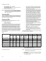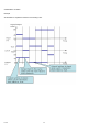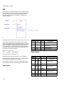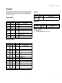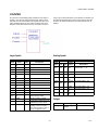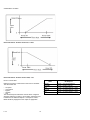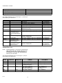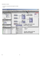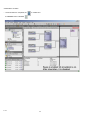
1
Honeywell Spyder
USER'S GUIDE
HONEYWELL SPYDER
Contents
About Honeywell Spyder Tool
.................................................................................................................................. 5
Scenarios
.................................................................................................................................. 5
Getting Started
.................................................................................................................................. 6
Creating Custom Palette File
.................................................................................................................................. 7
Programming Honeywell Spyder
.................................................................................................................................. 9
Views
.................................................................................................................................. 10
Controller Alarms View
.................................................................................................................................. 10
ControlProgram Details View
.................................................................................................................................. 11
Controller Summary View
.................................................................................................................................. 11
ControlProgram NV Configuration View ................................................................................................................................ 11
ControlProgram Wiresheet View
.................................................................................................................................. 12
ControlProgram Resource Usage View ................................................................................................................................. 13
ControlProgram Terminal Assignment View ......................................................................................................................... 13
Macro Details View
.................................................................................................................................. 14
Macro Resource Usage View
.................................................................................................................................. 14
Macro Wiresheet View
.................................................................................................................................. 14
Application Details View
.................................................................................................................................. 14
Application Programming View
.................................................................................................................................. 15
Application Resource Usage View
.................................................................................................................................. 15
Application NV Configuration View
.................................................................................................................................. 15
physical points
.................................................................................................................................. 17
Binary Inputs
.................................................................................................................................. 17
Binary Outputs
.................................................................................................................................. 19
Modulating Inputs
.................................................................................................................................. 21
Modulating Outputs
.................................................................................................................................. 23
Editing Software Points
.................................................................................................................................. 25
Software Inputs
.................................................................................................................................. 30
Software Outputs
.................................................................................................................................. 34
Network Variables
.................................................................................................................................. 35
Network Variable Input
.................................................................................................................................. 36
Network Configuration Input
.................................................................................................................................. 39
Many To One NV
.................................................................................................................................. 42
Network Variable Output
.................................................................................................................................. 43
Edit Network Variables
.................................................................................................................................. 47
63-2662
xx-xxxx
2
HONEYWELL SPYDER
Bindings
.................................................................................................................................. 51
Function Blocks
.................................................................................................................................. 52
Analog Function Blocks
.................................................................................................................................. 53
Analog Latch
.................................................................................................................................. 54
Average
.................................................................................................................................. 56
Compare
.................................................................................................................................. 57
Encode
.................................................................................................................................. 59
Hysteretic Relay
.................................................................................................................................. 62
MAXIMUM
.................................................................................................................................. 63
MINIMUM
.................................................................................................................................. 64
Priority Select
.................................................................................................................................. 65
Select
.................................................................................................................................. 67
Switch
.................................................................................................................................. 69
Built In Function Blocks
.................................................................................................................................. 71
Schedule
.................................................................................................................................. 72
Wall Module
.................................................................................................................................. 74
Control
.................................................................................................................................. 78
AIA
.................................................................................................................................. 79
Cycler
.................................................................................................................................. 81
Flow Control
.................................................................................................................................. 85
PID
.................................................................................................................................. 87
Rate Limit
.................................................................................................................................. 90
Stager
.................................................................................................................................. 92
Stage Driver
.................................................................................................................................. 95
Data Function Blocks
.................................................................................................................................. 98
Alarm
.................................................................................................................................. 99
Counter
.................................................................................................................................. 102
Override
.................................................................................................................................. 104
Runtime Accumulate
.................................................................................................................................. 105
Logic Function Blocks
.................................................................................................................................. 107
AND
.................................................................................................................................. 108
Oneshot
.................................................................................................................................. 110
OR
.................................................................................................................................. 112
XOR
.................................................................................................................................. 113
Math Function Blocks
.................................................................................................................................. 114
3
63-2662
xx-xxxx
HONEYWELL SPYDER
Add
.................................................................................................................................. 115
Digital Filter
.................................................................................................................................. 116
Divide
.................................................................................................................................. 118
Enthalpy
.................................................................................................................................. 119
Exponential
.................................................................................................................................. 120
Flow Velocity
.................................................................................................................................. 121
Limit
.................................................................................................................................. 123
Multiply
.................................................................................................................................. 124
Ratio
.................................................................................................................................. 125
Reset
.................................................................................................................................. 128
Square Root
.................................................................................................................................. 130
Subtract
.................................................................................................................................. 131
Zone ARBITRATION Function Blocks .................................................................................................................................. 132
General Set Point Calculator
.................................................................................................................................. 133
Occupancy Arbitrator
.................................................................................................................................. 136
Set Temperature Mode
.................................................................................................................................. 141
Temperature Set Point Calculator
.................................................................................................................................. 145
Calibrate flow
.................................................................................................................................. 151
Calibrate sensors
.................................................................................................................................. 153
Diagnostics
.................................................................................................................................. 154
Macros
.................................................................................................................................. 155
Library
.................................................................................................................................. 156
About Spyder Library
.................................................................................................................................. 156
Open Library
.................................................................................................................................. 158
Add Items to spyder Library
.................................................................................................................................. 159
Saving Library Items
.................................................................................................................................. 160
Load Library Item
.................................................................................................................................. 162
Delete Library items
.................................................................................................................................. 164
Export Library Items
.................................................................................................................................. 165
Import items to Library
.................................................................................................................................. 166
Order Of Execution
.................................................................................................................................. 167
Modes of Operation
.................................................................................................................................. 168
Engineering Mode
.................................................................................................................................. 169
Online Debugging Mode
.................................................................................................................................. 170
Select Points to Debug
.................................................................................................................................. 172
xx-xxxx
63-2662
4
HONEYWELL SPYDER
Force vALUES
.................................................................................................................................. 173
Simulation
.................................................................................................................................. 190
Simulation Setup
.................................................................................................................................. 210
Force Values
.................................................................................................................................. 212
Select Points to Display in Simulation Log Window ............................................................................................................ 214
Generate XIF File
.................................................................................................................................. 216
5
63-2662
xx-xxxx
HONEYWELL SPYDER
ABOUT HONEYWELL SPYDER TOOL
SCENARIOS
Honeywell Spyder Tool is an add-on module to the existing
Niagara framework modules. It provides a graphical
environment to program Honeywell Spyder Controllers. This
document serves as a guide to configure and use the
Honeywell Spyder Tool.
The Honeywell Spyder Tool provides the programming
environment for the Honeywell Spyder controllers. The
Honeywell Spyder controller is programmable controller and is
provided with a graphical environment to program it.
Abbreviations
• JACE: Java Application Control Engine
• NRE: Niagara Runtime Environment
It is developed with using Niagara AX framework developed
by Tridium and runs in the Niagara Runtime environment.
Domain Dictionary
The Honeywell Spyder Tool connects the Honeywell Spyder
controller in two ways:
1.
2.
3.
4.
5.
6.
7.
8.
9.
10.
JACE: Java Application Control Engine. The Tridiummanufactured controller that runs the core runtime Niagara software in a JVM, providing a station with the
direct support for field device integration and enterprise
LAN connectivity.
Fox: This is Tridium’s proprietary protocol for communication between workbench and the station.
Host: The host is a hardware platform or computer on
which the Niagara software runs. Niagara can run on a
computer or a JACE controller.
Station: The Niagara station is a JVM that hosts the running of objects.
Commission: This is the process of downloading the
application (program logic + network image) to the Honeywell Spyder controller.
Functional blocks: Functional blocks are the atomic program objects that define a specific function.
Macros: Macros are a set of functional blocks that
define a specific functionality.
Wiresheet: Wiresheet is the view in the Niagara workbench that allows you to drag and drop functional blocks
and macros to define application logic.
Programming environment/Graphical environment: A
wiresheet view that allows you to define your application
logic for the Honeywell Spyder controller.
Application: An Application is a group of function blocks
that are interconnected to form control logic. This application is then downloaded to the controller to run the
control logic in the controller.
• Through JACE
JACE (Java Application Control Engine) controller bundles the
software capability of the framework in a hardware platform.
JACEs connect to system field buses on the other end and
provide real time control functions. Honeywell Spyder Tool can
be hosted on a computer loaded with Niagara AX framework
as well as JACE. JACE is loaded with the framework, the
station database, and all the modules available in the
computer. The Honeywell Spyder Tool communicates with the
Honeywell Spyder controller through JACE. JACE is
connected to the same LAN as the PC and communicates to
the Honeywell Spyder Tool on Fox Protocol (on LAN). On the
other end, it communicates to the Honeywell Spyder controller
on the Lon bus.
The workbench in the computer also communicates with the
JACE by dialing into the onboard modem of the JACE.
However, this can be a slow connection.
• Through Engineering computer
In this case, the Niagara AX framework runs on the computer.
The computer connects to the system field buses directly
through the appropriate network interface. This is the
softJACE option.
The Honeywell Spyder Tool can be hosted on a computer
loaded with Niagara AX framework. The station database
resides on the same computer and connects to the Honeywell
Spyder controller on the Lon Network using the PCLTA/
PCMCIA card or through SLTA.
Station databases are typically engineered on the engineering
computer (this is called Offline Mode), then installed to a
JACE and its associated Web Supervisor computer, if any.
xx-xxxx
63-2662
6
HONEYWELL SPYDER
GETTING STARTED
Installation
1.
Install the.Jar file supplied by Honeywell on the target folder.
Drive:\\Niagara\Niagara-3.1.29\Modules
2.
Launching the Workbench
3.
• Click Start > Programs > Niagara > Workbench to launch
the workbench.
Adding New Station
On the Workbench:
1.
2.
3.
4.
5.
6.
6.
Click Tools > New Station. The New Station Wizard
appears.
Enter the Station Name.
The Station Directory path is updated with the name
you just entered and displays the location where the
files are stored. Click Next.
Enter a password in the Admin Password field.
Re-enter the same password in the Admin Password
Confirm field.
Click Finish to complete adding a station. The station is
added and the Property Sheet of the station is displayed on the right portion of your screen.
Starting the Station
On the Nav palette, click Platform. The Authentication
dialog box appears.
NOTE: If the Nav palette is not visible on the left pane, from
the Menu bar, select Window > Sidebars > Nav to
display the Nav palette.
2.
3.
4.
5.
6.
7.
7.
Adding a Controller
To add an Honeywell Spyder controller:
1.
2.
3.
4.
Once you have added a station, you must start it to begin
using it. To start a station:
1.
4.
5.
Enter User Name, Password, and click OK.
The Nav Container View appears on the right portion of
your screen with a list of object names and their
description.
Double-click Station Director. The list of available stations appears.
Select the station you have added and click Start. The
station you have added appears in the Nav palette
under Platform.
Double-click the Station option on the Nav palette. The
Authentication dialog box appears.
Enter User Name and Password and click OK. The
Station you have added is launched and the Station
Summary Property view appears on the right portion of
your screen.
Adding Lon Network
Click the Browse button on the Palette. The Open Palette dialog box appears.
Select HoneywellSpyder from the list and click OK or
click Browse and select the location where this folder is
stored and click OK.
Select LonSpyder from the Palette and drag and drop it
on Lon Network under Drivers in the Nav palette
Enter a name for the device you are adding and click
OK. The LonSpyderdevice is added.
Viewing/Modifying Controller Summary Details
To view/modify the summary details of the controller:
1.
2.
3.
—
—
—
—
Double-click the device name in the Nav palette to display the Controller Summary View on the right portion
of your screen.
Modify the Device Name.
Select Enable Daylight Savings option and specify the
following information when the day light savings must
come into effect:
Start Month
End Month
Start Day
End Day
Updating Modules
Follow this procedure to install updates of Standard
Applications. This is the StandardApps.jar file you will receive
that you will need to install to begin using the latest Standard
Applications provided.
1.
2.
To add a Lon Network:
3.
4.
7
Click Window > Side Bars > Palette to add the palette
named Palette if it is not visible on the bottom left portion of your screen.
Click the Browse button on the palette. The Open Palette dialog box appears.
Select Lonworks from the list if available and click OK
or click Browse and select the location where this folder
is stored and click OK.
Expand Config in the Nav palette to display Drivers.
Select LonNetwork from the Palette and drag and drop
it on Drivers in the Nav palette.
Enter a name for the Lon Network you are adding and
click OK.
Expand Drivers and verify to see that the Lon Network
is added.
Connect to the station’s platform.
Navigate to File transfer Client and transfer the StandardApps.jar file from the local drive to the Station’s
modules folder.
Restart the workbench/webworkbench.
Expand StandardApplications in the Spyder palette.
The latest Standard Applications are displayed.
63-2662
xx-xxxx
HONEYWELL SPYDER
CREATING CUSTOM PALETTE FILE
Create and use a custom palette file to store any Spyder
object application, macro, device, FBs, IOs from a station. You
can use this file to share it across Stations and among multiple
users. This custom palette file acts only as a repository but
you can not configure an object that exists in the palette.
You can later copy and paste or drag and drop these objects
from the custom palette to the station.
Creating a Custom Palette File
4.
5.
6.
To create a custom palette file:
1.
2.
3.
4.
5.
6.
7.
8.
9.
On the Nav palette, navigate to the drive where you
want to create the custom palette file. Right click the
drive and select New Folder. A new folder is created.
Enter a name for the new folder and click OK.
Right click the new folder and select New > Palettefile.palette
Enter a name for the palette file and click OK. A new
palette file is created. Expand the newly created folder
to view the palette file that you just now created.
Double click the alette folder to open its wiresheet.
On the Palette sidebar, click the Open Folder button.
The Open Palette dialog box appears.
Select Baja module and click OK. You will see the
UnrestrictedFolder highlighted in the Spyder palette.
Drag and drop the unrestricted folder on to the
wiresheet of the palette file that is currently open on the
right pane.
Enter a name for the folder and click OK. This is the
Unrestricted folder where you can store all Spyder
objects.
NOTE: You can double click the folder on the wiresheet and
drag and drop the UnrestrictedFolder object from the
Palette sidebar on to the wiresheet. This has the
effect of nesting folders within the palette file. This
enables you to categorize objects that are stored in
the palette file. For example, you can drag and drop
an UnrestrictedFolder from the Spyder palette on to
the wiresheet of the palette file and name it Applications. You can then double click the Applications
folder on the wiresheet and drag and drop another
UnrestrictedFolder object from the Spyder palette
and name it VAV Applications. This creates the VAV
Applications folder under the Applications folder in
a tree structure in the custom palette file you are creating.
Adding Items to the Custom Palette
To add any Spyder object such as a macro, application, IO,
Function block to the custom palette:
1.
2.
3.
63-2662
xx-xxxx
Navigate to the controlprogram you want to save in the
custom palette file by clicking Station > Drivers > LonNetwork > LonSpyder > ControlProgram in the Nav
palette.
Right click any Spyder object such as application,
macro, device, FB, or IO and select Copy.
Navigate to the folder you created under the custom
palette file ( Applications or VAV Applications as
given in the Note) and right click it and select Paste.
8
or
drag and drop the object to the wiresheet of the folder
(Applications or VAV Applications in the Note) under
the custom palette file
or
drag and drop a Spyder object directly on to the folder
(Applications or VAV Applications in the Note) under
the custom palette file in the Nav palette.
The object is saved under the folder in the custom palette file.
Right click the file in the custom palette file and click
Save.
Right click the custom palette file and click Close to
close the custom palette file.
Closing Palette File
To close the custom palette file, right click the custom palette
file and click Close.
NOTE: If you close a custom palette file without saving the
contents of the custom palette file or close the Workbench without saving the contents of the custom palette file, the newly added contents are not saved and
will not be available when you access this folder the
next time.
You can reuse components from the custom palette file in any
application logic you create by dragging and dropping the
desired object from the custom palette file to the wiresheet of
the ControlProgram.
Adding a Device to the Custom Palette File
Adding a device to the custom plaette file is similar to adding a
Spyder object but it has some specific steps you have to
perform additionally. To add a device to the Custom palette
file:
1.
2.
3.
4.
5.
Navigate to the device you want to save in the custom
palette file by clicking Station > Drivers > LonNetwork
> LonSpyder in the Nav palette.
Double click the ControlProgram under the device
once. It opens the wire sheet of the ControlProgram.
This makes sure that ControlProgram is loaded (all
device objects are available in memory while copying).
Right click the device and select Copy.
Navigate to the folder you created under the custom
palette file (Applications or VAV Applications as given
in the Note) and right click it and select Paste.
Right click the device and select Enable Saving Control Program.
Note: The Enable Saving ControlProgram option
makes the ControlProgram under device non-transient
so that it can be saved to the bog file. If this option is not
invoked or before invoking this option, you close the bog
file or the workbench, device looses the ControlProgram
configuration in the custom palette file. This option
appears on device only when device is in the custom
palette and ControlProgram under device is transient.
Once you invoke the option, the next time onwards the
same device option does not appear on the that particular device object. This option appears only when
required. If it does not appear, it means the ControlProgram of the device is already in a non-transient state.
This may happen when copy-pasting/duplicating a
HONEYWELL SPYDER
6.
saved device within/across palettes occurs or when you
copy-paste device object from the Spyder library to the
custom palette folder.
Right click the device and select Save. The device is
saved under the folder in the custom palette file.
9
xx-xxxx
63-2662
HONEYWELL SPYDER
PROGRAMMING HONEYWELL SPYDER
The Honeywell Spyder Tool offers a graphical environment to
program the Honeywell Spyder controller. You can use the
wiresheet view in the Engineering Mode to use Physical
points, NVs, and function blocks to build ControlProgram. The
Physical points, NVs, and function blocks can be accessed
using the Palette. You can drag and drop these items on to the
wiresheet and connect them, based on your need, to develop
your application logic. The logic that you create can then be
stored in a Spyder Library for reuse. Once you are satisfied
with the logic you have created, you can download the same
to the controller. Logic thus created can be tested for
correctness using the Simulation and Online Debugging
modes.
NOTE: Changing NCI values, configuration of a Schedule
block, or Daylight savings option, does not put the
application in a modified state. As long as the application has been downloaded atleast once to the controller, these changes only trigger a quick download
to the controller.
Use the ControlProgram option to program the Honeywell
Spyder tool. To do this:
1.
Expand LonSpyder in the Nav palette and double-click
ControlProgram to display the Wiresheet view.
2. Display the Palette (From the Menu bar, select Window
> Sidebars > Palette to display the Palette). The Palette appears on the left pane with the following items:
— LonSpyder: This is a device that you can drag and
drop on to the LonNetwork in the Nav palette to create
a new device.
NOTE: You cannot drop this on to the wiresheet of any
macro/ControlProgram/Program
—
Physical Points: Modulating and Binary Inputs/Outputs.
— SoftwarePoints: Software Input/Output. Use this to
create NVI, NCI, NVO, or constants.
— Analog: Analog function blocks
— Logic: Logic function blocks
— Math: Math function blocks
— Control: Control function blocks
— DataFunction: Data Function function blocks
— ZoneArbitration: Zone Arbitration function blocks
— BuiltIn: BuiltIn function blocks
— Macro: A Macro is a group of functional blocks
grouped together that define a specific functionality.
Commonly used program elements can be defined as
macros so that they could be reused across applications.
— Program: This includes macros and logic that you can
define and use in applications.
— StandardApplications: Standard applications
shipped by Honeywell which you can use to build
application logic
You can drag and drop any of these items on to the wiresheet
of an ControlProgram in its Engineering Mode and make the
connections between Physical points, NVs, and function
blocks to create macros/Program/ControlProgram.
63-2662
xx-xxxx
10
Use this wiresheet view to drag and drop Physical points and
Function blocks to build your application logic. You can save a
logic you created to be used later and also share it with other
users.You can build several applications and store them in a
Spyder Library along with Honeywell supplied standard
applications.
HONEYWELL SPYDER
VIEWS
CONTROLLER ALARMS VIEW
nvoError
This view displays all the alarms generated by the Honeywell
Spyder controller. There are 4 categories of alarms:
• Sensor Alarms: These alarms are generated for all the
Sensors configured in the logic. All input blocks assigned
to pins UI0 to UI7 will be listed in this category.
• Invalid ConfigurationAlarms: This alarm will occur if
there is an error in the configuration that was downloaded.
• Network Communication Alarms: These alarms will
occur ONLY for Network variable inputs (NVIs) configured
as fail detect. The network variable names will be listed in
this category.
• Control Alarms: All the alarm blocks configured in the
logic will be listed in this category. If an alarm block does
not have any incoming link then the status will always be
NORMAL.
To view the Alarms View of a controller, right-click the Device
Name in the Nav palette and select Views > Alarms View.
The Alarms view is displayed on the right half of the screen.
The Alarms view is static and you must refresh the view to get
the latest update.
This view displays all the alarms generated by the Honeywell
Spyder controller. There are 4 categories of alarms:
• Sensor Alarms: These alarms are generated for all the
Sensors configured in the logic. All input blocks assigned
to pins UI0 to UI6 will be listed in this category.
• Invalid ConfigurationAlarms: This alarm will occur if
there is an error in the configuration that was downloaded.
• Network Communication Alarms: These alarms will
occur ONLY for Network variable inputs (NVIs) configured
as fail detect. The network variable names will be listed in
this category.
• Control Alarms: All the alarm blocks configured in the
logic will be listed in this category. If an alarm block does
not have any incoming link then the status will always be
NORMAL.
To view the Alarms View of a controller, right-click the Device
Name in the Nav palette and select Views > Alarms View.
The Alarms view is displayed on the right half of the screen.
The Alarms view is static and you must refresh the view to get
the latest update.
The Honeywell Spyder tool provides a multi-byte network
variable, nvoError, which indicates errors. You can access the
nvoError map on the Property Sheet view of the controller.
The nvoError map consists of 10 fields of one byte each. As
each byte is 8 bits long, there are a maximum of 80 bits that
are used to indicate errors. Each bit is mapped to an alarm.
There are 4 categories of alarms:
• Sensor Alarms: These alarms are generated for all sensors
configured in the logic. All input blocks assigned to pins
UI0 to UI6 will be listed in this category.
• Invalid Configuration Alarms: This alarm occurs if there is
an error in the configuration that was downloaded.
• Network Communication Alarms: These alarms will occur
ONLY for Network variable inputs (NVIs) configured as fail
detect. The network variable names will be listed in this
category. You may define upto 32 input network variables
with fail detect. On detection of an alarm condition,
Honeywell Spyder fills a number between 16 and 47. It is
not neccessary that the bit position 16 is filled and then 17
and so on. Honeywell Spyder allocates any bit position
between 16 and 47. this sentence is conflicting the last
sentence in this document
• Control Alarms: All the alarm blocks configured in the logic
will be listed in this category. If an alarm block does not
have any incoming link then the status will always be
NORMAL. You may define upto 32 alarm function blocks.
On detection of an alarm condition, Honeywell Spyder fills
a number between 48 and 79. It is not neccessary that the
bit position 48 is filled and then 49 and so on. Honeywell
Spyder allocates any bit position between 48 and 79. this
sentence is conflicting the last sentence in this document
To view the Alarms View of a controller, right-click the Device
Name in the Nav palette and select Views > Alarms View. The
Alarms view is displayed on the right half of the screen. The
Alarms view is static and you must refresh the view to get the
latest update.
The following table indicates the bit positions and the alarms
they are used to represent:
0-7
Sensor Alarm
Indicates error condition on Modulating inputs
or outputs.
0
Sensor Alarm
The on-board pressure sensor is open or
shorted.
1
Sensor Alarm
Universal Input 1 exceeds the user defined
range, that is, it is open or shorted.
2
Sensor Alarm
Universal Input 2 exceeds the user defined
range
3
Sensor Alarm
Universal Input 3 exceeds the user defined
range
4
Sensor Alarm
Universal Input 4 exceeds the user defined
range
11
63-2662
xx-xxxx
HONEYWELL SPYDER
5
Sensor Alarm
Universal Input 5 exceeds the user defined
range
6
Sensor Alarm
Universal Input 6 exceeds the user defined
range
7
Sensor Alarm
Universal Input 7 exceeds the user defined
range
8-14
No mapping
The on-board thermistor is open or shorted
15
Invalid Configuration Alarm
The configuration downloaded to the controller
is illegal. One or more file sections have a
CRC error
16-47
Network Communication Alarm
The input network variable represented by this
bit is not being received within the fail detect
time.
48-79
Control Alarm
The alarm function block reporting the alarm
represented by this bit.
NOTE: UI 0 is diplayed only for models that support UI 0. UI
7 is not shown on the Alarms View.
CONTROLPROGRAM DETAILS VIEW
This view provides details of the ControlProgram, Application
or the Macro for which it is selected. It displays details such as
the Name, Version number, and a brief description.
To access the Details View of the controller:
1.
On the Nav palette, browse to Station > Config > Drivers > LonNetwork > LonSpyder.
2. Right click ControlProgram and select Views > Details.
The following fields appear:
— Name: The name you specified for the ControlProgram while creating it. It is non editable.
— Type: Indicates the air conditioning type used. You
can select General, CVAHU, or VAV as options.
NOTE: Exercise caution while changing the Type as it could
modify the application.
—
—
Version: The version number
Description: A brief description of the application.
Use this field to briefly describe the purpose of this
ControlProgram.
Use this view to view/modify Device Name, Device Model,
and select the period when day light savings are in effect. To
view/modify the summary details of the controller:
2.
3.
63-2662
xx-xxxx
4.
—
—
—
—
Select the Enable Daylight Savings option and specify
the following information when the day light savings
must come into effect:
Start Month
End Month
Start Day
End Day
NOTE: You must unselect the Day Light Savings option and
download it to the controller, for the controller to stop
using daylight savings.
5.
Click Save to save the changes or Reset to revert to the
previous settings.
CONTROLPROGRAM NV
CONFIGURATION VIEW
A Network Variable (NV) is a data item such as a temperature,
a switch value or actuator state. NVs can be thought of simply
as point parameters. LonMark functional profiles define
Standard Network Variable Types (SNVTs), but additional
non-standard NVs are usually available, depending on the
device, to store additional non-standard data.
CONTROLLER SUMMARY VIEW
1.
NOTE: You are free to select any model even if the application created does not fit the memory requirements of
the target model. Honeywell Spyder performs necessary actions on model change and give a report of
the same.
Double-click the device name in the Nav palette to display the Controller Summary View on the right of your
screen.
Modify the Device Name.
Select a Device Model.
12
There are three categories of NVs that the Lon Spyder
supports. They are:
• Mandatory: Mandatory NVs are the default NVs
mandatorily present in a Lon Spyder device.
• Fixed: You can use Fixed Dropable NVs while creating an
application logic but can edit only its Internal Data Type.
You can also display Fixed Dropable NVs on the wiresheet.
• Custom: Custom NVs are the NVs you create while
creating an application logic. They can be created, edited,
and deleted based on your requirements.
The Lon Spyder provides the following four built-in functions
that enable you to connect function blocks with other function
blocks.
HONEYWELL SPYDER
• NVI - Network Variable Inputs
• NVO - Network Variable Output
• NCI - Network Configuration Input
• Many to One NV - Many to One Network Variable
The Lon Spyder provides built-in functions, Network Variable
Inputs, to allow the selection of variables that are available
from/to the network. The configured network variables are
mapped to the Function Block memory space to be used by
any Function Block. Each Network variable may be configured
with a name.
—
If one or more selected points belong to a Many to
One NV.
—
If one or more selected points is configured as Bit
field .
—
If you select an input point and an output point.
—
If the point belongs to nciTempSetpoints
See the Add NVI, Add NCI, Add NVO, or Add Many to One
NV topics for more details.
NOTE:
—
Viewing the List of Network Variables
1.
Browse to Station > Config > Drivers > LonNetwork >
LonSpyder.
2. Select ControlProgram > Views > NV Configuration
View. The summary page appears with a list of pre-programmed Mandatory, Fixed, and Custom NVs in a
tabular format.
The table has the following columns:
—
—
• NV Name: The name of the network variable.
• Type: Indicates if the NV is of type NVI, NVO, NCI or Many
to One NV.
• Category: Indicates if the NV is Mandatory, Fixed, or
Custom.
• NV Container: Indicates where the NV is used.
3. The bottom half of the NV Configuration view displays
the software points available on the wiresheet in a tabular format.
The table has the following columns:
—
—
—
—
—
—
—
• Point Name: The name of the software point (Software
Input/Software Output) as it appears on the wiresheet.
• Field Names: Indicates if the NV is of type NVI, NVO, NCI
or Many to One NV.
• Point Container: Indicates where the software point is
used. All software points that are used in a Program within
an application are also listed.
NOTE:
—
—
—
—
—
—
Mandatory NVscannot be used in the application
logic.
Mandatory NVs cannot be edited or deleted.
In a Fixed NV, only Internal Data Type can be
modified.
Custom NV is the user defined NV. A Custom NV
can be edited or deleted.
Fixed NVs marked as Fixed_Dropable can be
exposed on the wiresheet. Other fixed NVs cannot be exposed as points.
For each point that is copied and pasted on the
wiresheet, a new NV of SNVT type nearest to the
selected datatype is created automatically.
Group as NV
CONTROLPROGRAM WIRESHEET
VIEW
The Wiresheet View is that screen/view of the Honeywell
SpyderTool interface that you use to engineer the tool.
Function blocks, Physical points, and NVs are the building
blocks of the logic you can create and download to the
Honeywell Spyder controller.
You can create and build your own logic using function blocks
or create ControlProgram and libraries or macros, using the
Wiresheet view. On this view, you can drag and drop function
blocks, Physical points, and NVs that you use to build and
define logic. This logic then forms a part of the macros and
Spyder libraries that you want to save and reuse.
NOTE: Names of Physical points must be unique. No two
Physical points can have the same name.
To view the Wiresheet View for the following:
You can group points belonging to types NVI, NCI, NVO,
Constants, and Invalid points to form a new NVI, NCI, or NVO.
NOTE: Use the CTRL key to select multiple points to group.
This button is disabled in the following cases:
—
Mandatory NVscannot be used in the application
logic.
Mandatory NVs cannot be edited or deleted.
In a Fixed NV, only Internal Data Type can be
modified.
Custom NV is the user defined NV. A Custom NV
can be edited or deleted.
Fixed NVs marked as Fixed_Dropable can be
exposed on the wiresheet. Other fixed NVs cannot be exposed as points.
Software Input with Point Type configured as
Constant in a macro are not shown in the lower
pane of the NV Configuration View.
For each point that is copied and pasted on the
wiresheet:
If the network type is a scalar SNVT, the new NV
created is SNVT of the network type.
If the network type is a Bit field, the new NV of
SNVT type nearest to the selected internal data
type is created automatically.
In all other cases, a single-field UNVT with the
same configuration as the point being copied is
created.
If one or more selected points belong to a Fixed
NV.
13
1.
2.
3.
On the Nav palette, browse to Station > Config > Drivers
> Lon Network > LonSpyder.
Expand LonSpyder and select ControlProgram.
Right-click ControlProgram and select Views >
Wiresheet. The wiresheet is displayed on the right of the
screen in the Engineering mode. The Wiresheet View
consists of a wiresheet like appearance on the right
pane. You can drag and drop function blocks, Physical
points, and NVs on to this wiresheet and make the con63-2662
xx-xxxx
HONEYWELL SPYDER
nections to and from Physical points and function blocks
to build your logic on the wiresheet. It also consists of
fixed Physical points. It also consists of a snapshot view
of the entire wiresheet page on the top right corner. This
helps you to have an overview of the entire sheet in
cases where you have many function blocks/Physical
points and so on.
4.
5.
6.
NOTE: All the Fixed Physical points are visible on the ControlProgram Wiresheet view of the Controller
7.
Designing The Application Logic
8.
Follow these steps for designing your application:
1.
2.
3.
4.
5.
6.
7.
8.
9.
Decide the Physical points
Develop Sequence
Decide the interface requirements for the open Lon connection or with other Lon devices
Develop software logic using modules or import the
modules that you want to use
Interconnect Physical point to other modules and to the
outside connections
Test the logic through simulation
Correct any changes to the design or modifications to
the Macros
Save Macros that you would want to reuse in a library
Save your device in a library if you want to be able to
reuse it here or on other projects
CONTROLPROGRAM RESOURCE
USAGE VIEW
The ControlProgram, Spyder libraries and macros you create
consume memory. The function blocks, Physical points and
NVs have different memory usage. Some elements of a
function block may use a Float RAM while some others could
be using memory in the Non-Volatile RAM.
The Resource Usage View provides details of the total
memory and the used memory as a result of all the
ControlProgram, Spyder libraries and macros you create.
Name
Name of the Function block, IO, or NV.
Type
Indicates the type of the Function block, IO, or
NV.
Float RAM Indicates the Float RAM usage of the Function
block, IO, or NV.
Byte RAM Indicates the Byte RAM usage of the Function
block, IO, or NV.
Flash
Indicates the Flash memory usage of the
Function block, IO, or NV.
NV RAM
Indicates the NV RAM usage of the Function
block, IO, or NV.
Valid
Indicates if the point is valid/inavlid.
Block
Indicates the location of the Function block, IO,
Container or NV.
9.
10.
ControlProgram Resource Usage
Application Resource Usage
Macro Resource Usage
Spyder library Resource Usage
11.
NOTE: At each of these levels the memory used up by
the entire application is shown.
ControlProgram Resource Usage
To view the Resource Usage View of the controller:
1.
2.
3.
xx-xxxx
63-2662
On the Nav palette, browse to Station > Config > Drivers > Lon Network > LonSpyder.
Expand LonSpyder and select ControlProgram.
Right-click ControlProgram and select Views >
Resource Usage. The Controller Details appear on
the right half of the screen.
14
Definition
Block
You can see the memory usage at different levels as
described:
•
•
•
•
You can select the Controller Model. This is model number or make of the controller that you are programming
using this tool.
The Memory Usage chart graphically displays a bar
chart of the total memory and used memory details.
You can click the Tabular View button to view the
breakup of RAM pool usage in a tabular format. Click
the Tabular View button to hide/display the tabular view.
The Blocks Usage table displays the number of Function blocks, Network variables, and IOs used at the
device level. IOs indicates the number of hardware pins
used.
Click the Memory Usage button to view details of the different memory types. The Block Memory Details tab displays memory usage details of the Function blocks,
NVs, and IOs used in the device in a tabular format.
Click the RAM Pool Usage Details tab to view the memory usage status of the controller. You can click the Tabular View button to view the breakup of RAM pool usage
details in a tabular format. Click the Tabular View button
to hide/display the tabular view.
Click the Validate button to find out the Error messages
and Warning messages, if any, in a new window. Typically you will find messages pertaining to warnings,
errors and detailed report of invalid points, IOs, excess
memory counters, excess NVs created, excess engineering units configured and so on. Click OK to close
the window.
Click Save if you have made any changes to the Controller Model for the changes to take effects.
CONTROLPROGRAM TERMINAL
ASSIGNMENT VIEW
This view provides a layout of the physical arrangement of the
pins on the controller. Use this view to view/modify the
configuration of inputs/outputs of the selected controller. You
can select which inputs/outputs must be assigned to:
•
•
•
•
Universal Inputs (UI) 1 to 6
Digital Inputs (DI) 1 to 4
Analog Outputs (AO) 1 to 3
Digital Outputs (DO) 1 to 8
HONEYWELL SPYDER
NOTE: UI 0 and UI 7 are not shown on the Terminal Assignment View.
The inputs/outputs you have used to build the application logic
are available as options for UI, DI, AO, and DO. You can
choose which of the inputs/outputs that you have used to build
the application logic will be assigned to the physical pins of
the controller.
Example
Let us say you have used four Modulating Inputs named
Modulating Input 1, Modulating Input 2, Modulating Input 3,
Modulating Input 4 and two Binary Inputs named BinaryInput
1 and BinaryInput2. On the Terminal Assignment View, for
each Universal Input (UI 0 to 7), you will have the option to
choose Modulating Inputs 1 to 4 or Binary Inputs 1 to 2.
Assign all the inputs and outputs and click Save to save the
details or Reset to revert to the last saved changes.
—
—
—
—
—
—
If you change the device model , the physical IOs
continue to retain the IO pins previously assigned
except in the following scenarios:
If a custom IO has been assigned a pin that is
fixed in the target model, HoneywellSpyder
assigns a free pin, if available. If no free pin is
available, the IO becomes an invalid IO.
If there was a fixed pin assigned to a fixed IO in
the source model and is different in the target
model, Honeywell Spyder reassigns the fixed pin
in the target model to that IO. But if the fixed pin is
already in use in the target model, Honeywell
Spyder converts the IO to the nearest custom
type and reassigns a valid pin available. If there is
no valid pin available the IO becomes unassigned.
If the target model supports less number of IOs
than the source model, Honeywell Spyder unassigns the pins for the IOs that are in excess in the
target model
If target model supports more number of IOs than
the source, Honeywell Spyder assigns available
free pins to any invalid IOs present.
A report of all actions taken is generated.
If the name of a custom NV clashes with a fixed
NV name in the target model, Honeywell Spyder
generates a new unique name for the custom NV
and creates the new fixed NV.
The Resource Usage View provides details of the total
memory and the used memory as a result of all the logic you
have used in creating the macro.
2.
3.
On the Nav palette, right click the Macro and select
Views > Resource Usage. The Resource Usage View
is displayed on the right of the screen.
The Memory Usage chart graphically displays a bar
chart of the total memory and used memory details.
The memory usage details of the different memory
types is also displayed in a tabular format.
MACRO WIRESHEET VIEW
To view the Macro wiresheet:
1.
2.
On the Nav palette, Palette palette or Macro Palette,
right click the Macro and select Views > Wiresheet.
The Wiresheet is displayed on the right of the screen.
Use this screen to build your logic using Physical points
and Function Blocks.
NOTE: If you drag and drop the macro from the Nav palette
on to the ControlProgram’s Wiresheet View, and
select the wiresheet for the macro, it will be empty.
However, If you drag and drop the macro from the
Macro Library palette on to the ControlProgram’s
Wiresheet View, and select the wiresheet for the
macro, it will have the function blocks you have created.
APPLICATION DETAILS VIEW
This view provides details of the Application. It displays details
such as the Name, Type, Version number, and a brief
description.
This view provides details of the Macro. It displays details
such as the Name, Type, Version number, and a brief
description.
To access the Details View of the Application:
To access the Details View of the macro:
2.
3.
The ControlProgram, Spyder libraries and macros you create
consume memory. The function blocks, Physical points and
NVs have different memory usage. Some elements of a
function block may use a Float RAM while some others could
be using Non-Volatile RAM.
1.
MACRO DETAILS VIEW
1.
MACRO RESOURCE USAGE VIEW
To view the Resource Usage View of the macro:
NOTE:
—
• Name: The name you specified for the Program while
creating it. It is non editable.
• Version: The version number. It is non editable.
• Description: A brief description of the macro. Use this field
to briefly describe the purpose of this macro.
1.
On the Nav palette, browse to Station > Config > Drivers > LonNetwork > LonSpyder.
Expand ControlProgram and right click Macro.
Select Views > Details. The following fields appear:
On the Nav palette, browse to Station > Config > Drivers > LonNetwork > LonSpyder.
2. Expand ControlProgram and right click Application.
3. Select Views > Details. The following fields appear:
• Name: The name you specified for the Program while
creating it. It is non editable.
15
63-2662
xx-xxxx
HONEYWELL SPYDER
• Type: Indicates the type used. You can select General,
CVAHU, or VAV as options.
4.
NOTE: Exercise caution while changing the Type as it could
modify the application.
5.
6.
• Version: The version number. It is non editable.
• Description: A brief description of the application. Use this
field to briefly describe the purpose of this Program.
The Controller Model is non editable. This is model
number or make of the controller that you are programming using this tool.
The Memory Usage chart graphically displays a bar
chart of the total memory and used memory details.
The memory usage details of the different memory
types is also displayed in a tabular format.
APPLICATION PROGRAMMING VIEW
APPLICATION NV CONFIGURATION
VIEW
The Wiresheet View for the Sub Application that screen/view
of the Honeywell SpyderTool interface that you use to
engineer the tool. You can create the Program by connecting
function blocks to software inputs/outputs and physical inputs/
outputs. To view the Application Wiresheet view of the
controller:
A Network Variable (NV) is a data item such as a temperature,
a switch value or actuator state. NVs can be thought of simply
as point parameters. LonMark functional profiles define
Standard Network Variable Types (SNVTs), but additional
non-standard NVs are usually available, depending on the
device, to store additional non-standard data.
1.
2.
3.
4.
On the Nav palette, browse to Station > Config > Drivers > Lon Network > LonSpyder.
Expand LonSpyder and select ControlProgram.
Expand the ControlProgram and right-click the Application whose wiresheet you want to view and select
Views > Wiresheet. The wiresheet is displayed on the
right of the screen.
Use this screen to build your Program using Physical
points and Function Blocks.
NOTE:
• If you drag and drop a Application from the Nav palette on
to the Wiresheet of an ControlProgram, Physical points are
not visible.
• If you drag and drop a Application from a library to the
ControlProgram’s Wiresheet View, Physical points are
visible in the wiresheet of the Program and not on the
parent Application Logic’s Wiresheet View.
• If you delete the Program, fixed Physical points appear in
the Wiresheet View of the ControlProgram.
APPLICATION RESOURCE USAGE
VIEW
The application logic, Spyder libraries and macros you create
consume memory. The function blocks, Physical points and
NVs have different memory usage. Some elements of a
function block may use a Float RAM while some others could
be using Non-Volatile RAM.
The Resource Usage View provides details of the total
memory and the used memory as a result of all the application
logic, Spyder libraries and macros you have used in creating
the Program.
To view the Resource Usage View of the Program:
1.
2.
3.
xx-xxxx
63-2662
On the Nav palette, browse to Station > Config > Drivers > Lon Network > LonSpyder.
Expand LonSpyder and expand ControlProgram.
Right-click ControlProgram and select Views >
Resource Usage. The Resource Details appear on
the right half of the screen.
16
There are three categories of NVs that the Lon Spyder
supports. They are:
• Mandatory: Mandatory NVs are the default NVs
mandatorily present in a Lon Spyder device.
• Fixed: You can use Fixed Dropable NVs while creating an
application logic but can edit only its Internal Data Type.
You can also display Fixed Dropable NVs on the wiresheet.
• Custom: Custom NVs are the NVs you create while
creating an application logic. They can be created, edited,
and deleted based on your requirements.
The Honeywell SpyderTool provides the following four built-in
functions that enable you to connect function blocks with other
function blocks.
• NVI: Network Variable Inputs
• NVO: Network Variable Output
• NCI: Network Configuration Input
• Many to One NV: Many to One Network Variable
The Honeywell SpyderTool provides built-in functions,
Network Variable Inputs, to allow the selection of variables
that are available from/to the network. The configured network
variables are mapped to the Function Block memory space to
be used by any Function Block. Each Network variable may
be configured with a name.
Viewing the List of Network Variables
1.
Browse to Station > Config > Drivers > LonNetwork >
LonSpyder.
2. Expand ControlProgram and right click Application
and select Views > NV Configuration View. The summary page appears with a list of NVs used in the Program appears.
The table has the following columns:
• NV Name: The name of the network variable.
• Type: Indicates if the NV is of type NVI, NVO, NCI or Many
to One NV.
• Category: Indicates if the NV is Mandatory, Fixed, or
Custom.
• Display on WireSheet: Indicates if the NV will be
displayed on the wiresheet or not.
3. The bottom half of the NV Configuration view displays
the software points available on the wiresheet in a tabular format.
The table has the following columns:
HONEYWELL SPYDER
• Point Name: The name of the software point (Software
Input/Software Output) as it appears on the wiresheet.
• Field Names: Indicates if the NV is of type NVI, NVO, NCI
or Many to One NV.
• Point Container: Indicates where the software point is
used.
—
—
Fixed NVs marked as Fixed_Dropable can be
exposed on the wiresheet. Other fixed NVs cannot be exposed as points.
For each point that is copied and pasted on the
wiresheet, a new NV of SNVT type nearest to the
selected datatype is created automatically.
NOTE: This screen displays only those NVs that are used in
this Application.
—
—
—
—
Mandatory NVs cannot be used in the application
logic.
Mandatory NVs cannot be edited or deleted.
In a Fixed NV, only Internal Data Type can be
modified.
Custom NV is the user defined NV. A Custom NV
can be edited or deleted.
17
xx-xxxx
63-2662
HONEYWELL SPYDER
PHYSICAL POINTS
Physical points are logical objects that are used in building
application logic. Depending on the model selected, default
(Fixed) Physical points, for that model, are made available.
NOTE:
—
Example: For the PVL6436A, you can configure Actuator and
On Board Pressure Sensor as fixed physical points.For the
PVL 6438N, you can only configure On Board Pressure
Sensor as a fixed physical point.
—
The Honeywell SpyderTool automatically validates rules,
based on the model selected.
The four types of Physical points available that you can
configure are:
•
•
•
•
Binary Inputs
Binary Outputs
Modulating Inputs
Modulating Outputs
—
BINARY INPUTS
A binary input is a physical input. You can configure Binary
Input blocks and use them while creating application logic.
NOTE: A binary input cannot be dropped under a macro.
To add and configure a binary input block:
1.
Right-click ControlProgram under Honeywell Spyder
in the Nav palette and select Views > Wiresheet View
to view the wiresheet.
Drag and drop the Binary Input block from the Spyder
Palette on to the wire sheet.
Enter the desired name for the Binary Input block and
click OK. The block appears as a container on the wire
sheet similar to any function block.
Right-click the container and select Configure Properties. The Binary Input dialog box appears. The following table defines the fields shown in the dialog box.
2.
3.
4.
Name
Description
Point Name Enter a name of the function block or use the
default names given by the tool.
Point Type
Binary Input is the default selection. You can
select Constant, Software Input, Binary
Input or Modulating Input to change the
point type.
Input State
Normally Open
Normally Closed
OK
Saves the entered information and closes the
dialog box.
Cancel
Closes the dialog box. Any information
entered is lost.
xx-xxxx
63-2662
18
You can drag and drop IOs on to the wiresheet
even when all pins are used up. Honeywell Spyder allows IOs to be dropped but they will not be
assigned with a pin. Such IOs are termed as
invalid IOs. A message indicating that the IO does
not get a pin is displayed.
When a physical IO (Modulating input, Binary
input, Modulating output, Binary output) with a
valid IO pin is copied and pasted in the wiresheet,
the resulting IO gets the same configuration as
the source and a new available pin. If no free pin
is available, the resulting IO becomes an invalid
IO.
When an invalid physical IO (Modulating input,
Binary input, Modulating output, Binary output) is
copied and pasted in the wiresheet, the resulting
IO gets the same configuration as the source and
it is also an invalid IO.
HONEYWELL SPYDER
Point Conversion
What do I convert
Binary Input
To what do I
convert?
Constant
How do I do it?
1.
2.
3.
Binary Input
NCI
1.
2.
3.
4.
5.
Binary Input
Software Input
(NVI)
1.
2.
3.
4.
5.
Binary Input
Modulating
Input
1.
2.
3.
4.
5.
What is the effect?
Right-click the Binary
input block and select
Configure Properties.
Select Constant from the
Point Type list.
Click OK.
1.
Right-click the Binary
input block and select
Configure Properties.
Select Constant from the
Point Type list.
Enter a Value.
Select Share Point on
Network.
Click OK.
1.
Right-click the Binary
input block and select
Configure Properties.
Select Software Input
from the Point Type list.
Select a Point Category.
Select Units to be used
within logic.
Click OK.
1.
Right-click the Binary
input block and select
Configure Properties.
Select Modulating Input
from the Point Type list.
Select Type.
Select Data Type.
Click OK.
1.
19
2.
2.
3.
2.
3.
2.
If the Binary Input was connected to a slot of
a function block, the slot is converted from
Connector type to Constant.
Any IO pins used by the Binary input are
freed.
The IO pins used by the Binary Input are
freed.
A new NCI of type Snvt is created, determined by the Point Category, Internal Data
Type unit selected.
The new NCI is seen in the NVs table in the
NV Configuration View.
The IO pins used by the Binary Input are
freed.
A new NVI of type Snvt is created, determined by the Point Category, Internal Data
Type unit selected.
The new NVI is seen in the NVs table in the
NV Configuration View.
If there are no IO pins available for the target
physical IO (in this case, the Modulating input
that is created), the point becomes an invalid
IO.
A warning message appears indicating that
there are no more pins to allocate, and an
unassigned IO is created.
xx-xxxx
63-2662
HONEYWELL SPYDER
BINARY OUTPUTS
—
A binary output is a physical output. You can configure Binary
Output blocks and use them while creating application logic.
To add and configure a binary output block:
1.
Right-click ControlProgram under LonSpyder in the
Nav palette and select Views > Wiresheet View to view
the wiresheet.
Drag and drop the Binary Output block from the Spyder Palette on to the wire sheet.
Enter the desired name for the Binary Output block and
click OK. The block appears as a container on the wire
sheet similar to any function block.
Right-click the container and select Configure Properties. The Binary Output dialog box appears. The following table defines the fields shown in the dialog box.
2.
3.
4.
Name
Description
Point Name Enter a name or use the default names given
by the tool.
Point Type
Binary Output is the default selection. You
can select Software Output or Modulating
Output to change the point type.
OK
Saves the entered information and closes the
dialog box.
Cancel
Closes the dialog box. Any information entered
is lost.
NOTE:
—
—
—
63-2662
xx-xxxx
You can drag and drop IOs on to the wiresheet
even when all pins are used up. Honeywell Spyder allows IOs to be dropped but they will not be
assigned with a pin. Such IOs are termed as
invalid IOs. A message indicating that the IO does
not get a pin is displayed.
When a binary output is deleted, if it had a valid
IO pin assigned, the freed pin is automatically
assigned to an invalid Modulating output configured as PWM type or to an invalid binary output, if
any.
When a physical IO (Modulating input, Binary
input, Modulating output, Binary output) with a
valid IO pin is copied and pasted in the wiresheet,
the resulting IO gets the same configuration as
the source and a new available pin. If no free pin
is available, the resulting IO becomes an invalid
IO.
20
When an invalid physical IO (Modulating input,
Binary input, Modulating output, Binary output) is
copied and pasted in the wiresheet, the resulting
IO gets the same configuration as the source and
it is also an invalid IO.
HONEYWELL SPYDER
Point Conversion
What do I want to
convert?
Binary Output
To what do I
want to
convert?
Software Output
(NVO)
How do I do it?
1.
2.
3.
4.
5.
Binary Output
Modulating
Output
1.
2.
3.
4.
5.
6.
What is the effect?
Right-click the Binary output block and select Configure Properties.
Select Software Output
from the Point Type list.
Select a Point Category.
Select Units to be used
within logic.
Click OK.
1.
Right-click the Binary output block and select Configure Properties.
Select Modulating Output from the Point Type
list.
Select Type.
Select Analog Type.
Select Output Values.
Click OK.
1.
21
2.
3.
4.
2.
The IO pins used by the Binary output are
freed.
A new NVO of type Snvt is created, determined by the Point Category, Internal Data
Type unit selected.
The new NVO is seen in the NVs table in the
NV Configuration View.
A new NV is created even if the NV count
exceeds the maximum number and a warning message appears indicating the same.
If there are no IO pins available for the target
physical IO (in this case, the Modulating output that is created), the point becomes an
invalid IO.
A warning message appears indicating that
there are no more pins to allocate, and an
unassigned IO is created.
63-2662
xx-xxxx
HONEYWELL SPYDER
MODULATING INPUTS
Input State
Use this to edit sensor characteristics. The
Input State is editable only when a custom
sensor (Custom Resistive or Custom
Voltage) is selected in the Type field. You can
enter values for:
• Input Low
• Input High
• Output Low
• Output High
Sensor
Limits
Click the Sensor button to view and set the
upper and lower limits.
• Enter a lower limit in the Low Limit field.
• Enter an upper limit in the High Limit field.
A modulating input is a physical input. You can configure
Modulating Input blocks and use them while creating
application logic.
To add and configure a Modulating Input block:
1.
Right-click ControlProgram under LonSpyder in the
Nav palette and select Views > Wiresheet View to view
the wiresheet.
Drag and drop the Modulating Input block from the
Spyder Palette on to the wire sheet.
Enter the desired name for the Modulating Input block
and click OK. The block appears as a container on the
wire sheet similar to any function block.
Right-click the container and select Configure Properties. The Modulating Input dialog box appears. The
following table defines the fields shown in the dialog
box.
2.
3.
4.
Name
Description
Point Name Enter a name of the function block or use the
default names provided by the tool.
Point Type
Modulating Input is the default selection. You
can select Constant, Binary Input or
Software Input if you want to change the
input type.
Type
Displays the list of sensors that can be
connected. Select a sensor type.
Data
Category
Displays the unit of measurement for the
Type. This is enabled when Custom
Resistive or Custom Voltage is selected in
the Type field.
Data Type
Sensor Readings Outside Limit
• Choose Value is INVALID outside High if
you want Invalid to be displayed when the
limits are crossed.
• Choose Clamp Value as High and Low
Limit if you want the Low and High Limits
that you enter to be displayed when the
limits are crossed.
OK
Saves the entered information and closes the
dialog box.
Cancel
Closes the dialog box. Any information
entered is lost.
NOTE:
—
—
Displays the engineering unit based on the
Data Category.
—
—
—
xx-xxxx
63-2662
22
You can drag and drop IOs on to the wiresheet even
when all pins are used up. Honeywell Spyder allows
IOs to be dropped but they will not be assigned with a
pin. Such IOs are termed as invalid IOs. A message
indicating that the IO does not get a pin is displayed.
When a modulating input is deleted, if it had a valid IO
pin assigned, the freed pin is automatically assigned
to any invalid modulating input or an invalid binary
input.
When a physical IO (Modulating input, Binary input,
Modulating output, Binary output) with a valid IO pin is
copied and pasted in the wiresheet, the resulting IO
gets the same configuration as the source and a new
available pin. If no free pin is available, the resulting IO
becomes an invalid IO.
When an invalid physical IO (Modulating input, Binary
input, Modulating output, Binary output) is copied and
pasted in the wiresheet, the resulting IO gets the same
configuration as the source and it is also an invalid IO.
When you copy and paste a modulating intput of type
standard and custom sensors on the wiresheet, the
same configuration is retained. Even though an On
Board Pressure Sensor can be configured, it will not
be as a consequence of the copy and paste action on
the wiresheet.
HONEYWELL SPYDER
Adding an Onboard Pressure Sensor
To add an Onboard Pressure Sensor:
The on-board pressure sensor is always assigned to the
Universal Input # 0, in case where the model supports this
fixed physical point, whether it is physically present or not.
1.
NOTE: The number of On Board Pressure Sensors you can
add are dependent on the Controller model selected.
If you exceed the allowed limit of On Board Pressure
Sensors in an application logic, you cannot configure
the modulating outputs as On Board Pressure Sensor.
3.
4.
2.
Example: To the PVL6436A, if you add more than six
modulating inputs in your logic, the seventh Modulating input
you add is automatically configured as an On Board Pressure
Sensor and is assigned to Pin0.
What do I want to
convert?
Modulating Input
To what do I
want to
convert?
Constant
3.
4.
5.
6.
NCI
1.
2.
3.
4.
5.
Modulating Input
Software Input
(NVI)
1.
2.
3.
4.
5.
Modulating Input
Binary Input
Point Conversion
How do I do it?
1.
2.
Modulating Input
Drag and drop a Modulating Input from the Spyder
Palette to the wiresheet.
Right click the Modulating Input you just added and
select Configure Properties.
Select On_Board_Pressure from the Type list.
Click OK to complete adding an On Board Pressure
Sensor.
1.
2.
3.
4.
5.
What is the effect?
Right-click the Modulating input block and select
Configure Properties.
Select Constant from the
Point Type list.
Select a Point Category.
Select Units to be used
within logic.
Select Value.
Click OK.
1.
Right-click the Modulating input block and select
Configure Properties.
Select Constant from the
Point Type list.
Enter a Value.
Select Share Point on
Network.
Click OK.
1.
Right-click the Modulating input block and select
Configure Properties.
Select Software Input
from the Point Type list.
Select a Point Category.
Select Units to be used
within logic.
Click OK.
1.
Right-click the Modulating input block and select
Configure Properties.
Select Binary Input from
the Point Type list.
Select Type.
Select Data Type.
Click OK.
1.
NOTE:
—
23
2.
2.
3.
2.
3.
2.
If the Modulating Input was connected to a
slot of a function block, the slot is converted
from Connector type to Constant.
IO pins used by the Modulating input are
freed.
The IO pins used by the Modulating input are
freed.
A new NCI of type Snvt is created, determined by the Point Category, Internal Data
Type unit selected.
The new NCI is seen in the NVs table in the
NV Configuration View.
The IO pins used by the Modulating input are
freed.
A new NVI of type Snvt is created, determined by the Point Category, Internal Data
Type unit selected.
The new NVI is seen in the NVs table in the
NV Configuration View.
If there are no IO pins available for the target
physical IO (in this case, the Binary input that
is created), the point becomes an invalid IO.
A warning message appears indicating that
there are no more pins to allocate, and an
unassigned IO is created.
When you copy and paste an On Board Pressure
Sensor (modulating intput) on the wiresheet such
that the maximum allowed count for that model is
exceeded, it is converted to a custom voltage sensor .
xx-xxxx
63-2662
HONEYWELL SPYDER
MODULATING OUTPUTS
You can configure Modulating Output blocks and use them
while creating application logic.
To add and configure a Modulating Output block:
1.
Right-click ControlProgram under LonSpyder in the
Nav palette and select Views > Wiresheet View to view
the wiresheet.
Drag and drop the Modulating Output block from the
Palette on to the wire sheet.
Enter a name for the Modulating Output block and click
OK. The block appears as a container on the wire sheet
similar to any function block.
Right-click the container and select Configure Properties. The Modulating Output dialog box appears. The
following table defines the fields shown in the dialog
box.
2.
3.
4.
Name
Description
Point Name Enter a name or use the default names
provided by the tool.
Point Type
Modulating Output is the default selection.
You can select Software Output or Binary
Output to change the point type.
Type
Indicates modulating output type. You can
select one of the following types:
• Analog: Use this option to drive the motor
fully opened or fully closed based on the
output values specified.
• Floating: Select this option if you want an
output that behaves as a digital output.
• Pwm: Select this option if you want an
output that behaves as a digital output.
• Actuator: Select this option if you want an
output as a fixed Physical point.
Analog
Type
This is enabled only when Analog is selected
in the Type field. You can select one of the
following:
• Volts: The range is 0-10 Vdc.
• Amps: The range is 4-20mA.
Output
Values
This is enabled only when Analog is selected
in the Type field. Enter the value for Zero
Percent and Full Percent.
NOTE: Each modulating output can be configured for the output voltage/current
at 0% and at 100%. Each Modulating
Output circuit operates in current
mode for loads up to 600 ohms. For
loads of 600 to 1000 ohms, the output
transitions to voltage mode. For loads
above 1000 ohms, the output operates in voltage. When full percent is
less than zero percent, the motor runs
in reverse direction.
63-2662
xx-xxxx
24
PWM
This is enabled when Pwm is selected in the
Configurati Type field. You can enter the values for the
on
following:
• Period: The range is between 1-3276.7
seconds in tenths of seconds.
• Zero time
• Full time
Floating
This is enabled when Floating is selected in
Motor
the type field.
Configurati • Travel time: Indicates the motor speed. It
on
can be configured from 0-3276.7 seconds in
tenths of seconds.
• AutoSyncType: You can select one of the
following values:
• None: Honeywell Spyder assumes the
motor is fully closed.
• Sync Open: The motor is driven fully open.
• Sync Closed: The motor is driven fully
closed.
• AutoSyncInterval: The Auto
Synchronization Interval is configured from
0 to 255 hours in one hour increments. The
timer is loaded and starts counting down
right after power up reset and power up
delay. When the timer expires, the motor is
synchronized. This only applies if the user
configured auto synchronization to be Sync
Open or Sync Closed.
• PowerupSyncType: You can select one of
the following values:
• None: Honeywell Spyder assumes the
motor is fully closed.
• Sync Open: The motor is driven fully open.
• Sync Closed: The motor is driven fully
closed.
• PowerupDelay: The Power Up Delay is
configured from 0 to 3276.7 seconds in
tenths of seconds. Zero (0) means no delay.
Motor
Action
This is enabled only when Floating is selected
in the Type field.
You can select one of the following values:
• Direct
• Reverse
Reverse Action is configured for True = 100%
= f ull closed, 0% = full open. False is the
opposite.
OK
Saves the entered information and closes the
dialog box.
Cancel
Closes the dialog box. Any information entered
is lost.
HONEYWELL SPYDER
NOTE:
—
—
—
—
—
—
—
You can drag and drop IOs on to the wiresheet
even when all pins are used up. Honeywell Spyder allows IOs to be dropped but they will not be
assigned with a pin. Such IOs are termed as
invalid IOs. A message indicating that the IO does
not get a pin is displayed.
When a Modulating output configured as Floating
type is deleted, if it had a valid IO pin assigned,
the freed pin is automatically assigned to any
available invalid Modulating output configured as
Floating type or to an invalid binary output.
When a modulating output configured as PWM
type is deleted, if it had a valid IO pin assigned,
the freed pin is automatically assigned to any
available invalid Modulating output configured as
PWM or to an invalid binary output.
When a modulating output configured as Analog
type is deleted, if it had a valid IO pin assigned,
the freed pin is automatically assigned to any
available invalid Modulating output configured as
Analog type or to an invalid binary output.
When a physical IO (Modulating input, Binary
input, Modulating output, Binary output) with a
valid IO pin is copied and pasted in the wiresheet,
the resulting IO gets the same configuration as
the source and a new available pin. If no free pin
is available, the resulting IO becomes an invalid
IO.
When an invalid physical IO (Modulating input,
Binary input, Modulating output, Binary output) is
copied and pasted in the wiresheet, the resulting
IO gets the same configuration as the source and
it is also an invalid IO.
When you copy and paste a modulating output on
the wiresheet, the same configuration is retained.
When copying an analog type, even if digital pins
are present, a pin is not assigned. A pin is
assigned only when a floating/pwn type is copied
and pasted on the wiresheet or when it is dragged
and dropped on to the wiresheet.
Adding an Actuator
An actuator is a fixed physical point. The Actuator is always
assigned to the Digital Output # 7 and 8, in case where the
model supports this fixed physical point, whether it is
physically present or not.
Example: If you are adding multiple modulating outputs in an
application logic to the PVL6436A, by default, the first three
are configured as analog points, the next six are configured as
Pwm points. The seventh modulating output is configured as
Actuator, if the model supports and is assigned to Pins DO7
and DO8.
To add an Actuator:
1.
2.
3.
4.
5.
6.
Drag and drop a Modulating Output from the Spyder
palette to the wiresheet.
Right click the Modulating Output you just added and
select Configure Properties.
Select Actuator from the Type list.
Select Floating Motor Configuration details.
Specify Motor Action.
Click OK to complete adding an Actuator.
Point Conversion
What do I want to
convert?
Modulating Output
To what do I
want to
convert?
Software Output
(NVO)
How do I do it?
1.
2.
3.
4.
5.
Modulating Output
Binary Output
1.
2.
3.
What is the effect?
Right-click the Modulating output block and
select Configure Properties.
Select Software Output
from the Point Type list.
Select a Point Category.
Select Units to be used
within logic.
Click OK.
1.
Right-click the Modulating output block and
select Configure Properties.
Select Binary Output
from the Point Type list.
Click OK.
1.
25
2.
3.
4.
2.
The IO pins used by the Modulating output
are freed.
A new NVO of type Snvt is created, determined by the Point Category, Internal Data
Type unit selected.
The new NVO is seen in the NVs table in the
NV Configuration View.
A new NV is created even if the NV count
exceeds the maximum number and a warning message appears indicating the same.
If there are no IO pins available for the target
physical IO (in this case, the Binary output
that is created), the point becomes an invalid
IO.
A warning message appears indicating that
there are no more pins to allocate, and an
unassigned IO is created.
63-2662
xx-xxxx
HONEYWELL SPYDER
EDITING SOFTWARE POINTS
To edit a software point:
1.
2.
3.
Browse to Station > Config > Drivers > LonNetwork >
LonSpyder.
Select ControlProgram > Views > NV Configuration
View. The summary page appears with a list of pre-programmed Mandatory, Fixed, and Custom NVs and Software points.
Name
4.
Select the software point you want to edit from the bottom half of the wiresheet and click the Edit Point button. The Configure Properties dialog box appears.
Click OK to save the changes or Cancel to close the
Configure Properties dialog box without saving the
changes.
Software Input
Definition
Point Name
The name of the software point.
Point Type
Enables you to select Constant or Software Input/Software Output.
Point Category
Unit to be used
within Logic
The unit based on the Point Category selected. Example: If the Point Category is
Area, you can select unit as square meter.
Value
Enabled only if Constant is selected as the Point Type. Enter a value.
Share Point on
Network
Software Output
Name
Definition
Point Name
The name of the software point.
Point Type
Software Output is the default and only available option.
Point Category
Select a point category.
Unit to be used
within Logic
Select a unit for the Point Category selected.
Configure Software Input as Constant
Configure Software Input as NVI
To configure a Software Input as a Constant:
While in the midst of creating an ControlProgram/Program, if
you need to quickly add an NVI, use the Software Inputs item
on the Spyder Palette.
1.
2.
3.
4.
5.
6.
—
—
—
—
7.
63-2662
xx-xxxx
On the Spyder Palette, expand the SoftwarePoints
folder. If the Spyder Palette is not visible on the left side
of your screen, on the Menu bar, click Windows > Sidebars > Palette to display the Palette.
Drag and drop a Software Input to the wiresheet of an
ControlProgram/Program. The Name dialog box
appears.
Enter a name for the point and click OK.
Right click the Software Input point you have just added
and select Configure Properties. The Configure Properties dialog box appears.
Select Constant from the Point Type field.
Enter/select the following:
Point Name: Enter a name for the point.
Point Category: Select a category.
Unit to be used within Logic: Select the unit for the
Point Category chosen.
Value: This is the constant value this input needs to be
configured with.
Click OK to complete adding a software input as a constant. The software input is configured as a constant
and is available in the Software points available in
wiresheet table in the NV Configuration View.
26
NOTE:
—
You cannot add an NVI to a macro. You can only
add a Software Input with Point Type as Constant
to a macro.
—
You cannot add a Software Output to a macro.
To add an NVI to an ControlProgram/Program:
1.
2.
3.
4.
5.
6.
On the Spyder Palette, expand the SoftwarePoints
folder. If the Spyder Palette is not visible on the left side
of your screen, on the Menu bar, click Windows > Sidebars > Palette to display the Palette.
Drag and drop a Software Input to the wiresheet of an
ControlProgram/Program. The Name dialog box
appears.
Enter a name for the point and click OK.
Right click the Software Input point you have just added
and select Configure Properties. The Configure Properties dialog box appears.
Select Software Input from the Point Type field.
Enter/select the following:
HONEYWELL SPYDER
—
—
—
Point Name: Enter a name for the point.
Point Category: Select a category.
Unit to be used within Logic: Select the unit for the
Point Category chosen.
Value: This is disabled.
Share Point on Network: For an NVI, this option is
selected and disabled.
—
—
2.
Drag and drop a Software Input to the wiresheet of an
ControlProgram/Program. The Name dialog box
appears.
3. Enter a name for the point and click OK.
4. Right click the Software Input point you have just added
and select Configure Properties. The Configure Properties dialog box appears.
5. By default Constant is the Point Type. If it is not, select
Constant from the Point Type field.
6. Select the Share Point on Network option.
7. Enter/select the following:
— Point Name: Enter a name for the point.
— Unit to be used within Logic: Select the unit for the
Point Category chosen.
— Value: Enter a value based on the Point Category and
Units to be used within Logic fields chosen.
NOTE: If the Point Type is Constant and the Share Point on
Network option is checked, this NV behaves as an
NCI.
7.
Click OK to complete adding an NVI.
NOTE: When you create an NV using the Spyder Palette on
the wiresheet, by default, the fields are exposed and
you do not have to manually expose the fields of the
NVI on the wiresheet.
NOTE: If the Point Type is Software Input, this NV behaves
as an NVI.
Configure Software Input as NCI
8.
While in the midst of creating an ControlProgram/Program, if
you need to quickly add an NCI, use the Software Inputs item
on the Spyder Palette.
NOTE:
You cannot add an NCI to a macro. You can only
add a Software Input with Point Type as Constant
to a macro.
—
You cannot add a Software Output to a macro.
To add an NCI to an ControlProgram/Program:
Click OK to complete adding an NCI.
NOTE: When you create an NV using the Spyder Palette on
the wiresheet, by default, the fields are exposed and
you do not have to manually expose the fields of the
NCI on the wiresheet.
—
1.
Point Conversion
On the Spyder Palette, expand the SoftwarePoints
folder.
NOTE: If the Spyder Palette is not visible on the left side of
your screen, on the Menu bar, click Windows > Sidebars > Palette to display the Spyder Palette.
What do I convert
Software Input
(Constant)
To what do I
convert?
Software Input
(NCI)
How do I do it?
1.
2.
3.
4.
Software Input
(Constant)
Software Input
(NVI)
1.
2.
3.
Software Input
(Constant)
Binary Input
1.
2.
3.
What is the effect?
Right-click the Software
input block and select
Configure Properties.
Select Constant from the
Point Type list.
Select the Share point on
network option.
Click OK.
1.
Right-click the Software
input block and select
Configure Properties.
Select Software Input
from the Point Type list.
Click OK.
1.
Right-click the Software
input block and select
Configure Properties.
Select Binary Input from
the Point Type list.
Click OK.
1.
27
2.
2.
2.
If the Software Input was connected to a slot
of a function block, the slot is converted from
Connector type to Constant, but the link is
retained.
Any IO pins used by the Software input are
freed.
The functional block slot to which the point
was connected is converted to the type Connector, but the link is retained.
An NVI is created and added to the NVs table
in the NV Configuration View.
The functional block slot to which the point
was connected is converted to the type Connector, but the link is retained.
If there are no pins available to which the new
binary input can be assigned, it is created as
an invalid IO.
63-2662
xx-xxxx
HONEYWELL SPYDER
Software Input
(Constant)
Modulating
Input
1.
2.
3.
Software Input (NCI)
Constant
1.
2.
3.
4.
Software Input (NCI)
Software Input
(NVI)
1.
2.
3.
Software Input (NCI)
Binary Input
1.
2.
3.
Right-click the Software
input block and select
Configure Properties.
Select Modulating Input
from the Point Type list.
Click OK.
1.
Right-click the Software
input block and select
Configure Properties.
Select Constant from the
Point Type list.
Unselect the Share point
on network option.
Click OK.
1.
Right-click the Software
input block and select
Configure Properties.
Select Software Input
from the Point Type list.
Click OK.
1.
Right-click the Software
input block and select
Configure Properties.
Select Binary Input from
the Point Type list.
Click OK.
1.
2.
2.
3.
2.
3.
2.
3.
Software Input (NCI)
Modulating
Input
1.
2.
3.
Right-click the Software
input block and select
Configure Properties.
Select Modulating Input
from the Point Type list.
Click OK.
1.
2.
3.
xx-xxxx
63-2662
28
The functional block slot to which the point
was connected is converted to the type Connector, but the link is retained.
If there are no pins available to which the new
modulating input can be assigned, it is created as an invalid IO.
The NCI is deleted and is removed from the
NVs table in the NV Configuration View.
The functional block slot to which the point
was connected is converted to the type Constant, but the link is retained.
The NCI to which the point belonged is modified such that the corresponding field is
deleted. The NCI is deleted if the field happens to be the last field.
The NCI is deleted and an NVI is added in
the NVs table in the NV Configuration View.
The functional block slot type and links are
retained.
The NCI to which the point belonged is modified such that the corresponding field is
deleted. The NCI is deleted if the field happens to be the last field.
The functional block slot type and links are
retained.
The NCI to which the point belonged is modified such the corresponding field is deleted.
The NCI is deleted if the field happens to be
the last field.
The resulting physical IO object (Binary input
in this case) gets any free IO pin available. If
no pin is available, the resulting physical IO
becomes an invalid IO ( IO with no pin).
The functional block slot type and links are
retained.
The NV to which the point belonged is modified such the corresponding field is deleted.
The NV is deleted if the field happens to be
the last field.
The resulting physical IO object (Modulating
input in this case) gets any free IO pin available. If no pin is available, the resulting physical IO becomes an invalid IO ( IO with no
pin).
HONEYWELL SPYDER
Software Input (NVI)
Constant
1.
2.
3.
Software Input (NVI)
Software Input
(NCI)
1.
2.
3.
4.
Software Input (NVI)
Binary Input
1.
2.
3.
Right-click the Software
input block and select
Configure Properties.
Select Constant from the
Point Type list.
Click OK.
1.
Right-click the Software
input block and select
Configure Properties.
Select Constant from the
Point Type list.
Select the Share point on
network option.
Click OK.
1.
Right-click the Software
input block and select
Configure Properties.
Select Binary Input from
the Point Type list.
Click OK.
1.
2.
3.
2.
3.
2.
3.
Software Input (NVI)
Modulating
Input
1.
2.
3.
Right-click the Software
input block and select
Configure Properties.
Select Modulating Input
from the Point Type list.
Click OK.
1.
2.
3.
—
The functional block slot type and links are
retained.
The functional block slot to which the point
was connected is converted to the type Constant, but the link is retained.
The NVI to which the point belonged is modified such the corresponding field is deleted.
The NVI is deleted if the field happens to be
the last field.
The functional block slot type and links are
retained.
The NV to which the point belonged is modified such the corresponding field is deleted.
The NV is deleted if the field happens to be
the last field.
The resulting physical IO object (Binary input
in this case) gets any free IO pin available. If
no pin is available, the resulting physical IO
becomes an invalid IO ( IO with no pin).
The functional block slot type and links are
retained.
The NV to which the point belonged is modified such the corresponding field is deleted.
The NV is deleted if the field happens to be
the last field.
The resulting physical IO object (Modulating
input in this case) gets any free IO pin available. If no pin is available, the resulting physical IO becomes an invalid IO ( IO with no
pin).
Configuring Software Output as NVO
NOTE:
—
The NVI is deleted from the NVs table in the
NV Configuration View.
The functional block slot to which the point
was connected is converted to the type Constant, but the link is retained.
The NVI to which the point belonged is modified such the corresponding field is deleted.
The NVI is deleted if the field happens to be
the last field.
When a physical IO (Modulating input, Binary
input, Modulating output, Binary output) with a
valid IO pin is copied and pasted in the wiresheet,
the resulting IO gets the same configuration as
the source and a new available pin. If no free pin
is available, the resulting IO becomes an invalid
IO.
When an invalid physical IO (Modulating input,
Binary input, Modulating output, Binary output) is
copied and pasted in the wiresheet, the resulting
IO gets the same configuration as the source and
it is also an invalid IO.
Software Output
Software outputs are non-physical outputs that you can
configure as NVO, Binary output or Modulating output and use
it in your application logic.
29
While in the midst of creating an ControlProgram/Program, if
you need to quickly add an NVO, use the Software Outputs
item on the Spyder Palette.
NOTE: You cannot add an NVO or a Software Output point
to a macro.
To add an NVO to an ControlProgram/Program:
1.
On the Spyder Palette, expand the SoftwarePoints
folder. If the Spyder Palette is not visible on the left side
of your screen, on the Menu bar, click Windows > Sidebars > Palette to display the Palette.
2. Drag and drop a Software Output to the wiresheet of an
ControlProgram/Program. The Name dialog box
appears.
3. Enter a name for the point and click OK.
4. Right click the Software Output point you have just
added and select Configure Properties. The Configure
Properties dialog box appears.
5. Enter/select the following:
— Point Name: Enter a name for the point.
— Point Type: By default Software Output is selected.
This is the only available option.
63-2662
xx-xxxx
HONEYWELL SPYDER
—
—
6.
Point Category: Select a category.
Unit to be used within Logic: Select the unit for the
Point Category chosen.
Click OK to complete adding an NVO.
NOTE: When you create an NV using the Spyder Palette on
the wiresheet, by default, the fields are exposed and
you do not have to manually expose the fields of the
NVO on the wiresheet.
Point Conversion
What do I convert
Software Output
To what do I
convert?
Binary Output
How do I do it?
1.
2.
3.
Right-click the Software
output block and select
Configure Properties.
Select Binary Output
from the Point Type list.
Click OK.
What is the effect?
1.
2.
3.
Software Output
Modulating
Output
1.
2.
3.
Right-click the Software
output block and select
Configure Properties.
Select Modulating Output from the Point Type
list.
Click OK.
1.
2.
3.
NOTE:
—
—
xx-xxxx
63-2662
When a physical IO (Modulating input, Binary
input, Modulating output, Binary output) with a
valid IO pin is copied and pasted in the wiresheet,
the resulting IO gets the same configuration as
the source and a new available pin. If no free pin
is available, the resulting IO becomes an invalid
IO.
When an invalid physical IO (Modulating input,
Binary input, Modulating output, Binary output) is
copied and pasted in the wiresheet, the resulting
IO gets the same configuration as the source and
it is also an invalid IO.
30
The NVs (software output points can be
shared across multiple NVOs) to which the
point belonged are modified such that the
corresponding field is deleted. The NVs are
deleted if the field happens to be the last field
in the NVOs.
The resulting physical IO object (Binary output in this case) gets any free IO pin available. If no pin is available, the resulting
physical IO becomes an invalid IO ( IO with
no pin).
The links are retained.
The NVs (software output points can be
shared across multiple NVOs) to which the
point belonged are modified such that the
corresponding field is deleted. The NVs are
deleted if the field happens to be the last field
in the NVOs.
The resulting physical IO object (Modulating
output in this case) gets any free IO pin available. If no pin is available, the resulting physical IO becomes an invalid IO ( IO with no
pin).
The links are retained.
HONEYWELL SPYDER
SOFTWARE INPUTS
Software inputs are non-physical inputs that you can configure
as Constant, NVI or NCI and use it in your application logic.
2.
Configure Software Input as Constant
3.
4.
To configure a Software Input as a Constant:
1.
On the Spyder Palette, expand the SoftwarePoints
folder.
5.
6.
NOTE: If the Palette is not visible on the left side of your
screen, on the Menu bar, click Windows > Sidebars
> Palette to display the Palette. To display the Spyder Palette, click the Open button and select Honeywell Spyder jar.
2.
3.
4.
Drag and drop a Software Input to the wiresheet of a
ControlProgram/Program. The Name dialog box
appears.
Enter a name for the point and click OK. A software
point of type constant is created.
To make configuration changes:
(1) Right click the Software Input point you have
just added and select Configure Properties.
The Configure Properties dialog box appears.
(2) Select Constant from the Point Type field.
(3) Enter/select the following:
• Point Name: Enter a name for the point.
• Point Category: Select a category.
• Unit to be used within Logic: Select the unit for the
Point Category chosen.
• Value: This is the constant value this input needs to
be configured with.
(4) Click OK to complete the configuration changes.
The software input configured as a constant is available in the
Software points available in wiresheet table in the NV
Configuration View.
Configure Software Input as NVI
NOTE: If the Point Type is Constant and the Share Point on
Network option is checked, this NV behaves as an
NCI.
7.
Configure Software Input as NCI
While in the midst of creating a ControlProgram/Program, if
you need to quickly add an NCI, use the Software Inputs item
on the Spyder Palette.
NOTE:
—
1.
—
You cannot add an NVI to a macro. You can only add a
Software Input with Point Type as Constant to a
macro.
You cannot add a Software Output to a macro.
You cannot add an NCI to a macro. You can only add a
Software Input with Point Type as Constant to a
macro.
You cannot add a Software Output to a macro.
To add an NCI to a ControlProgram/Program:
NOTE:
—
Click OK to complete adding an NVI.
NOTE: When you create an NV using the Software Input
item on the Spyder Palette on the wiresheet, by
default, the fields are exposed and you do not have
to manually expose the fields of the NVI on the
wiresheet.
—
While in the midst of creating a ControlProgram/Program, if
you need to quickly add an NVI, use the Software Inputs item
on the Spyder Palette.
Drag and drop a Software Input to the wiresheet of a
ControlProgram/Program. The Name dialog box
appears.
Enter a name for the point and click OK.
Right click the Software Input point you have just added
and select Configure Properties. The Configure
Properties dialog box appears.
Select Software Input from the Point Type field.
Enter/select the following:
• Point Name: Enter a name for the point.
• Point Category: Select a category.
• Unit to be used within Logic: Select the unit for the
Point Category chosen.
• Value: This is disabled.
• Share Point on Network: For an NVI, this option is
selected and disabled.
On the Spyder Palette, expand the SoftwarePoints
folder.
NOTE: If the Palette is not visible on the left side of your
screen, on the Menu bar, click Windows > Sidebars
> Palette to display the Palette. To display the Spyder Palette, click the Open button and select Honeywell Spyder jar.
To add an NVI to a ControlProgram/Program:
2.
1.
On the Spyder Palette, expand the SoftwarePoints
folder.
NOTE: If the Palette is not visible on the left side of your
screen, on the Menu bar, click Windows > Sidebars
> Palette to display the Palette. To display the Spyder Palette, click the Open button and select Honeywell Spyder jar.
3.
4.
5.
6.
31
Drag and drop a Software Input to the wiresheet of a
ControlProgram/Program. The Name dialog box
appears.
Enter a name for the point and click OK.
Right click the Software Input point you have just added
and select Configure Properties. The Configure
Properties dialog box appears.
By default Constant is the Point Type. If it is not, select
Constant from the Point Type field.
Select the Share Point on Network option.
xx-xxxx
63-2662
HONEYWELL SPYDER
7.
Enter/select the following:
• Point Name: Enter a name for the point.
• Unit to be used within Logic: Select the unit for the
Point Category chosen.
• Point Category: Select a category.
• Value: Enter a value based on the Point Category
and Units to be used within Logic fields chosen.
NOTE: If the Point Type is Software Input, this NV behaves
as an NVI.
What do I want to
convert?
Software Input
(Constant)
To what do I
want to
convert?
Software Input
(NCI)
3.
4.
Software Input
(NVI)
Click OK to complete adding an NCI.
NOTE: When you create an NV using the Software Input
item on the Spyder Palette on the wiresheet, by
default, the fields are exposed and you do not have
to manually expose the fields of the NVI on the
wiresheet.
Point Conversion
How do I do it?
1.
2.
Software Input
(Constant)
8.
1.
2.
3.
What is the effect?
Right-click the Software
input block and select
Configure Properties.
Select Constant from the
Point Type list.
Select the Share point
on network option.
Click OK.
1.
Right-click the Software
input block and select
Configure Properties.
Select Software Input
from the Point Type list.
Click OK.
1.
2.
3.
2.
3.
Software Input
(Constant)
Binary Input
1.
2.
3.
Right-click the Software
input block and select
Configure Properties.
Select Binary Input from
the Point Type list.
Click OK.
1.
2.
3.
Software Input
(Constant)
Modulating
Input
1.
2.
3.
Right-click the Software
input block and select
Configure Properties.
Select Modulating Input
from the Point Type list.
Click OK.
1.
2.
3.
63-2662
xx-xxxx
32
If the Functional block slot to which the point
was connected was of type Constant/Connector, the slot is converted from Constant
type to Connector but the link is retained.
If the Functional block slot to which the point
was of type Constant only, the link is broken.
An NCI is created and added to the NVs table
in the NV Configuration View.
If the Functional block slot to which the point
was connected was of type Constant/Connector, the slot is converted from Constant
type to Connector but the link is retained.
If the Functional block slot to which the point
was connected was of type Constant only,
the link is broken
An NVI is created and added to the NVs table
in the NV Configuration View.
If the Functional block slot to which the point
was connected was of type Constant/Connector, the slot is converted from Constant
type to Connector but the link is retained.
If the Functional block slot to which the point
was connected was of type Constant only,
the link is broken.
The resulting physical IO object (Binary input
in this case) gets any free IO pin available. If
no pin is available, the resulting physical IO
becomes an invalid IO (IO with no pin).
If the Functional block slot to which the point
was connected was of type Constant/Connector, the slot is converted from Constant
type to Connector, but the link is retained.
If the Functional block slot to which the point
was connected was of type Constant only,
the link is broken.
The resulting physical IO object (Modulating
input in this case) gets any free IO pin available. If no pin is available, the resulting physical IO becomes an invalid IO (IO with no
pin).
HONEYWELL SPYDER
Software Input (NCI)
Constant
1.
2.
3.
4.
5.
Software Input (NCI)
Software Input
(NVI)
1.
2.
3.
4.
Software Input (NCI)
Binary Input
1.
2.
3.
4.
Software Input (NCI)
Modulating
Input
1.
2.
3.
4.
Right-click the Software
input block and select
Configure Properties.
Select Constant from the
Point Type list.
Unselect the Share point
on network option.
A warning message
appears. Click Yes to
continue.
Click OK.
1.
Right-click the Software
input block and select
Configure Properties.
Select Software Input
from the Point Type list.
A warning message
appears. Click Yes to
continue.
Click OK.
1.
Right-click the Software
input block and select
Configure Properties.
Select Binary Input from
the Point Type list.
A warning message
appears. Click Yes to
continue.
Click OK.
1.
Right-click the Software
input block and select
Configure Properties.
Select Modulating Input
from the Point Type list.
A warning message
appears. Click Yes to
continue.
Click OK.
1.
33
2.
3.
2.
3.
2.
3.
2.
3.
If the functional block slot to which the point
was connected was of type Constant/Connector, the slot is converted from Connector
type to Constant but the link is retained.
If the functional block slot to which the point
was connected was of type Connector only,
the link is broken.
The NCI to which the point belonged is modified such that the corresponding field is
deleted. The NCI itself is deleted if the field
happens to be the last field.
If the point is connected to any functional
block, the functional block slots and links are
retained.
The NCI to which the point belonged is modified such that the corresponding field is
deleted. The NCI itself is deleted if the field
happens to be the last field.
A new NVI is created and added to the NVs
table in the NV Configuration View.
If the point is connected to any functional
block, the functional block slot type and links
are retained.
The NCI to which the point belonged is modified such that the corresponding field is
deleted. The NCI itself is deleted if this field
happens to be the last field.
The resulting physical IO object (Binary input
in this case) gets any free IO pin available. If
no pin is available, the resulting physical IO
becomes an invalid IO ( IO with no pin).
If the point is connected to any functional
block, the functional block slot type and links
are retained.
The NCI to which the point belonged is modified such that the corresponding field is
deleted. The NCI itself is deleted if this field
happens to be the last field..
The resulting physical IO object (Modulating
input in this case) gets any free IO pin available. If no pin is available, the resulting physical IO becomes an invalid IO (IO with no
pin).
xx-xxxx
63-2662
HONEYWELL SPYDER
Software Input (NVI)
Constant
1.
2.
3.
4.
Software Input (NVI)
Software Input
(NCI)
1.
2.
3.
4.
5.
Software Input (NVI)
Binary Input
1.
2.
3.
4.
Software Input (NVI)
Modulating
Input
1.
2.
3.
4.
63-2662
xx-xxxx
Right-click the Software
input block and select
Configure Properties.
Select Constant from the
Point Type list.
A warning message
appears. Click Yes to
continue.
Click OK.
1.
Right-click the Software
input block and select
Configure Properties.
Select Constant from the
Point Type list.
A warning message
appears. Click Yes to
continue.
Select the Share point
on network option.
Click OK.
1.
Right-click the Software
input block and select
Configure Properties.
Select Binary Input from
the Point Type list.
A warning message
appears. Click Yes to
continue.
Click OK.
1.
Right-click the Software
input block and select
Configure Properties.
Select Modulating Input
from the Point Type list.
A warning message
appears. Click Yes to
continue.
Click OK.
1.
34
2.
3.
2.
3.
2.
3.
2.
3.
If the functional block slot to which the point
was connected was of type Constant/Connector, the slot is converted from Connector
type to Constant and the link is retained.
If the functional block slot to which the point
was connected was of type Connector only,
the link is broken.
The NVI to which the point belonged is modified such that the corresponding field is
deleted. The NVI itself is deleted if this field
happens to be the last field.
If the point is connected to any functional
block, the functional blocks slot type and links
are retained.
The NVI to which the point belonged is modified such that the corresponding field is
deleted. The NVI itself is deleted if this field
happens to be the last field.
A new NCI is created and added to the NVs
table in the NV Configuration View.
If the point is connected to any functional
block, the functional block slot type and links
are retained.
The NVI to which the point belonged is modified such that the corresponding field is
deleted. The NVI itself is deleted if this field
happens to be the last field.
The resulting physical IO object (Binary input
in this case) gets any free IO pin available. If
no pin is available, the resulting physical IO
becomes an invalid IO ( IO with no pin).
If the point is connected to any functional
block, the functional block slot type and links
are retained.
The NVI to which the point belonged is modified such that the corresponding field is
deleted. The NVI itself is deleted if this field
happens to be the last field.
The resulting physical IO object (Modulating
input in this case) gets any free IO pin available. If no pin is available, the resulting physical IO becomes an invalid IO (IO with no
pin).
HONEYWELL SPYDER
SOFTWARE OUTPUTS
Software outputs are non-physical outputs that you can
configure as NVO, Binary output or Modulating output and use
it in your application logic.
3.
4.
Configuring Software Output as NVO
While in the midst of creating a ControlProgram/Program, if
you need to quickly add an NVO, use the Software Outputs
item on the Spyder Palette.
NOTE: You cannot add an NVO or a Software Output point
to a macro.
To add an NVO to a ControlProgram/Program:
1.
On the Spyder Palette, expand the SoftwarePoints
folder.
NOTE: If the Palette is not visible on the left side of your
screen, on the Menu bar, click Windows > Sidebars >
Palette to display the Palette. To display the Spyder
Palette, click the Open button and select Honeywell
Spyder jar.
2.
Drag and drop a Software Output to the wiresheet of a
ControlProgram/Program. The Name dialog box
appears.
What do I want to
convert?
Software Output
To what do I
want to
convert?
Binary Output
Enter a name for the point and click OK. A software
point of type NVO is created.
To make configurarion changes:
(1) Right click the Software Output point you have
just added and select Configure Properties.
The Configure Properties dialog box appears.
(2) Enter/select the following:
• Point Name: Enter a name for the point.
• Point Type: By default Software Output is selected.
• Point Category: Select a category.
• Unit to be used within Logic: Select the unit for the
Point Category chosen.
(3) Click OK to complete making the configuration
changes. The software output configured as an
NVO is available in the Software points available on wiresheet table in the NV Configuration View.
NOTE: When you create an NV using the Software Spyder
Palette on the wiresheet, by default, the fields are
exposed and you do not have to manually expose
the fields of the NVO on the wiresheet.
Point Conversion
How do I do it?
1.
2.
3.
Right-click the Software
output block and select
Configure Properties.
Select Binary Output
from the Point Type list.
Click OK.
What is the effect?
1.
2.
3.
Software Output
Modulating
Output
1.
2.
3.
4.
Right-click the Software
output block and select
Configure Properties.
Select Modulating Output from the Point Type
list.
A warning message
appears. Click Yes to
continue.
Click OK.
35
1.
2.
3.
The NVO to which the point belonged is modified such that the corresponding field is
deleted. The NVO itself is deleted. if this field
happens to be the last field.
If there are any free pins available, the resulting physical IO object gets an IO pin.
If no pin is available, the resulting physical IO
becomes an invalid IO (IO with no pin).
If the point is connected to any functional
block, the functional block slot type and links
are retained.
The NVO to which the point belonged is modified such that the corresponding field is
deleted. The NVO itself is deleted if this field
happens to be the last field.
If there are any free pins available, the resulting physical IO object gets an IO pin.
If no pin is available, the resulting physical IO
becomes an invalid IO (IO with no pin).
If the point type is connected to any functioanl block, the function block slot type and
links are retained.
xx-xxxx
63-2662
HONEYWELL SPYDER
NETWORK VARIABLES
A Network Variable (NV) is a data item such as a temperature,
a switch value or actuator state. NVs can be thought of simply
as point parameters. LonMark functional profiles define
Standard Network Variable Types (SNVTs), but additional
non-standard NVs are usually available, depending on the
device, to store additional non-standard data.
—
Field Names: Indicates if the NV is of type NVI, NVO,
NCI or Many to One NV.
Point Container: Indicates where the software point is
used. All software points that are used in a Program
within an application are also listed.
—
NOTE:
There are three categories of NVs that the Lon Spyder
supports. They are:
—
• Mandatory: Mandatory NVs are the default NVs
mandatorily present in a Lon Spyder device.
• Fixed: You can use Fixed Dropable NVs while creating an
application logic but can edit only its Internal Data Type.
You can also display Fixed Dropable NVs on the wiresheet.
• Custom: Custom NVs are the NVs you create while
creating an application logic. They can be created, edited,
and deleted based on your requirements.
The Lon Spyder provides the following four built-in functions
that enable you to connect function blocks with other function
blocks.
—
—
—
—
—
—
• NVI - Network Variable Inputs
• NVO - Network Variable Output
• NCI - Network Configuration Input
• Many to One NV - Many to One Network Variable
The Honeywell SpyderTool provides built-in functions,
Network Variable Inputs, to allow the selection of variables
that are available from/to the network. The configured network
variables are mapped to the Function Block memory space to
be used by any Function Block. Each Network variable may
be configured with a name.
Viewing the List of Network Variables
1.
2.
—
—
—
—
Browse through to Station > Config > Drivers > LonNetwork > LonSpyder.
Select ControlProgram > Views > NV Configuration
View. The summary page appears with a list of pre-programmed Mandatory, Fixed, and Custom NVs in a tabular format. The table has the following columns:
NV Name: The name of the network variable.
Type: Indicates if the NV is of type NVI, NVO, NCI or
Many to One NV.
Category: Indicates if the NV is Mandatory, Fixed,
Fixed Dropable, or Custom.
NV Container: Indicates where the NV is used.
NOTE: If the NV Container field is empty for Mandatory NVs,
it indicates that the NVs will be loaded with the
device.
Group NVs
You can group multiple points spread across NVs into a single
new NV or add it to an exisitng one. The points must be
available on the wiresheet to make such a grouping possible.
Multiple points of an NV of the type NVI and NCI can be
grouped together to create a new NV. The new NV created
can be saved as an NVI or NCI. When one or more NVs are
grouped
Also, invalid points can be grouped with fields of another NV
to create a new NV.
You can also group a single point belonging to an NV. In this
case a new NV is created.
NOTE: The Group as NV option is not available for software
points of type:
—
—
—
—
The bottom half of the NV Configuration View displays
the software points available on the wiresheet in a tabular format. The table has the following columns:
— Point Name: The name of the software point (Software Input/Software Output) as it appears on the
wiresheet.
3.
xx-xxxx
63-2662
36
Mandatory NVscannot be used in the application
logic.
Mandatory NVs cannot be edited or deleted.
In a Fixed NV, only Internal Data Type can be
modified.
Custom NV is the user defined NV. A Custom NV
can be edited or deleted.
Fixed NVs marked as Fixed_Dropable can be
exposed on the wiresheet. Other fixed NVs cannot be exposed as points.
For each point that is copied and pasted on the
wiresheet, a new NV of SNVT type nearest to the
selected datatype is created automatically.
When a user changes the device model, if the
name of a custom NV clashes with a fixed NV
name in the target model, Honeywell Spyder generates a new unique name for the custom NV and
creates the new fixed NV.
—
Software Output (NVO points)
ManyToOneNV
Software Input of point type Constant exposed on
network (NCI point) or of type Software Input (NVI
point)
Software points of a ManyToOneNV if atleast one
or whose network datatype of the corresponding
field is configured as bit field is selected
Fixed NV fields exposed as points
HONEYWELL SPYDER
NETWORK VARIABLE INPUT
The Network Variable Input (NVI) converts a raw network
variable input into a value(s) that can be used by other
function blocks.
Name
NOTE: The maximum limit of the fields is based on the
memory limitation of a selected controller model and
NV size cannot exceed 31 bytes.
Each field is converted from Network Data Type to Internal
Data Type engineering units. Network Data Type is the
engineering unit received by the Honeywell Spyder controller.
Internal Data Type is the unit(s) of the output of the Network
Variable.
Example: Programming the Network Data Type to be
SNVTtempp, and the Internal Data Type to be DegF, converts
network temperatures of type SNVTtempp into DegF for use
by the Function Blocks.
Adding an NVI from the NV Configuration
View
2.
Navigate to Station > Config > Drivers > LonNetwork
> LonSpyder.
Select ControlProgram > Views > NV Configuration
View. The summary page appears with a list of pre-programmed Mandatory, Fixed, and Custom NVs.
NOTE: If adding an NVI to a Program, browse through to the
appropriate Program on the Nav palette.
3.
4.
5.
Definition
The name that you can configure this NVI with.
Fail Detect Set the Fail Detect of each NVI to either True
or False.
• True: if the Network Variable Input is bound
and it has not received an update from the
Lon network source in the fail detect time,
then an alarm is generated and the Network
Variable Input is set to Invalid.
• False: the Network Variable Input will retain
what was written to it until a Lon network
source changes it or the Honeywell Spyder
has a power outage or resets.
Copy NV
From
Enables you to select Standard NVs or User
Defined NVs (NVs you created and saved
earlier).
Standard
NV
If you select Standard NV, you can choose a
list of available NVs from the Select list.
User
If you select User Defined NV, you can choose
Defined NV a list of available NVs from the Select list.
To add a new Network Variable Input:
1.
NVName
Click Add NV. The New NV dialog box appears. Select
Network Variable Input.
Click OK. The Add NVI dialog box appears.
Fill the necessary information in the fields and click OK
to complete adding an NVI. The NVI is displayed in the
NVs table.
NOTE: You cannot add an NVI to a macro. You can only add
a Software Input with Point Type as Constant to a
macro.
NOTE: You cannot add a Software Output to a macro.
Select
Displays the list of Standard or User Defined
NVs.
UNVT
Name
Enter UNVT Name in case you are creating a
new NVI.
Fields
Properties
Displays the following properties for each field:
• Field Name
• Data Category
• Network Data Type
• Internal Data Type
Add Field
Use this button to add a field. You can add a
maximum of 99 fields.
Delete
Field
Use this button to delete a field.
Edit
Selected
Field
Field Name Enter a name for the field. The default names
of fields being Field_x, where x is from 1 to 99.
Data
Category
Select the data type for the NV fields.
Network
Data Type
It is the engineering unit received by the
Honeywell Spyder controller.
Internal
Data Type
It is the unit(s) of the output of the Network
Variable.
NOTE: You can create new NVs even if the NV count, field
count, or unit stores count has been exceeded. Honeywell Spyder displays a message informing the
same but allows creation of NVs.
Exposing an NVI field from the NV
Configuration View
To expose the NV fields you have added:
37
63-2662
xx-xxxx
HONEYWELL SPYDER
1.
2.
3.
Expand the NVI in the table to display the fields. Select
the fields you want to display on the wiresheet and click
the Show on wiresheet as Points button
or
Drag and drop the fields you want to display on the
wiresheet on to Software Points available on
wiresheet list at the bottom of your screen on the right
side. The Add Points dialog box appears.
Click OK. The fields you have selected appear on the
Software Points available on wiresheet list at the bottom of your screen on the right side. The field name displays the NV Name. Field Name information. If you do
not select point to be displayed on the wiresheet, the
NV is added but is not visible on the wiresheet.
Click Cancel if you do not wish to continue adding an
NVI.
Adding an NVI from the Spyder Palette
While in the midst of creating an ControlProgram/Program, if
you need to quickly add an NVI, use the Software Inputs item
on the Spyder Palette.
Connecting NVIs
Once you have created an NVI, you can connect an NVI to an
NVO/Function Block or Physical point by left-clicking on the
output of an NVI and dragging your mouse to the input of an
NVO/Function Block or Physical point.
You can group multiple points spread across NVs into a single
new NV or add it to an exisitng one. The points must be
available on the wiresheet to make such a grouping possible.
Multiple points of an NV of the type NVI and NCI can be
grouped together to create a new NV. The new NV created
can be saved as an NVI or NCI. When one or more NVs are
grouped
Also, invalid points can be grouped with fields of another NV
to create a new NV.
You can also group a single point belonging to an NV. In this
case a new NV is created.
NOTE: The Group as NV option is not available for software
points of type:
NOTE:
—
—
—
—
You cannot add an NVI to a macro. You can only
add a Software Input with Point Type as Constant to a macro.
—
You cannot add a Software Output to a macro.
To add an NVI to an ControlProgram/Program:
1.
On the Spyder Palette, expand the SoftwarePoints
folder.
—
NOTE: If the Spyder Palette is not visible on the left side of
your screen, on the Menu bar, click Windows >
Sidebars > Palette to display the Palette.
2.
3.
4.
5.
6.
—
—
—
—
—
Drag and drop a Software Input to the wiresheet of an
ControlProgram/Program. The Name dialog box
appears.
Enter a name for the point and click OK.
Right click the Software Input point you have just added
and select Configure Properties. The Configure
Properties dialog box appears.
Select Software Input from the Point Type field.
Enter/select the following:
Point Name: Enter a name for the point.
Point Category: Select a category.
Unit to be used within Logic: Select the unit for the
Point Category chosen.
Value: This is disabled.
Share Point on Network: For an NVI, this option is
selected and disabled.
NOTE: If the Point Type is Constant and the Share Point
on Network option is checked, this NV behaves as
an NCI.
7.
Click OK to complete adding an NVI.
Grouping Points of type NVI
You can group two or more points of type NVI, NCI, valid
software input point, invalid software input point, or software
input point configured as constant to:
— Create a new NVI
— Add to an existing NVI
— Create a new NCI
— Add to an existing NCI
When grouping to create a new NVI/NCI, the number of fields
of the new NVI equals the number of software points selected
for grouping. When you group points to add to an existing NVI/
NCI, the selected software output points are added to the
existing fields of the selected target NVI/NCI. The new/edited
NVI/NCI appears in the upper pane in the list of NVs in the NV
Configuration View. The lower pane in the NV Configuration
View displays the list of all NVs with which a particular
software output has been grouped.
The result of such a grouping is that the previous NVI/NCI is
modified such that the corresponding field to this point is
removed from the NV. The NV is deleted if the NV was a
single field NV. This happens when points selected are
already attached to an existing NV.
NOTE:
NOTE: When you create an NV using the Spyder Palette on
the wiresheet, by default, the fields are exposed and
you do not have to manually expose the fields of the
NVI on the wiresheet.
63-2662
xx-xxxx
—
Software Output (NVO points)
ManyToOneNV
Software Input of point type Constant exposed on
network (NCI point) or of type Software Input (NVI
point)
Software points of a ManyToOneNV if atleast one
or whose network datatype of the corresponding
field is configured as bit field is selected
Fixed NV fields exposed as points
38
—
If you group invalid software input points (an invalid
NVI point) to form an NVI/NCI, the invalid NVI point is
converted to a valid NVI/NCI point.
HONEYWELL SPYDER
—
—
When a software input point configured as a Constant
is grouped to form an NVI or NCI, the software point is
converted to a NVI/NCI point and any links from that
point to functional blocks slots is broken. Such functional block slots are converted to Connector type of
slots. he links are broken only when the target property type in the function blocks is CONSTANT_ONLY,
else, target property type is converted to CONNECTOR and the link is retained.
The result of copying and pasting an invalid software
input or output point in the wiresheet is the creation of
an invalid software input or output point.
—
When a folder contains some software points(NVI/
NCI/NVO points) whose NVs are present in other folders (other than its child folders), the points become
invalid as the reference to the NV is lost.
— If points selected for grouping have a mixture of software input and output points, Group as NV option is
not available
The following table summarizes how you can group a point(s)
of a source NV to form a target NV.
Target NV
Source NV Points
NVI
NCI
NVO
Valid
Software
Input Point
Software
Input Point
Invalid
Configured
Software
Input Point as Constant
Valid
Software
Output
Point
Invalid
Software
Output
point
NVI
Yes
Yes
No
Yes
Yes
Yes
No
No
NCI
Yes
Yes
No
Yes
Yes
Yes
No
No
Valid Software Input
Point
Yes
Yes
No
Yes
Yes
Yes
No
No
Invalid Software Input
Point
Yes
Yes
No
Yes
Yes
Yes
No
No
Software Input Point
Yes
Configured as Constant
Yes
No
Yes
Yes
Yes
No
No
NVO
No
Yes
No
No
No
Yes
Yes
No
To group points of NVIs:
1.
On the NV Configuration View, select the fields that you
want to group from the Software points available on
wiresheet list.
NOTE: Use the CTRL key on your keyboard to select the different fields you want to group.
2.
3.
4.
If you select a field from an NV (for grouping) in which it
was the only field, the NV from which it is being selected
is deleted.
A message appears warning you that if the selected
point is attached to an NV, grouping will delete that point
from that NV. Click OK. The Group as NV dialog box
appears.
Fill the necessary information in the fields as explained
in the following table.
Click the Group as NV button. The Confirmation dialog
box appears. The fields are deleted from the NVs from
which they are being selected.
39
xx-xxxx
63-2662
HONEYWELL SPYDER
Name
Group as
New NV
Definition
Select this option if you want to save the
selected fields you want to group as a new
NV. In this case, you can enter a new NV
Name.
NOTE: The new NV is created on the same
folder in which the NV Configuration
View is invoked. Example: If you
have a ControlProgram which has
an Application2 residing in
Application1, if you group points on
the NV Configuration View of
Application2, the new NV is created
in the Application2 folder. However,
if you grouped NVs on the NV Configuration View of the Application1,
the new NV is created in the
Application1 folder.
Add to
Existing NV
Select this option if you want to add the points
you want to group to an existing NV. In this
case, you can select an existing custom NVI/
NCI from the NV Name list.
On selecting this opton, the fields of the NV to
which the new points will be added are listed
in the Fields Properties table.
NOTE:
—
—
Data
Category
Select the data type for the NV fields.
Network
Data Type
It is the engineering unit received by the
Honeywell Spyder controller. Specify the
Network Data Type. Based on data category
selected, the drop-down list changes.
Internal Data It is the unit(s) of the output of the Network
Type
Variable. Specify the Internal Data Type.
Based on data category selected, the dropdown list changes.
UNVT Name Enter UNVT Name in case you are creating a
new NVI. This is not mandatory.
5.
NETWORK CONFIGURATION INPUT
NCI is a Network Configuration Input:
Adding an NCI from the NV Configuration
View
To add a new Network Configuration Input:
1.
In this case, the selected existing NV
is edited to reflect the changes.
In the case where the selected NVI
was of a SNVT type, the NV is converted to a UNVT after grouping of
points is done
2.
The name that you can configure this NV
with.
3.
NV Type
The NV type you want to save the selected
fields as. You can choose NVI or NCI.
4.
5.
Fields
Properties
Displays the following properties for each
field:
— Field Name
— Data Category
— Network Data Type
— Internal Data Type
—
—
—
Down Arrow Use this button to reorder a field and move it
down in the list.
The name of the point.
Field Name
User defined field name.
Click Add NV. The New NV dialog box appears. Select
Network Configuration Input.
Click OK. The Add NCI dialog box appears.
Fill the necessary information in the fields and click OK
to complete adding an NCI. The NCI is displayed in the
NVs table.
NOTE:
Use this button to reorder a field and move it
up in the list.
Point Name
Navigate to Station > Config > Drivers > LonNetwork
> LonSpyder.
Select ControlProgram > Views > NV Configuration
View. The summary page appears with a list of pre-programmed Mandatory, Fixed, and Custom NVs.
NOTE: If adding an NCI to a Program, browse through to the
appropriate Program on the Nav palette.
NV Name
Up Arrow
Click OK. The new NV is created and appears in the
NVs list in the NV Configuration View. If you select Add
to an existing NV, the fields are added to the existing NV
and can be seen in the NVs list.
You cannot add an NCI to a macro. You can only
add a Software Input with Point Type as Constant to a macro.
You cannot add a Software Output to a macro.
You can create new NVs even if the NV count,
field count, or unit stores count has been
exceeded. Honeywell Spyder displays a message
informing the same but allows creation of NVs.
Exposing an NCI from the NV Configuration
View
To expose the NV fields you have added:
1.
xx-xxxx
63-2662
40
Expand the NCI in the table to display the fields. Select
the fields you want to display on the wiresheet and click
the Show on wiresheet as Points button
or
HONEYWELL SPYDER
2.
3.
Drag and drop the fields you want to display on the
wiresheet on to Software Points available on
wiresheet list at the bottom of your screen on the right
side. The Add Points dialog box appears.
Click OK. The fields you have selected appear on the
Software Points available on wiresheet list at the bottom of your screen on the right side. The field name displays the NV Name. Field Name information. If you do
not select point to be displayed on the wiresheet, the
NV is added but is not visible on the wiresheet.
Click Cancel if you do not wish to continue adding an
NCI.
Name
The name that you can configure this NVI
with.
Fail Detect
Set the Fail Detect of each NVI to either True
or False.
True: if the Network Variable Input is bound
and it has not received an update from the
Lon network source in the fail detect time,
then an alarm is generated and the Network
Variable Input is set to Invalid.
False: the Network Variable Input will retain
what was written to it until a Lon network
source changes it or the Honeywell Spyder
has a power outage or resets.
Enables you to select Standard NVs or User
Defined NVs (NVs you created and saved
earlier).
Standard NV If you select Standard NV, you can choose a
list of available NVs from the Select list.
User Defined If you select User Defined NV, you can
NV
choose a list of available NVs from the Select
list.
Select
Displays the list of Standard or User Defined
NVs.
UNVT Name Enter UNVT Name in case you are creating a
new NVI.
Field
Properties
Displays the following properties for each
field:
• Field Name
• Data Category
• Network Data Type
• Internal Data Type
Add Field
Use this button to add a field. You can add a
maximum of 99 fields.
Delete Field
Use this button to delete a field.
While in the midst of creating an ControlProgram/Program, if
you need to quickly add an NCI, use the Software Inputs item
on the Spyder Palette.
NOTE:
—
You cannot add an NCI to a macro. You can only
add a Software Input with Point Type as Constant to a macro.
—
You cannot add a Software Output to a macro.
To add an NCI to an ControlProgram/Program:
1.
Definition
NVName
Copy NV
From
Adding an NCI from the Spyder Palette
On the Spyder Palette, expand the SoftwarePoints
folder.
NOTE: If the Spyder Palette is not visible on the left side of
your screen, on the Menu bar, click Windows >
Sidebars > Palette to display the Palette.
2.
Drag and drop a Software Input to the wiresheet of an
ControlProgram/Program. The Name dialog box
appears.
3. Enter a name for the point and click OK.
4. Right click the Software Input point you have just added
and select Configure Properties. The Configure
Properties dialog box appears.
5. By default Constant is the Point Type. If it is not, select
Constant from the Point Type field.
6. Select the Share Point on Network option.
7. Enter/select the following:
— Point Name: Enter a name for the point.
— Unit to be used within Logic: Select the unit for the
Point Category chosen.
— Value: Enter a value based on the Point Category
and Units to be used within Logic fields chosen.
NOTE: If the Point Type is Software Input, this NV behaves
as an NVI.
8.
Click OK to complete adding an NCI.
NOTE: When you create an NV using the Spyder Palette on
the wiresheet, by default, the fields are exposed and
you do not have to manually expose the fields of the
NCI on the wiresheet.
Connecting NCIs
Once you have created an NCI, you can connect a point of an
NCI to an NVO/Function Block/Physical point by left-clicking
on the output of a point of an NCI and dragging your mouse to
the input of an NVO/Function Block/Physical point.
Edit Selected
Field
Field Name
Enter a name for the field. The default names
of fields being Field_x, where x is from 1 to
99.
Data
Category
Select the data type for the NV fields.
Network
Data Type
It is the engineering unit received by the
Honeywell Spyder controller.
You can group multiple points spread across NVs into a single
new NV or add it to an exisitng one. The points must be
available on the wiresheet to make such a grouping possible.
Multiple points of an NV of the type NVI and NCI can be
grouped together to create a new NV. The new NV created
can be saved as an NVI or NCI. When one or more NVs are
grouped
Also, invalid points can be grouped with fields of another NV
to create a new NV.
Internal Data It is the unit(s) of the output of the Network
Type
Variable.
41
xx-xxxx
63-2662
HONEYWELL SPYDER
You can also group a single point belonging to an NV. In this
case a new NV is created.
The result of such a grouping is that the previous NVI/NCI is
modified such that the corresponding field to this point is
removed from the NV. The NV is deleted if the NV was a
single field NV. This happens when points selected are
already attached to an existing NV.
NOTE: The Group as NV option is not available for software
points of type:
—
—
—
—
—
Software Output (NVO points)
Many to one NV
Software Input of point type Constant exposed on
network (NCI point) or of type Software Input (NVI
point)
Software points of a ManyToOneNV if atleast one
or whose network datatype of the corresponding
field is configured as bit field is selected
Fixed NV fields exposed as points
NOTE:
—
If you group invalid software input points (an
invalid NCI point) to form an NVI/NCI, the invalid
NCI point is converted to a valid NVI/NCI point.
—
When a software input point configured as a Constant is grouped to form an NVI or NCI, the software point is converted to a NVI/NCI point and
any links from that point to functional blocks slots
is broken. Such functional block slots (Property/
Input Type) are converted to Connector type of
slots. The links are broken only when the target
property type in the function blocks is
CONSTANT_ONLY, else, target property type is
converted to CONNECTOR and the link is
retained.
—
The result of copying and pasting an invalid software input or output point in the wiresheet is the
creation of an invalid software input or output
point.
—
When a folder contains some software
points(NVI/NCI/NVO points) whose NVs are
present in other folders (other than its child folders), the points become invalid as the reference to
the NV is lost.
—
If points selected for grouping have a mixture of
software input and output points, Group as NV
option is not available.
The following table summarizes how you can group a point(s)
of a source NV to form a target NV.
Grouping Points of type NCI
You can group two or more points of type NVI, NCI, Valid
Software Input Point, Invalid Software Input point, or Software
Input Point configured as Constant to:
— Create a new NCI
— Add to an existing NCI
— Create a new NVI
— Add to an existing NVI
When grouping to create a new NVI/NCI, the number of fields
of the new NV equals the number of software input points
selected for grouping. When you group points to add to an
existing NVI/NCI, the selected software input points are added
to the existing fields of the selected target NVI/NCI. The new/
edited NVI/NCI appears in the upper pane in the list of NVs in
the NV Configuration View. The lower pane in the NV
Configuration View displays the list of all NVs with which a
particular software input has been grouped.
Target NV
Source NV Points
NVI
NCI
NVO
Valid Software Valid Software
Input Point
Output Point
NVI
Yes
Yes
No
Yes
No
NCI
Yes
Yes
No
Yes
No
Valid Software Input Point
Yes
Yes
No
Yes
No
Invalid Software Input Point Yes
Yes
No
Yes
No
Software Input Point
Configured as Constant
Yes
Yes
No
Yes
No
NVO
Yes
Yes
No
Yes
No
No
No
Yes
No
Yes
2.
To group points of NCIs:
1.
On the NV Configuration View, select the fields that you
want to group from the Software points available on
wiresheet list.
3.
NOTE: Use the CTRL key on your keyboard to select the different fields you want to group.
4.
63-2662
xx-xxxx
42
Click the Group as NV button. The Confirmation dialog
box appears. The fields are deleted from the NVs from
which they are being selected.
If you select a field from an NV (for grouping) in which it
was the only field, the NV from which it is being selected
is deleted.
A message appears warning you that if the selected
point is attached to an NV, grouping will delete that point
from that NV. Click OK. The Group as NV dialog box
appears.
Fill the necessary information in the fields as explained
in the following table.
HONEYWELL SPYDER
Name
Group as
New NV
Definition
Select this option if you want to save the
selected fields you want to group as a new
NV. In this case, you can enter a new NV
Name.
NOTE: The new NV is created on the same
folder in which the NV Configuration
View is invoked. Example: If you
have a ControlProgram which has
an Application2 residing in
Application1, if you group points on
the NV Configuration View of
Application2, the new NV is created
in the Application2 folder. However,
if you grouped NVs on the NV Configuration View of the Application1,
the new NV is created in the
Application1 folder.
Add to
Existing NV
Select this option if you want to add the points
you want to group to an existing NV. In this
case, you can select an existing custom NVI/
NCI from the NV Name list.
On selecting this opton, the fields of the NV to
which the new points will be added are listed
in the Fields Properties table.
NOTE:
—
—
In this case, the selected existing
NV is edited to reflect the
changes.
In the case where the selected
NVI was of a SNVT type, the NV
is converted to a UNVT after
grouping of points is done
NV Name
The name that you can configure this NV
with.
NV Type
The NV type you want to save the selected
fields as. You can choose NVI or NCI.
Fields
Properties
Displays the following properties for each
field:
— Field Name
— Data Category
— Network Data Type
— Internal Data Type
Up Arrow
Use this button to reorder a field and move it
up in the list.
The name of the point.
Field Name
User defined field name.
Select the data type for the NV fields.
Network
Data Type
It is the engineering unit received by the
Honeywell Spyder controller. Specify the
Network Data Type. Based on data category
selected, the drop-down list changes.
Internal Data It is the unit(s) of the output of the Network
Type
Variable. Specify the Internal Data Type.
Based on data category selected, the dropdown list changes.
UNVT Name Enter UNVT Name in case you are creating a
new NCI. This is not mandatory.
5.
Click OK. The new NV is created and appears in the
NVs list in the NV Configuration View. If you select Add
to an existing NV, the fields are added to the existing NV
and can be seen in the NVs list.
MANY TO ONE NV
Use this built-in function to bind an output from 2 to 8 other
network NVOs to a single network variable input on Honeywell
Spyder. The value from each controller is placed on an output
of the ManytoOne. For example, you can use the Minimum,
maximum, Average or other function blocks to combine them
as per the application.
The many to one network variable has a single input NV field.
The field can be 1, 2, or 4 bytes long. It can not be configured
for SNVT types.
You can configure the input engineering units and the output
engineering units. All outputs have the same engineering unit.
You can configure from 2 to 8 outputs. Each output is the
value of the NVO of the corresponding source controller. As
each output source is received on the input, it is assigned an
output slot. Honeywell Spyder keeps track of the domain/
subnet/node of all NVs bound so that it can put new values
into the proper output slot.
The outputs are assigned on a first-come-first-served basis.
Data is not saved over a power outage. This means it is
possible the order may be different after each power outage.
The Many-to-One input is not Fail Detect. However a fail
detect timer is kept for each input source. nciRcvHrtBt is used
for the timer. If the Timer expires the corresponding output is
set to INVALID.
If less source NVs are bound than are configured then the
ones not received are set to Invalid.
Down Arrow Use this button to reorder a field and move it
down in the list.
Point Name
Data
Category
If more source NVs are bound than are configured, then any
sources received after the slots are filled are ignored.
The Many-to-one outputs are set to Invalid on power up/reset.
As NV updates are received, the corresponding output slot is
set to the received value.
To add a new Many To One Network Variable:
43
63-2662
xx-xxxx
HONEYWELL SPYDER
1.
Navigate to Station > Config > Drivers > LonNetwork
> LonSpyder.
Select ControlProgram > Views > NV Configuration
View. The summary page appears with a list of pre-programmed Mandatory, Fixed, and Custom NVs.
Click New NV. The Select dialog box appears.
Select Many To One NV.
Click OK. The Add Many-To-One NVI dialog box
appears.
Fill the necessary information in the fields and click OK
to complete adding a Many To One NV.
2.
3.
4.
5.
6.
Name
Exposing a Many-To-One NVI from the NV
Configuration View
To expose the NV fields you have added:
1.
Definition
NVName
The name that you can configure this ManyTo-One NVI with.
Fail Detect
Set the Fail Detect of each NVI to either True
or False.
• True: if the Network Variable Input is bound
and it has not received an update from the
Lon network source in the fail detect time,
then an alarm is generated and the
Network Variable Input is set to Invalid.
• False: the Network Variable Input will
retain what was written to it until a Lon
network source changes it or the
Honeywell Spyder has a power outage or
resets.
Copy NV
From
Enables you to select Standard NVs or User
Defined NVs (NVs you created and saved
earlier).
Standard
NV
If you select Standard NV, you can choose a
list of available NVs from the Select list.
Displays the list of Standard or User Defined
NVs.
UNVT Name Enter UNVT Name in case you are creating a
new NVI.
Fields
Properties
Displays the following properties for each
field:
• Field Name
• Data Category
• Network Data Type
• Internal Data Type
Add Field
Use this button to add a field. You can add a
maximum of 99 fields.
2.
3.
Expand the Many-To-One NVI in the table to display the
fields. Select the fields you want to display on the
wiresheet and click the Show on wiresheet as Points
button
or
Drag and drop the fields you want to display on the
wiresheet on to Software Points available on
wiresheet list at the bottom of your screen on the right
side. The Add Points dialog box appears.
Click OK. The fields you have selected appear on the
Software Points available on wiresheet list at the bottom of your screen on the right side. The field name displays the NV Name. Field Name information. If you do
not select point to be displayed on the wiresheet, the
NV is added but is not visible on the wiresheet.
Click Cancel if you do not wish to continue adding a
many-To-One NVI.
Connecting Many To One NVs
Once you have created a Many To One NV, you can connect a
point of a Many To One NV to an NVO by left-clicking on the
output of a point of a Many To One NV and dragging your
mouse to the input of an NVO.
User
If you select User Defined NV, you can
Defined NV choose a list of available NVs from the Select
list.
Select
NOTE: You can create new NVs even if the NV count, field
count, or unit stores count has been exceeded. Honeywell Spyder displays a message informing the
same but allows creation of NVs.
Grouping as NV
The Group as NV option is not available for software points of
the type Many to One NV.
NETWORK VARIABLE OUTPUT
The Network Variable Output (NVO) converts input value(s)
(Public Variable(s)) into a raw network variable output that is
published onto the LonWorks network. Each NVO can be
defined with up to 16 fields.
NOTE: The maximum limit of the fields is based on the
memory limitation of a selected controller model and
NV size cannot exceed 31 bytes.
Delete Field Use this button to delete a field.
Edit
Selected
Field
Field Name Enter a name for the field. The default names
of fields being Field_x, where x is from 1 to 99.
Data
Category
Select the data type for the NV fields.
Network
Data Type
It is the engineering unit received by the
Honeywell Spyder controller.
Internal
Data Type
It is the unit(s) of the output of the Network
Variable.
xx-xxxx
63-2662
Each field is converted from Internal Data Type to Network
Data Type engineering units. Internal data type is the units of
the input of the Network Variable. Network Data Type is the
engineering unit sent by the Honeywell Spyder controller onto
the LonWorks network. For example, programming the
Network Data Type to be SNVT_temp_p, and the Internal
Data Type to be DegF converts network temperatures of type
SNVT_temp_p into DegF for use by the Function Blocks.
Adding an NVO from the NV Configuration
View
To add a new Network Variable Output:
44
HONEYWELL SPYDER
1.
2.
Navigate to Station > Config > Drivers > LonNetwork
> LonSpyder.
Select ControlProgram > Views > NV Configuration
View. The summary page appears with a list of pre-programmed Mandatory, Fixed, and Custom NVs.
NOTE: If adding an NVO to a Program, browse through to
the appropriate Program on the Nav palette.
3.
4.
5.
6.
Click Add NV. The New NV dialog box appears.
Select Network Variable Output.
Click OK. The Add NVO dialog box appears.
Fill the necessary information in the fields and click OK
to complete adding an NVO. The NVO is displayed in
the NVs table.
NOTE:
—
—
Name
NVName
You cannot add an NVI to a macro. You can only
add a Software Input with Point Type as Constant
to a macro.
You cannot add a Software Output to a macro.
Field Name Enter a name for the field. The default names
of fields being Field_x, where x is from 1 to 99.
Data
Category
Select the data type for the NV fields.
Network
Data Type
It is the engineering unit received by the
Honeywell Spyder controller.
Internal
Data Type
It is the unit(s) of the output of the Network
Variable.
NOTE: You can create new NVs even if the NV count, field
count, or unit stores count has been exceeded. Honeywell Spyder displays a message informing the
same but allows creation of NVs.
Exposing an NVO from the NV Configuration
View
To expose the NV fields you have added:
1.
Definition
The name that you can configure this NVI with.
Fail Detect Set the Fail Detect of each NVI to either True
or False.
• True: if the Network Variable Input is bound
and it has not received an update from the
Lon network source in the fail detect time,
then an alarm is generated and the Network
Variable Input is set to Invalid.
• False: the Network Variable Input will retain
what was written to it until a Lon network
source changes it or the Honeywell Spyder
has a power outage or resets.
Copy NV
From
Enables you to select Standard NVs or User
Defined NVs (NVs you created and saved
earlier).
Standard
NV
If you select Standard NV, you can choose a
list of available NVs from the Select list.
2.
3.
Expand the NVO in the table to display the fields. Select
the fields you want to display on the wiresheet and click
the Show on wiresheet as Points button
or
Drag and drop the fields you want to display on the
wiresheet on to Software Points available on
wiresheet list at the bottom of your screen on the right
side. The Add Points dialog box appears.
Click OK. The fields you have selected appear on the
Software Points available on wiresheet list at the bottom of your screen on the right side. The field name displays the NV Name. Field Name information. If you do
not select point to be displayed on the wiresheet, the
NV is added but is not visible on the wiresheet.
Click Cancel if you do not wish to continue adding an
NVI.
Adding an NVO from the Spyder Palette
While in the midst of creating an ControlProgram/Program, if
you need to quickly add an NVO, use the Software Outputs
item on the Spyder Palette.
User
If you select User Defined NV, you can choose
Defined NV a list of available NVs from the Select list.
Select
Displays the list of Standard or User Defined
NVs.
UNVT
Name
Enter UNVT Name in case you are creating a
new NVI.
Fields
Properties
Displays the following properties for each field:
• Field Name
• Data Category
• Network Data Type
• Internal Data Type
Add Field
Use this button to add a field. You can add a
maximum of 99 fields.
Delete
Field
Use this button to delete a field.
NOTE: You cannot add an NVO or a Software Output point
to a macro.
To add an NVO to an ControlProgram/Program:
1.
Edit
Selected
Field
45
On the Spyder Palette, expand the SoftwarePoints
folder.
NOTE: If the Spyder Palette is not visible on the left side of
your screen, on the Menu bar, click Windows >
Sidebars > Palette to display the Palette.
2.
Drag and drop a Software Output to the wiresheet of an
ControlProgram/Program. The Name dialog box
appears.
3. Enter a name for the point and click OK.
4. Right click the Software Output point you have just
added and select Configure Properties. The Configure Properties dialog box appears.
5. Enter/select the following:
— Point Name: Enter a name for the point.
— Point Type: By default Software Output is selected.
This is the only available option.
63-2662
xx-xxxx
HONEYWELL SPYDER
—
—
6.
Point Category: Select a category.
Unit to be used within Logic: Select the unit for the
Point Category chosen.
Click OK to complete adding an NVO.
NOTE: When you create an NV using the Spyder Palette on
the wiresheet, by default, the fields are exposed and
you do not have to manually expose the fields of the
NVO on the wiresheet.
Connecting NVOs
Once you have created an NVO, you can connect an NVO to
an NVI/Function Block or Physical point by left-clicking on the
output of an NVI/Function Block/Physical point and dragging
your mouse to the input of an NVO.
Grouping as NVOs
You can group (share) two or more NVO points, or valid/
invalid software output points to:
— Create a new NVO
— Add to an existing NVO
When grouping to create a new NVO, the number of fields of
the new NVO equals the number of software output points
selected for grouping. When you group points to add to an
existing NVO, the selected software output points are added
to the existing fields of the selected target NVO. In either
case, the structure of the source NVOs to which the points
originally belong are not affected. The new/edited NV appears
in the upper pane in the list of NVOs in the NV Configuration
View. The lower pane in the NV Configuration View displays
the list of all NVOs to which a particular software output has
been grouped into.
—
The new NVO created by grouping of software
output points is created at the same Application
folder level as the one where the Group as NV
operation screen is invoked.
—
You cannot edit a shared NVO point from the NV
Configuration View screen. To edit a shared NVO,
you must right-click the NVO on the wiresheet
and select Configure Properties. If you edit software point details of an NVO, whose points are
grouped, all newly created NVOs in which the
point is grouped are modified. You can only edit
field names of the points selected to be grouped
as NVO. This is true even if the points are added
to an existing NVO. However, no information of
the existing NVO fields is editable. Only the field
names of the newly selected points are editable.
—
Deleting a software output point from the
wiresheet modifies all the NVOs in which the point
is grouped. The field corresponding to the point is
deleted in the NVOs and if this happens to be the
last field, the NVO itself is deleted.
—
If you group invalid software output points to
NVOs, the invalid software points are converted
to valid software points.
—
The result of copying and pasting an invalid software input or output point in the wiresheet is the
creation of an invalid software input or output
point.
—
When a folder contains some software
points(NVI/NCI/NVO points) whose NVs are
present in other folders (other than its child folders), the points become invalid as the reference to
the NV is lost.
The following table summarizes how you can group a point(s)
of a source NV to form a target NV.
NOTE:
Target NV
Source NV Points
NVI
NCI
NVO
Valid
Software
Input Point
Software
Input Point
Invalid
Configured
Software
Input Point as Constant
Valid
Software
Output
Point
Invalid
Software
Output
point
NVI
Yes
Yes
No
Yes
Yes
Yes
No
No
NCI
Yes
Yes
No
Yes
Yes
Yes
No
No
Valid Software Input
Point
Yes
Yes
No
Yes
Yes
Yes
No
No
Invalid Software Input
Point
Yes
Yes
No
Yes
Yes
Yes
No
No
Software Input Point
Yes
Configured as Constant
Yes
No
Yes
Yes
Yes
No
No
NVO
No
Yes
No
No
No
Yes
Yes
No
1.
To group points of NVOs:
NOTE: Use the CTRL key on your keyboard to select the different points you want to group.
2.
3.
xx-xxxx
63-2662
On the NV Configuration View, select the points of one
or more NVOs that you want to group from the Software
points available on wiresheet list.
46
Click the Group as NV button. The Group as NV dialog
box appears.
Fill the necessary information in the fields as explained
in the following table.
HONEYWELL SPYDER
Name
Group as
New NV
Definition
Select this option if you want to save the
points you want to group as a new NVO. In
this case, you can enter a new NVO Name.
NOTE: The new NVO is created on the
same folder on which the NV Configuration View is invoked. Example: If
you have a ControlProgram which
has an Application2 residing in
Application1, if you group points on
the NV Configuration View of
Application2, the new NVO is created in the Application2 folder. However, if you grouped NVs on the NV
Configuration View of the
Application1, the new NVO is created in the Application1 folder.
Add to
Existing NV
Select this option if you want to add the points
you want to group to an existing NVO. In this
case, you can select an existing custom NVO
from the NV Name list.
On selecting this opton, the original fields of
the NVO to which the new points will be
added are listed in the Fields Properties table.
NOTE: In the case where the selected NVO
was of a SNVT type, the NV is converted to a UNVT after grouping of
points is done.
NV Name
The name that you can configure this NV
with.
47
NV Type
The NVO type you want to save the selected
points for grouping as.
Fields
Properties
Displays the following properties for each
field:
— Field Name
— Data Category
— Network Data Type
— Internal Data Type
Up Arrow
Use this button to reorder a field and move it
up in the list.
Down Arrow Use this button to reorder a field and move it
down in the list.
Point Name
The name of the point.
Field Name
User defined field name.
Data
Category
Select the data type for the NV fields.
Network
Data Type
It is the engineering unit received by the
Honeywell Spyder controller. Specify the
Network Data Type. Based on data category
selected, the drop-down list changes.
Internal Data It is the unit(s) of the output of the Network
Type
Variable. Specify the Internal Data Type.
Based on data category selected, the dropdown list changes.
UNVT Name Enter UNVT Name in case you are creating a
new NVO.
4.
Click OK. The new NVO is created and appears in the
NVs list in the NV Configuration View. If you select Add
to an existing NV, the fields are added to the existing
NVO and can be seen in the NVs list
63-2662
xx-xxxx
HONEYWELL SPYDER
EDIT NETWORK VARIABLES
You can partially modify Fixed Dropable NVs and totally
modify Custom NVs. However, you cannot modify Mandatory
and Fixed NVs.
The following table summarizes what you can or cannot do
with NVs in the Wiresheet and the NV Configuration Views.
NOTE: If you delete a point of an NV and if this point is the
only point in that NV, the NV itself is deleted.
Type
Show NV on
Wiresheet
Create
Edit
Delete
Wiresheet
NV Config
View
Wiresheet
NV Config
View
Wiresheet
NV Config
View
Wiresheet
NV Config
View
NVI
NCI
NVO
Yes.
Any NV added
to the
wiresheet is
automatically
displayed on
the wiresheet
Yes.
You need to
add an NV
and select
the points
you want to
be displayed
on the
wiresheet by
clicking the
Display on
Wiresheet
button.
Yes.
You can only
add an NV
with a single
point.
Yes.
You can add
an NV with
multiple
points.
Yes.
You can only
edit an NV
with a single
point at a
time.
Yes.
You can edit
an NV with
multiple
points at a
time.
Yes.
You can only
delete an NV
with a single
point at a
time.
• NVs of
Fixed
Dropable
type and
NVs with
Bit
Configurat
ion are
not
deleted
but only
hidden
from the
wiresheet.
They are
still
available
in the NVs
list.
Yes.
You can
delete an NV
with multiple
points at a
time.
Many to
One
Yes.
Any NV added
to the
wiresheet is
automatically
displayed on
the wiresheet
Yes.
No.
You need to
add an NV
and select
the points
you want to
be displayed
on the
wiresheet by
clicking the
Display on
Wiresheet
button.
Yes.
You can edit
an NV with
multiple
points at a
time.
Yes.
You can only
delete an NV
with a single
point at a
time.
Yes.
You can
delete an NV
with multiple
points at a
time.
Yes.
No.
You can add
an NV with
multiple
points.
To edit an NV:
1.
2.
3.
63-2662
xx-xxxx
4.
Browse to Station > Config > Drivers > LonNetwork >
LonSpyder.
Select ControlProgram > Views > NV Configuration
View. The summary page appears with a list of pre-programmed Mandatory, Fixed, and Custom NVs and Software points.
Select the Fixed/Custom NV you want to edit and click
the Edit NV button.
48
5.
—
—
—
—
The Edit NV: NV Name dialog box appears. If the
selected NV is a Fixed Dropable NV type, you can only
change the Internal Data Type and click OK to save the
changes.
If the NV is a Custom type, by default, the settings are
such that you can change:
Internal Data Type
Fail Detect
SNVT Select
Standard/User Defined NV
HONEYWELL SPYDER
6.
Click OK to save the changes. However, for a Custom
NV, you can uncheck the Copy NV From check box
and change all parameters as described in Adding an
NVI/NCI/NVO, and Many to one NV sections of this document.
Example: The nciSetPoints is an NV used in the Temperature
Set Point Calculator. You can only change its Internal Data
Type and the Value.
The following table summarizes editing network variables
from the Wiresheet and NV Configuration Views.
NOTE: For special NVs used in function blocks, you can
only change the Internal Data Type and the Value. All
other fields are unusable. Also, you cannot use the
name nciSetPoints to name any other item as it is a
reserved name.
NV Type
NVI/NCI/NVO
Action
From
Procedure
Remove points from
wiresheet
Wiresheet
You cannot remove (hide) a point from the
wiresheet.
Remove points from
wiresheet
NV Configuration View
Edit NV
Wiresheet
You can only edit individual points of an NV at
a time.
1. Right click the individual point of an NV
and select Configure Properties
2. Edit the available fields and click OK to
save the changes.
Edit NV
NV Configuration View
You can edit multiple points of an NV at a time.
1. Select the NV from the NVs list on the
right side of your screen on top.
2. Click Edit NV and edit one or multiple
points of the NV at once.
3. Click OK to save the changes made.
Delete NV
Wiresheet
You can only delete individual points of an NV
at a time.
Delete NV
NV Configuration View
You can delete an NV with multiple points at a
time. To delete an NV with multiple points:
1. Select the NV from the NVs list on the
right side of your screen on top.
2. Click Delete NV.
3. Click OK to save the changes made.
1. Select the exposed fields from the Software Points available on wiresheet list.
2. Click Remove Points from wiresheet.
3. Click OK to confirm.
You can also delete individual points in an NV
1. Select the NV from the NVs list on the
right side of your screen on top.
2. Click Delete NV.
3. Click OK to save the changes made.
Many to One
NV
Remove points from
wiresheet
Wiresheet
You can remove (hide) a point from the
wiresheet.
1. Select the point of a Many to One NV
you want to hide and press Delete button
on your keyboard. The point is removed
from the wiresheet.
This point is however available in the NVs list
in the NV configuration View.
Remove points from
wiresheet
NV Configuration View
49
1. Select the exposed fields from the Software Points available on wiresheet list
and click Remove Points from wiresheet.
2. Click OK to confirm.
63-2662
xx-xxxx
HONEYWELL SPYDER
Edit NV
Wiresheet
You can only edit individual points of an NV at
a time.
1. Right click the individual point of an NV
and select Configure Properties
2. Edit the available fields and click OK to
save the changes.
Edit NV
NV Configuration View
You can edit multiple points of an NV at a time.
1. Select the NV from the NVs list on the
right side of your screen on top.
2. Click Edit NV and edit one or multiple
points of the NV at once.
3. Click OK to save the changes made.
Delete NV
Wiresheet
You cannot delete points of a Many to One NV
from the wiresheet.
Delete NV
NV Configuration View
You can delete an NV with multiple points at a
time. To delete an NV with multiple points:
1. Select the NV from the NVs list on the
right side of your screen on top.
2. Click Delete NV.
3. Click OK to save the changes made.
You can also delete individual points in an NV
1. Select the NV from the NVs list on the
right side of your screen on top.
2. Click Delete NV.
3. Click OK to save the changes made.
NOTE:
—
—
—
4.
For special NVs used in function blocks, you can
only change the Internal Data Type and the Value.
All other fields are unusable. Also, you cannot use
the name nciSetPoints to name any other item as
it is a reserved name.
If you edit software point details of an NVO,
whose points are grouped (shared), all newly created/shared NVOs in which the point is grouped
(shared) are modified. You can only edit field
names of the points selected to be grouped as
NVO. This is true even if the points are added to
an existing NVO. However, no information of the
existing NVO fields is editable. Only the field
names of the newly selected points are editable.
When an NVO is edited such that the details of
the field whose exposed point is grouped across
multiple NVs are modified, the association of the
point with the NV is lost. The point is no longer
shared with this NVO. The lower pane in the NV
Configuration View does not list this NVO in the
list of NVOs to which that point belongs. The modified field becomes local to the NVO and you r
must explicitly expose it on the wiresheet to use it
in the logic.
To delete an NV:
2.
3.
63-2662
xx-xxxx
NOTE: While deleting an NV, if you select the Retain Points
option, points of the NV are converted to invalid
points. The option to retain exposed points of deleted
NVs is available only from the NV Configuration
View. The invalid points are displayed in the lower
pane of the NV Configuration View.
Deleting Software Points From Wiresheet
If you delete a software point on the wiresheet, the NV to
which the point belonged to is modified such that the
corresponding field is deleted. The NV itself is deleted if the
field happens to be the last field.
In the following cases, deleting a point from the wiresheet puts
the point back in the NV.
If the point is attached to Many to One NVI or Fixed NV
or
if the point is configured as Bit Field
or
if the point is attached to nciTempSetpoints
Deleting NVs
1.
5.
Click the Delete NV button. A Delete Confirmation dialog box appears.
Select:
Retain Points to delete the NV and make its exposed
points (if any) as invalid points.
Delete Points to delete the NV and its exposed points (if
any).
Cancel Delete to cancel the deletion
Browse to Station > Config > Drivers > LonNetwork >
LonSpyder.
Select ControlProgram > Views > NV Configuration
View. The summary page appears with a list of pre-programmed Mandatory, Fixed, and Custom NVs and Software points.
Select the Custom NV you want to delete.
50
Invalid Points
You can delete an NV without deleting its exposed points.
Points of such NVs are converted as invalid points. This
option is available only from the NV Configuration view.
HONEYWELL SPYDER
You can copy and paste NVs from a source controller to a
target controller. When an application folder containing points,
but the NV to which it belongs is present in the parent folder of
the folder in which the points are present, is copied/cut and
pasted to the target controller, the points become invalid.
When an application folder containing NVs whose points are
exposed in its parent folder, is cut/copied and pasted to a
target controller, the corresponding field (to which the exposed
point belonged) is removed from the NV. The NV is deleted if
the point happens to be the last field in the controller.
When an application folder containing NVs (containing bit field
configuration) whose points are exposed in its parent folder, is
cut/copied and pasted to a target controller, the corresponding
field (to which the exposed point belonged) is removed from
the NV. However, an additional field is added to the NV to
make the NV valid.
—
The tool allows grouping of invalid software output points to NVOs.
—
When the invalid points are grouped to form NVs,
the invalid points are converted to valid software
points.
—
When an invalid software input or an output point
is copied and pasted, the resulting point is an
invalid point.
When a folder containing some software points (NVI/NCI
points) whose NVs are present in other folders (other than its
child folders) is deleted, the NV itself is deleted if the point
happens to be the last field of the NV.
Point Conversion
The following table summarizes how you can convert an NV of
a particular type into another type.
NOTE:
To convert
To
Configure Point Type as
Configure Share Point on Network as
Result
NVI
Constant
Constant
Unselected
Constant
NVI
NCI
Constant
Selected
NCI
NCI
NVI
Software Input
Selected
NVI
NCI
Constant
Constant
Unselected
Constant
Constant
NVI
Software Input
Selected
NVI
Constant
NCI
Constant
Selected
NCI
51
xx-xxxx
63-2662
HONEYWELL SPYDER
BINDINGS
A binding refers to a configured association between
LonWorks network variables (NVs) either within a device, or
between separate devices on a Lon network.
To bind two NVs in Honeywell SpyderTool:
1.
2.
3.
4.
5.
6.
7.
8.
63-2662
xx-xxxx
Right-click Lon Network in the Nav palette and select
Views > Wire sheet. All devices on the Lon Network
are displayed as containers on the wire sheet.
Right-click the source device container and select Link
Mark.
Right-click the target device container and select Link
from Source Device Name. The Link dialog box
appears.
Click the NV of the source controller you want to link.
The pane showing the target NVs highlights NVs with
which you can bind the source NV.
Select the NV from the target device pane to which you
want to link the source NV.
Click OK. A link appears on the wire sheet between the
source and target controllers.
Right click Lon Network in the Nav palette and select
Views > Link Manager. A row providing the link details
appears.
Select the row and click Bind to complete binding NVs
between a source and target controller.
52
HONEYWELL SPYDER
FUNCTION BLOCKS
Use Function Blocks to program the Honeywell Spyder
controller to perform a wide variety of HVAC applications.
Function Blocks are modules that perform a specific task by
reading inputs, operating on them, and outputting a value(s).
Use the Programming Tool to select the appropriate function
blocks, configure them and connect them together to perform
a specific HVAC application.
Function Blocks are classified into six categories. They are:
•
•
•
•
•
•
Analog Function Blocks
Logic Function Blocks
Math Function Blocks
Control Function Blocks
Zone Control Function Blocks
Data Function Blocks
Adding a Device
2.
3.
BuiltIn: BuiltIn function blocks
Macro: A Macro is a group of functional blocks
grouped together that define a specific functionality.
Commonly used program elements can be defined as
macros so that they could be reused across applications.
— Program: This includes macros and logic that you can
define and use in applications.
— StandardApplications: Standard applications
shipped by Honeywell which you can use to build
application logic
2. Expand the LonSpyder device in the Nav tree and
select the ControlProgram folder.
3. Drag and drop the desired function block on to the
wiresheet.
4. Enter the name of the function block and click OK. The
function block is added and appears on the wire sheet.
Configure Function Block
To add a device:
1.
—
—
Select HoneywellSpyder from the drop-down list in the
Palette palette.
Drag and drop the LonSpyder folder on to Lon Network in the Nav tree.
Enter the desired name for the device and click OK.
Complete the following procedure to configure a function
block:
1.
2.
Adding a Function Block
To add a function block:
1.
—
—
—
—
—
—
—
—
3.
4.
Display the Spyder palette (If you do not see the Spyder
palette on the left pane, on the Menu bar select Window > Side Bars > Palette). The Spyder palette is displayed with the following items:
Physical Points: Modulating and Binary Inputs/Outputs.
SoftwarePoints: Software Input/Output. Use this to
create NVI, NCI, NVO, or constants.
Analog: Analog function blocks
Logic: Logic function blocks
Math: Math function blocks
Control: Control function blocks
DataFunction: Data Function function blocks
ZoneArbitration: Zone Arbitration function blocks
53
5.
Add the desired function block to the wiresheet of an
Application Logic, Program or Macro. See Adding a
Device and Adding a Function Block for more details.
Right-click the function block on the wiresheet and
select Configure Properties. A dialog box with the configuration details appears.
Enter information in the available fields.
Click Apply to save the changes or OK to save the
changes and close the dialog box.
Click Cancel to revert to the last saved settings and
close the dialog box.
Delete Function Blocks
To delete a function block:
1.
2.
On the wiresheet, select the function block you want to
delete.
Click the Delete button on your keyboard or right click
the function block and select Delete. The function block
is deleted along with bindings to it, if any.
xx-xxxx
63-2662
HONEYWELL SPYDER
ANALOG FUNCTION BLOCKS
The Honeywell SpyderTool provides the following Analog
function blocks that you can configure and use to build your
application logic:
•
•
•
•
•
•
•
•
•
•
Analog Latch
Average
Compare
Encode
Hysteretic Relay
Maximum
Minimum
Priority Select
Select
Switch
63-2662
xx-xxxx
54
HONEYWELL SPYDER
ANALOG LATCH
This function latches the Y output to the value on the X input
when the latch input transitions from FALSE to TRUE. The
output is held at this value until the next FALSE to TRUE
transition. At each FALSE to TRUE transition the Y output is
latched to the current X input.
Output
Logic Inputs
Y
Input
Name
latch
Input
Value
Logic
Value
Output
Name
Range
Any floating
point value
Description
Value from X when the latch
input goes from FALSE to
TRUE
NOTE:
Description
—
unconnec 0
ted
Output remains at zero as
there is nothing to cause a
latch.
VAL !=
0.0
1
Latch the input X to the output
on FALSE to TRUE transitions
(no negation)
—
invalid
0
Output remains as it was.
—
—
Analog Inputs
—
If both the X and latch inputs are unconnected,
the output will be zero.
If the input is invalid, the output will transition to
invalid when the latch input goes from FALSE to
TRUE.
The latch input can be negated to cause a TRUE
to FALSE transition to latch X to Y.
From iteration to iteration of the Analog Latch
keeps track of the last state of the latch input so
that it knows when a FALSE to TRUE transition
occurs.
On power up/reset the last latch value is set to
FALSE, regardless of the negation configuration.
Range
Input
Name
x
Low High
Input
Value
Description
>=- <+inf unconnect x=invalid
infinit inity ed
y
invalid
x=invalid
55
63-2662
xx-xxxx
HONEYWELL SPYDER
Example
An illustration to explain the behavior of the Analog Latch.
63-2662
xx-xxxx
56
HONEYWELL SPYDER
AVERAGE
This function calculates the average of 8 inputs. You can have
a combination of analog inputs from other function blocks and
constant values as inputs to this function block. The output is
set to the average of the connected inputs.
NOTE: The Output returns an invalid value if no inputs are
connected or if all inputs are invalid.
Inputs
Range
Input Name
Low
High
Input Value
Description
in1-8
>=- infinity
<+ infinity
unconnected
not used in calculation
if all inputs unconnected then output = invalid
in1-8
>=- infinity
<+ infinity
invalid
If any input is invalid then output=invalid
Outputs
Output Name
OUTPUT
Range
Description
Any floating point number
Average of the inputs
57
xx-xxxx
63-2662
HONEYWELL SPYDER
COMPARE
This function compares two inputs to each other.
Setpoints
NOTE: It is possible to create invalid numbers by combining
large values of input 2 and on and off hysteresis. The
behavior is dependant on the operation selected,
value of input 1, and the compiler. (That is, the simulator may have a behavior different from the product.)
The following comparison calculations can be made using the
Compare function block:
— Input1 less than input2
— Input1 greater than input2
— Input1 equal to input2
Additionally, on and off hysteresis analog inputs are provided
which you can use to make compare calculations.
NOTE: The Output returns a zero value if no inputs are connected or if all inputs are invalid.
Inputs
Range
Input
Name
Low
High
input1-2 >=<+
infinity infinity
Input
Value
invalid
onHyst
0
offHyst
0
out = 0
unconnec val = 0
ted
invalid
val = 0
unconnec val = 0
ted
invalid
63-2662
xx-xxxx
Description
unconnec out = 0
ted
val = 0
58
Name
Range
Value
Operation Equals
Description
• The output is set to true if (Input 2
– On Hyst) <= input 1 <= (Input
2 + Off Hyst)
Less
Than
• The output is set to true if Input 1
< (input 2 – on Hyst)
• The output does not change if
(Input 2 – on Hyst) <= input1
less than (Input 2 +off Hyst)
• The output is set to false if Input1
>= (Input 2 + off Hyst)
Greater
Than
• The output is set to true if Input 1
> (input 2 + on Hyst)
• The output does not change if
(Input 2 – off Hyst) < input1 <=
(Input 2 + on Hyst)
• The output is set to false if Input1
<= (Input 2 - off Hyst)
HONEYWELL SPYDER
Outputs
Output
Name
Range
Description
OUTPUT False (0) • Comparison of inputs
or True
(1)
• If Property Negate is selected, the
output is negated after performing
the logic. The sense of the
hysteresis settings does not
change.
• When negation is selected, the old
output (from the previous cycle) is
determined by negating the
current value of the output.
59
63-2662
xx-xxxx
HONEYWELL SPYDER
ENCODE
This function translates enumerations of a digital value into
different enumeration numbers, allowing standard and custom
enumerations to be combined and used together. If a match
between inEnum and one of the in values is found, then the
appropriate output value is put into out and the “fire” line is
true. If there is no match, then the inEnum is put to the out and
fire is false. Disable disables all matching and allows the
inEnum to be put to the out line.
In 1,2,3
0
167772 0xAABBCC See Note
15.0
Input 1 value 0xAA
maps to output 1
values;
Input 2 value 0xBB
maps to output 2
Input 3 value 0xCC
maps to output 3
In 4,5,6
0
167772 0xDDEEFF See Note
15.0
Input 4 value 0xDD
maps to output 4
values;
Input 5 value 0xEE
maps to output 5
Input 6 value 0xFF
maps to output 6
In 7,8,9
0
167772 0xGGHHII
15.0
Analog Inputs
Range
Input
Name
inEnum
Low
0
High
255
Input Value
Description
unconnecte Val = 0
d
invalid
Val = 0
Val matches Output = matching
input’s output value
an input
value
Val matches Output = matching
two or more input’s first output
input values value
Disable
xx-xxxx
63-2662
0
255
Input 7 value 0xGG
maps to output 7
values;
Input 8 value 0xHH
maps to output 8
Input 9 value 0xII
maps to output 9
unconnecte Val= 0
d
invalid
Val = 0
VAL !=0
All mappings
disable, pass input
to output
Val=0
Enable mappings
See Note
Out 1,2,3 0
167772 0xaabbcc
15.0
See Note
Input 1 value 0xaa
maps to output 1
values;
Input 2 value 0xbb
maps to output 2
Input 3 value 0xcc
maps to output 3
60
HONEYWELL SPYDER
Out 4,5,6 0
167772 0xddeeff
15.0
See Note
Input 4 value 0xdd
maps to output 4
values;
Input 5 value 0xee
maps to output 5
Input 6 value 0xff
maps to output 6
Out 7
Out 8
Out 9
0
0
0
255
0xgg
255
0xhh
255
0xii
Input
In
Enum
Param eratio
eter nsCfg
Out
Parameter
Output
#
Enumerations
in1
out1
COOL_MODE
0
Input 7 value 0xgg
maps to output 7
values;
HVAC 0
_AUT
O
in2
out2
HEAT_MODE
2
Input 8 value 0xhh
maps to output 8
values;
HVAC 1
_HEA
T
in3
HVAC 2
_MOR
NING_
WAR
M_UP
out3
HEAT_MODE
2
in4
HVAC 3
_COO
L
out4
COOL_MODE
0
in5
HVAC 4
_NIGH
T_PU
RGE
out5
NIGHT_MODE 7
in6
HVAC 5
_PRE
COOL
out6
COOL_MODE
0
in7
HVAC 6
_OFF
out7
OFF_MODE
255
in8
HVAC 7
_TES
T
out8
OFF_MODE
255
in9
HVAC 8
_EME
RGEN
CY_H
EAT
out9
EMERG_HEAT 3
Block2 not
used
Pass through
(output =9)
(Does not
require
mapping
because the
output is the
same as the
input.)
Input 9 value 0xii
maps to output 9
values;
NOTE: In123,In456, In789, Out 123,and Out456 are created
by taking each individual input value (0-255) and
convert to a hex byte (0x00 – 0xFF) and putting first
value in Most Significant Byte, 2nd value in middle
and 3rd value in Least Significant Byte. The end
result gives an integer value that must be stored as a
float. So if In1 is 1, In2 is 2 and In3 is 3 then the integer would be 0x010203=66051, and the float value
stored as a parameter would be 66051.0. The tool
will prompt user for individual in1 out9 values and do
the conversion both to and from the packed structure
for the user
Analog Outputs
Range
Input
Name
Out
fire
Cfg
Low High
OUT_
DIG
0
OUT_
DIG
0
255
1
Input
Value
Description
If input matches
See
descriptio a block mapping
and disable is
n
false, then
output = block
mapping. If input
does not mach a
block mapping or
if disable is true,
the output =
input.
If disable is false
See
descriptio and input
matches a block
n
mapping then
fire is true. If
disable is true
then fire is true.
For example, to map a standard HVAC enumeration into a
custom enumeration, the standard HVAC enumeration and
desired mapping is as follows:
61
Block HVAC 9
2
_FAN_
passe ONLY
d
throug
h
Block2 HVAC 25 Block2Out1 REHEAT_MOD 1
In1
_NUL 5
E
The first encode function block parameters are:
• In 1,2,3 : 0,1,2 = 0x000102 = 258
• In 4,5,6: 3,4,5 = 0x030405 = 197637
• In 7,8,9: 6,7,8 = 0x060708 = 395016
• Out 1,2,3: 0,2,2 = 0x000202 = 514
• Out 4,5,6: 0,7,0 = 0x000700 = 1792
• Out 7: 255
• Out 8: 255
• Out 9: 3
And the Second block:
xx-xxxx
63-2662
HONEYWELL SPYDER
• In 1,2,3: 255,0,0 = 0xFF0000 = 16711680
• In 4,5,6: 0,0,0 = 0x000000 = 0
• In 7,8,9: 0,0,0 = 0
• Out 1,2,3: 1,0,0 = 0x010000 = 65535
• Out 4,5,6: 0,0,0 = 0
• Out 7: 0
• Out 8: 0
• Out 9: 0
Connect as follows:
63-2662
xx-xxxx
62
HONEYWELL SPYDER
HYSTERETIC RELAY
This function takes an analog input and sets the output TRUE
at OnVal and FALSE at OffVal while honoring min on and off
times. From iteration to iteration, the Function Block keeps
track of the current minimum on or off time. On power up/reset
this timer is cleared.
Outputs
Inputs
Output
Name
Range
Input
Name
in
Low High
Input
Value
onVal
0
(sec)
minOff
(sec)
val = invalid
Output = FALSE
>=- <+
unconnect val = FALSE
infini infinit ed
Output = invalid
ty
y
invalid
minOn
val = invalid
Output = FALSE
>=- <+
unconnect val = invalid
infini infinit ed
Output = FALSE
ty
y
invalid
offVal
Description
The output is set TRUE at OnVal and
OUTPU Any
FALSE at OffVal while honoring min
T
floating
point value on and off times.
Description
unconnect val = invalid
>=- <+
Output = FALSE
infini infinit ed
y
ty
invalid
Range
6553 unconnect val = 0
5
ed
invalid
0
val = invalid
Output = FALSE
val = 0
6553 unconnect val = 0
5
ed
invalid
val = 0
63
xx-xxxx
63-2662
HONEYWELL SPYDER
MAXIMUM
This function calculates the maximum of 8 inputs (connected
inputs or inputs set as constant). The output is set to the
largest input.
NOTE: If one or more inputs are selected as constant, any
previous connection from outputs of other functional
blocks to this block is removed automatically and the
maximum of the selected constant values is set as
the output.
Output
Name
Inputs
Low High
Input
Value
Description
in1-8
unconnect Not used in calculation.
>=- <+
If all inputs are
infinit infinit ed
unconnected, output is
y
y
invalid.
in1-8
>=- <+
invalid
infinit infinit
y
y
If any input is invalid then
output is invalid
in1-8
valid
>=- <+
infinit infinit
y
y
Calculates the maximum
of 8 inputs or those set as
constant.
63-2662
xx-xxxx
Range
OUTPU Any floating point
T
number
Range
Input
Name
Outputs
64
Description
Maximum of the inputs
HONEYWELL SPYDER
MINIMUM
This function calculates the minimum of 8 inputs or those set
as constant. The output is set to the smallest input. Unused/
invalid inputs are ignored.
Inputs
Outputs
Range
Input
Name
Low High
Input
Value
Output
Name
Description
Range
OUTPU Any floating point
T
number
in1-8
unconnect Not used in calculation.
>=- <+
infinit infinit ed
If all inputs are
y
y
unconnected, output is
invalid.
in1-8
invalid
>=- <+
infinit infinit
y
y
If any input is invalid then
output is invalid
in1-8
>=- <+
valid
infinit infinit
y
y
Calculates the maximum
of 8 inputs or those set as
constant.
65
Description
Maximum of the inputs
xx-xxxx
63-2662
HONEYWELL SPYDER
PRIORITY SELECT
This function allows one to four inputs in any combination to
be individually enabled to override the default. The output is
the input with its highest priority enabled TRUE.
Login Inputs
Input
Name
Output
Input
Value
Logic
Value
Output
Name
Description
enable1 VAL != 0.0 1
-4
0
0
unconnect 0
ed
invalid
0
Analog Inputs
Range
Input
Name
in1-4
Input
Value
Low High
Description
>=- <+
unconnect val = invalid
infinit infinit ed
y
y
invalid
val = invalid
Setpoint
Name
Range/Value
In1AsDefa Yes
ult
No
63-2662
xx-xxxx
Range
Description
OUTPU Any floating point value The output is set to the
T
input that is enabled.
Description
Output is set to Input 1 even if
all Enable Inputs 1-4 are invalid
Output is set to Invalid if all
Enable Inputs 1-4 are disabled.
66
• If all inputs are
unconnected, output
is invalid
• If all Enable inputs are
disabled, and all
inputs are invalid,
output is invalid
• If SetIn1asDefault is
enabled, output is
Input1, even if all
Enable inputs are
disabled.
• When
SetIn1asDefault is
disabled/Enabled and
if at least one Enable
input is enabled,
output is the input with
its highest priority
enabled TRUE. The
priority order among
Enable inputs is:
1. Enable1
2. Enable2
3. Enable3
4. Enable4
Based on the In1asDefault option and the Enable options
selected, the output is set as Input as follows:
HONEYWELL SPYDER
In1asDefault
Enabled
Disabled
Enable Inputs
1-4
Inputs 1-4
Output
Disabled
Output is set to Input1
Enabled
Output is set to highest enabled input.
Disabled
Output is invalid
One or more
inputs is
Enabled
Output is set to one of the Inputs 1-4 based on
the priority order:
1. Enable1
2. Enable2
3. Enable3
4. Enable4
NOTE:
• Enable 1 has highest priority and if it is
enabled, output is taken as Input1.
• If Enable 1 is disabled, Enable 2 has the
next highest priority and if Enable 2 is
enabled, output is taken as Input 2.
• Enable 3 has the third highest priority and if
Enable 1 and Enable 2 are disabled, output
is taken as Input 3.
• Enable 4 has the least priority and output is
set to Input 4 only if Enable 1-3 are
disabled.
67
xx-xxxx
63-2662
HONEYWELL SPYDER
SELECT
The Select function block selects one of the 6 input values to
be transferred to the output. The input selected depends on
the values of x and the offset.
The default input allows multiple Select function blocks to be
tied together by chaining the output of one block to the default
input of the next. When Select function blocks are chained, all
chained blocks receive the same input, but different offsets, so
they examine different ranges of the input value. When (xoffset) selects one of the 6 inputs, the output equals the value
on input (x-offset). Otherwise, the output equals the value on
the default input.
63-2662
xx-xxxx
68
HONEYWELL SPYDER
Analog Inputs
In1asDefa
ult
Enabled
Disabled
Setpoint
Enable
Inputs
1-4
Inputs 1-4
Name
offset
Output
Disable
d
Output is set to Input1
Enabled
Output is set to highest
enabled input.
Disable
d
Output is invalid
One or
more
inputs is
Enabled
Output is set to one of the
Inputs 1-4 based on the
priority order:
Enable1
Enable2
Enable3
Enable4
Note:
Enable 1 has highest
priority and if it is
enabled, output is taken
as Input1.
If Enable 1 is disabled,
Enable 2 has the next
highest priority and if
Enable 2 is enabled,
output is taken as Input 2.
Enable 3 has the third
highest priority and if
Enable 1 and Enable 2
are disabled, output is
taken as Input 3.
Enable 4 has the least
priority and output is set
to Input 4 only if Enable
1-3 are disabled.
Range
0 - 255
Description
Used to determine the
output as Output = input (xoffset)
NOTE: If any input is invalid, the output is invalid.
Output = Position determined by the value (X - Offset). If the
value of (X – Offset) is greater than 6, the default value is
taken as the Output.
If the value (X - Offset) is a floating point number between 0
and 6, the position is determined thus:
• 0.10 – 0.99, 0 is returned and Input 0 is taken as Output
• 1.10 – 1.99, 1 is returned and Input 1 is taken as Output
• 2.10 – 2.99, 1 is returned and Input 2 is taken as Output
• 3.10 – 3.99, 1 is returned and Input 3 is taken as Output
• 4.10 – 4.99, 1 is returned and Input 4 is taken as Output
• 5.10 – 5.99, 1 is returned and Input 5 is taken as Output
Example 1:
X = 100, Offset = 97, default = 10
Output = 100 – 97 = 3, and hence Input 3 is taken as the
output.
Example 2:
X = 100.6, Offset = 95.2, default = 10
Output = 100.6 – 95.2 = 5.4, and hence Input 5 is taken as the
output.
Example 3:
X = 100, Offset = 5.2, default = 10
Output
Output
Name
Output
Output = 100 – 5.2 = 94.4, and hence default value 10, is
taken as the output.
Range
Any floating point
value
Description
Output = input (x-offset)
69
xx-xxxx
63-2662
HONEYWELL SPYDER
SWITCH
This function takes an enumerated type input and subtracts a
user defined offset to determine which output to set TRUE,
holding all others FALSE. The valid range of the input minus
the offset is 0 through 7.
The output X (0 through 7) is TRUE if input – offset = X, else,
it is FALSE.
Analog Inputs
Setpoint
Output
Name
Range
Input
Name
input
Lo Hig
w
h
0
Input
Value
offset
Description
255 unconnect val = invalid, all outputs off.
ed
invalid
val = invalid, all outputs off.
in - offset
>7
all outputs off.
in - offset
<0
all outputs off.
Range
OUTPU Any
T 0-7
floating
point
value
xx-xxxx
63-2662
0 - 255
Description
Used to determine which Output is set
to TRUE based on the expression (input
- offset) = Output
Output = Output position determined by the value (input Offset). If the value of (input – Offset) is greater than 7, all
outputs are taken as FALSE.
If the value (input - Offset) is a floating point number between
0 and 8, the position is determined thus:
Output
Output
Name
Range/
Value
Description
The output 0 through 7 is TRUE if (input
– offset) = X, otherwise it is FALSE
If you negate an output, the output is
negated from the value determined by
the function block logic.
70
• 0.10 – 0.99, 0 is returned, Output 0 is TRUE and all other
outputs are FALSE
• 1.10 – 1.99, 1 is returned, Output 1 is TRUE and all other
outputs are FALSE
• 2.10 – 2.99, 2 is returned, Output 2 is TRUE and all other
outputs are FALSE
• 3.10 – 3.99, 3 is returned, Output 3 is TRUE and all other
outputs are FALSE
• 4.10 – 4.99, 4 is returned, Output 4 is TRUE and all other
outputs are FALSE
• 5.10 – 5.99, 5 is returned, Output 5 is TRUE and all other
outputs are FALSE
• 6.10 – 6.99, 6 is returned, Output 6 is TRUE and all other
outputs are FALSE
• 7.10 – 7.99, 7 is returned, Output 7 is TRUE and all other
outputs are FALSE
HONEYWELL SPYDER
Example 1:
Input = 100, Offset = 97
Output = 100 – 97 = 3, and hence Output 3 is made TRUE
and all other outputs are made FALSE.
Example 2:
X = 100.6, Offset = 95.2
Output = 100.6 – 95.2 = 5.4, and hence Output 5 made TRUE
and all other outputs are made FALSE.
Example 3:
X = 100, Offset = 5.2
Output = 100 – 5.2 = 94.4, and hence all Outputs are made
FALSE.
71
xx-xxxx
63-2662
HONEYWELL SPYDER
BUILT IN FUNCTION BLOCKS
The Honeywell SpyderTool provides the following Built In
function blocks that you can configure and use to build your
application logic:
• Schedule
• Wall Module
xx-xxxx
63-2662
72
HONEYWELL SPYDER
SCHEDULE
The Schedule function block configures schedule and
schedule assignment for the controller. The day and date is
used by the scheduler to determine the scheduled occupancy.
The time of day and date may be updated by an external
device via LON communications. This function calculates the
current occupancy state, next state and time until next state
(TUNCOS) based on the date/time and the schedule.
Inputs
Date and Time from the operating system are the inputs to the
Scheduler.
Outputs
Schedule Current State is the occupancy state the controller
must be in at this minute.
•
•
•
•
•
•
•
•
•
OCC means use the occupied set point.
UNOCC means use the unoccupied set point.
STANDBY means use the standby set point.
Schedule Next State is the occupancy state the controller
will go to after the current state is complete.
OCC means the next state is occupied.
UNOCC means the next state is unoccupied.
STANDBY means the next state is standby.
OCCNUL means the next state is unknown.
Schedule TUNCOS is the time (in minutes) until the next
change of state. The Honeywell Spyder controller uses this
to perform setpoint recovery.
Configuring Schedules
You can configure occupancy schedules for eight days of the
week: Monday through Sunday, and a holiday. There are four
events per day with one state/time per event. There are four
states:
•
•
•
•
Occupied
Standby
Unoccupied
Unconfigured
The event time range is 0 - 1439 minutes. The event time
resolution is 1 minute. Zero is the first minute of the day at
12:00 a.m. 1439 is the last minute of the day at 11:59 p.m.
Event times greater than 1439 minutes are illegal and the
event is treated as if the state were null.
The scheduled events execute in the order based on time of
day. It is not necessary for the events to be in time sequential
order. If the events are entered non-sequentially, the event
which is the earliest is executed and the next earliest and so
on. If an event state is not programmed (Unconfigured), the
event time can be anything and will not be used.
To configure a schedule:
1.
On the Scheduling tab, click the day of the week to
select the day you want to configure the schedule.
2. Select a maximum of four events, Occ1, Occ2, Unocc1,
Unocc2, for the selected day. Use the drop down list to
specify occupancy status for the event. Notice that the
cell turns green if the occupied mode is selected, white
for an unoccupied mode, yellow for a standby mode and
windows default background color for the unconfigured
option.
3. Click the hours, minutes, and/or AM/PM and use the up/
down arrow buttons to set the time.
4. Click Apply Event.
5. Repeat the steps 1 through 5 for the remaining days of
the week and the Holiday.
To unconfigure a day schedule/event:
1.
Select the row/cell of the day whose schedule you want
to unconfigure.
2. Right-click the row/cell and select Delete. The schedule
for that row/cell is unconfigured.
To copy the schedule from one day/event to another:
73
xx-xxxx
63-2662
HONEYWELL SPYDER
1.
2.
3.
Select the day/event by right-clicking the time line row.
Select Copy.
Right-click the destination row and select Paste.
3.
Configuring Holiday Schedules
You can schedule a maximum of 10 holidays. Each scheduled
holiday has a valid start month, day, and duration. Holidays
are every year by definition. After the start month/date is
calculated, the duration is added to find the end date. If it is a
one day holiday, then the duration is one day. The end date is
set to the start date. If the current date is within the start and
end dates, inclusive, then it is a holiday.
You can specify holidays in any order in the list. Holidays do
not have to be in date consecutive order. The Scheduler is
called once per second and ensures that the clock time of the
day is valid. It computes the occupancy by examining the
programmed schedule. It looks at the current date/time and
compares it to the entered schedule and holidays to
determine the current state, next state and TUNCOS.
A holiday is configured by a start date and duration. The start
date can be a specific date or a relative day in a month. A
holiday is not specific to a particular year, each holiday
configuration is applicable for every year.
A holiday can be configured by either specifying a date or by
specifying a day in a month. To configure a Holiday schedule:
1.
2.
63-2662
xx-xxxx
Click the Holidays tab. You have options to select holidays based on weekday/month every year or on a specific date every year.
To specify a weekday/month for every year as a holiday,
select the Weekday/Month for every year option to configure a holiday by selecting a weekday in a month.
Select the month from the Select Holiday Start Month
list and the day from the Select Holiday Start Day list to
specify the holiday start month and start day. The days
are the relative days, such as, First Sunday, Fourth
Monday, and so on.
74
4.
5.
6.
To specify a specific date(s) every year as a holiday,
select the Specific Date for every year option to configure a holiday by selecting a specific date for every year.
Select the month from the Select Holiday Start Month
list and the date from the Select Holiday Start Date list
to specify the holiday start month and start date.
Select the month, start date, and duration of the holiday
from the Select Holiday Start Month, Select Holiday
Start Date, and duration fields respectively. The duration
can be configured from 1 to 255 days.
Select one of the options provided and click Add to add
to the Holiday list.
To remove a holiday from the Holiday List, select the
holiday and click Remove.
Load U.S. Holidays
To select the list of US holidays to your holiday list, click the
Load US Holidays button. The following pre-configured US
holidays are loaded to the holiday list:
• January 1
• Memorial Day
• July 4
• Labor Day
• Thanksgiving and Day After
• Christmas Eve and Day After
If there are more than four holidays already configured, the
Load US holidays option will not load all the six holidays, since
they would exceed the maximum holiday count. The first few
US holidays are loaded until the total count has reached the
maximum of 10 holidays. No duplicate holidays are allowed.
Save Schedule
• Click Apply to save the changes you made to the
schedule.
• Click OK to save the changes and close the Schedule
dialog box.
• Click Cancel to close the Schedule dialog box without
saving the changes.
HONEYWELL SPYDER
WALL MODULE
This function automatically handles the wall module interface
with the T7770. It takes the sensor, setpoint and override
information from the universal and digital inputs and makes
them available as public variables. It provides a feedback
signal to the LED on an analog output for override indication.
Logic Inputs
The wall module override input must go into a digital input of
the Honeywell Spyder controller for proper operation.
Input Name
Override
Input Value
Logic Value
Description
unconnected
0
Set Override = False
invalid
0
Set Override = False
0
0
Override is False
VAL != 0.0
1
Override is True
Analog Inputs
Range
Input Name
SpaceTemp
SetPoint
Low
>=-
>=-
0
High
<-
<-
3, 7
Input Value
Description
unconnected
Space temp = Invalid
invalid
Space temp = Invalid
VAL < low
Space temp = Invalid
VAL > high
Space temp = Invalid
unconnected
Setpoint = Invalid
invalid
Setpoint = Invalid
VAL < low
Setpoint = Invalid
VAL > high
unconnected
Setpoint =Override
Invalid State = 255 (OCCNUL)
Effective
invalid
Effective Override State = 255 (OCCNUL)
VAL < low
Effective Override State = 255 (OCCNUL)
VAL > high
Effective Override State = 255 (OCCNUL)
EffectiveOverrideState
Configuration File Information
75
63-2662
xx-xxxx
HONEYWELL SPYDER
Wall Module type
OverrideType
BypassTime
0
0
0
2
0
65535
VAL < low
WM Type = 0 (T7770)
VAL > high
WM Type = 0 (T7770)
VAL < low
Override Type = 0 (Normal)
VAL > high
Override Type = 0 (Normal)
VAL < low
Bypass Time = 0
VAL > high
Bypass Time = 0
Outputs
Output Name
WM_SPACE_TEMP
Range
Description
Any floating point value
Wall Module Space Temperature
WM_SETPT
Any floating point value
Wall Module setpoint
WM_OVERRIDE
Occupied, Unoccupied, Bypass, Standby,
Null
Wall Module Override
LED
On (100%), or off (0%)
Wall Module LED
Configuration
Specify the override type. It can be:
• Normal (0)
• Bypass only (1)
• Disabled (2)
Values other than these are treated as Normal.
1.
63-2662
xx-xxxx
Specify the bypass time as a parameter or connect this
input to a network output such as nciBypassTime.
76
HONEYWELL SPYDER
The wall module built-in function interfaces the T7770 wall
module to the Function Blocks. It is made up of two main
tasks.
1. Wall Module Task
The first task is called every 1 second. It reads the values on
the Space Temperature and Setpoint inputs and transfers
these values to the WM Space Temperature and WM Setpoint
outputs. This task also decrements any non-zero timers such
as the Service Mode Timer and Override Delay Timer.
Note: You configure a Universal input for the space
temperature and setpoint. A digital input is used for the
override. For the Universal inputs, you specify the sensor
type, engineering unit, range, and so on. This means the
Space Temperature output reports the value in the configured
engineering unit with the calibration offset. The Setpoint
reports offset or center setpoint depending on how you
specified the universal input configuration.
The T7770 setpoint potentiometer is reverse. That is 10,500
ohms equals 86 Deg.F and 500 ohms equals 50 Deg.F. You
should place clamp limits on the setpoint to insure center
setpoint never goes below 10 and offset setpoint never goes
10 or above.
2.
Wall Module Override Task
77
The second task handles the override button. It is called every
0.1 second. The override button can be used for two different
features: service pin and override. The Wall Module Override
input is designed to be connected to a physical digital input.
The Wall Module Override Input is NOT designed to be
connected to the output of any Function Block, NVI or UI –
only DIs. This is because it is being read every 10th second.
Service Pin
The first use of the override button is to generate a service pin
message when the Wink network management command is
received. When the Honeywell Spyder controller receives the
Wink command a 60 second Service Mode Timer is started. If
the override button is pressed within this time, a service pin
message is sent over the network. Repeated pressing of the
override button generates additional service pin messages.
Each message is sent on the button press. If the override
button is being pressed when a Wink command is received, it
is canceled. The WM Override and LED continue to report
status while in service pin mode, just not from the button.
Override
The second use of the override button is to request occupancy
override. The override button is designed to be wired to a
T7770 push button. The WM Override output is what the wall
module is commanding for override. The override button acts
as follows.
xx-xxxx
63-2662
HONEYWELL SPYDER
T7770 Override
Button Held Down
Override Type
Result:
WM Override
Comment
0.2 to 1.1 second
Don’t care
OCCNUL
No Override (cancel)
1.2 to 4 seconds
Normal or Bypass
only
BYPASS
Timed Occupied Override
Timer (re)loaded whenever the button is
pressed for this duration.
WM Override is set to OCCNUL when timer
expires.
Disabled
No change
Button is ignored
4.1 to 7 seconds
Normal
UNOCC
Unoccupied Override
Bypass Only
OCCNUL
No Override (cancel)
Disabled
No change
Button is ignored
Don’t care
OCCNUL
No Override (cancel)
Longer than 7.1
seconds
On power up/reset, the wall module override state and bypass
timer are cleared. You must reinstate a local override when
power is restored. Changing the time on the real time clock
will not speed up or slow down the bypass timer.
LED operation
You may combine the WM Override with other logic to
calculate an Effective Override State. The Effective Override
State is an input to the Wall Module built-in function. The LED
is designed to go to an analog output that is wired to a T7770
LED. The Wall Module LED output is NOT designed to be
connected to the input of any Function Block, NVO or DO –
only AOs. This is because it is being updated every 10th
second.
Normally, the LED provides you feedback of the Effective
Override State. There is one exception to this. While the
Override Button is being pressed, the LED will reflect the state
of the Override button. As you press the override button, the
requested state progresses from Cancel to Bypass to
Unoccupied and finally back to Cancel (See table above). The
LED blinks at the rate in the table below for each of these
states to let you know what state the WM Override is in.
Letting off the Override button will command the wall module
to that state.
Example
Press the Override Button. At the 0.2 second mark, the LED
will go off indicating that the Wall Module bypass will be
canceled if you let up on it now. At the 1.2 second mark, the
LED will turn on, indicating the wall module will command
bypass and (re) load the bypass timer if you let up on it now (if
configured for bypass or normal). At the 4.1 second mark, the
LED will start to blink at 1 flash per second. This indicates that
the wall module will command unoccupied override (vacation),
if you let up on the button now (if configured for normal). At the
7.1 second mark the LED will turn off, indicating that the wall
module override will be canceled.
Internally the bypass timer counts down in seconds.
When you let up on the override button, a 1 second delay
timer is started. The LED continues to feedback to Wall
Module override state to you for this period. When the timer
expires, the LED resumes normal operations of feedback of
the effective Override state. The delay allows the logic to
catch up with the wall module request and help prevent any
confusion at the Wall Module.
Effective Override State or
WM Override
OCCNUL (Cancel)
Result: LED
Off
Other values
Off (treat as OccNul)
BYPASS
On
UNOCC
1 flash per second
OCC
2 flashes per second
STANDBY
2 flashes per second
Operation during file transfer
If the wall module files are in the process of being updated by
a Spyder Tool, the wall module will hold the outputs at the last
state.
63-2662
xx-xxxx
78
If the wall module files are corrupt (bad CRC), then the wall
module sets the wall module space temperature and setpoint
outputs to invalid, wall module override to Null, and LED Off.
HONEYWELL SPYDER
CONTROL
The Honeywell SpyderTool provides the following Control
function blocks that you can configure and use to build your
application logic:
•
•
•
•
•
•
AIA
Cycler
Flow Control
PID
Rate Limit
Stage Driver
79
63-2662
xx-xxxx
HONEYWELL SPYDER
AIA
This function is an Adaptive Integral Action controller (AIA). It
can be used in place of the PID. This control works better than
PID when delays in the process being controlled cause
integral windup resulting in undershoot or overshoot that
leads to instability.
Err = Sensor – Set Point.
If Direct/Reverse is set to reverse, then Err term is set to –Err.
Tr (throttling range) is Error value that results in an Output
change of the maximum value (MaxAOchange) from one step
to the next. MaxAOchange is the maximum amount(%) that
Output will change for a single cycle of the control (1 sec).
This is typically set to 100%/(actuator speed(sec/full stroke)).
Deadband is the absolute value that Error must be greater
than before the output will change.
Input
Name
Input
Value
Logic
Value
disable unconnect 0
ed
VAL != 0.0 1
Description
AIA function runs.
Disable AIA function.
Output set to 0.
0
0
AIA function runs.
invalid
0
AIA function runs.
EffErr = Err – dead band
Analog Inputs
If Err > 0 , ErrSign = 1 else ErrSign = -1
If |Err| < dead band, then AbsErr = 0.
Otherwise( |Err |> dead band), AbsErr = |Err| - deadband
Range
Output = output + ErrSign*[( maxAOchng – minAO)*(AbsErr/
(ThrottlingRange-Deadband))**3 + MinAO)].
From iteration to iteration, the Function Block keeps track of
the old proportional error. On power up/reset this is cleared.
Input
Name Low High Input Value
sensor >=- <+
unconnecte AIA function disabled.
infini infinit d
Output set to 0.
ty
y
invalid
Logic Inputs
setPt
tr
80
Same as unconnected.
unconnecte AIA function disabled.
>=- <+
Output set to 0.
infini infinit d
y
ty
invalid
63-2662
xx-xxxx
Description
0
Same as unconnected.
unconnecte AIA function disabled.
<+
Output set to 0.
infinit d
y
invalid
Same as unconnected.
VAL <= 0
Same as unconnected.
HONEYWELL SPYDER
maxAO 0<
Chang
e
100
(%/sec)
deadba 0
nd
derivG 0
ain
minAO 0<
Chang
e
< tr
<+
unconnecte MaxAOChange = 1.1 %/
d
sec
invalid
MaxAOChange = 1.1 %/
sec
0
MaxAOChange = 1.1 %/
sec
VAL < low
MaxAOChange = 1.1 %/
sec
VAL > high
MaxAOChange = 1.1 %/
sec
Output
Output
Name
Range
OUTPUT 0 to +100
%
Description
Output = output +
ErrSign*NonLin(AbsErr,ThrottlingRa
nge,MaxAOchange,MinAOchange)
Setpoint
unconnecte disable Dead Band
d
action
invalid
disable Dead Band
action
VAL < low
OR VAL >+
tr
DB = 0
0
disable Dead Band
action
Name
revAct
Range/Value
Description
0 = Direct acting User specified revAct value.
1 = reverse
acting
unconnecte val = 0
d
invalid
val = 0
VAL < low
val = low
<=
unconnecte MinAOchange = 0
maxA d
Ocha
nge
invalid
MinAOchange = 0
VAL < 0
MinAOchange = 0
VAL>=MaxA MinAOchange = 0
Ochange
81
63-2662
xx-xxxx
HONEYWELL SPYDER
CYCLER
This function is a generic stage driver or a Thermostat Stage
Cycler dependant on the value of the CPH parameter (cph=0
means stager functionality, and cph=1-60 gives thermostat
cycler functionality).
Logic Inputs
maxSt 1
gs
255
unconne stgsAct = 0
cted
minOn 0
6553 unconne stgsAct = 0
5
cted
invalid
Input
Name
Input
Value
Logic
Value
disable unconnect 0
ed
Description
(sec)
Normal operation
minOff 0
VAL != 0.0 1
Disable block, output = 0
0
0
Normal operation
invalid
0
Normal operation
intstgO 0
n
override unconnect 0
Off
ed
Normal operation
(sec)
VAL != 0.0 1
Turns off stages as min on
time allows.
0
0
Normal operation
invalid
0
Normal operation
intstgO 0
ff
(%)
63-2662
xx-xxxx
0
100
invalid
stgsAct = 0
6553 unconne stgsAct = 0
5
cted
invalid
Range
STAGES_ 0 to +100
ACTIVE %
Description
unconne stgsAct = 0
cted
invalid
stgsAct = 0
stgsAct = 0
Output
Range
in
invalid
6553 unconne stgsAct = 0
5
cted
(sec)
Output
Name
Input
Value
stgsAct = 0
6553 unconne stgsAct = 0
5
cted
(sec)
Analog Inputs
Input
Name Low High
invalid
maxStgs = 1
in = 0%
82
Description
The number of stages active (on)
HONEYWELL SPYDER
Setpoints
Range/
Value
Name
Description
anticipatorAuth 0 to 200%
ority
User specified value. Typical
value 100%
cph
0 to 60
User specified value.
hyst
0 to 100
User specified value.
Configuration
1.
2.
3.
Specify CPH from 0 to 60.
Specify Anticipator Authority from 0 to 200%. Typical
value is 100%.
Specify hysteresis from 0 to 100.
83
63-2662
xx-xxxx
HONEYWELL SPYDER
Cycler Functionality
The Cycler function is the traditional anticipator cycling
algorithm used in Honeywell thermostats. Input is ether P or
PI space temperature error in% (0-100). Standard
(recommended) settings are cph=3 for cooling, cph = 6 for
heating, anticAuth = 100%, hyst = 100%/maxstages/2. Also
note that for multiple stage cyclers the PID block feeding this
block should have an appropriately large throttling range to
achieve smooth behavior.
Stager Functionality
The Stager Function takes a 0-100 percent (typically PID
error) input and determines how many stages to turn on. The
0-100 percent input range is divided evenly between how
many stages are configured in MaxStages. The first stage is
turned on at CmdPercent > 0 and off at CmdPercent < - Hyst.
As shown in following illustration the general criterion for
turning on stage N is:
CmdPercent > (N -1)*100%/MaxStages.
For turning off stage N the criterion is:
CmdPercent < (N -1)*100%/MaxStages – Hyst.
From iteration to iteration, the Function Block keeps track of
the on timer, off timer, anticipator, and CPH multiplier. On
power up/reset, the off timer and anticipator are cleared, the
on timer is set equal to the inter-stage on time and the CPH
multiplier is recalculated.
63-2662
xx-xxxx
84
HONEYWELL SPYDER
When override is true, active stages are shed (turned off)
based on min on and interstage timers regardless of the
CmdPercent input. Output is number of stages active (0MaxStages) which can be sent to the StageDriver function
block. Configuration parameters include:
• MaxStages is the maximum stages available to turn on.
• CPH (non-zero) is max cycle rate in Cycles Per Hour when
input is halfway between stages available and AnticAuth is
at default value (100%). CPH = 0 means the Stager logic is
performed and has no other effect.
• Hyst is the switching differential around the switch points in
% error. (Range: 0 < Hyst < 100/Maxstgs.)
• AnticAuth (cycler only (CPH != 0)) is the anticipator
authority, which allows adjustment of the cycling behavior.
It represents the max amount of “fake” error in % that is
input into the switching logic when MaxStages are turned
on. (Range 0 < AnticAuth < 200.)
• MinOnTime is minimum time a stage must be on once it is
turned on.
• MinOffTime is minimum time a stage must be off once it is
turned off.
• InterstageOn is minimum time before the next stage can be
turned on after the previous one is turned on.
• InterstageOff is minimum time before the next stage can be
turned off after the previous one is turned off.
85
63-2662
xx-xxxx
HONEYWELL SPYDER
FLOW CONTROL
This function is a Variable Air Volume (VAV) Damper Flow
Controller. Traditionally this is the second half of a pressure
independent VAV box cascade control strategy where typically
the input would come from the output of a PID block
controlling space temperature.
Analog Inputs
Range
Input Name
Low
High
Input Value
Description
cmdFlowPercent 0
(%)
<+
unconnected
invalid
Same as unconnected.
sensedFlowVol
<+ infinity
unconnected
damperPos = cmdFlowPercent
invalid
damperPos = cmdFlowPercent
Switch to Pressure dependant mode.
minFlowSetPt = 20
maxFlowSetPt = 100
effFlowSetPt = invalid
>=infinity
cmdFlowPercent= 0
minFlowSetPt
>=infinity
<+ infinity
unconnected
invalid
Same as unconnected
maxFlowSetPt
>=infinity
<+ infinity
unconnected
Switch to Pressure dependant mode.
minFlowSetPt = 20
maxFlowSetPt = 100
effFlowSetPt = invalid
invalid
Same as unconnected
Normal operation
manFlowOverrid >=e
infinity
<+ infinity
unconnected
invalid
Same as unconnected.
manFlowValue
0
<+ infinity
unconnected
value = invalid
invalid
Same as unconnected.
ductArea
>0
<+ infinity
invalid
effFlowSetPt = invalid & damperPos = (100*
minFlowSetPt/ maxFlowSetPt)
unconnected
Same as invalid
VAL <= 0
Same as invalid
63-2662
xx-xxxx
86
HONEYWELL SPYDER
Output
Output Name
Range
Description
EFF_FLOW_SETPT Any floating point
value
Effective Flow setpoint
DAMPER_POS
Damper position.
Any floating point
value
Setpoints
Name
Range/Value
Description
units
0 to 2
0 = flow (cfm), area(ft**2)
1 = flow (Lps), area (m**2)
2 = flow (cmh), area (m**2).
Default is zero (0).
motorSpeed
1 to 255 seconds per Default is 90
90 degrees
Configuration
• Specify the units from 0 to 2.
— 0 = flow (cfm), area(ft**2)
— 1 = flow (Lps), area (m**2)
— 2 = flow (cmh), area (m**2).
• Specify the motor speed from 1 to 255 seconds per 90
degrees. Default is 90.
The Flow Controller function calculates an effective flow
control set point (effFlowSetPt) and outputs a 0 -100 percent
command to drive a VAV box damper. The commanded flow
set point (in percent) from a temperature control signal is
mapped into the effective flow set point such that 0 percent
maps to the min flow set point and 100 percent maps to the
max flow set point. The sensedFlowVol input is the volumetric
flow into the box, if it is invalid (sensor fails) the damper is
driven in a pressure dependant mode where:
Output = 100%*(minSP/maxSP)+ (1-minSP/
maxSP)*cmdPercent.
If either flow MinSP, MaxSP is invalid, the output = 20% +
.8*cmdPercent.
87
The Units parameter sets the units being used for the flow
sensor, set points, and duct area where 0 = cfm (flow) and ft2
(area), 1 = L/s(flow) and m2(area), 2 = m3/hr(flow) and
m2(area). The cmdFlowPercent input is the input in percent
from the temperature control logic. DuctArea is the duct area
in units per the Units parameter selection. DuctArea is
required for the control algorithm. The control loop is
implemented in air velocity in order to simplify loop tuning.
The motorSpeed parameter is the time the actuator being
used takes to travel a full 90 deg stroke in seconds (this is
used to automatically adjust the control gains). The
manFlowOverride input allows the flow set point to be
selectively overridden based the following codes: (taken from
snvt_hvac_overid)
—
0 and all others not listed = no override (normal operation)
— 2 = effFlowSetPt is set to the ManFlowValue input
— 6 = effFlowSetPt is set to the minFlowSetPt input
— 7 = effFlowSetPt is set to the maxFlowSetPt input
Manual flow override is particularly useful when trying to make
the box easy to be balanced.
xx-xxxx
63-2662
HONEYWELL SPYDER
PID
The PID controller compares a measured value from a
process with a reference setpoint value. The difference (or
error signal) is then used to calculate a new value for a
manipulatable input to the process that brings the process'
measured value back to its desired setpoint. Unlike simpler
control algorithms, the PID controller can adjust process
outputs based on the history and rate of change of the error
signal, which gives more accurate and stable control.
In a PID loop, correction is calculated from the error in three
ways:
• Cancel out the current error directly (Proportional)
• The amount of time the error has continued uncorrected
(Integral)
• Anticipate the future error from the rate of change of the
error over time (Derivative)
— Err = Sensor – Set Point
— Kp = 100/Proportional Band
t
— Ti = Integral Time (seconds)
— Td = Derivative Time (sec)
( Err ) dt
— Bias = proportional offset (%)
— Output (%) =bias + Kp*Err + Kp/Ti 0
+
Kp*Td*dErr/dt
∫
Logic Inputs
Input
Name
disable
63-2662
xx-xxxx
Input
Value
Logic
Value
Description
unconnect 0
ed
PID function runs.
VAL != 0.0 1
PID function is disabled.
Output set to zero.
0
0
PID function runs.
invalid
0
PID function runs.
88
HONEYWELL SPYDER
Analog Inputs
Range
Input Name
Low
High
Input Value
Description
sensor
>=- infinity <+ infinity
unconnected
PID function disabled.
Output set to 0.
setPt
>=- infinity <+ infinity
unconnected
PID function disabled.
Output set to 0.
invalid
Same as unconnected.
unconnected
PID function disabled.
Output set to 0.
invalid
tr
0<
intgTime
0
<+ infinity
<+ infinity
(sec)
dervTime
0
<+ infinity
(sec)
deadBand
0
< tr
invalid
Same as unconnected.
0
PID function disabled.
Output set to 0
VAL < low
val = low
unconnected
PID function disabled.
Output set to 0.
invalid
Disable Integral Action.
0
Disable Integral Action.
VAL < low
IT = low
unconnected
Disable Derivative action.
invalid
Disable Derivative action.
0
Disable Derivative action.
VAL < low
DT = low
unconnected
same as 0 input
invalid
same as 0 input
VAL < low or VAL DB = 0
>= tr
dbDelay
0
0
disable Dead Band action
unconnected
same as 0 input
invalid
same as 0 input
0
dead ban action enabled without delay
VAL < low
DeadBandDelay = low
65565
(sec)
dead band delay
Output
Output Name
OUTPUT
Range
Description
-200 to +200 %
t
∫ ( Err ) dt
Output (%) =bias + Kp*Err + Kp/Ti 0
89
+ Kp*Td*dErr/dt
xx-xxxx
63-2662
HONEYWELL SPYDER
Setpoints
Name
Range
Description
Action
0 = Direct acting
1 = reverse acting
User specified inputs
bias
0 to 100%
User specified inputs
Configuration
1.
Specify Action
• 0 = Direct acting
• 1 = reverse acting
2. Specify the bias: 0 to 100%.
When Disable/Initialize input is TRUE, The Output and the
integral are set to 0 and the block stops running. If Direct/
Reverse is set to reverse, then Err term is set to –Err.
When Err < Dead band, Err is set to zero until Dead band
Delay time has elapsed and Err is still in the dead band.
To prevent integral wind up, the integral portion of the total
error output is limited to 100%.
From iteration to iteration, the Function Block keeps track of
the old proportional error, integral error, and dead band timer.
On power up/reset these are cleared.
63-2662
xx-xxxx
90
HONEYWELL SPYDER
RATE LIMIT
This function creates an output that follows the input but
prevents the output from changing faster that the specified
rates depending on direction.
Logic Inputs
0<val<max Limit Start interval
float
value 0 to 65535.0
seconds
<0
Input
Name
disable
Input
Value
Logic
Value
startVal
Description
>=- <+
infini infinity
ty
Function runs.
VAL != 0.0 1
Function disabled
unconnect If disable=1, then
ed
Out=in
0
0
Function runs.
invalid
invalid
0
Function runs.
upRate
0<
<+
infinity
(chg/sec)
Range
in
Low
High
>=- <+
infini infinity
ty
startInter 0
val
(sec)
Output assumes the
start value when the
function is disabled.
unconnect 0
ed
Analog Inputs
Input
Name
StartInterval = 0
65535
Input
Value
invalid
In = Invalid
Valid
In = value
downRat 0<
e
(chg/sec)
unconnect Startinterval = 0
ed
invalid
unconnect No limit on up rate
ed
invalid
No limit on up rate
0
no limit on up rate
<0
upRate = 0 (no limit
on up rate)
Description
unconnect In= 0.0
ed
<+
infinity
If disable=1, then
Out=in
unconnect no limit on down rate
ed
invalid
no limit on down rate
0
no limit on down rate
<0
downRate=0 (no limit
on up rate)
Start interval = 0
91
xx-xxxx
63-2662
HONEYWELL SPYDER
Output
Output
Name
Range
Description
Rate limit
OUTPUT Any
floating
point value
Operation
The value StartInterval (sec) limits the output after the rate
limit function is enabled (disable input set to 0) and the
StartInteval time is still in process. Ratelimit uses the startVal
input as the default output during disable.
If the rate limit function is disabled (disable input set to 1) the
output will be set to StartVal.
After rateLimit is enabled (disable set to 0) the StartInterval
timer will count down from the StartInterval number of
seconds and during this time the output will be rate limited.
When the timer expires (and ratelimit is enabled) the out value
will be exactly what the input (in) is set to and there will no
longer be rate limiting.
If the StartInterval seconds is set to 0 (and ratelimit is
enabled), then the output will be Ratelimited.
During Ratelimit the output will move at a maximum allowed
rate toward the new input value each second.
UpRate controls the rate in a more positive direction, and
DownRate controls the rate in a more negative direction.
UpRate set to zero means the uprate limit is not enforced.
DownRate set to zero means the downrate limit is not
enforced.
Out is set to StartVal before rate limiting is enabled (disable
set to 0).
From iteration to iteration, the Function Block keeps track of
the start timer. On power/up/reset, this is set to the
StartInterval.
63-2662
xx-xxxx
92
HONEYWELL SPYDER
STAGER
This function is a generic stage driver or a Thermostat Stage
Cycler dependant on the value of the CPH parameter (cph=0
means stager functionality, and cph=1-60 gives thermostat
cycler functionality).
Logic Inputs
Input
Name
Input
Value
Output
Output
Name
Range
STAGES_ 0 to +100
ACTIVE %
Logic
Value
disable unconnect 0
ed
Description
The number of stages active (on)
Setpoints
Description
Normal operation
Range/
Value
Name
VAL != 0.0 1
Disable block, output = 0
0
0
Normal operation
invalid
0
Normal operation
override unconnect 0
Off
ed
Normal operation
VAL != 0.0 1
Turns off stages as min on
time allows.
0
0
Normal operation
invalid
0
Normal operation
hyst
0 to 100
Description
User specified value.
Configuration
1.
Specify hysteresis from 0 to 100.
Analog Inputs
Range
Input
Name Low High
in
0
100
maxSt 1
gs
255
(%)
Input
Value
unconne stgsAct = 0
cted
invalid
(sec)
minOff 0
(sec)
intstgO 0
n
(sec)
intstgO 0
ff
(sec)
in = 0%
unconne stgsAct = 0
cted
invalid
minOn 0
Description
maxStgs = 1
6553 unconne stgsAct = 0
5
cted
invalid
stgsAct = 0
6553 unconne stgsAct = 0
5
cted
invalid
stgsAct = 0
6553 unconne stgsAct = 0
5
cted
invalid
stgsAct = 0
6553 unconne stgsAct = 0
5
cted
invalid
stgsAct = 0
93
xx-xxxx
63-2662
HONEYWELL SPYDER
Cycler Functionality
The Cycler function is the traditional anticipator cycling
algorithm used in Honeywell thermostats. Input is ether P or
PI space temperature error in% (0-100). Standard
(recommended) settings are cph=3 for cooling, cph = 6 for
heating, anticAuth = 100%, hyst = 100%/maxstages/2. Also
note that for multiple stage cyclers the PID block feeding this
block should have an appropriately large throttling range to
achieve smooth behavior.
63-2662
xx-xxxx
94
HONEYWELL SPYDER
Stager Functionality
The Stager Function takes a 0-100 percent (typically PID
error) input and determines how many stages to turn on. The
0-100 percent input range is divided evenly between how
many stages are configured in MaxStages. The first stage is
turned on at CmdPercent > 0 and off at CmdPercent < - Hyst.
As shown in following illustration the general criterion for
turning on stage N is:
CmdPercent > (N -1)*100%/MaxStages.
For turning off stage N the criterion is:
CmdPercent < (N -1)*100%/MaxStages – Hyst.
From iteration to iteration, the Function Block keeps track of
the on timer, off timer, anticipator, and CPH multiplier. On
power up/reset, the off timer and anticipator are cleared, the
on timer is set equal to the inter-stage on time and the CPH
multiplier is recalculated.
When override is true, active stages are shed (turned off)
based on min on and interstage timers regardless of the
CmdPercent input. Output is number of stages active (0MaxStages) which can be sent to the StageDriver function
block. Configuration parameters include:
• InterstageOff is minimum time before the next stage can be
turned off after the previous one is turned off.
• MaxStages is the maximum stages available to turn on.
• CPH (non-zero) is max cycle rate in Cycles Per Hour when
input is halfway between stages available and AnticAuth is
at default value (100%). CPH = 0 means the Stager logic is
performed and has no other effect.
• Hyst is the switching differential around the switch points in
% error. (Range: 0 < Hyst < 100/Maxstgs.)
• AnticAuth (cycler only (CPH != 0)) is the anticipator
authority, which allows adjustment of the cycling behavior.
It represents the max amount of “fake” error in % that is
input into the switching logic when MaxStages are turned
on. (Range 0 < AnticAuth < 200.)
• MinOnTime is minimum time a stage must be on once it is
turned on.
• MinOffTime is minimum time a stage must be off once it is
turned off.
• InterstageOn is minimum time before the next stage can be
turned on after the previous one is turned on.
95
63-2662
xx-xxxx
HONEYWELL SPYDER
STAGE DRIVER
The StageDriverMaster function takes input number of stages
active and determines which stages to energize or de
energize based on the lead/lag strategy chosen. Stage Driver
works with StageDriverAdd to distribute additional stages
above those provided in Stage Driver. Stage Driver also
maintains a nonvolatile runtime total and digital stage status
information for each stage.
The configuration tool will set a runtime and stage stages
offset in a single offsets variable. The offsets variable is not
used as a Public Variable ID. The lower byte will store the
offset in digital memory to reference the starting stage status
memory index, and the upper byte will store the offset in
nonvolatile memory to reference the starting runtime memory
index. stgStatusOut is the offset to digital stage status that is
used by connected StageDriverAdd blocks.
As more stages are set up during design, the configuration
tool will calculate the starting address for both stage status
and runtime and allocate the memory and calculate the offset
from the base index that is the starting address for the runtime
area and the stage status area in their respective memories.
The stage status information is accessible to drive additional
stages. The StageDriverAdd function blocks are use to drive
stages above those provided in Stage Driver up to 255 stages.
Analog Inputs
Range
Input Name
Low
nStagesActiv 0
e
High
255
runtimeReset 0
255
Input Value
Description
unconnected
Stages all off
invalid
Stages all off
Unconennected
No action to reset; runtime can accumulate
Invalid
No action; runtime can accumulate
Value=0
No action; runtime can accumulate
1<=VAL<=255
Stage runtime for stage VAL is reset to 0; runtime
for this stage will not accumulate—you must reset
VAL to 0 to allow accumulation of runtime.
Outputs
Range
Output
Name
Low
High
Description
Stage1
0
1
Stage 1 output
Stage2
0
1
Stage 2 output
Stage3
0
1
Stage 3 output
63-2662
xx-xxxx
96
HONEYWELL SPYDER
Stage4
0
1
Stage 4 output
Stage5
0
1
Stage 5 output
stgStatusOut
Output value to connect to StageDriverAdd block. The floating number
must be converted to an integer and then converted to a 2 byte value.
The upper byte (value right shifted 8 bits) is the maxStgs info and the
lower byte(value AND 0xFF) is the stageStatus offset to reference the
starting location in digital memory for the stageStatus bytes.
offset
Float value has two components – after conversion to a two byte
unsigned integer value the upper byte is offset of number of nonvolatile
entries to get to the start of the stage runtime storage (used only for
leadLag=LL-RUNEQ) and the lower byte is the offset of number of digital
memory locations to the start of the stage status bytes (one byte
allocated per 8 stages assigned in maxStgs)
Configuration
Specify the maximum number of stages (maxStgs) from 1 to
255.
Specify the lead lag (leadlag)
• LL STD = 0 first on last off
• LL FOFO = 1 first on first off
• LL RUNEQ = 2 runtime equalization for lowest runtime
If the leadlag is outside of the range of 0 - 2 then stages are
initialized to off and not commanded.
Inputs
nStagesActive is the input number of stages to be distributed
to on/off values to individual stages.
runtimeReset is the stage number runtime to be reset to 0 if
the lead-lag parameter is set to LL RUNTIME. 0 or
unconnected results in no reset occurring. This value must be
returned to 0 to allow the reset stage number to resume
counting. Only valid if leadLag is set to LL RUNTIME. The
stage runtime values are only allocated and updated if the
leadLag config is set to LL RUNTIME. The runtime for each
stage is stored as a floating point number in intervals of 1
minute.
The stages are sampled once a minute and if the stage is on,
then the stage runtime accumulator number for that stage is
incremented by one minute. The range of values for an
integer number stored as a float is from -16,777,216 to
16,777,216. If the runtime is stored in minutes starting at 0 to
16,777,216, then the range of runtime is from 0 to 31.92 years
of runtime.
Outputs
Stage1, stage2, stage3, stage4, and stage5 are individual
outputs that represent on or off values. These are outputs that
are turned on in different order depending on the leadLag
strategy.
stgStatusOut is connected from StageDriver to the
StageDriverAdd block and gives a floating point number
combined to hold two pieces of information, offset in the
Common Memory to the StageBitStatus values and maximum
number of stages available. This information is used by the
StageDriverAdd to find the correct offset to command which
stages to turn on or off. The floating value can be converted to
an integer and ANDed with 0xFF and will give the value of the
stageStatus Offset. The floating value stgStatusOut converted
97
to an integer and right shifted 8 bits will give the byte value of
the maxStages. These values are needed to allow the
StageDriverAdd to work properly. The values in stgStatusOut
are created by the StageDriver stage and no tool calculation is
required.
Offsets store the public Variable ID to a float a value created
by the tool to allocate storage memory and reference for stage
status in digital memory and stage runtime in nonvolatile
memory. There are two offsets stored inside the float value,
one for runtime, and one for stage status. The offset float
value right shifted 8 bits gives the number of nonvolatile float
values from the beginning nonvolatile index (offset) where the
runtime values are stored (one runtime value offset for each
stage configured), and the offset ANDED with 0xff gives the
number of digital values from the base where the stagestatus
is stored (one byte per up to 8 stages configured). Each digital
memory location takes up 1 byte storage in calculating the
offset.
Example
If three nonvolatiles were already assigned and four digital
outputs were already assigned before adding a stagedriver
stage of nine stages with runtime accumulation, then the
offset float value would be 256(3) + 4 = 772.0.
That means the tool would have 8 nonvolatile runtime
locations starting at offset 3 from the base of nonvolatile
memory and the tool would allocate digital memory of two
bytes for the stage status starting at offset of 4 from the base
of digital memory. The tool sets this float value for offsets and
allocates the memory, and then stagedriver uses this
information to know where to look for stagestatus and stage
runtime information.
The Float value that stores Offsets is composed of two values
• offsetStageRuntimer (byte)
The float value converted to an integer and shifted 8 bits
specifies the variable quantity offset to be applied to the
beginning of nonvolatile memory variable number that
indicates the starting variable number used to store the
individual stage runtime values. This number is calculated by
the configuration tool and is not changeable.
• offsetStageStatus (byte)
The float value converted to an integer and anded with 0xFF
specifies the variable number offset to be applied to the
beginning of digital memory area that indicates the starting
variable number used to store the individual stage on/off
63-2662
xx-xxxx
HONEYWELL SPYDER
values. This number is calculated by the configuration tool
and is not changeable. This value is exported to other stages
through the stageBitStatus output.
Parameters
leadLag (Byte param:UBYTE) specifies whether the staging
strategy should be:
• First on last off (LL STD = 0 - standard)
• First on first off (LL FOFO = 1 - Rotating)
• Run time accumulation where next on is lowest runtime
and next off has highest runtime (LL RUNTEQ = 2 Runtime Accumulation)
Runtime Accumulation selection requires the tool to allocate
Nonvolatile memory and Set the Offsets value.
Example
In a boiler control system configured for a maximum stages of
4, LL STD will take the number of stages active and activate
the stages in the following order, stage 1 on, then stage1 and
stage 2 on, then stage 1 on stage2 on stage3 on, then stage 1
on stage2 on stage3 on and stage 4 on. When one stage is
removed then it will be stage 1 on stage 2 on stage 3 on. If
one more stage is removed then it will be stage 1 on stage 2
on. If one more stage is removed then stage 1 on, and finally if
one more stage is removed then there is only one stage on.
And finally if one more stage is removed then no stages are
on. Stage 1 always comes on first and is always the last stage
to turn off.
If we take this same example and implement it as a LL FOFO
which is rotating or First on first off, then the boiler keeps track
of where the starting stage is from the last cycle. Say for
example there are no stages on and a stage is added. Then
adding one stage will turn on stage1. If another stage is
added, then stage1 is on and stage2 is on. If one more stage
is added then stage1 is on stage2 on and stage 3 is on. Now
lets say that the number of stages goes from 3 to 2 so now it is
time to remove a stage. Because of LL FOFO, the first stage
we turned on is the first stage to turn off so stage 1 would go
off and only stage 2 and stage 3 would be on. Then if you
63-2662
xx-xxxx
98
were to turn off one more stage then stage 2 would go off and
only stage 3 would be on. Now if you added one more stage,
stage 4 would turn on in addition to stage 3. If One more stage
were added (numstages = 3) then stage 3 is on, stage 4 is on,
and now stage 1 turns on too.
For a final example, let us take the example of LL RUNTEQ
for a sequence. Each stage now has a runtime accumulation
in minutes. So let us assume that all 4 stages turn on for 12
minutes. Each stage for stage1, stage2, stage3, and stage 4 is
on and accumulates 12 minutes of runtime. Now it is time to
turn off one stage so all the ON stages are evaluated for the
highest runtime and since they are all the same, the last stage
that is on that is evaluated has the highest runtime so stage 4
is turned off so stage 1 on stage2 on and stage3 = on. Now let
us run the boilers for 2 more minutes. Now stage 1 has 14
minutes runtime, stage 2 has 14 minutes runtime, stage 3 has
14 minutes runtime, and stage 4 has 12 minutes runtime. Now
the number of stages requested drops to 2 stages so stage 3
is turned off and now stage 1 on, stage 2 on, stage 3 off, and
stage 4 off. So now the boilers are run for 2 more minutes.
The runtimes are now stage 1 on = 16 minutes, stage 2 on
=16 minutes, stage 3 = off =14 minutes, and stage 4 = off = 12
minutes. Now let us add one more stage so number of stages
goes from 2 to 3. Now all the stages that are off are evaluated
for lowest runtime. Stage 4 has the lowest runtime of 12
minutes so now stage 4 is turned on.
maxStages (Byte param:UBYTE) specifies how many total
stages nStagesActive can reach. MaxStages can go up to a
total of 255 stages.
Note: Due to limitations of Niagara, only 95 stages can be
seen on the wiresheet. To see, say stage number 200, do one
of the following:
Select the stages (in this case, stage 200) you want to see by
right-clicking them in the Block Configuration table under
Show Stages and select Show.
Invoke the link editor on the wire sheet. Select the Source and
the Target (in this case, stage 200).
HONEYWELL SPYDER
DATA FUNCTION BLOCKS
The Honeywell SpyderTool provides the following Data
Function function blocks that you can configure and use to
build your application logic:
•
•
•
•
Alarm
Counter
Override
Run Time Accumulate
99
63-2662
xx-xxxx
HONEYWELL SPYDER
ALARM
This function creates an alarm based on the value of the input
compared to the high and low limits. You may create up to 32
alarm function blocks that map to nvoError. From iteration to
iteration, the function block keeps track of the alarm status
and delay timer. On power up/reset, these are cleared. It is
NOT necessary to connect the output of this Function Block to
Logic Inputs
Input
Name
Input
Value
Preset 0
Time
(sec)
Logic
Value
Disabl unconnect 0
e
ed
Post
Time
Description
Set Disable = False
invalid
0
Set Disable = False
0
0
Disable is False
VAL != 0.0 1
Output
Name
Input
Value
Post Time = 0
Description
Alarm status
Operation
Description
If the Value is greater than the High Limit or less than the Low
Limit continuously for the Preset Time, the Alarm Status is
TRUE. Once the alarm is set TRUE, it remains TRUE for at
least the Post Time. If at the end of the Post Time the Value is
still outside of the limits, the alarm will remain. If the Value is
within the limits and the post time expires, the Alarm Status is
set to FALSE.
>=- <+
unconne Value = invalid
infini infinit cted
ty
y
Value = invalid
>=- <+
unconne High Limit = invalid
infini infinit cted
ty
y
If the Value is Invalid (open, short, or not connected) or the
Disable input is TRUE, the Alarm Status and timers are
cleared.
High Limit = invalid
>=- <+
unconne Low Limit = invalid
infini infinit cted
ty
y
invalid
63-2662
xx-xxxx
Range
ALARM_STA False (0) / True
TUS
(1)
invalid
Low
Limit
invalid
Disable is True
invalid
High
Limit
Preset Time = 0
3276 unconne Post Time = 0
7
cted
Output
Range
Value
3276 unconne Preset Time = 0
7
cted
invalid
0
(sec)
Analog Inputs
Input
Name Low High
the input of another for this function block to work. (This is
said because as a general rule if a Function Block’s output is
not connected, it has no value.) The Alarm Function Block is
different because it also sets/resets a bit in nvoError.
NOTE: If a universal input is open or shorted, it generates an
alarm ID configured to do so. (By adjusting the UI
limits, you can choose when a UI is open or shorted.)
Low Limit = invalid
100
HONEYWELL SPYDER
Alarms on Digital Values
The Alarm function block can be used to alarm on digital
values by setting the high and low limits to zero (0.0). When
Value equals FALSE (0), Alarm status will be FALSE. When
Value is any other value, the Preset Time will start.
Alarm State
Value
Timer
The Preset and Post Time values are limited to 0 to 32767
seconds (9.1 hours).
When the Alarm Status is TRUE, the configured bit in nvoError
is set. When the Alarm Status is FALSE, the configured bit in
nvoError is reset.
Action
Comment
False
Outside
limits
< Preset Time
Increment Timer.
Insure alarm is valid for the preset time
before issuing the alarm.
False
Outside
limits
>= Preset Time
Set Alarm Status = TRUE;
Clear Timer
The preset time has been met, post alarm
and clear the timer so it can count the post
time.
False
Inside
limits
Don’t care
Clear Timer
Value is inside the limits and there is no
prior alarm, so clear the timer so it’s ready
to count the preset time when the value
goes outside [again].
True
Outside
limits
< Post Time
Increment Timer
Insure that we post the alarm for at least
Post Time seconds regardless of what the
value does with respect to the limits.
True
Outside
limits
>= Post Time
Stop Timer
The alarm has been issued for at least the
Post Time. The alarm is now allowed to
return to normal as soon as the value
goes back within the limits.
True
Inside
limits
< Post Time
Increment Timer
Value has gone back inside the limits after
posting the alarm. Wait until the timer
expires before issuing the return to
normal.
True
Inside
limits
>= Post Time
Clear Alarm Status;
Clear Timer
The alarm has been issued for at least the
Post Time. Clear the alarm because the
conditions are no longer present.
View Alarms
To view the alarms that are generated, right click LonSpyder in
the Nav palette and select Views > Alarms View.
101
The Alarms View is displayed.
63-2662
xx-xxxx
HONEYWELL SPYDER
There are 4 categories of alarms:
• Sensor Alarms: These alarms are generated for all sensors
configured in the logic. All input blocks assigned to pins
UI0 to UI6 will be listed in this category.
• Invalid Configuration Alarms: This alarm occurs if there is
an error in the configuration that was downloaded.
• Network Communication Alarms: These alarms will occur
ONLY for Network variable inputs (NVIs) configured as fail
detect. The network variable names will be listed in this
category. You may define upto 32 input network variables
with fail detect. On detection of an alarm condition,
Honeywell Spyder fills a number between 16 and 47. It is
not necessary that the bit position 16 is filled and then 17
and so on. Honeywell Spyder allocates any bit position
between 16 and 47. this sentence is conflicting the last
sentence in this document
• Control Alarms: All the alarm blocks configured in the logic
will be listed in this category. If an alarm block does not
have any incoming link then the status will always be
NORMAL. You may define upto 32 alarm function blocks.
On detection of an alarm condition, Honeywell Spyder fills
a number between 48 and 79. It is not necessary that the
bit position 48 is filled and then 49 and so on. Honeywell
Spyder allocates any bit position between 48 and 79. this
sentence is conflicting the last sentence in this document
The nvoError bit number 48 onwards (byte no 7 onwards)
indicate if any alarm blocks are in alarm.The bits are set
based on the execution order of the alarm block, that is, the
first bit (bit 48) is set for the alarm block with the lowest
execution order. The next bit (bit 49) is set for the alarm block
that has the next higher execution order.
View the Alarms View of the controller to see the nvoError
status and the alarms. Additionally, this information is
displayed at the bottom of the alarm configuration screen itself
as shown in the following figure.
63-2662
xx-xxxx
102
A message indicating the nvo Error bit for that particular alarm
is displayed. The nvo Error Field name and the bit in that
particular field where the alarm is read is also displayed as
shown in the following figure.
HONEYWELL SPYDER
COUNTER
This function counts leading edge transitions of the input. If
enable is True and the input transitions from False to True,
then the count is incremented or decremented by the count
value. Positive values on count value increment the count.
Negative values decrement the count. If preset is True, the
count is set to the Preset Value. From iteration to iteration, the
Function Block keeps track of the previous state of the input
so that it can detect a transition. On power up/reset, this is
cleared.
Logic Inputs
Analog Inputs
Input
Name
Input
Input
Value
Logic
Value
Range
Description
unconnect 0
ed
Set Input = False
invalid
0
Set Input = False
0
0
Input
Name Low High
Input
Value
Description
Count >=- <+
unconne Set Count Value = 1.0
Default value = 1.0
Value infini infinit cted
ty
y
Input is False
Input is True
Invalid
Set Count Value = 1.0
Enable unconnect 1
ed
Set Enable = True
VAL <
low
Set Count Value = 1.0
invalid
1
Set Enable = True
Set Count Value = 1.0
0
0
Set Enable = False
VAL >
high
VAL != 0.0 1
VAL != 0.0 1
Set Enable = True
Preset unconnect 0
ed
Set Preset = False
invalid
0
Set Preset = False
0
0
Set Preset = False
VAL != 0.0 1
StopAt unconnect 0
Zero
ed
Preset >=- <+
unconne Set Preset Value = 0.0
Value infini infinit cted
ty
y
Set Preset = True
Set Stop At Zero = False.
Default value is False.
Invalid
Set Preset Value = 0.0
VAL <
low
Set Preset Value = 0.0
VAL>
high
Set Preset Value = 0.0
Output
invalid
0
Set Stop At Zero = False.
0
0
Stop At Zero is False. Count is
unaffected by a zero value.
VAL != 0.0 1
Stop At Zero is True. Stops
counting at zero if counting
down from a positive count or
up from a negative count.
103
Output Name
COUNT
Range
Any floating point
number
Description
Counter value
63-2662
xx-xxxx
HONEYWELL SPYDER
Transition versus time with positive and negative count
values
63-2662
xx-xxxx
104
HONEYWELL SPYDER
OVERRIDE
This function sets the output to the highest priority input that is
not invalid. The Priority1 value has the highest priority and
cntrlInput the Lowest priority. This function block checks if the
Inputs are not invalid in the following order:
1.
2.
3.
4.
5.
Priority 1 Value
Priority 2 Value
Priority 3 Value
Priority 4 Value
Priority 5 Value
6. Priority 6 Value
7. Ctrl Input
The first value that is not invalid in the order of priority is set as
the output. If all inputs are invalid or unconnected, the output
is set to the defaultValue.
This function block corresponds to the BACnet priority array
implementation with the replacement of the BACnet NULL
state with invalid.
Output
Analog Inputs
Range
Outpu
t
Name Low High
Range
Input
Name
priority1
Value
through
priority6
Value
Low
Hig
h
Input
Value
Description
>=- <+ Unconnec Output = highest priority
input (priority1Val is top
infini infini ted or
priority and cntrlInput is
invalid
ty
ty
lowest priority) that is not
invalid or unconnected. If
no inputs are valid, then
use defaultValue
Example
Set the Inputs to the following:
• Priority 1 Value = Invalid
• Priority 2 Value = Invalid
• Priority 3 Value = 50
• Priority 4 Value = 60
• Priority 5 Value = -20
• Priority 6 Value = 80
• Ctrl Input = 30
The output is set as 50. Priority 1 and Priority 2 values are
invalid. The next highest priority value (Priority 3 value = 50) is
set as the output.
cntrlInput >=- <+ Unconnec Output = highest priority
infini infini ted or
input (priority1Val is top
ty
ty
invalid
priority and cntrlInput is
lowest priority) that is not
invalid or unconnected. If
no inputs are valid, then
use defaultValue
defaultVa >=- <+ unconnec defaultValue = invalid
lue
infini infini ted
ty
ty
invalid
Description
EFF_ >=- <+
effOutput = highest priority input that is
OUTP infini infinit not invalid.
UT
ty
y
An invalid input to this function block could arise when you
connect the output of the Minimum function block whose input
is invalid.
defaultValue = invalid
105
xx-xxxx
63-2662
HONEYWELL SPYDER
RUNTIME ACCUMULATE
This function accumulates runtime whenever the input is True
(non zero) and enable is True. If Preset is True, runtime is set
equal to the Preset Value. Runtime is provided in four outputs
of seconds, minutes, hours, and days. From iteration to
iteration, the Function Block keeps track of the run time
seconds. On power up/reset, this is cleared.
NOTE: On power up/reset, only the Runtime Sec output is
set to zero. The other three outputs, Runtime Min,
Runtime Hrs, Runtime Days are stored and not lost.
Logic Inputs
Input
Name
Input
Enable
Preset
Analog Inputs
Input
Value
Logic
Value
unconnect 0
ed
Set Input = False
Input
Name Low High
invalid
0
Set Input = False
Preset 0
Value
0
0
Input is False
invalid
Set Preset Value = 0.0
<+8
Input
Value
Description
unconne Set Preset Value = 0.0 (in
cted
minutes)
VAL != 0.0 1
Input is True
Set Enable = True
VAL <
low
Set Preset Value = 0.0
unconnect 1
ed
1
Set Enable = True
VAL >
high
Set Preset Value = 0.0
invalid
0
0
Enable is False
VAL != 0.0 1
Enable is True
unconnect 0
ed
Set Preset = False
invalid
0
Set Preset = False
0
0
Preset is False
VAL != 0.0 1
63-2662
xx-xxxx
Range
Description
Preset is True
106
HONEYWELL SPYDER
Output
Output
Name
Operation
Range
Description
RUNTIME_M Any floating point
IN
number >= 0
Runtime Min
RUNTIME_S Any floating point
EC
number >= 0
Runtime Sec
RUNTIME_H Any floating point
RS
number >= 0
Runtime Hrs
RUNTIME_D Any floating point
AYS
number >= 0
Runtime Days
Run time is always accumulated internally in minutes. It is
reported in 4 different units of seconds, minutes, hours and
days. Run time Min is saved over a power outage and reset. If
a power outage or reset occurs, the controller could lose up to
one minute of runtime. Runtime Sec, Runtime Hrs, and
Runtime Days are calculated every iteration from the Runtime
Min.
Runtime Hrs and days outputs are fractional units to the
nearest minute. Runtime sec is runtime Min multiplied by 60.
You must use the preset input to set the runtime to an initial
value in minutes.
Runtime Accumulate is run every second. The state of input,
enable, and preset are examined by the Function Block when
it is run. Momentary transitions of the inputs between
invocations of the Function Block will not be detected. If the
runtime reaches 16,277,216 minutes, it will stop.
107
Runtime Min is effectively limited to 16, 277,216 minutes (31
years).
Example
Connect an output from another block to the Input. Connect a
digital input to Preset. Set the Preset Value to 123. Set the
Preset Value to 255 (TRUE).
The four outputs are as follows:
•
•
•
•
Runtime Min = 123
Runtime Secs = 7380
Runtime Hrs = 2.05
Runtime Days = 0.085416
63-2662
xx-xxxx
HONEYWELL SPYDER
LOGIC FUNCTION BLOCKS
The Honeywell SpyderTool provides the following Logic
function blocks that you can configure and use to build your
application logic:
• AND
• One Shot
• OR
• XOR
Inputs to Logic Function Block may come from either Digital or
Floating point variables.
For digital inputs
• 0 = FALSE
• 1-255 = TRUE
For floating point variables
• 0.0 = FALSE
• any nonzero number = TRUE
An output sent to a Digital variable will be 0 or 1. Similarly, an
output sent to a float point variable will be 0.0 or 1.0.
63-2662
xx-xxxx
108
HONEYWELL SPYDER
AND
AND output becomes TRUE if all inputs are TRUE. This
function is a six-input AND Function Block. Each input may be
individually inverted (NOT).
Unconnected or invalid inputs default to True, without
negation, so as to have no effect on the result.
From iteration to iteration, the function block keeps track of the
last computed output value and the current true or false delay
time. These values are cleared on power up/reset.
Analog Inputs
Logic Inputs
Input
Name
in1-6
Range
Input
Value
Logic
Value
VAL !=
0.0
1
0
0
Input
Name
Description
trueDel 0
ay
unconnec 1
ted
Inputs with a "not" interpreted
as logic 1 when
disconnected.
invalid
Negin does not affect the
invalid logic value.
1
Lo
w High Input Value
(sec)
falseDel 0
ay
(sec)
Description
3276 unconnected val = 0
7
It is the minimum time
the computed output
must stay True before
the output actually
changes from False to
True.
invalid
val = 0
3276 unconnected val = 0
7
It is the minimum time
the computed output
must stay False before
the output actually
changes from True to
False.
invalid
val = 0
Output
Output
Name
OUTPUT
109
Range
Any floating point
value
Description
Output = AND/NAND
(inputs).
Negating the Output makes
the AND function block
behave like a NAND
function block.
xx-xxxx
63-2662
HONEYWELL SPYDER
Example
1.
Set In1- In6 = 1, and True delay = 2, and False delay =
6.
In this case, the output is set to 1 after a time delay of 2
seconds as specified by the True delay.
2.
Set In1 = 0, In2 - In6 = 1, and True delay = 2, and False
delay = 6.
In this case, the output is set to 0 after a time delay of 6
seconds as specified by the False delay.
63-2662
xx-xxxx
110
HONEYWELL SPYDER
ONESHOT
In the Oneshot function block, when x transitions from False
to True, y is set to True for OnTime seconds.
OnTime is limited to the range 0 to 65535 seconds. An
OnTime of zero keeps the output OFF no matter what
changes occur at the x input.
Both the x input and y outputs have an option to be negated.
From iteration to iteration, the Function Block keeps track of
the last input and the on time. On power up/reset, these are
cleared.
Logic Inputs
Analog Inputs
Range
Input
Name
x
Input
Value
Logic
Value
unconnect N/A
ed
Input
Name
Description
Low High
onTime 0
For an invalid input make
output be OFF (ON if
output is negated). Clear
the timer
0
invalid
N/A
(sec)
Must go from FALSE to
TRUE (or TRUE to FALSE
(Negated))
invalid
onTime =0
<0
0
> 65535
65535
Output
Output
Name
Y
111
Description
6553 unconnec onTime =0
5
ted
VAL != 0.0 1
0
Input
Value
Range
Description
Any
When x transitions from FALSE to
floating
TRUE, y will be set to TRUE (1) for
point value onTime seconds
63-2662
xx-xxxx
HONEYWELL SPYDER
Example
The Input is a square wave of 2 second amplitude. The time
transition diagram of the Output for different ontimes of 1 and
5 seconds is illustrated.
63-2662
xx-xxxx
112
HONEYWELL SPYDER
OR
The OR output becomes TRUE if at least one input is TRUE.
This function is a six input OR. Each input may be individually
inverted (NOT).
From iteration to iteration, the function block keeps track of the
last computed output value and the current true or false delay
time. These values are cleared on power up/reset.
Unconnected or invalid inputs default to True, without
negation, so as to have no effect on the result.
Logic Inputs
Input
Name
in1-6
Analog Inputs
Input
Value
Logic
Value
VAL! =
0.0
1
0
0
Range
Description
Input
Name
trueDel 0
ay
unconnec 0
ted
Inputs with a not interpreted
as logic 0 when
disconnected.
(sec)
invalid
Negin does not affect the
invalid logic value
(sec)
0
Lo
w High
falseDel 0
ay
Input
Value
Description
3276 unconnect val = 0
7
ed
invalid
val = 0
3276 unconnect val = 0
7
ed
invalid
val = 0
Output
Output
Name
OUTPUT
113
Range
Description
Any floating point Output = OR/NOR (inputs).
value
Negating the Output makes
the OR function block
behave like a NOR function
block.
63-2662
xx-xxxx
HONEYWELL SPYDER
XOR
XOR output becomes TRUE if exactly one input is TRUE. This
function is a six input XOR. Each input may be individually
inverted (NOT).
From iteration to iteration, the function block keeps track of the
last computed output value and the current true or false delay
time. These values are cleared on power up/reset.
Unconnected or invalid inputs default to True, without
negation, so as to have no effect on the result.
Logic Inputs
Input
Name
in1-6
Input
Value
Logic
Value
VAL !=
0.0
1
0
0
Output
unconne 0
cted
invalid
Description
Inputs with a not interpreted
as logic 0 when disconnected.
0
OUTPUT
Negin does not affect the
invalid logic value
Analog Inputs
Range
Input
Name
Lo Hig
w
h
trueDel 0
ay
(sec)
falseDel 0
ay
(sec)
63-2662
xx-xxxx
Input
Value
Description
327 unconnect val = 0
67 ed
invalid
val = 0
327 unconnect val = 0
67 ed
invalid
Output
Name
val = 0
114
Range
Description
Any floating point Output = XOR/XNOR
value
(inputs).
Negating the Output makes
the XOR function block
behave like a XNOR
function block.
HONEYWELL SPYDER
MATH FUNCTION BLOCKS
The Honeywell SpyderTool provides the following Math
function blocks that you can configure and use to build you
application logic:
•
•
•
•
•
•
•
•
•
•
•
•
Add
Digital Filter
Divide
Enthalpy
Exponential
Flow Velocity
Limit
Multiply
Ratio
Reset
Square Root
Subtract
115
xx-xxxx
63-2662
HONEYWELL SPYDER
ADD
Math functions operate on and produce single precision
floating point numbers. In the absence of any other
restrictions, if the result overflows the range of a single
precision floating point number (approx minus 3.4e38 to plus
3.4e38) the result returned is invalid.
Note: You can connect both Analog and Digital inputs as
inputs to this function block.
Inputs
Output
Range
Input
Name Low High
x1-x8
Input
Value
Unconne Not used in calculation
>=- <+
If all inputs are
infini infinit cted
unconnected, output is
y
ty
zero.
Invalid
xx-xxxx
63-2662
Outpu
t
Name
Description
Y
If any input is invalid, output
is invalid
116
Range
Description
Any floating Output is the sum of inputs x1 through
point value x8.
HONEYWELL SPYDER
DIGITAL FILTER
This function digitally filters the input.
Ynew = Yold + (X -Yold)*(1-exp(-t/Tau))
Where, t = 1 second and Tau is in the range 0 to 65535
seconds.
The output can be initialized to zero (zeroInit=TRUE) or the
first valid input value (zeroInit=FALSE).
From iteration to iteration, the Function Block keeps track of
the tau multiplier (1-exp(-t/Tau). On power up/reset, this is
recalculated.
Setpoint
Inputs
Name
tau
Range
Input
Name Low High
x
Input
Value
Description
Y
Description
Configuration parameter.
Initializes filter value to
first valid value
Initializes filter value to 0.0
NOTE: You can connect both Analog and Digital inputs as
inputs to this function block.
Output is set to invalid and
filter reinitializes when the
input returns to valid.
Example 1:
Set In1 (X) = 4, tau = 2.0, Set ZeroInit = 1 (initializes filter to
0.0)
Output
Outpu
t
Name
0 – 65535 seconds
zeroIni 0
t
1
Unconne Output is invalid.
>=- <+
infini infinit cted
y
ty
Invalid
Range/Value
Ynew = Yold +(X -Yold)*(1-exp(-t/Tau))
In the first iteration,
Range
Yold = 0
Description
Any floating Ynew = Yold +(X -Yold)*(1-exp(-t/Tau)).
point value
Ynew = Yold + ( X - Yold) * (1 – exp (-t/tau))
Ynew = 0 + (4 - 0) * (1 – 2.718(-1/2))
Ynew = 0 + 4 * (0.393)
Ynew = 1.572
In the second iteration,
Yold = 1.572
117
xx-xxxx
63-2662
HONEYWELL SPYDER
X=4
Ynew = 1.57 + (4 – 1.57) * (0.393)
Ynew = 2.52
In the third iteration,
Ynew = 2.52 + (4 – 2.52) * (0.393)
Ynew = 3.107
The iterations continue until the input is reached.
Example 2:
Set In1 (X) = 4, tau = 2.0, Set ZeroInit = 0 (initializes filter to
first valid value)
Ynew = Yold + (X -Yold) * (1-exp(-t/Tau))
In the first iteration,
Ynew = X
Ynew = 4
In the second iteration, if X = 6
Ynew = Yold + ( X - Yold) * (1 – exp (-t/tau))
Ynew = 4 + (6 - 4) * (0.393)
Ynew = 4 + 0.786
Ynew = 4.786
In the third iteration, if X = 6
Ynew = Yold + ( X - Yold) * (1 – exp (-t/tau))
Ynew = 4.786 + (6 – 4.786) * (0.393)
Ynew = 5.263
The iterations continue until the input is reached.
63-2662
xx-xxxx
118
HONEYWELL SPYDER
DIVIDE
This function divides one input by the other. Y = x1 / x2.
Division by 0 results in an invalid output. If the result overflows
the range of a single precision floating point number
(approximately minus 3.4e38 to plus 3.4e38) the result
returned is invalid.
NOTE: You can connect both Analog and Digital inputs as
inputs to this function block.
Analog Inputs
Output
Range
Input
Name Low High
x1
Input
Value
Description
Y
>=- <+
unconnect x1=0
inifini inifinit ed
ty
y
invalid
x2
Outpu
t
Name
Range
Description
Any floating Y= x1 / x2
point value
output set to invalid
>=- <+
unconnect output set to invalid
inifini inifinit ed
ty
y
0
output set to invalid
invalid
output set to invalid
119
63-2662
xx-xxxx
HONEYWELL SPYDER
ENTHALPY
This function computes the enthalpy (BTU/LB) based on the
temperature (Deg.F) and relative humidity (percent) inputs.
Relative humidity (rh) is limited to 0 to 100 percent.
Temperature is limited to 0-120 Deg.F.
Analog Inputs
Output
Range
Input
Name Low High
t
(%)
63-2662
xx-xxxx
Outpu
t
Name
Description
Y
120 unconne output = invalid
0
Deg. Deg. cted
F
F
(F)
rth
Input
Value
0
100
invalid
output = invalid
VAL <
low
T = low
VAL >
high
T = high
unconne output = invalid
cted
invalid
output = invalid
VAL <
low
RH = low
VAL >
high
RH = high
120
Range
Description
Any floating Output = Enthapy (t, rh)
point value
HONEYWELL SPYDER
EXPONENTIAL
proceed with a negative base and non-integer exponent,
operating on the absolute value of the base, or return invalid.
The negInvalid input does not affect an unconnected or invalid
input. If both the X and y inputs are disconnected, then the
output z, is 1.
This function raises y to the power of x. x and y are floating
point numbers. The application designer is limited to two of
these function blocks per device. Unconnected inputs are
treated as 0. Invalid inputs result in an invalid output. The
negInvalid input determines whether the operation should
Analog Inputs
Range
Input Name
x
y
negInvalid
Low
High
Input Value
Description
>=- infinity <+ infinity
base number
unconnected
output = 1 if y=0;
output = 0 if y is non-zero.
invalid
output set to invalid
>=- infinity <+ infinity
0
exponent
unconnected
output = 1
invalid
output set to invalid
1
Configuration option for the condition of x^y when the
exponent (y) is a non-integer and the base number (x)
is negative.
enumeration:
0 – use the absolute value of x
1 – output is set to invalid
Default value = 1
unconnected
val = 0
invalid
val = 0
Output
Output Name
Z
Range
Description
Any floating point value Z = x power y
121
63-2662
xx-xxxx
HONEYWELL SPYDER
FLOW VELOCITY
This function computes the flow and velocity based on the
measured pressure and the K factor.
and
Vel = flow/area
Where:
• K=Flow coefficient (K-Factor) representing the actual flow
in ft^3/min corresponding to a velocity pressure sensor
output of 1 w.g.
• DeltaP=flow sensor output pressure in inches water gauge
(inW).
• Offset=a correction pressure (inW) to adjust for zero.
• Flow=airflow in ft^3/min (CFM)
• vel=flow velocity in ft/min
• Area = duct area in ft^2.
Analog Inputs
Range
Input Name
press
Low
High
>=- infinity <+ infinity
autoSetOffset >=- infinity <+ infinity
clearOffset
63-2662
xx-xxxx
>=- infinity <+ infinity
Input Value
Description
unconnected
Output set to invalid
invalid
output set to invalid
>-0.002425 and
<0.002425 inw
Flow and vel=0
Unconnected
no effect on output
Invalid
No effect on output
!=0
Set offset=incoming press
unconnected or
invalid
No effect on output
!=0
Set offset=0
122
HONEYWELL SPYDER
area
>=- infinity <+ infinity
Invalid or <=0;
value in ft^2
Velocity set to invalid
kFactor
>=- infinity <+ infinity
unconnected
output set to invalid
invalid
output set to invalid
<=0
kFactor=1015
Output
Range
Output
Name
Low
High
Description
FLOW
>=-
<+
Flow value (ft^3/min)
OFFSET
>=-
<+
Input press offset correction (inches water column). Not for connection.
Stores Flow offset amount
VEL
>=-
<+
Flow velocity (ft/min)
123
xx-xxxx
63-2662
HONEYWELL SPYDER
LIMIT
This function limits the input to the low and high limits.
If the value of input (x) is:
• Lower than the loLimit, value of output is set to loLimit
• Higher than the highLimit, output is set to highLimit
• Between the loLimit and highLimits, output is set to input
Analog Inputs
Output
Range
Input
Name
x
Low
High
Input
Value
Description
Outpu
t
Name
>=<+
unconne output set to invalid
infinity infinity cted
invalid
Y
output set to invalid
x<loLimit Output set to loLimit
loLimit> Limits not enforced (not
hiLimit
enforced means Y is
always set to X.)
loLimit<x Output set to x
<hiLimit
x>hiLimit Output set to hiLimit
hiLimit >=<+
unconne hiLimit not enforced
infinity infinity cted
invalid
hiLimit not enforced
loLimit >=<+
unconne loLimit not enforced
infinity infinity cted
invalid
63-2662
xx-xxxx
loLimit not enforced
124
Range
Description
Any floating Y = Limit (x, low limit, hi limit)
point value
HONEYWELL SPYDER
MULTIPLY
This function multiplies one input with the other. y = x1
multiplied by x2. If the result overflows the range of a single
precision floating point number (approximately minus 3.4e38
to plus 3.4e38), the result returned is invalid.
NOTE: You can connect both Analog and Digital inputs as
inputs to this function block.
Analog Inputs
Output
Range
Input
Name Low High
x1, x2
Input
Value
Outpu
t
Name
Description
>=- <+
unconne Unconnected inputs are set
to 0
infinit infinit cted
y
y
If all inputs unconnected,
output is set to zero
invalid
Y
Range
Description
Any floating Y= x1 * x2
point value
If any input is invalid then
output is invalid
125
xx-xxxx
63-2662
HONEYWELL SPYDER
RATIO
This function converts the input X to the output Y based on the
line defined by x1, y1, x2, and y2.
Output (Y) = y1 + (((x - x1) * (y2 - y1)) / (x2 - x1))
Analog Inputs
Output
Outpu
t
Name
Range
Input
Name
x
Low
High
Input
Value
x1-2
y1-2
invalid
output set to invalid
x1=x2
output set to y1
xx-xxxx
Description
Setpoints
output set to invalid
>=<+
unconne output set to invalid
infinity infinity cted
Output
Name
Range/Value
operatio • Unlimited
n
• Vav_Flow_Bal
ance
• Endpoint_Limi
ted
>=<+
unconne output set to invalid
infinity infinity cted
invalid
63-2662
Description
>=<+
unconne output set to invalid
infinity infinity cted
invalid
Range
OUTP Any floating Out Ratio(X, X1,Y1, X2,Y2)
UT
point value
output set to invalid
126
Description
HONEYWELL SPYDER
Unlimited
The Output is based on the line defined by x1, x2, y1, y2. The
behavior of the function block is as illustrated.
Y = y1 + (((x - x1) * (y2 - y1)) / (x2 - x1))
VAV Flow Balance
The Output is based on the line defined by x1, x2, y1, y2. The
slope of the line is as shown in the illustration below.
When x >= x1
Y = y1 + (((y2 – y1) (x2 – x1)) / (x2 – x1))
When x < x1
Y=x
127
xx-xxxx
63-2662
HONEYWELL SPYDER
Endpoint Limited
The Output is based on the line defined by x1, x2, y1, y2. The
slope of the line is as shown in the illustration below. Beyond
points x1 and x2, the output is limited to the points y1 and y2
respectively. The Output is held between the points y1 and y2.
When x1 < x < x2
Y = y1 + (((y2 – y1) (x2 – x1)) / (x2 – x1))
When x >= x1
Y = y2
When x <= x1
Y = y1
63-2662
xx-xxxx
128
HONEYWELL SPYDER
RESET
This function computes the reset value based on the relation
of the input to the reset parameters.
Analog Inputs
Range
Input Name
Low
High
Input Value
input
>=- infinity
<+ infinity unconnected
sensor
>=- infinity
<+ infinity unconnected
zeroPctResetVal
>=- infinity
<+ infinity unconnected
invalid
invalid
hundredPctResetVal
>=- infinity
output set to invalid
output = input
output set to invalid
output = input
0%RV = 100%RV
output set to input
<+ infinity unconnected
0%RV = 100%RV
>=- infinity
output set to invalid
invalid
invalid
resetAmount
Description
output set to invalid
<+ infinity unconnected
invalid
output set to invalid
output = input
output set to input
output set to invalid
output = input
Output
Output Name
OUTPUT
Range
Any floating point
value
Description
Y = Reset (input, sensor, 0%, 100%, reset amount)
129
63-2662
xx-xxxx
HONEYWELL SPYDER
Working
If Input Condition is
Output
•
•
•
•
•
•
input is unconnected
input is invalid
sensor is unconnected
zeroPctResetVal is unconnected
hundredPctResetVal is unconnected
resetAmount is unconnected
Output = invalid
•
•
•
•
•
•
sensor is invalid
sensor < zeroPctResetVal
zeroPctResetVal is invalid
hundredPctResetVal is invalid
resetAmount is invalid
hundredPctResetVal = zeroPctResetVal
Output = input
• Sensor > hundredPctResetVal
Output = input + resetAmount
• If none of the above conditions are satisfied
Output = input + ((sensor – zeroPctResetVal)/
(hundredPctResetVal - zeroPctResetVal))*resetAmount
xx-xxxx
63-2662
130
HONEYWELL SPYDER
SQUARE ROOT
This function takes the square root of the input. The Output Y
is the Sqrt (X), where X is the input. The behavior of a
negative X input is controlled by the parameter negInvalid.
Analog Inputs
NOTE: Negative values are treated as absolute values.
Example: Square root of -9801 is given as 99, taking
the absolute value of -9801 as 9801.
Output
Range
Input
Name
x
Input
Value
Low High
Output
Name
Description
unconne Y= 0
>=- <+
infini infini cted
ty
ty
negInva 0
lid
1
invalid
output set to invalid
x1 < 0
See negInvalid description
0
1
Use the square root of the
absolute value.
If the input is negative the
output is invalid.
The default value is 0.
Y
Range
Any floating point
value
Description
Y= Sqrt (X)
unconne Y = sqrt(X), output is invalid
cted
for neg x1
invalid
Y = sqrt(X), output is invalid
for neg x1
131
xx-xxxx
63-2662
HONEYWELL SPYDER
SUBTRACT
This function subtracts one input from the other. Y = x1 – x2. If
the result overflows the range of a single precision floating
point number, (approximately minus 3.4e38 to plus 3.4e38)
the result returned is invalid.
Analog Inputs
NOTE: You can connect both Analog and Digital inputs as
inputs to this function block.
Output
Range
Input
Name Low
High
Input
Value
Description
<+
unconne Unconnected inputs are
x1, x2 >=infinit infinity cted
set to 0
y
if all inputs unconnected, y
is set to 0
invalid
63-2662
xx-xxxx
If any input is invalid, y is
invalid
132
Outpu
t
Name
Y
Range
Any floating Y= x1 - x2
point value
Description
HONEYWELL SPYDER
ZONE ARBITRATION FUNCTION BLOCKS
The Honeywell SpyderTool provides the following Zone
Arbitration function blocks that you can configure and use to
build your application logic:
•
•
•
•
General Set Point Calculator
Occupancy Arbitrator
Set Temperature Mode
Temperature Set Point Calculator
133
63-2662
xx-xxxx
HONEYWELL SPYDER
GENERAL SET POINT CALCULATOR
This function does generic setpoint calculation, including
reset. It uses the three configuration parameters, effective
occupancy, current state, and reset input to calculate the
effective setpoint.
Analog Inputs
Range
Input Name
effOccuCurrentState
Low
0
High
3
Input Value
unconnected
invalid
Eff Occ Current state = 0 (OCC)
VAL < low
Eff Occ Current state = 0 (OCC)
VAL > high
ResetInput
Reset0Pct
Reset100Pct
ResetAmount
OccupiedSetpoint
63-2662
xx-xxxx
Description
Eff Occ Current state = 0 (OCC)
>=- infinity <+ infinity unconnected
Eff Occ Current state = 0 (OCC)
Reset Input = Invalid
invalid
Reset Input = Invalid
VAL < low
Reset Input = Invalid
VAL > high
Reset Input = Invalid
>=- infinity <+ infinity unconnected
Reset 0Pct = Invalid
invalid
Reset 0Pct = Invalid
Val < low
Reset 0Pct = Invalid
Val > high
Reset 0Pct = Invalid
>=- infinity <+ infinity unconnected
Reset 100Pct = Invalid
invalid
Reset 100Pct = Invalid
Val < low
Reset 100Pct = Invalid
Val > high
Reset 100Pct = Invalid
>=- infinity <+ infinity unconnected
Reset Amount = Invalid
invalid
Reset Amount = Invalid
Val < low
Reset Amount = Invalid
Val > high
Reset Amount = Invalid
>=- infinity <+ infinity unconnected
Occupied Setpoint = Invalid
invalid
Occupied Setpoint = Invalid
Val < low
Occupied Setpoint = Invalid
134
HONEYWELL SPYDER
Val > high
StandbySetpoint
Occupied Setpoint = Invalid
>=- infinity <+ infinity unconnected
invalid
Standby Setpoint = Invalid
Val < low
Standby Setpoint = Invalid
Val > high
UnoccupiedSetpoint
•
•
•
•
•
Standby Setpoint = Invalid
Standby Setpoint = Invalid
>=- infinity <+ infinity unconnected
Unoccupied Setpoint = Invalid
invalid
Unoccupied Setpoint = Invalid
Val < low
Unoccupied Setpoint = Invalid
Val > high
Unoccupied Setpoint = Invalid
Occ = 0
Unocc=1
Bypass =2
Standby = 3
Null = 255
Output
Output Name
EFF_SETPT
Range
Description
Any floating point number
Effective Setpoint
Reset
Reset allows you to change the Effective Setpoint either in the
direction of increased energy savings or in the direction of
increased comfort. The Reset Amount (+/-) is positive or
negative to accommodate energy savings versus comfort.
The reset value varies between zero and the Reset Amount
and is proportional to the Reset Input with respect to the
Reset 0% and Reset 100% parameters.
with a positive reset Amount. If the any of the Reset Input,
Reset 0%, Reset 100% or Reset Amount parameters are
invalid, the reset value is set to zero (0).
NOTE: Insure that the Reset 0% and Reset 100% parameters are in the same engineering unit as the Reset
Input. The Reset Amount should be in the same units
as the configured setpoints.
Positive reset values are added to the setpoint and negative
resets are subtracted. Reset only applies in the occupied
mode. Reset 0% can be any relation to Reset 100%. The
following illustration shows Reset 0% less than Reset 100%
135
63-2662
xx-xxxx
HONEYWELL SPYDER
Reset Calculation: Positive amount 0% < 100%
Reset Calculation: Positive amount 100% < 0%
Eff Occ Current
State
Eff Occ Current State
Eff Setpoint
Effective Occupancy Current State comes from a scheduler.
The valid values are
UNOCC
Result = unoccupied setpoint
STANDBY
Result = standby setpoint
• Occupied
• Unoccupied
• Bypass
• Standby
• Null
The General Setpoint Calculator uses the three configured
setpoints: effective occupancy, current state, and Reset Input
to determine the effective setpoint. If a setpoint is invalid,
INVALID will be propagated to the output as appropriate.
OCC
Result = occupied setpoint + reset
BYPASS
Result = occupied setpoint + reset
NULL
Result = occupied setpoint + reset
63-2662
xx-xxxx
136
HONEYWELL SPYDER
OCCUPANCY ARBITRATOR
This function computes the current Effective Occupancy
Current State and the Manual Override State.
Inputs
Range
Input Name
Low
scheduleCurrentStat 0
e
WMOverride
NetworkManOcc
OccSensorState
•
•
•
•
•
0
0
0
High
1,3,255
1-3,255
1-3,255
1, 255
Input Value
Description
unconnected
Schedule Current State = 255 (OCCNUL)
invalid
Schedule Current State = 255 (OCCNUL)
VAL < low
Schedule Current State =0 (OCC)
VAL > high
Schedule Current State = 255 (OCCNUL)
unconnected
WM Override = 255 (OCCNUL)
invalid
WM Override = 255 (OCCNUL)
VAL < low
WM Override = 0 (OCC)
VAL > high
WM Override = 255 (OCCNUL)
unconnected
Network Man Occ = 255 (OCCNUL)
invalid
Network Man Occ = 255 (OCCNUL)
VAL < low
Network Man Occ = 0 (OCC)
VAL > high
Network Man Occ = 255 (OCCNUL)
unconnected
Occ Sensor State = 255 (OCCNUL)
invalid
Occ Sensor State = 255 (OCCNUL)
VAL < low
Occ Sensor State = 0 (OCC)
VAL > high
Occ Sensor State = 255 (OCCNUL)
Occ = 0
Unocc=1
Bypass =2
Standby = 3
Null = 255
137
63-2662
xx-xxxx
HONEYWELL SPYDER
Outputs
Output Name
EFF_OCC_CURRENT_S
TATE
Range
Description
0 to 3 (Occupied, Unoccupied,
Bypass, Standby)
Effective Occupancy Current state
MANUAL_OVERRIDE_ST 0 to 3, 255 (Occupied, Unoccupied,
ATE
Bypass, Standby, Null)
Manual Override State
Configuration
Specify Net wins (0) or Last in wins (1).
Specify the occupancy sensor operation. There are 3 choices:
Conference room (0), Unoccupied Cleaning Crew (1), and
Unoccupied Tenant (2).
Manual Override Arbitration Mechanism
Manual Override Arbitration mechanism determines the value
of Manual Override State. This value is used as an input to the
Occupancy Arbitrator.
The Manual Override Arbitrator uses either a Net Wins or a
Last in Wins scheme to evaluate the inputs. Net Wins means
the network command always takes precedence over the wall
module command. The following truth table is followed.
63-2662
xx-xxxx
138
Operation
HONEYWELL SPYDER
Net Wins/
Last in Wins
Net Wins
Network
Man Occ
RESULT:
Manual Override
State
WM Override
OCC
Don’t Care
Net Wins
UNOCC
Net Wins
BYPASS
Net Wins
Net Wins
Net Wins
Net Wins
Comment
OCC
Result set to Network Man Occ.
Don’t Care
UNOCC
Result set to Network Man Occ.
Don’t Care
BYPASS
Result set to Network Man Occ.
STANDBY
Don’t Care
STANDBY
Result set to Network Man Occ.
OCCNUL
OCC
OCC
Result set to the wall module override.
OCCNUL
STANDBY
STANDBY
Result set to the wall module override.
OCCNUL
BYPASS
BYPASS
Result set to the wall module override.
Net Wins
OCCNUL
UNOCC
UNOCC
Result set to the wall module override.
Net Wins
OCCNUL
OCCNUL
OCCNUL
Override canceled.
With Last in Wins, the last override source is used to
determine the final state. If multiple sources change state in
the same second, they are evaluated in order: Network Man
Occ, WM Override. Each second the function block is called,
the algorithm looks for a change of state to Network Man Occ
or WM Override. If either of these changed state, then
appropriate action is taken. Generally, a new command on
any input cancels prior action by another source.
Net Wins/
Last in Wins
Last in Wins
Network
Man Occ
(note2)
WM Override
(note 2)
RESULT:
Manual
Override State
Comment
OCC
Don’t Care
OCC
Result set to Network Man Occ.
Last in Wins
UNOCC
Don’t Care
UNOCC
Result set to Network Man Occ.
Last in Wins
BYPASS
Don’t Care
BYPASS
Result set to Network Man Occ.
Last in Wins
STANDBY
Don’t Care
STANDBY
Result set to Network Man Occ.
Last in Wins
OCCNUL
Don’t Care
OCCNUL
Override canceled.
Last in Wins
Don’t Care
OCC
OCC
Result set to the wall module override.
Last in Wins
Don’t Care
STANDBY
STANDBY
Result set to the wall module override.
Last in Wins
Don’t Care
BYPASS
BYPASS
Result set to the wall module override.
Last in Wins
Don’t Care
UNOCC
UNOCC
Result set to the wall module override.
Last in Wins
Don’t Care
OCCNUL
OCCNUL
Override canceled.
NOTE: Any other input value not listed, is not a valid state. If
received, it is treated as OCCNUL.
configuration. Override is canceled after a power outage. The
Network Man Occ and WM Override inputs must reassert
themselves after a power outage.
NOTE: For last in wins, the value in the table was just
changed from another state and this is the current
state.
Network Manual Occupancy Input
This function block doesn’t have the ability to trigger on a
network variable update. This differs from E-Bus Mechanisms
which state the node should do the bypass timing for the
network Manual Occupancy Command and reload the timer
when a BYPASS update occurs.
Network Man Occ is a method to command the occupancy
state from a network workstation or a node. The user may
write logic to combine these if both are required for the
application. Network Man Occ can command the state to be
occupied, unoccupied, standby, bypass or null. It is required
that the workstation (nviManOccCmd) or network node
(nviBypass) perform any timing needed (i.e. bypass).
From iteration to iteration of the Function Block, the
Occupancy Arbitrator keeps track of the last state of the
Network Man Occ and WM Override inputs so that it knows
when a transition occurs. On power up/reset the last latch
value is set to FALSE, regardless of the negation
139
WM Override Input
WM Override is a method to command the occupancy state
from a locally wired wall module. WM Override can command
the state to be occupied, unoccupied, standby, bypass or null.
xx-xxxx
63-2662
HONEYWELL SPYDER
It is required the function block wired to this input perform any
timing needed (i.e. bypass). Note: the current T7770 wall
module function doesn’t support occupied or standby
override, but future wall modules might.
Occupancy Arbitration Mechanism
The Occupancy Arbitrator computes the effective occupancy
status. The inputs of the Effective Occupancy Arbitrator
include the Schedule Current State, Occ Sensor State, and
Manual Override State. The Manual Override State comes
from above.
xx-xxxx
63-2662
140
The Effective Occupancy Arbitrator sets the Effective Occ
Current State. Valid states of current state are:
• OCC: The space is occupied.
• UNOCC: The space is unoccupied.
• BYPASS: The space is occupied, though it is not
scheduled to be occupied.
• STANDBY: The space is in a standby state, somewhere
between occupied and unoccupied.
OCCNUL is not a valid output. If all inputs are OCCNUL, the
output will be set to occupied.
HONEYWELL SPYDER
Manual
Override
State
Schedule
Current
State
Occ
Sensor
State
Occ Sensor
Operation
RESULT:
effOcc
CurrentState
Comments
Follows
LonMark
SCC
OCC
Don’t Care
Don’t Care
Don’t Care
OCC
Result = Manual Override
State
Yes
STANDBY
Don’t Care
Don’t Care
Don’t Care
STANDBY
Result = Manual Override
State
Yes
UNOCC
Don’t Care
Don’t Care
Don’t Care
UNOCC
Result = Manual Override
State
Yes
BYPASS
OCC
Don’t Care
Don’t Care
OCC
Result stays at occupied
because bypass isn’t
effective when scheduled
for occupied.
Yes
BYPASS
STANDBY
Don’t Care
Don’t Care
BYPASS
Result stays at bypass.
Yes
BYPASS
UNOCC
Don’t Care
Don’t Care
BYPASS
Result = bypass
Yes
BYPASS
OCCNUL
OCC
Don’t Care
OCC
Result follows occupancy
sensor
Yes
BYPASS
OCCNUL
UNOCC
Don’t Care
BYPASS
Result follows manual
override
Yes
BYPASS
OCCNUL
OCCNUL
Don’t Care
OCC
When occupancy sensor is Yes
null, default to occupied.
OCCNUL
STANDBY
Don’t Care
Don’t Care
STANDBY
Result = scheduled state.
Yes
OCCNUL
OCC
OCC
Don’t Care
OCC
All say we’re Occupied.
Yes
OCCNUL
OCC
UNOCC
Don’t Care
STANDBY
We’re schedule to be
occupied but room is
actually unoccupied, so go
to standby to save energy.
Yes
OCCNUL
OCC
OCCNUL
Don’t Care
OCC
Sensor not present so use
schedule.
Yes
OCCNUL
UNOCC
UNOCC
Don’t Care
UNOCC
All say we’re unoccupied.
Yes
OCCNUL
UNOCC
OCCNUL
Don’t Care
UNOCC
Sensor not present so use
schedule
Yes
OCCNUL
OCCNUL
OCC
Don’t Care
OCC
Result -= occupancy sensor Yes
state.
OCCNUL
OCCNUL
UNOCC
Don’t Care
UNOCC
Result -= occupancy sensor Yes
state.
OCCNUL
OCCNUL
OCCNUL
Don’t Care
OCC
Result = occupied because Yes
the LonMark SCC sets a
null occupancy sensor to
Occupied.
OCCNUL
UNOCC
OCC
Conference
Room
UNOCC
Stay unoccupied regardless Yes
of what the sensor says (i.e.
save energy).
OCCNUL
UNOCC
OCC
Cleaning
Crew
STANDBY
We’re schedule to be
No
unoccupied but the room is
actually occupied, so go to
standby for the comfort of
the cleaning crew.
OCCNUL
UNOCC
OCC
Tenent
OCC
We’re schedule to be
No
unoccupied but the room is
actually occupied, so go to
occupied for the comfort of
the tenant.
141
xx-xxxx
63-2662
HONEYWELL SPYDER
SET TEMPERATURE MODE
This function automatically calculates the effective
temperature control mode based on the control type, system
switch setting, network mode command, temperature set
points, supply temperature and space temperature. From
iteration to iteration, the Function Block keeps track of the
previous command mode and the effective temperature
mode. On power up/reset, these are cleared.
effTempMode indicates the current Mode determined by input
states and arbitrated by control logic. SetTempMode does not
generate all the possible Modes available. The valid
enumerated values have the following meanings:
effTempMode
Meaning
COOL_MODE=0
Cool air is being supplied to the node via the central air supply and cooling
energy is being supplied to the controlled space.
REHEAT_MODE=1
Cool air is being supplied to the node via the central air supply. The air is being
reheated by a local Heat source.
HEAT_MODE=2
Heated air is being supplied to the node via the central air supply and heated
air is being supplied to the controlled space.
EMERG_HEAT=3
Emergency Heat is being supplied to the node via the central air supply.
OFF_MODE=255
Controller is commanded off.
Analog Inputs
Range
Input Name
sysSwitch
cmdMode
xx-xxxx
63-2662
Cfg
IN
IN
Low
0
0
High
255
255
Input Value
Description
unconnected
SystemSwitch = SS_AUTO(0)
invalid
SystemSwitch = SS_AUTO(0)
VAL < low
SystemSwitch = SS_AUTO(0)
VAL > high
SystemSwitch = SS_AUTO(0)
unconnected
val = CMD_AUTO_MODE(0)
invalid
val = CMD_AUTO_MODE(0)
142
HONEYWELL SPYDER
supplyTemp
IN
spaceTemp
0
IN
effHeatSP
0
IN
effCoolSP
255
>=-
IN
allowAutoChange
255
<+
>=-
IN_PAR
<+
0
1
VAL < low
val = CMD_AUTO_MODE(0)
VAL > high
val = CMD_AUTO_MODE(0)
unconnected
SupplyTemp = invalid
invalid
SupplyTemp = invalid
Val < low
SupplyTemp = low
Val > high
SupplyTemp = high
unconnected
SpaceTemp = invalid
invalid
SpaceTemp = invalid
Val < low
SpaceTemp = low
Val > high
SpaceTemp = high
unconnected
EffHeatSp = 68
invalid
EffHeatSp = 68
unconnected
EffCoolSp = 75
invalid
EffCoolSp = 75
unconnected
allowAutoChange=1
invalid
allowAutoChange=1
Val < low
allowAutoChange=1
Val > high
allowAutoChange=1
Outputs
Range
Output Name
Cfg
Low
High
Description
EFF_SETPT
OUT_FLT
0.0
255.0
If effTempMode=COOL_MODE then val= effCoolSetPt,
else val=effHeatSetPt
EFF_TEMP_M
ODE
OUT_DIG
0
255
See arbitration table for VAV and CVAHU behavior
Configuration
Specify the control Type (controlType)
• 0 – CVAHU
• 1 – VAV
Input Enumerations
sysSwitch
SS_AUTO
=0
SS_COOL
=1
SS_HEAT
=2
SS_EMERG_HEAT
=3
SS_OFF
= 255
cmdMode
CMD_AUTO_MODE = 0
=0
CMD_HEAT_MODE = 1
=1
143
xx-xxxx
63-2662
HONEYWELL SPYDER
CMD_COOL_MODE = 2
=2
CMD_OFF_MODE = 3
=3
CMD_EMERG_HEAT_MODE = 4
=4
CMD_NUL_MODE = 255
= 255
The CVAHU arbitration logic for ControlType = 0 (CVAHU) is
summarized by the table below:
Space Temp
sysSwitch
cmdMode
effTempMode
X
X
CMD_OFF(3)
OFF_MODE(255)
X
X
CMD_EMERG_HEAT_MODE(4)
EMERG_HEAT(3)
X
X
CMD_COOL_MODE(2)
COOL_MODE(0)
X
X
CMD_HEAT_MODE(1)
HEAT_MODE(2)
X
X
ENUMERATION (5) through
ENUMERATION (254)
HEAT_MODE(2)
X
SS_COOL (1)
CMD_AUTO_MODE(0), CMD_NUL_MODE(255) COOL_MODE (0)
X
SS_HEAT (2)
or ENUMERATION(4)
through ENUMERATION
(254)
CMD_AUTO_MODE(0), CMD_NUL_MODE(255) HEAT_MODE(2)
X
SS_EMERGENCY_HEAT( CMD_AUTO_MODE(0),
3)
CMD_NUL_MODE(255),
EMERG_HEAT(3)
X
SS_OFF (255)
CMD_AUTO_MODE(0), CMD_NUL_MODE(255) OFF_MODE(255)
INVALID
SS_AUTO(0), invalid,
unconnected, or a nonlisted enumeration.
CMD_AUTO_MODE(0), CMD_NUL_MODE(255) HEAT_MODE(2)
VALID
SS_AUTO(0), invalid,
unconnected, or a nonlisted enumeration.
CMD_AUTO_MODE(0),
CMD_NUL_MODE(255),
COOL_MODE(0) or
HEAT_MODE(2)
(see following note)
X means Don’t Care
NOTE: If allowAutoChange = 1 then allow to switch between
HEAT_MODE and COOL_MODE. Must have valid
effHeatSP and effCoolSP. If allowAutoChange = 1
and effHeatSp > effCoolSp, then effHeatSp will be
internally set to effCoolSP.
The VAV Mode arbitration logic for controlType = 1 (VAV) is
summarized by the table below:
Space
Temp
sysSwitch
Supply Temp
cmdMode
effTempMode
X
X
X
CMD_OFF_MODE(3)
OFF_MODE(255)
X
X
X
CMD_EMERG_HEAT_MODE(4)
HEAT_MODE(2)
X
X
X
ENUMERATION (5) through
ENUMERATION (254)
COOL_MODE(0)
Valid
X
<70.0
CMD_AUTO_MODE (0),
CMD_HEAT_MODE (1),
CMD_NUL_MODE (255)
COOL_MODE (0) or
REHEAT_MODE (1)
(see note 1)
Valid
X
<70.0
CMD_COOL_MODE(2)
COOL_MODE (0)
63-2662
xx-xxxx
144
HONEYWELL SPYDER
Valid
X
70.0 TO 75.0
CMD_AUTO_MODE (0),
CMD_HEAT_MODE (1),
CMD_COOL_MODE (2),
CMD_NUL_MODE (255)
COOL_MODE (0),
REHEAT_MODE (1),
HEAT_MODE (2) (see note 1
for transition between cool
mode and reheat mode)
Valid
X
>75
CMD_AUTO_MODE (0),
CMD_HEAT_MODE (1),
CMD_NUL_MODE (255)
HEAT_MODE(2)
Valid
X
Invalid or
unconnected
CMD_HEAT_MODE (1)
HEAT_MODE (2)
Valid
X
Invalid or
unconnected
CMD_COOL_MODE (2)
COOL_MODE (0)
Valid
SS_COOL(1)
Invalid or
unconnected
CMD_AUTO_MODE (0),
CMD_NUL_MODE (255)
COOL_MODE(0)
Valid
SS_HEAT(2)
Invalid or
unconnected
CMD_AUTO_MODE (0),
CMD_NUL_MODE (255)
HEAT_MODE(2)
Valid
SS_
Invalid or
EMERGENCY_ unconnected
HEAT(3)
CMD_AUTO_MODE (0),
CMD_NUL_MODE (255)
HEAT_MODE(2)
Valid
SS_OFF(255)
Invalid or
unconnected
CMD_AUTO_MODE (0),
CMD_NUL_MODE (255)
OFF_MODE(255)
Valid
Invalid or
SS_AUTO(0),
invalid,
unconnected
unconnected, or
a non-listed
enumeration.
CMD_AUTO_MODE (0),
CMD_NUL_MODE (255),
COOL_MODE(0) or
REHEAT_MODE(1)
(see note 1)
InValid
Invalid or
SS_AUTO(0),
unconnected
invalid,
unconnected, or
a non-listed
enumeration.
CMD_AUTO_MODE (0),
CMD_NUL_MODE (255),
COOL_MODE(0)
X means Don’t Care
NOTE: If allowAutoChange = 1 then allow to switch between
REHEAT_MODE and COOL_MODE. Must have
valid effHeatSP and effCoolSP.
If in cool mode and spacetemp < effheat setpt and space temp
< effcoolsetpt – 1.0 then go to reheat mode. If in reheat mode
and spacetemp > effCoolSetpt and spacetemp > effHeatsetpt
+ 1.0 then go to cool mode.
145
63-2662
xx-xxxx
HONEYWELL SPYDER
TEMPERATURE SET POINT CALCULATOR
This function calculates the current Effective Heat setpoint
and Effective Cool setpoint based on the current schedule
information, occupancy override, and intelligent recovery
information.
Inputs
Range
Input Name
EffOccCurrentState
ScheduleNextState
ScheduleTUNCOS
Low
0
0
0
High
3
1, 3, 255
11520
(min)
Setpoint
HeatRampRate
CoolRampRate
xx-xxxx
63-2662
>=-
0
0
<+
<+
<+
Input Value
Description
unconnected
Eff Occ Current State = 0 (OCC)
invalid
Eff Occ Current State = 0 (OCC)
VAL < low
Eff Occ Current State = 0 (OCC)
VAL > high
Eff Occ Current State = 0 (OCC)
unconnected
Schedule Next State = 255 (OCCNUL)
invalid
Schedule Next State = 255 (OCCNUL)
VAL < low
Schedule Next State = 255 (OCCNUL)
VAL > high
Schedule Next State = 255 (OCCNUL)
unconnected
Schedule TUNCOS = 11520
invalid
Schedule TUNCOS = 11520
VAL < low
Schedule TUNCOS = 0
VAL > high
Schedule TUNCOS = 11520
unconnected
Setpoint = 0
invalid
Setpoint = 0
VAL < low
Setpoint = 0
VAL > high
Setpoint = 0
unconnected
Heat Ramp Rate = 0
invalid
Heat Ramp Rate = 0
VAL < low
Heat Ramp Rate = 0
VAL > high
Heat Ramp Rate = 0
unconnected
Cool Ramp Rate = 0
invalid
Cool Ramp Rate = 0
146
HONEYWELL SPYDER
ManualOverrideState
•
•
•
•
•
0
3,255
VAL < low
Cool Ramp Rate = 0
VAL > high
Cool Ramp Rate = 0
unconnected
Manual Override State = 255 (OCCNUL)
invalid
Manual Override State = 255 (OCCNUL)
VAL < low
Manual Override State = 255 (OCCNUL)
VAL > high
Manual Override State = 255 (OCCNUL)
Occ = 0
Unocc=1
Bypass =2
Standby = 3
Null = 255
Outputs
Output Name
Range
Description
EFF_HEAT_S Any floating point
ETPT
number
Effective Heat Setpoint
EFF_COOL_ Any floating point
SETPT
number
Effective Cool Setpoint
Configuration
• Specify the 6 setpoints. When the TempSPCalc Function
Block is used, nciTempSetpoints (SNVT temp setpt) is
added by the SpyderTool. nciTempSetpoints is mapped by
the Tool to the first 6 Public variables under Control nonvolatile. The order is:
• Occupied Cool
• Standby Cool
• Unoccupied Cool
• Occupied Heat
• Standby Heat
• Unoccupied Heat
You may have more than one TempSPCalc Function Block,
however all blocks use the same nciSetpoints network
variable and map to the same 6 public variables. See below
for more information.
147
xx-xxxx
63-2662
HONEYWELL SPYDER
Temperature Setpoint Calculator
• The Temperature Setpoint Calculator uses the following 6
programmed setpoints to determine the effective heat
setpoint and effective cool setpoint:
• Effective occupancy current state
• Scheduled next state and TUNCOS
• Center/offset setpoint
• Manual override state
• Recovery heat ramp rate
• Recovery cool ramp rate
The algorithm:
• Verifies if inputs are within range.
• Computes the occupied and standby heat and cool
setpoints based on the setpoint input and programmed
setpoints.
— If the effective occupancy current state is in unoccupied mode and not in manual override, then calculates
the recovery ramps.
— If the effective occupancy current state is in occupied
or bypass mode, uses the occupied setpoints.
— If the effective occupancy current state is in standby
mode, uses the standby setpoints.
The controller is programmed with six setpoints. There are
three setpoints of occupied, standby and unoccupied for
heating and the same for cooling. All six can be changed from
the Network via nciSetpoints. The Temperature Setpoint
xx-xxxx
For reference, the LonMark Space Comfort Controller profile
defines nciSetpoints as having a range of 10 Deg. C to 35
Deg. C with the following relationship unoccupied heat =
standby heat = occupied heat = occupied cool = standby cool
= unoccupied cool.
Setpoint Input
This input allows the temperature setpoint for the occupied
and standby mode to be changed via the wall module and/or
network. This input can be either center or offset setpoint. If
the input is less than 10, then it is treated as offset setpoint. If
the input is greater than or equal to 10, it is treated as center
setpoint. It is the user’s responsibility to insure the results are
within the desired range. That is, it is possible to combine the
setpoint input and the programmed heat and cool setpoints
and get an effective setpoint outside of the unoccupied
setpoints.
Offset Setpoint
Programmed Set Points
63-2662
calculator does not place any restrictions on relationships
between the setpoints and other inputs and the resulting
calculations. This function block depends on the Tools writing
nciSetpoints to enforce the range and relationship.
148
The setpoint acts in offset mode (that is, relative setpoint)
when the value on the Setpoint input is less than 10. The
setpoint input adjusts the programmed occupied and standby
heating and cooling setpoints up and down by the amount on
the input. The user must insure the input range is less than
HONEYWELL SPYDER
+10 for offset setpoint to be used. The setpoint input does not
affect the unoccupied setpoints. During bypass, the occupied
setpoints are adjusted. If the setpoint input is not connected or
the sensor has failed, the offset is zero. You must insure
consistent units. That is, if the Setpoint input is in degrees
Farenheit, the programmed setpoints should also be in
degrees Farenheit.
• Occupied cool setpoint = programmed occupied cool
setpoint + Setpoint input.
• Occupied heat setpoint = programmed occupied heat
setpoint + Setpoint input.
• Standby cool setpoint = programmed standby cool setpoint
+ Setpoint input.
• Standby heat setpoint = programmed standby heat setpoint
+ Setpoint input.
Center Setpoint
If the value on the Setpoint input is greater than or equal to 10,
it will be used as the center setpoint (that is, absolute
setpoint). If an invalid setpoint is on the Setpoint input, then
the programmed setpoints will be used. The individual heat/
cool setpoints for occupied and standby mode then derive
from the Setpoint input minus/plus half the zero energy bands
calculated from the programmed setpoints.
Example
• zeb occ = programmed occupied cool - programmed
occupied heat
• zeb standby = programmed standby cool - programmed
standby heat.
• Occupied cool setpoint = setpoint + 1/2 zeb occ
• Occupied heat setpoint = setpoint - 1/2 zeb occ
• Standby cool setpoint = setpoint + 1/2 zeb standby
• Standby heat setpoint = setpoint - 1/2 zeb standby
Heating and Cooling Ramp rates
These are used by the adaptive recovery algorithm to recover
the heating and cooling setpoints from their unoccupied
values.
Schedule Next state and TUNCOS
These are used by the adaptive recovery algorithm to recover
the heating and cooling setpoints from their unoccupied
values.
Adaptive Intelligent Recovery
Set point recovery applies to setpoint changes associated
with the following schedule state changes:
• Unoccupied to Standby
• Unoccupied to Occupied
Setpoint changes from occupied or standby to unoccupied
state, changes from occupied to standby state, and changes
from standby to occupied state use a step change in setpoint.
The heating or cooling recovery ramp begins before the next
state transition time.
During the recovery ramps, the heating and cooling set points
are ramped from the unoccupied setpoint to the next state
setpoint. The setpoint ramps will be at the target setpoint 10
minutes prior to the occupied/standby event time.
This allows the HVAC equipment an extra 10 minutes to get
the space temperature to the target setpoint during recovery.
NOTE: Recovery is NOT done if manual occupancy is in
effect.
Manual Override State
The Manual Override State is required to turn off recovery if in
manual mode. If the Manual Override State is any value other
than null, then the algorithm does not know the scheduled
next state and setpoint recovery is NOT done.
NOTE: Manual Override State does not affect the effective
occupancy state. The OccArb function block already
handles this. The effective setpoints never go to the
state commanded by the Manual Override state
input. Manual Override State just affects recovery as
stated above.
Effective Occupied State
This is used by the algorithm to determine the setpoints for the
current occupancy state. When the Effective Occupancy
Current state is occupied or bypass, use the occupied
setpoints. When the Effective Occupancy Current state is
standby, use the standby setpoints. When the Effective
Occupancy Current state is unoccupied, recover the setpoint
to the next state of occupied or standby. No recovery is done if
in manual mode. See Adaptive Intelligent Recovery section.
149
63-2662
xx-xxxx
HONEYWELL SPYDER
You provide the heat and cool recovery ramp rates to the
Temperature Setpoint Calculator. These can be constants,
values calculated using the Ratio function block using outdoor
air temperature, or some other method.
Heating and cooling recovery ramp rates can be any value
greater than or equal to zero and have units of degree/Hr. A
ramp rate of 0 degree/Hr means no recovery ramp for that
mode. This means the setpoint steps from one setpoint to the
other at the event time. (that is, No extra 10 minutes). The
user must insure consistent units. That is, the ramp rates
should be in the same units as the setpoints.
Note: If the user programs a rate of 1 degree/Hr and has more
than 192 degree spread between OCC and UNOCC set
points, the algorithm will be in recovery immediately when
going to UNOCC. This is because the maximum TUNCOS is
11520 minutes times 1 degree/Hr = 192 degree maximum
delta.
TUNCOS Mesa
The controller implements the TUNCOS Mesa feature. This
feature, also known as the Smith Mesa after Gary Smith
implemented it in the T7300 series 1000. The TUNCOS Mesa
was added to the algorithm to insure the HVAC equipment
gets the space temperature up to setpoint by the occupied
time. The recovery algorithm subtracts 10 minutes from the
TUNCOS and uses that to calculate the setpoint ramps.
63-2662
xx-xxxx
150
HONEYWELL SPYDER
Effective Setpoint Limiting
This algorithm does nothing to insure the effective cooling
setpoint does not go above the unoccupied cooling setpoint
and the effective heating setpoint does not go below the
unoccupied heating setpoint. No check is made to insure the
effective heat and cool setpoints stay a minimum distance
apart.
151
63-2662
xx-xxxx
HONEYWELL SPYDER
CALIBRATE FLOW
There are two types of calibration in Honeywell SpyderTool:
• Sensor calibration
• Flow calibration
Flow calibration is possible only in the online mode. If you
select the view in the offline mode, the view does not appear
and a message is displayed saying that calibration is possible
only in the online mode.
Pre-requisites
• The Controller must be online.
• It must be in a commissioned state.
• VAV must be the selected as the Application Type.
NOTE: In the offline mode, the menu option for flow calibration is disabled.
Procedure
1.
Right-click the controller. Select Flow Calibration. The
Select Flow Calibration Type dialog box appears.
2. You can select one of the following:
Two-Point Factor: The Two Point Flow Calibration dialog
box appears.
Name
Description
Maximum
By default, this is enabled. It allows you to perform maximum flow calibration. The controller
seeks stable flow and when it is reached, it allows you to set the calibration source value. It
also displays the current damper position and the time taken to reach the stable flow.
Minimum
This enables you to perform minimum flow calibration. The controller seeks stable flow and
when it is reached, it allows you to set the calibration source value. The minimum calibration
value must be less than the maximum value. It also displays the current damper position and
the time taken to reach stable flow.
Setpoint
This allows you to set the maximum and minimum flow setpoints.
Reset
Selecting this option would set the flow calibration values to factory defaults.
Flow Setpoints
Start
Starts the application
Close
If the Controller/device is in Manual mode, then you are prompted to put the controller in
Auto mode.
Clear Status
Click this to clear the text in the status box.
K Factor
Name
Setpoint
Description
This allows you to set the maximum flow setpoint.
Reset
Selecting this option would set the flow calibration values to factory defaults.
Start
Starts the application.
Close
If the Controller/device is in Manual mode, then you are prompted to put the controller in
Auto mode.
Clear Status
Click this to clear the text in the status box.
63-2662
xx-xxxx
152
HONEYWELL SPYDER
The following is a list of NVs/NCIs that must be present:
NvName
Data Type
nviFlowOverride
snvt_hvac_overid
nciMaxFlowSetPt
snvt_flow
nciOccMinFlowSetPt
snvt_flow
nciKFactor
snvt_count_inc_f
nciDuctArea
snvt_area
nciMeasMinFlow
snvt_flow
nciMeasMaxFlow
snvt_flow
nvoBoxFlow
snvt_flow
nvoCmdCoolDmpPos
snvt_lev_percent
nvoVelSenPress
SNVT_press_p
nvoPressOffset
SNVT_press_p
153
xx-xxxx
63-2662
HONEYWELL SPYDER
CALIBRATE SENSORS
Pre-requisites
• The ControlProgram is opened in Niagara Workbench and
the same is downloaded to the Controller.
• The Controller should be online.
Procedure
The Sensor Calibration screen allows the user to calibrate the
sensor. This option is available only for commissioned
controllers.
1.
2.
3.
Right click the controller name on the Nav palette.
Select Calibrate Sensor. The Sensor Calibration dialog box appears.
Enter the value the sensor must detect in the Edit Value
field.
Click Close to close the dialog box.
NOTE: If no sensors are configured, a warning message,
'No sensors configured' appears.
Name
Definition
Name
Shows all the Modulating Inputs configured in the ControlProgram.
Sensor Type
Shows the actual sensor type configured for that modulating input. This field is noneditable.
Actual Value
Shows the actual value of the modulating input read by the controller. This field is noneditable.
Edit Value
Enter the value that the sensor must detect.
Offset
Shows the difference between the actual and the edit value. This field is non-editable.
Calibrate
Click Calibrate to calibrate the Modulating Input to the value entered by the user.
Refresh
Click Refresh to refresh the Modulating Input values.
Close
Click Close to close the dialog box.
63-2662
xx-xxxx
154
HONEYWELL SPYDER
DIAGNOSTICS
Pre requisites
• The Controller should be online.
• It should be in a commissioned state.
The Diagnostic screen displays:
• The Outputs section where outputs can be commanded.
• The current sensor values to enable you to watch the effect
of the outputs on various values.
• The current mode the Modulating Input is in.
Procedure
1.
2.
3.
Right click on the controller. Select Controller Diagnostics. The Diagnostics dialog box opens.
Enter the value the sensor must detect in the Edit Value
field.
Click Close to close the dialog box.
Name
Definition
Modulating Output
The number of Modulating Outputs depends on the outputs configured in the
application logic.
Actual Value: Displays the value of the modulating output read by the controller. This
field is non-editable.
Edit Value: Enter the value that the sensor must be detecting. The range is 0-100
percent.
Binary Output
The number of Binary Outputs depends on the outputs configured in the application
logic.
Actual Value: Displays the value of the modulating output read by the controller. This
field is non-editable.
Edit Value: Select True or False.
Mode
Displays the current mode of the sensor.
Set
Click Set to set the controller to manual mode. It writes the configured values to the
controller and automatically puts the modulating output in the manual mode.
Refresh
Click Refresh to refresh the values.
Close
Click Close to close the dialog box. It prompts you to set all inputs in the manual or
auto mode.
155
63-2662
xx-xxxx
HONEYWELL SPYDER
MACROS
A Macro is a group of functional blocks grouped together that
define a specific functionality. Commonly used program
elements can be defined as macros so that they could be
reused across applications. Macros offer you a way of
transporting logic between different devices. They help in
segmenting a huge program into smaller logical blocks.
Functional blocks can be grouped as macros and you can
include macros under macros. Macros can be re-used in other
applications.
You can selectively choose inputs/outputs of the blocks that
you have used in a macro need to be exposed in a particular
setup. However, this does not limit you from using the same
macro elsewhere and choosing a different set of inputs/
outputs to expose.
When a macro is created and saved, it can be dragged and
dropped on to the wiresheet view and used in creating
application logic. The fields of the function blocks that make
up a macro become available as fields of the macro itself.
Macros are displayed as any other function blocks in a
container view.
Macros:
•
•
•
•
can contain only functional blocks.
cannot contain I/Os.
cannot contain network variables.
can have a macro within a macro.
xx-xxxx
63-2662
156
HONEYWELL SPYDER
LIBRARY
ABOUT SPYDER LIBRARY
You can use a Spyder library to store devices, applications,
and/or macros. A default library is automatically created at the
location <Drive>:/Niagara/AppLib. This library is available
when you open the Spyder Library the first time. You cannot
close this default library.
You can, however, create your own library to create and store
macros, applications, and/or devices. Each library comes with
two default folders: Device(s) and Application(s).
All the devices you create and save are stored in the
Device(s) folder of a library. All macros and applications you
create and save are stored in the Application(s) folder of a
library.
Display Spyder Library Palette
To change the current parent folder path:
To display the Spyder Library palette on the left side of the
window:
1.
Click the button on the library palette and select Set
Parent Path. The Advance Options dialog box
appears.
2.
Click the browse button.The Directory Chooser dialog
box appears.
Browse through to the location where you have stored
your library files and select Choose.
Select the Save as default parent path option if you
want to make this folder the default folder for future
use.The libraries available in the default parent folder
path are displayed when the workbench is restarted. On
subsequent uses, the libraries available in the last
selected parent folder path are listed. Even while
uploading items, the default library path is invoked.
Click OK. The drop-down list in the Spyder palette then
displays the application libraries in the selected folder. If
you select an application library in the dropdown list, all
the devices and applications present in that library in the
tree in the sidebar are displayed.
• From the Menu bar, select Windows > Side Bars >
Spyder Library.
3.
4.
The Spyder Library palette appears on the left side of the
screen with the contents of the default library. Every library
contains the default folders: Device(s) and Application(s). The
application libraries present in the default parent folder path
are displayed in the dropdown list.
5.
NOTE: The parent folder path selected in a workbench is not
applicable when the library is opened from a
browser. The parent folder selected in the browser is
applicable only when the library is opened from a
browser and is not reflected when the library is
opened from a workbench.
157
xx-xxxx
63-2662
HONEYWELL SPYDER
Close Spyder Library Palette
Click the down arrow on the menu bar of the Spyder Library
palette and click Close to close the library palette.
xx-xxxx
63-2662
158
HONEYWELL SPYDER
OPEN LIBRARY
Macros, Applications and Devices that you create can be
stored in a library for being reused in another project or
scenario. You can create libraries based on your requirement
and store them. You can then import selected items of
libraries in the station (in LonNetwork or Device Logic).
4.
There is a default library shipped by Honeywell. However, you
can create and save your own libraries containing macros,
applications and or devices. Such user defined libraries can
be modified, saved and shared across projects or across
users.
5.
Select the Save as default parent path option if you
want to make this folder the default folder for future use.
The libraries available in the default parent folder path
are displayed when workbench is restarted. On subsequent uses, the libraries available in the last selected
parent folder path are listed.
The contents of the library are displayed in the library
palette. Also, the path where the library files are stored
is also displayed in the library palette.
To open a user-created library:
1.
Click the
button on the library palette and select
Set Parent Path.
NOTE: If you have multiple libraries stored at a location, use
the down arrow next to the field displaying the library
path and select the library you want to open.
NOTE: The parent folder path selected in a workbench is not
applicable when the library is opened from a
browser. The parent folder selected in the browser is
applicable only when the library is opened from a
browser and is not reflected when the library is
opened from a workbench.
The Advance Options dialog box appears.
Close Library
Click the Close button on the library palette (as shown below)
and click Close Library to close the library.
2.
3.
Click the browse button and select a destination folder
where the library you have stored is located. The Directory Chooser dialog box appears.
Browse through to the location where you have stored
your library files and select Choose.
159
NOTE: The default library cannot be closed.
xx-xxxx
63-2662
HONEYWELL SPYDER
ADD ITEMS TO SPYDER LIBRARY
You can add devices/macros and/or applications to a library.
From the Spyder Library Palette
To add a new macro/device/application to a Spyder library:
1.
Open the Library in which you want to add the new
application.
2.
Click the
button on the library palette and
select New > Application/Device/Macro.
3.
4.
The App/Device/Macro Info dialog box appears.
Enter a name for the item and click OK. The new item is
added to the library in the Application(s) folder of the
library in case of macros and applications and to the
Device(s) folder in case of devices and displayed in the
library palette.
From the Nav Palette
To add a new macro/device/application to a library:
1.
63-2662
xx-xxxx
Right-click the device/macro/application in the Nav palette and select Save to Library. The Save Library Item
dialog box appears.
160
NOTE: The Library list displays all libraries in the Parent
folder. The Parent folder is indicated by the Parent
Folder Path.
2.
You have options to:
Save as New App: If you are adding this item for the
first time to a library, this is the only option available. If
not saving an item for the first time, this option creates a
new item in the specified library.
or
Overwrite App (New Version): If you are adding an
item for the first time to a library, this option is disabled.
If not saving an item for the first time, this option overwrites the existing item and increments the version
number.
3. Select the library to which you want to save this item
from the Library list and proceed to step 6 of this procedure.
4. Alternatively, if you want to create a new library and
save the changes in the newly created library, click the
+ button. The Library Name dialog box appears.
5. Enter the name of the library and click OK. The location
where the new library is saved is displayed in the Parent Folder Path. The default location is <Drive>:\Niagara. If you want to change the location, click
Advanced Settings to display the Advanced Options
dialog box.
6. Click the ellipsis button and browse to through to the
location where you want to save this new library and
click Choose. The new library is created at the location
you have specified.
7. Enter/select:
— Name: Enter a name for the items you are saving.
— Type: Select the type of item you are saving (macro/
device/application).
HONEYWELL SPYDER
—
Description: A brief description of the item with the
changes made.
— Version: This is auto-updated. You will not be able to
change the version number.
— Attachment: Click Add to browse through and attach a
document(s). The path of the document you are
attaching is displayed in the Attachment field. Select
an attachment and click Remove to remove an attachment.
8. Click OK. The new item is stored at the desired location.
SAVING LIBRARY ITEMS
You can add/modify devices, ControlPrograms, or macros to a
library. Items such as ControlPrograms and macros are saved
to the Application(s) folder in a library while a new device or
changes to a device are added to the Device(s) folder in a
library. Once you have done all the changes to a library, you
must save them so that they are available for subsequent use.
NOTE: You do not have the option to save these items to a
different library.
To save the changes you have made to a library:
1.
2.
3.
4.
—
—
5.
—
—
—
—
—
—
—
—
—
Click the
6.
Click OK to complete saving the items to the library. The
newly added items along with the attachments are displayed in the library palette.
Alternatively, you can save a device/macro/application that
you have created from the Nav Palette. For additional
information, refer to From the Nav Palette section of this topic.
When an Application folder is saved to a library, all network
variables created on that folder are also saved.
When an Application folder is saved to a library, an NV whose
field(s) is(are) exposed on the same folder as point(s) is
saved to the library in such a way that:
The network variable is saved
The fields are exposed as points the same way as in the
application being saved (that is, NV fields remain exposed
and the NV configuration screen indicates that the fields of the
NV are exposed on the same folder level.
When an Application folder is saved to a library, an NV whose
field(s) is(are) exposed on a different folder other than the
current one as points is saved in such a way that:
button on the library palette and
select Save Library. The Save Library Items dialog
The network variable is saved
box appears with the unsaved changes listed.
NOTE:
Select the items on the list you want to save. A check
mark appears across each item you have selected.
Click OK.The Save Library Item dialog box appears.
Select one of the two options to save the changes you
have made. You have options to:
Overwrite App (new version): This creates a new
version of the existing library. By selecting this option,
all changes are saved as a new version. .
Save as New App: This creates a new library and
saves the library with the changes as a new library.
If you have selected to:
a. Overwrite the existing version, enter/select:
Description: A brief description of the application with
the changes made.
Type: Select the Application Type.
Version: This is auto-updated. You will not be able to
change the version number.
Attachment: Click Add to browse through and attach
a document(s). The path of the document you are
attaching is displayed in the Attachment field. Select
an attachment or click Remove to remove an attachment.
b. Save as a new application, enter/select:
Name: Enter a name for the items you are saving.
Description: A brief description of the application with
the changes made.
Type: Select the Application Type.
Version: This is auto-updated. You will not be able to
change the version number.
Attachment: Click Add to browse through and attach
a document(s). The path of the document you are
attaching is displayed in the Attachment field. Select
an attachment and click Remove to remove an attachment.
161
1.
2.
3.
4.
5.
6.
7.
8.
The fields exposed as points are saved as unexposed fields. The NV configuration view indicates
those fields as unexposed
Fields exposed as points on the same folder are
saved as exposed points
When an Application folder with exposed point(s)
whose associated NV is present in other folders
other than the current folder and its child Application folders, is saved to a library, the associated
NV is also copied along with that folder.
When an Application folder is saved to a library,
the physical points (I/O points) in the logic are
saved along with their assigned terminal IDs.
When an Application folder is saved to a library,
only the NVs created in that folder and its child
Application folders are saved. No additional Fixed
NVs will be saved along with it. (This implies that
the tool does not do any thing in the background
to make the application being saved a complete
application based on the model because the
application is independent of the model.)
When an Application is saved to the library, all the
fixed NVs and fixed IOs become of the type custom in the library and they can be modified/
deleted.
When a physical IO is added to an application
under Applications category in the library, the
physical point is not assigned any pin. It is in an
unassigned state.
When an application is created under Applications category in the application library, the tool
does not warn users of the application going out
of limits (This is because the application (in the
absence of the device) is independent of the
xx-xxxx
63-2662
HONEYWELL SPYDER
9.
xx-xxxx
63-2662
model and model based restrictions). You can
create as many NVs and IOs and drag and drop
as many FBs as you wish.
When an application is created under a device in
the library, the tool warns you when the application goes out of limits based on the model
selected.
162
HONEYWELL SPYDER
LOAD LIBRARY ITEM
This feature enables you to quickly load an application or a
macro you might have stored in a library to an application or
macro you are currently working with in the Nav palette. To
load a library item to an application/macroin the Nav palette:
1.
Right-click the macro/application on the Nav palette and
select Load from Library.
The Load Library Item dialog box appears.
2.
3.
4.
5.
6.
7.
—
Select the library from which you want to load an item
from the Library list. The parent folder path displays the
location of the library from which you are loading items.
Select the Application/Macro from the Application/
Macro List. This list displays the available applications/
macros in the library.
Enter a name for the item you are loading.
The Type and Version fields are not available for editing. The Version number is auto-generated.
The Attachment field displays the attachments saved
with the items you are loading, if any.
Click OK to load the items to the macro/application. The
newly loaded items are displayed in the Nav palette to
the application/macro.
NOTE:
—
—
—
When an application is imported from a library:
—
—
—
The application is added as a subfolder at that level in
the target.
The NVs with name clashes are removed and its
exposed points if any, are converted to invalid points.
If the IO being imported has no pin assigned, the tool
assigns a pin to the IO, if available. If no pin is available, the IO is imported as an invalid IO.
163
—
If the IO being imported has a pin already assigned,
the tool retains the pin if it (the pin) is free on the target. If the pin has already been used on the target controller, the tool reassigns a pin to the IO, if available. If
no pin is available, the tool unassigns the pin from the
IO (the IO is converted to an invalid IO).
If the IO being imported has a fixed IO configuration,
the tool assigns a fixed IO pin to the IO as per the target controller, if available. If not, the tool converts the
IO to a custom type and reassigns a free IO pin, if
available. If not available, the IO becomes an invalid
IO.
When an application is imported from a library to an
empty controller (fresh controller with no changes
made to the logic), both the ControlProgram and the
imported application folder get the same GUID (Universal Unique Identifier).
For the NVs whose NV name, number of fields, field
names and network datatypes matches that of fixed
NVs on the target controller, the tool does the following:
If the target controller is a fresh device, the tool strips
off the fixed NV from the ControlProgram/Application
folder of the target controller. The matching NVs on
the target folder are marked as fixed.
63-2662
xx-xxxx
HONEYWELL SPYDER
—
—
—
—
xx-xxxx
63-2662
If the target controller is not a fresh device, matching
fixed NVs on the incoming folder are stripped off. Any
incoming fixed NV points that are exposed on the
incoming folder are remapped to point to the fixed NVs
on the target controller logic (provided the fields configuration, including the value and the internal
datatype are matching).
If the target controller is not a fresh device and if any of
the fixed NVs are exposed on the wiresheet as points,
the tool strips off matching NVs from the incoming
folder and the exposed points of those NVs are converted to invalid state. There is no effect on the
exposed fixed NV points on the target controller.
The tool checks for UNVT name clashes. The tool
generates a unique UNVT name for those incoming
NVs whose structure matches with UNVT name
clashes with existing NVs.
If the target controller is a fresh device, then analog
output type (Current or Voltage) of the incoming AOs
(if any) will be the default type. That is, any new AO
that is dragged and dropped onto the wiresheet in the
station will have the analog output type set to be same
as that set for incoming AOs.
164
HONEYWELL SPYDER
DELETE LIBRARY ITEMS
You cannot delete a library using the Honeywell Spyder Tool.
However, you can use the Windows mechanism to delete the
library file stored on the computer. To delete a library, you can
browse to the location where you have stored the library and
use the Windows mechanism to delete the file.
However, you can delete items within a library.
To delete items in a library:
1.
Right-click the item(s) (device/macro/application) you
want to delete in the Library palette and click Delete.
2.
A confirmation message is displayed. Click OK to delete
the item from the Library.
165
xx-xxxx
63-2662
HONEYWELL SPYDER
EXPORT LIBRARY ITEMS
You can export items in a Spyder library to another file for
purposes of distribution. To export items in a library:
1.
Click the
button on the Spyder library palette
and select Export.
The Export to File dialog box appears with all the items
in the library listed.
2.
3.
4.
5.
63-2662
xx-xxxx
Select the items on the list you want to export. A check
mark appears across each item you have selected.
Select the browse button to display the File Chooser
dialog box.
Browse through to the folder to which you want to
export these library items and click Save.
Click OK to export the file to the desired folder.
166
HONEYWELL SPYDER
IMPORT ITEMS TO LIBRARY
You can import items such as a device/macro/application to a
Spyder library from an exported file. To import items to a
library:
1.
Click the
button on the Spyder library palette
—
—
and select Import.
—
The File Chooser dialog box appears.
2.
Browse through to the file you want to import to this
library and click and click Open.
The items are imported to the library.
NOTE: In the following cases, importing items to a library
may fail:
1.
—
Item being imported has the same logic as that of
another item in the library.
—
—
2.
If the name of the item being imported is the same
as an already existing item in the library.
For the NVs whose NV name, number of fields, field
names and network datatypes matches that of fixed
NVs on the target controller, the tool does the following:
If the target controller is a fresh device, the tool strips
off the fixed NV from the ControlProgram/Application
folder of the target controller. The matching NVs on
the target folder are marked as fixed.
If the target controller is not a fresh device, matching
fixed NVs on the incoming folder are stripped off. Any
incoming fixed NV points that are exposed on the
incoming folder are remapped to point to the fixed NVs
on the target controller logic (provided the fields configuration, including the value and the internal
datatype are matching).
If the target controller is not a fresh device and if any of
the fixed NVs are exposed on the wiresheet as points,
the tool strips off matching NVs from the incoming
folder and the exposed points of those NVs are converted to invalid state. There is no effect on the
exposed fixed NV points on the target controller.
The tool checks for UNVT name clashes. The tool
generates a unique UNVT name for those incoming
NVs whose structure matches with UNVT name
clashes with existing NVs.
If the target controller is a fresh device, then analog
output type (Current or Voltage) of the incoming AOs
(if any) will be the default type. That is, any new AO
that is dragged and dropped onto the wiresheet in the
the station will have the analog output type set to be
same as that set for incoming AOs.
When an application is imported from a library:
—
—
—
—
—
—
The application is added as a subfolder at that level in
the target.
The NVs with name clashes are removed and its
exposed points if any, are converted to invalid points.
If the IO being imported has no pin assigned, the tool
assigns a pin to the IO, if available. If no pin is available, the IO is imported as an invalid IO.
If the IO being imported has a pin already assigned,
the tool retains the pin if it (the pin) is free on the target. If the pin has already been used on the target controller, the tool reassigns a pin to the IO, if available. If
no pin is available, the tool unassigns the pin from the
IO (the IO is converted to an invalid IO).
If the IO being imported has a fixed IO configuration,
the tool assigns a fixed IO pin to the IO as per the target controller, if available. If not, the tool converts the
IO to a custom type and reassigns a free IO pin, if
available. If not available, the IO becomes an invalid
IO.
When an application is imported from a library to an
empty controller (fresh controller with no changes
made to the logic), both the ControlProgram and the
imported application folder get the same GUID (Universal Unique Identifier).
167
xx-xxxx
63-2662
HONEYWELL SPYDER
ORDER OF EXECUTION
The order of execution defines the sequence in which function
blocks are executed by the controller. When you drag and
drop function blocks on to a wire sheet to build an application
logic, by default, the tool sets the execution order of the
functional blocks in the order you drop them on to the wire
sheet. However, you can alter the order in which the controller
executes the function blocks by re-ordering the blocks. In the
Simulation Mode, the order of execution that you set is
followed.
NOTE: You can reorder the execution of function blocks
only. Although NVs and Physical points are shown in
the Reorder screen, you cannot reorder their order
of execution.
When you remove a block, the order of execution gets
affected.
You cannot change the order of execution for Built In function
blocks.
Execution order for blocks within a macro or Application is
maintained based on the order of drag and drop of blocks
within them.
To change the order of execution:
1.
2.
3.
4.
63-2662
xx-xxxx
From the Palette window, drag and drop function
blocks, macros or Program on the wire sheet. The order
in which you drop determines the execution order. The
execution order is displayed on the container of each
function block on the wire sheet.
Right-click the specific container or ControlProgram in
the Nav window. Click Reorder. The Reorder dialog
box appears.
Select the required application and click Move Up or
Move Down to change the order of execution.
Click OK to close the dialog box.
168
HONEYWELL SPYDER
MODES OF OPERATION
The different modes of operation in the Honeywell SpyderTool
include:
Engineering Mode: Use this mode to build application logic.
In this mode, you can do engineering operations such as logic
creation, linking of blocks, exposing fields of blocks, macros,
Physical points, and so on.
Online debugging Mode: In this mode, you can debug the
application after downloading it to the controller. You can
select the points that need to be debugged. You can force
debug points and watch the true picture of the values that get
executed in the controller.
Simulation Mode: Use this mode to simulate the working of
your ControlProgram. You can test the working of the
ControlProgram you create before downloading it to the
controller. You can give values to NVs and Physical points and
view the calculated output values.
Accessing Different Modes
Pre-requisites
• Network with Honeywell Spyder controllers.
• Honeywell Spyder Tool is licensed.
• The programmed logic is downloaded to the controller
(This is not applicable only to debug points and not to
Engineering and Simulation).
169
63-2662
xx-xxxx
HONEYWELL SPYDER
ENGINEERING MODE
This is the mode you work in to perform engineering
operations such as creating a ControlProgram, creating
macros, creating Spyder libraries, linking blocks, selecting
points to debug, force write points to controller, and so on.
For a detailed discussion of how to perform the engineering
operations mentioned above, see ControlProgram Wiresheet
View.
63-2662
xx-xxxx
170
HONEYWELL SPYDER
ONLINE DEBUGGING MODE
Use the Online Debugging mode to debug the output points of
Functional Blocks, input points (NVIs, NCIs, and physical
input points such as binary inputs and modulating inputs) in
the online mode. You can force write points to NVs and
observe field values. You can also select the points (in an
application) you want to debug. The prerequisites to work in
this mode include, creation of an application logic and
downloading it to the controller.
To be able to debug function blocks, they must be linked to
other function blocks or output points or configured as
Out_Save, Out_Byte, Out_float, or constant. An exception,
however, is the Alarm function block. If you have an Alarm
function block with only its input linked, you can still perform
debugging.
To be able to debug input points (NVIs, NCIs, analog inputs,
and binary inputs), they must be linked to function blocks or
other output points.
The points you select for debugging and with the view in the
watch window option enabled appear in the watch window at
the bottom of the wiresheet. Use the watch window if the
points you want to watch are scattered between macros and
sub-application logic. In such a situation, you do not have to
view the container containing the point. You can use the
Watch Window feature to watch the values of all the points
you selected, irrespective of where they are or are not on the
wire sheet.
The Debug button on the tool bar becomes unselectable and
you have the following options available:
•
own values to Software input points (NVIs, NCIs).
•
In the Debug mode you can:
Force Values: Click this button to Force write your
Select Point: Click this button to select the points
you want to debug. The selected points appear in the
• Force Values
• Select Points to debug
• Start debugging points
Watch Window with the field values.
•
Working in Online Debugging Mode
the engineering mode.
You can access the Online Debugging Mode from either the
Engineering or Simulation mode with the click of a button. To
move to Online Debugging Mode from any mode:
Click
Stop: Click this button to stop debugging and access
•
Simulate: Click this button to enter the simulation
mode.
on the Tool bar
or
•
Simulation Setup: Click this button to choose a
Simulation Setup type. If you click this button in the
Right click anywhere on the wiresheet and select Debug
Online Debugging Mode, the Simulation Setup dialog
box appears and you can choose a simulation setup type.
However, the changes are only saved and are effected
only when you move to the Simulation mode.
171
63-2662
xx-xxxx
HONEYWELL SPYDER
Download Application Logic to Controller
To download an application logic to a controller:
1.
Right click the device and select Actions > Download.
Change Property description of function
block
Allowed
Change Simulation settings
Allowed
Change Model
Not allowed
Reassign/Unassign IO terminals in
Terminal Assignment View
Not allowed
Change Daylight settings in Controller
Summary View
Not allowed
Import XML
Not allowed
Change IO configuration
Not allowed
Changing Modes
NOTE:
2.
The Download dialog box appears. Click OK to download the logic to the controller.
Modify Application During Debugging
You can modify the application logic even when debugging of
points is going on. The following table summarizes the actions
and their effects on points in the debugging mode.
Action
Not allowed
Add/remove a link
Not allowed
Rename/Reorder a component ( function Not allowed
block, physical/software points, composite
slots, macros, applications,
controlprograms, device)
Point Conversion
Not allowed
All configuration changes for function
Not allowed
blocks except Property description change
and Output property type change
Change Constant value through Config
Not allowed
properties and NOT through Force values/
Actions screen
Change NCI value through Config
Properties dialog and not through Force
values/Actions screen
Not allowed
Change Schedule configuration
Not allowed
63-2662
xx-xxxx
NOTE: Whenever you restart a Station, by default, the
actions described on selecting No, will be performed.
• On changing the mode from Engineering to Online
Debugging or vice-versa, the message, Do you want to
remove the overridden input points? appears.
— If you select Yes:
For Software Inputs (NetworkVariables), Override values will be removed in the tool and values in the controller will temporarily remain until updated.
For Software Constants (NetworkConfigs), Override
values except the values that have been Set will be
removed and the Set value will be retained in the controller and in the tool.
— If you select No:
For Software Inputs (NetworkVariables), Override values will be retained in the tool and values in the controller will temporarily remain until updated.
For Software Constants (NetworkConfigurations), the
Override value will be taken as the Set value and all
the overridden values will be removed and the new
Set value will be retained in the controller and in the
tool.
• Selecting Yes may take several minutes depending on the
number of wiresheet objects.
Result
Add/remove a block
• On changing the mode from Engineering/Online
Debugging to Simulation the message, Do you want to
remove the overridden input points? message appears.
— If you select Yes:
For Software Inputs (NetworkVariables), Override values will be removed in the tool and values in the controller will temporarily remain until updated.
For Software Constants (NetworkConfigs), Override
values except the values that have been Set will be
removed and the Set value will be retained in the controller and in the tool.
— If you select No:
For Software Inputs (NetworkVariables), Override values will be retained in the tool and values in the controller will temporarily remain until updated.
For Software Constants (NetworkConfigurations), the
Override value will be taken as the Set value and all
the overridden values will be removed and values in
the controller will temporarily remain until updated.
• Selecting Yes may take several minutes depending on the
number of wiresheet objects.
172
HONEYWELL SPYDER
NOTE: Whenever you restart a Station, by default, the
actions described on selecting No, will be performed.
SELECT POINTS TO DEBUG
5.
View Values in Watch Window
NOTE: A many to one NVI cannot be selected for debugging.
appears. The following table defines the fields shown in
You can select points for debugging in the Engineering and
Online Debugging modes. However, the selected points are
displayed, in a watch window at the bottom of the wiresheet,
only in the Online Debugging or Simulation modes. Use this to
analyze your application logic and to find the field values
being returned based on the logic you have defined.
the dialog box.
To hide/display the watch window:
To select points that you need to debug:
1.
Click the
Name
Select Function
Block
button. The Select Points dialog box
• Select Wire Sheet > Watch Window in the Menu bar
or
right click on the wiresheet and select Watch Window.
Definition
Shows all the Function Blocks and
Network Variables (NVIs, NCIs,
Software Inputs that are not
constants) that have output points
and are connected to other functional
blocks or network variables.
Select Output Points Shows all the output points of
selected Function Blocks or Network
Variables (NVIs, NCIs, Software
Inputs that are not constants) that
are connected to other functional
blocks or network variables.
Watch Window
Shows the selected output points
that appear in the watch window. You
must select the option to view points
in watch window check box to be
able to see the values in the watch
window.
Point Name
Shows the values of the output
points in the watch window.
Select point path
Indicates the location of the
component. It is a relative and not an
absolute path
Indicates the absolute path. It can be
used to resolve the component.
OK
Saves the selected points to be
debugged and closes the dialog box.
Cancel
Closes the dialog box. Any operation
done so far is cancelled.
3.
4.
The watch window disappears/appears from the wiresheet.
Changes in Select Points Screen On
Changing Modes
1.
2.
3.
4.
5.
Select point ord
2.
or from being shown in the watch window.
If you select All in the Select Function Blocks list and
double-click it, all points are shown in the third column
with the watch window option checked.
Click OK. The points appear in the watch window.
6.
If you select a point for debugging & check the watch
window option in Engineering/Online Debugging mode,
the same is retained in Simulation mode.
If you select a point for debugging & uncheck the watch
window option in Engineering/Online Debugging mode,
the same is not retained in Simulation mode.
If you select a point in the Simulation mode, the same
point is retained in the Engineering/Online Debugging
mode with watch window enabled.
If a point selected for debugging & not for watch window
in the Engineering/Debugging mode is selected in the
Simulation mode, the point will be retained in the Engineering/Debugging mode with watch window enabled.
If you add and remove a point in the Simulation mode,
the same point is displayed as selected for debugging
but not for watching in the Engineering/Online Debugging mode.
Select a point in Simulation mode. Move to the Engineering/Debugging mode and select the point for for
both debugging & watching. Now, remove the option for
watching. Move to the Simulation mode. The point will
not be shown in the simulation mode.
Select the Function Block or Network Variable from the
Select Function Block section. The output points are
shown in the Select Output Points section.
Select the output points that you want to view. The
selected points appear in the Watch Window / Point
Name section.
Select the check box of the point you want to view in the
watch window.
Note: Use the Select All option to select all points
seelcted for debugging to be displayed in the watch window.
You can use the left arrow button to remove the
selected points to the Select Output Points list. This
removes the points from being seelcted for debugging
173
63-2662
xx-xxxx
HONEYWELL SPYDER
FORCE VALUES
By forcing values to NVs (NVIs and NCIs), you can test the
appropriateness of the application logic that you create. You
can verify if the output values return desired values. If there
are discrepancies you can fine tune your logic by forcing
values by trial and error to generate the desired output.
In the Engineering mode, the values you force are not written
to the controller but are stored in the Honeywell Spyder tool.
However, in the Online debugging mode, the values you force
are written to the controller and stored in the tool.
—
To force write all points that are exposed on the
wiresheet, you can right-click the points on the
wiresheet and use the Force Values option.
— You cannot force write values to any point of a logic in
an Application library.
— The Honeywell Spyder tool does not support forcing
values to a Many-to-one NVI. You can use the Bindings feature to test the Many-to-one NVI.
To force write points to the controller:
You can force values to each field of Software input points
(NVIs and NCIs) in the Engineering and Online debugging
modes. However, in these modes, the Force values option is
not available for physical points and software inputs
configured as constant. They are available only in the
Simulation mode.
NOTE:
Name
1.
Right-click the NV you want to force value to, and select
Force Values. In this case you will see only the
selected point.
Alternatively, click the Force Values button on the toolbar. The Forced Values dialog box appears. In this
case, you will see all points, that you can force values
to, on the wiresheet. The following table defines the
fields shown in the dialog box.
Definition
Input Point Name
Shows all the Software input points (NVIs and NCIs). It is non-editable.
Mode
You can select the following options for the points as mentioned:
• NVI:
— Emergency Override: Emergency Override has the highest priority and value written through
Emergency override is assigned to the point.
— Emergency Auto: Use this option to remove the Emergency Override from the tool. In this case,
the point is assigned a value based on the values defined by Override or Set, depending on
whichever is defined. If both are defined, Override has the higher priority.
— Override: This has the second highest priority. A point is assigned this value if Emergency Auto
is selected and the Override value is already defined.
— Auto: Use this option to remove the Override option from the tool. Auto clears off the Override
state of the point and the point is assigned the Set value.
— Set: This has the least priority. A point is assigned this value if Auto is selected and the Set value
is already defined.
— Clear Set: Use this option to cancel the Set value.
NOTE: Auto or the previously set mode is the default mode displayed.
• NCI:
— Emergency Override: Emergency Override has the highest priority and value written through
Emergency override is assigned to the point and incase of online debugging it goes down to the
controller.
— Emergency Auto: Use this option to remove the Emergency Override. In this case, the point is
assigned a value based on the values defined by Override or Set, depending on whichever is
defined. If both are defined, Override has the higher priority.
— Override: This has the second highest priority. A point is assigned this value if Emergency Auto
is selected and the Override value is already defined.
— Auto: Use this option to remove the Override option. Auto clears off the Override state of the
point and the point is assigned the Set value.
— Set: This has the least priority. A point is assigned this value if Auto is selected and the Set value
is already defined.
NOTES: The value written to an NCI point using the Set option changes the configuration of the point.
That is, the value configured for the NCI point can also be changed using the Set option in both
Online Debugging and Simulation.
NOTE: Set or the previously set mode is the default mode displayed.
Units
63-2662
xx-xxxx
This is editable only when the Mode is Emergency Override, Override or Set. It shows the unit you
selected.
174
HONEYWELL SPYDER
Value
This is editable only when the Mode is Emergency Override, Override or Set. It shows the value that
you want to write to the controller.
NOTE: You can force write invalid values to a point by keying in alphabets. Such an invalid value is
displayed as Nan. Any value outside the specified range is also considered invalid. For example, if the the lower range is 0 and the upper range is 20, values such as 21 or -1 are considered invalid.
Upper Range
This is non-editable. It shows the upper limit of the Network Variable.
Lower Range
This is non-editable. It shows the lower limit of the Network Variable.
Select point path
Indicates the location of the component. It is a relative and not an absolute path.
Select point ord
Indicates the absolute path. It can be used to resolve the component.
Clear All
Invoke this option to put all the points to the default state.
For an NVI, this sets mode to Auto (i.e value = Null or to the current value in the controller)
For an NCI, this sets the mode to Set with its value.
OK
Saves the entered information and closes the dialog box.
Cancel
2.
Closes the dialog box. Any information entered is lost.
Click OK to close the dialog box. The value, in the
Online Debugging mode, is directly written to the controller.
NOTE: Many to one NVs and physical IOs will be cleared on
moving to the online debugging mode, always.
Actions
—
Set: This has the least priority. A point is assigned this
value if Auto is selected and the Set value is already
defined.
NOTE: The value written to an NCI point using the Set
option changes the configuration of the point. That is,
the value configured for the NCI point can also be
changed using the Set option in both Online Debugging and Simulation.
Use the Actions options to quickly force values to software
input points. You can use these options to set values based on
the priority: Emergency Override > Override > Set.
Right-click the point on the wiresheet and select Actions to
get to this option.
NOTE: The Actions option is not available for physical
points, software inputs configured as constant in
Online Debugging and Engineering modes, and
Many-to-one NV in Online Debugging mode. They
are available only in the Simulation mode.
An explanation of the actions allowed in the Online Debugging
mode follows:
—
—
—
—
Emergency Override: Emergency Override has the
highest priority and value written through Emergency
override is assigned to the point and incase of online
debugging it goes down to the controller.
Emergency Auto: Use this option to remove the
Emergency Override from the tool. In this case, the
point is assigned a value based on the values defined
by Override or Set, depending on whichever is
defined. If both are defined, Override has the higher
priority.
Override: This has the second highest priority. This
has the second highest priority. A point is assigned
this value if Emergency Auto is selected and the Override value is already defined.
Auto: Use this option to remove the Override option
from the tool. Auto clears off the Override state of the
point and the point is assigned the Set value.
175
xx-xxxx
63-2662
HONEYWELL SPYDER
Example
1.
xx-xxxx
63-2662
Create an application logic in the Engineering Mode.
176
HONEYWELL SPYDER
2.
Download the logic to the controller.
177
63-2662
xx-xxxx
HONEYWELL SPYDER
3.
63-2662
xx-xxxx
Click OK
178
HONEYWELL SPYDER
• Download in progress appears in the Job palette.
179
63-2662
xx-xxxx
HONEYWELL SPYDER
• A download success message appears.
63-2662
xx-xxxx
180
HONEYWELL SPYDER
4.
Click the Debug button.
181
63-2662
xx-xxxx
HONEYWELL SPYDER
• The Watch window appears.
63-2662
xx-xxxx
182
HONEYWELL SPYDER
5.
Select points you want to view in the Watch Window
and click OK.
183
63-2662
xx-xxxx
HONEYWELL SPYDER
• The values of the selected points appear in the watch
window.
xx-xxxx
63-2662
184
HONEYWELL SPYDER
185
xx-xxxx
63-2662
HONEYWELL SPYDER
6.
63-2662
xx-xxxx
Force points of NVs.
186
HONEYWELL SPYDER
187
63-2662
xx-xxxx
HONEYWELL SPYDER
• The new values after force writing points appear.
63-2662
xx-xxxx
188
HONEYWELL SPYDER
7.
Click Stop to end debugging.
189
63-2662
xx-xxxx
HONEYWELL SPYDER
• The Engineering Mode appears.
63-2662
xx-xxxx
190
HONEYWELL SPYDER
SIMULATION
Honeywell Spyder provides the Simulation feature that
enables you to simulate the working of your ControlProgram.
Use the Simulation Mode to test the working of the
ControlProgram. You can give values to Software Input Points
(NVs, NCIs) and Physical points.
You can also force write points to the controller and
understand the behavior of the application with the values you
enter and the effect it has on other points.
Working in Simulation Mode
You can access the Simulation Mode from either the
Engineering or Online Debugging Mode with the click of a
button. To move to Simulation Mode from any mode:
Click
•
Resume: This button becomes selectable only
when you have paused the simulation. If you click the
Resume button, it becomes disabled and will be available
only after pressing the Pause button.
Modify Application During Simulation
You can modify the application logic even when simulation is
going on. The following table summarizes the actions and
their effects on points in the Simulation mode.
on the Tool bar
Action
or
Result
Add/remove a block
Not allowed
Add/remove a link
Not allowed
Right click anywhere on the wiresheet and select Simulate
Add a link
Restart
The Simulate button on the tool bar becomes unselectable
when you move to the Simulation mode and you have the
following options available:
Rename/Reorder a component (
Not allowed
function block, physical/software
points, composite slots, macros,
applications, controlprograms, device)
•
Point Conversion
Not allowed
All configuration changes for function
blocks except Property description
change and Output property type
change
Not allowed
Force Values: Click this button to Force write your
own values to Software input points (NVIs, NCIs).
•
Select Point: Click this button to select the points
you want to debug.
Change Constant value through Config Not allowed
properties and NOT through Force
values/Actions screen
Change NCI value through Config
Properties dialog and not through
Force values/Actions screen
Not allowed
Change Schedule configuration
Restart
Change Property description of
function block
Allowed
Change Simulation settings
Allowed and
Simulation restarts.
and are effected only when you move to the Simulation
Change Model
Not allowed
mode.
Reassign/Unassign IO terminals in
Terminal Assignment View
Not allowed
Change Daylight settings in Controller
Summary View
Restart
Import XML
Not allowed
Change IO configuration
Allowed
•
Simulation Settings: Click this button to choose a
Simulation Setting. If you click this button in the Online
Debugging or Engineering Mode, the Simulation
Settings dialog box appears and you can choose a
simulation setting. However, the changes are only saved
If you click this button in the Simulation Mode, the current
simulation type is overridden by the new selection and the
options you have chosen are lost.
•
Changing Modes
Stop: Click this button to stop debugging and
access the engineering mode.
•
NOTE:
• On changing the mode from Simulation to Engineering/
Online Debugging, the message, Do you want to remove
the overridden input points? message appears.
Pause: Click this button to temporarily halt the
simulation.
191
63-2662
xx-xxxx
HONEYWELL SPYDER
—
If you select Yes:
For Software Inputs(NetworkVariables),"Override" values will be removed in the tool and the values in the
controller will temporarily remain until updated.
For Software Constants (NetworkConfiguration), Override values except the values that have been Set will
be removed and the Set value will be retained in the
controller and in the tool.
— If you select No:
For Software Inputs(NetworkVariables),"Override" values will be retained in the tool; and the values in the
controller will temporarily remain until updated.
For Software Constants (NetworkConfiguration), the
Override value will be taken as Set value and all the
overridden values will be removed; and values in the
controller will temporarily remain until updated.
• Selecting Yes may take several minutes depending on the
number of wiresheet objects.
NOTE:
—
—
5.
NOTE: You can use the
Select Simulation Type
The Honeywell SpyderTool has three Simulation Settings that
you can make use of for testing the applications you create:
• Time Simulation
• Continuous Simulation
• Step Simulation
1.
2.
3.
4.
63-2662
xx-xxxx
Click
button. The Simulation Setup dialog
Select Continuous Simulation.
The Time Period is disabled and you cannot modify it.
Select the Set Start Time As option to modify the date
and time. You can modify the Date, Month, Year, Hour,
Minute, AM/PM by clicking it and use the up and down
arrows on your keyboard. This option enables you to
define (not set) the starting time of the simulation.
Example: If you want to simulate an application logic in
another timezone at 00:00 hours, you can select the
timezone and hours and minutes. The start time of the
simulation is taken as 00:00 hours although the simulation itself begins once you click the OK button.
Click OK save the changes you have made. The simulation of your application begins and the values of all
Physical points/NV points and function blocks are displayed on the wiresheet. Additionally, if you have
selected points to be displayed in the Simulation Log
Window, the values of such points are displayed in the
Watch Window at the bottom of the wiresheet.
NOTE:
Select Time Simulation.
Enter the Time Period in Hours, Minutes, and Seconds.
This specifies the time period over which the Honeywell
SpyderTool simulates the application logic.
Select the Set Start Time As option to modify the date
and time. You can modify the Date, Month, Year, Hour,
Minute, AM/PM by clicking it and use the up and down
arrows on your keyboard. This option enables you to
define (not set) the starting time of the simulation.
192
. The Simulation Setup dialog box
appears.
5.
box appears.
button to enter the Engineering Mode.
Use this simulation type to simulate your application
continuously. The output values are calculated continuously
until you end the simulation. To select the Continuous
Simulation type:
Use this simulation type to simulate your application for a
specified time period. The output values are calculated
continuously until the specified time period is reached. To
select the Time Simulation type:
Click the
Click the
Continuous Simulation
NOTE: If you change simulation settings when you are in the
Simulation mode, the current simulation is restarted
to reflect the changes you make. However, if you
make changes to Simulation Settings in the Engineering or Online Debugging modes, the settings are
saved and take effect the next time you enter simulation mode.
1.
Resume
simulation.
2.
3.
4.
Time Simulation
Pause and
buttons if you want to temporarily halt/resume the
6.
Whenever you restart a Station, by default, the
actions described on selecting No, will be performed.
Many to one NVs and physical IOs will be cleared
on moving to the online debugging mode, always.
Example: If you want to simulate an application logic in
another timezone at 00:00 hours, you can select the
timezone and hours and minutes. The start time of the
simulation is taken as 00:00 hours although the simulation itself begins once you click the OK button.
Click OK save the changes you have made. The simulation of your application begins and the values of all
Physical points/NV points and function blocks are displayed on the wiresheet. Additionally, if you have
selected points to be displayed in the Simulation Log
Window, the values of such points are displayed in the
Watch Window at the bottom of the wiresheet.
You can use the Pause
and Resume
buttons if you want to temporarily halt/resume the
simulation.
6.
Click the
button to enter the Engineering Mode.
You can click the
Debugging Mode.
button to enter the Online
HONEYWELL SPYDER
Step Simulation
NOTE: You can use the Pause
Use this simulation type to simulate your application one step
at a time. In this simulation type, the application logic you
have defined is simulated based on a specified number of
steps. In each step, the values of the application logic is
calculated once. To select the Step Simulation type:
1.
Click
buttons if you want to temporarily halt/resume the
simulation.
6.
. The Simulation Setup dialog box
5.
Click the
button to enter the Engineering Mode.
You can click the
appears.
2.
3.
4.
and Resume
button to enter the Online
Debugging Mode.
Select Step Simulation.
Type the Number Of Steps.
Select the Set Start Time As option to modify the date
and time. You can modify the Date, Month, Year, Hour,
Minute, AM/PM by clicking it and use the up and down
arrows on your keyboard. This option enables you to
define (not set) the starting time of the simulation.
Example: If you want to simulate an application logic in
another timezone at 00:00 hours, you can select the
timezone and hours and minutes. The start time of the
simulation is taken as 00:00 hours although the simulation itself begins once you click the OK button.
Click OK save the changes you have made. The simulation of your application begins and the values of all
Physical points/NV points and function blocks are displayed on the wiresheet. Additionally, if you have
selected points to be displayed in the Simulation Log
Window, the values of such points are displayed in the
Watch Window at the bottom of the wiresheet.
Name
Force Input Configuration
Use the
button to force the values of each field in an
NV, Physical point, Constant, or function block.
To force write points to the controller:
1.
Click the
button. The Forced Input Screen dia-
log box appears. The following table defines the fields
shown in the dialog box.
Definition
Input Point Name
Shows all the inputs and NVIs. It is non-editable.
Mode
You can select one of the following options:
You can select one of the following options:
• Auto: The default mode. This mode is to prevent entering any value to points
which you do not want to force write.
• Constant: Use this mode to force write a constant value.
• SineFunction: To specify sine function values between the selected lower and
upper range.
• CosFunction: To specify cosine function values between the selected lower
and upper range
• Range: To specify integer values between the selected lower and upper
range
Units
This is editable only when the Mode is Constant. It shows the unit you selected.
Value
This is editable only when the Mode is Constant. It shows the value that you
want to write to the controller.
NOTE: You can force write invalid values to a point by keying in alphabets. Such
an invalid value is displayed as Nan.
Upper Range
This is non-editable. It shows the upper limit of the Network Variable.
Lower Range
This is non-editable. It shows the lower limit of the Network Variable.
OK
Saves the entered information and closes the dialog box.
Cancel
Closes the dialog box. Any information entered is lost.
View Values in Watch Window
2.
Click OK to close the dialog box.
After you have selected points to be displayed in the
Simulation Log Window, the points appear in a Watch
Window at the bottom of the wiresheet. Use this to analyse
your application logic and to find the values being returned
based on the logic you have defined.
193
63-2662
xx-xxxx
HONEYWELL SPYDER
NOTE: All points in the logic will be simulated. However, only
those points for which you have enabled the View in
Watch Window option are displayed in the watch
window.
xx-xxxx
63-2662
194
HONEYWELL SPYDER
Example Scenario
The entire simulation operation is explained with the aid of an
example.
1. Create an application logic. Click the Simulate button.
195
63-2662
xx-xxxx
HONEYWELL SPYDER
63-2662
xx-xxxx
196
HONEYWELL SPYDER
2.
Click the Simulate button. The Watch Window appears.
197
xx-xxxx
63-2662
HONEYWELL SPYDER
3.
63-2662
xx-xxxx
Select the points you want to display in the Watch Window. Select the points you want and click OK.
198
HONEYWELL SPYDER
• The points you have selected are displayed with their
values in the Watch Window.
199
xx-xxxx
63-2662
HONEYWELL SPYDER
4.
Click the
button to select a Simulation Type.
The Simulation Setup button appears. Continuous
Simulation is the default selection. Enter the details
and click OK.
xx-xxxx
63-2662
200
HONEYWELL SPYDER
• or select the Step Simulation option. Enter the details and
click OK.
201
63-2662
xx-xxxx
HONEYWELL SPYDER
• or select the Time Simulation option. Enter the details and
click OK.
63-2662
xx-xxxx
202
HONEYWELL SPYDER
• A confirmation message is displayed. Click Yes.
203
63-2662
xx-xxxx
HONEYWELL SPYDER
• Till the simulation is completed, the
the Resume button is disabled
63-2662
xx-xxxx
is enabled and
.
204
HONEYWELL SPYDER
• After the simulation is complete, the Pause button is
disabled and the Resume button
is enabled.
205
63-2662
xx-xxxx
HONEYWELL SPYDER
• Click the Force Inputs button to force write input/output
values.
63-2662
xx-xxxx
206
HONEYWELL SPYDER
• The values appear in the Watch window.
207
63-2662
xx-xxxx
HONEYWELL SPYDER
• Click Stop to return to the Engineering Mode.
63-2662
xx-xxxx
208
HONEYWELL SPYDER
209
63-2662
xx-xxxx
HONEYWELL SPYDER
63-2662
xx-xxxx
210
HONEYWELL SPYDER
SIMULATION SETUP
The Honeywell Spyder has three Simulation Types that you
can make use of for testing the applications you create:
6.
Use this simulation type to simulate your application
continuously. The output values are calculated continuously
until you end the simulation. To select the Continuous
Simulation type:
You can also choose to simulate at two speeds:
• Simulate as fast as possible: Select this option to choose
the fastest possible time. In this case, the simulation may
be executed at speeds greater than the usual 1 second per
loop.
• Simulate at the speed of the controller: Select this
option to choose to simulate at the speed of the controller,
which is at the rate of 1 second per loop.
NOTE: If you change simulation settings when you are in the
Simulation mode, the current simulation is restarted
to reflect the changes you make. However, if you
make changes to Simulation Settings in the Engineering or Online Debugging modes, the settings are
saved and take effect the next time you enter simulation mode.
1.
Click
2.
3.
4.
Select Continuous Simulation.
The Time Period is disabled and you cannot modify it.
Select the Set Start Time As option to modify the date
and time. You can modify the Date, Month, Year, Hour,
Minute, AM/PM by clicking it and use the up and down
arrows on your keyboard. This option enables you to
define (not set) the starting time of the simulation.
Example: If you want to simulate an application logic in
another timezone at 00:00 hours, you can select the
timezone and hours and minutes. The start time of the
simulation is taken as 00:00 hours although the simulation itself begins once you click the OK button.
Click OK save the changes you have made. The simulation of your application begins and the values of all
Physical Points/NV points and function blocks are displayed on the wiresheet. Additionally, if you have
selected points to be displayed in the Simulation Log
Window, the values of such points are displayed in the
Watch Window at the bottom of the wiresheet.
5.
Time Simulation
Use this simulation type to simulate your application for a
specified time period. The output values are calculated
continuously until the specified time period is reached. To
select the Time Simulation type:
Click the
4.
5.
and Resume
buttons if you want to temporarily halt/resume the
Select Time Simulation.
Enter the Time Period in Hours, Minutes, and Seconds.
This specifies the time period over which the XL10Tool
simulates the application logic.
Select the Set Start Time As option to modify the date
and time. You can modify the Date, Month, Year, Hour,
Minute, AM/PM by clicking it and use the up and down
arrows on your keyboard. This option enables you to
define (not set) the starting time of the simulation.
Example: If you want to simulate an application logic in
another timezone at 00:00 hours, you can select the
timezone and hours and minutes. The start time of the
simulation is taken as 00:00 hours although the simulation itself begins once you click the OK button.
Click OK save the changes you have made. The simulation of your application begins and the values of all
Physical points/NV points and function blocks are displayed on the wiresheet. Additionally, if you have
selected points to be displayed in the Simulation Log
Window, the values of such points are displayed in the
Watch Window at the bottom of the wiresheet.
NOTE: You can use the Pause
. The Simulation Setup dialog box appears.
NOTE: You can use the Pause
button. The Simulation Setup dialog
box appears.
2.
3.
button to enter the Engineering Mode.
Continuous Simulation
• Time Simulation
• Continuous Simulation
• Step Simulation
1.
Click the
and Resume
buttons if you want to temporarily halt/resume the
simulation.
211
simulation.
6.
Click the
button to enter the Engineering Mode.
You can click the
button to enter the Online
Debugging Mode.
Step Simulation
Use this simulation type to simulate your application one step
at a time. In this simulation type, the application logic you
have defined is simulated based on a specified number of
steps. In each step, the values of the application logic is
calculated once. To select the Step Simulation type:
1.
Click
. The Simulation Setup dialog box appears.
2.
3.
4.
Select Step Simulation.
Type the Number of Steps.
Select the Set Start Time As option to modify the date
and time. You can modify the Date, Month, Year, Hour,
Minute, AM/PM by clicking it and use the up and down
arrows on your keyboard. This option enables you to
define (not set) the starting time of the simulation.
Example: If you want to simulate an application logic in
another timezone at 00:00 hours, you can select the
xx-xxxx
63-2662
HONEYWELL SPYDER
5.
timezone and hours and minutes. The start time of the
simulation is taken as 00:00 hours although the simulation itself begins once you click the OK button.
Click OK save the changes you have made. The simulation of your application begins and the values of all
Physical Points/NV points and function blocks are displayed on the wiresheet. Additionally, if you have
selected points to be displayed in the Simulation Log
Window, the values of such points are displayed in the
Watch Window at the bottom of the wiresheet.
NOTE: You can use the Pause
and Resume
buttons if you want to temporarily halt/resume the
simulation.
6.
Click the
button to enter the Engineering Mode.
You can click the
button to enter the Online
Debugging Mode.
63-2662
xx-xxxx
212
HONEYWELL SPYDER
FORCE VALUES
By forcing values to IOs, NVs, and Function blocks you can
test the appropriateness of the application logic that you
create. You can verify if the output values return desired
values. If there are discrepancies you can fine tune your logic
by forcing values by trial and error to generate the desired
output. You can use the Force Values option to force values
on physical points, software inputs configured as constant,
NVs, and Function blocks.
In the Simulation mode alone, you can override Functional
block outputs. Use the Force Values dialog box to display the
list of outputs of all functional blocks. You can also use the
right-click menu to invoke the output of the selected function
block alone. You can reset the overridden values of functional
blocks using the Auto mode.
When any one functional block output is overridden, the other
outputs of that functional block also go into overridden state
and the the mode of all the outputs of that functional block is
changed to Override state with a default value of Nan (invalid
value) for non-Enums and the first item for Enums.
213
Use the
button to force the values of each field in an
NV, Physical point, Constant, or function block. Alternatively,
right-click on the desired IO/NV/Function block and select
Force Value.
To force write points to the Controller:
1.
Right-click the IO/NV you want to force value to, and
select Force Values. In this case you will see only the
selected point. Alternatively, click the Force Values button on the toolbar. The Forced Input Screen dialog box
appears. In this case, you will see all points, that you
can force values to, on the wiresheet. The following
table defines the fields shown in the dialog box.
xx-xxxx
63-2662
HONEYWELL SPYDER
Value
Name
Definition
Input Point
Name
Shows all the Software input points, physical
points, and function blocks. It is non-editable.
Mode
You can select the following options for the
points as mentioned:
• Emergency Override: Emergency
Override has the highest priority and
value written through Emergency override
is assigned to the point.
• Emergency Auto: Use this option to
remove the Emergency Override. In this
case, the point is assigned a value based
on the values defined by Override, Sine/
Cosine/Range or Set, depending on
whichever is defined. If all three are
defined, Override has the higher priority.
• Override: This has the second highest
priority. A point is assigned this value if
Emergency Auto is selected and the
Override value is already defined.
• Auto: Use this option to remove the
Override option. Auto clears off the
Override state of the point and the point is
assigned the Sine/Cosine/Range value, if
it is set.
• Set: This has the least priority. A point is
assigned this value if Clear Sine/Cosine/
Range option is selected and the Set
value is already defined.
Note: The value written to an NCI point
using the Set option changes the
configuration of the point. That is, the
value configured for the NCI point can
also be changed using the Set option in
both Online Debugging and Simulation.
• Clear Set: Use this option to remove the
Set value. Not available for NCI.
• Sine/Cosine/Range: This has the third
highest priority. A point is assigned this
value if Auto is selected and the Sine/
Cosine/Range value is already defined.
The value that you specify is written to In9
slot of the point so that it goes to the point
out slot.
• Clear Sine/Cos/Range: Use this option
to clear the Sine/Cosine/Range value.
This option removes the Sine/Cosine/
Range value and assigns the Set value, if
it is already defined.
NOTE: Note: You can force write invalid
values to a point by keying in alphabets. Such an invalid value is displayed as Nan. Any value outside
the specified range is also considered invalid. For example, if the the
lower range is 0 and the upper
range is 20, values such as 21 or -1
are considered invalid.
Upper Range It shows the upper limit of the Network
Variable. This is non-editable except for
Sine, Cosine, and Range.
Lower Range It shows the lower limit of the Network
Variable. This is non-editable except for
Sine, Cosine, and Range.
Select point
path
Indicates the location of the component. It is
a relative and not an absolute path
Select point
ord
Indicates the absolute path. It can be used to
resolve the component.
Clear All
Invoke this option to put all the points/
Function blocks to the default state. NCIs go
back to their configured value, NVIs go to
null, function block outputs go back to null.
OK
Saves the entered information and closes
the dialog box.
Cancel
Closes the dialog box. Any information
entered is lost.
2.
The value set to the NCI points through
either Override, Emergency Override or
Sine/Cosine/Range does not change the
actual value configured for the point.
Use the Actions options to quickly force values. You can use
these options to set values based on the priority: Emergency
Override > Override Sine/Cosine/Range > Set.
An explanation of the actions allowed in the Online Debugging
mode follows:
—
—
—
—
This is editable only when the Mode is
Emergency Override, Override, Set, Sine,
Cosine, and Range. It shows the unit you
selected.
This is not applicable o function blocks.
63-2662
xx-xxxx
214
Click OK to close the dialog box.
Actions
Clear Set option is available for NVIs,
Constants, and Physical inputs.
Units
This is editable only when the Mode is
Emergency Override, Override, or Set. It
shows the value that you want to write to the
controller.
Emergency Override: Emergency Override has the
highest priority and value written through Emergency
override is assigned to the point and incase of online
debugging it goes down to the controller.
Emergency Auto: Use this option to remove the
Emergency Override. In this case, the point is
assigned a value based on the values defined by
Override, Sine/Cosine/Range or Set, depending on
whichever is defined. If all three are defined, Override
has the higher priority.
Override: This has the second highest priority. The
value written through Override is assigned if it is
already defined.
Auto: Use this option to remove the Override option.
Auto clears off the Override state of the point and the
point is assigned the Sine/Cosine/Range value, if it is
set.
HONEYWELL SPYDER
—
Set: This has the least priority. A point is assigned this
value if Clear Sine/Cosine/Range option is selected
and the Set value is already defined.
Note: The value written to an NCI point using the Set
option changes the configuration of the point. That is,
the value configured for the NCI point can also be
changed using the Set option in both Online Debugging and Simulation.
Right-click the point on the wiresheet and select Actions to
get to this option.
SELECT POINTS TO DISPLAY IN
SIMULATION LOG WINDOW
To be able to simulate function blocks, they must be linked to
other function blocks or output points or configured as
Out_Save, Out_Byte, Out_float, or constant. An exception,
however, is the Alarm function block. If you have an Alarm
function block with only its input linked, you can still perform
simulation.
To be able to simulate input points (NVIs, NCIs, analog inputs,
and binary inputs), they must be linked to function blocks or
other output points.
To select the points being simulated that need to be visible in
the Watch Window:
1.
Click the Select Points button on the tool bar. The
Select Points to be displayed in the Simulation Log
Window dialog box appears. The following table
defines the fields shown in the dialog box.
Name
Select
Function
Block
4.
After you have selected points to be displayed in the
Simulation Log Window, the points appear in a Watch Window
at the bottom of the wiresheet. Use this to analyze your
application logic and to find the values being returned based
on the logic you have defined.
NOTE: All points in the logic will be simulated. However, only
those points for which you have enabled the View in
Watch Window option are displayed in the watch
window.
Changes in Select Points Screen On
Changing Modes
After you have selected the points to be debugged, if you
switch to another mode and select/unselect the points to be
debugged and then get back to the Online Debugging Mode,
the selected points are not selected to be displayed in the
watch window. You have to select them again.
1.
2.
3.
Definition
4.
5.
Shows all the output points of selected
Function Blocks or Network Variables (NVIs,
NCIs, Software Inputs that are not constants)
that are connected to other functional blocks
or network variables.
Select point
path
Indicates the location of the component. It is
a relative and not an absolute path
Select point
ord
Indicates the absolute path. It can be used to
resolve the component.
Point Name
Shows the points selected to be displayed in
the watch window.
OK
Saves the selected points to be debugged
and closes the dialog box.
Cancel
Closes the dialog box. Any operation done
so far is cancelled.
Select the output points that you want to view. The
selected points appear in the Point Name section.
Click OK. The points appear in the watch window with
the values.
View Values in Watch Window
Shows all the Function Blocks and Network
Variables (NVIs, NCIs, Software Inputs that
are not constants, physical inputs such as
analog and digital inputs) that have output
points and are connected to other functional
blocks or network variables.
Select
Output
Points
2.
3.
6.
If you select a point for debugging & enable the watch
window option in Engineering/Debugging mode, it is
retained in Simulation mode.
If you select a point for debugging and uncheck the
watch window option in Engineering/Debugging mode,
the same is not retained in Simulation mode.
If you select a point in Simulation mode, it is retained in
Engineering/Debugging mode with the watch window
enabled.
Select a point for debugging and with the watch window
option unchecked in Engineering/Debugging mode. If
you select the same point in Simulation mode, then on
returning to the Engineering/Online Debugging mode,
you will find this point is with the watch window option
enabled.
If you add and remove a point in Simulation mode, the
same point is selected for debugging but not for watching in the Engineering/Online Debugging mode.
Select a point in Simulation mode. Go to the Engineering/Debugging mode and see that it is selected for both
Debug & watching. Now, uncheck the watch window
option. You will find that it is not shown in Simulation
mode.
NOTE: The value written to a point and the mode last set (in
Engineering/Online debugging/Simulation) will be
available the next time you visit any other mode
(Engineering/Online debugging/Simulation) with the
following exceptions:
—
Select the Function Block or Network Variable from the
Select Function Block section. The output points are
shown in the Select Output Points section.
215
If Sine/Cosine/Range was selected for a point in
Simulation mode and you enter the Engineering/
Online Debugging mode, and invoke the Force
Input screen, the mode for that point is shown as
Set/Auto. If you click OK and go to the Simulation
mode, the Force Input screen indicates the mode
as Set/Auto.
63-2662
xx-xxxx
HONEYWELL SPYDER
—
—
—
If Sine/Cosine/Range is selected for a point in
Simulation mode and the you enter the Engineering/Online Debugging mode, and invoke the
Force Input screen, the mode for that point is
shown as Set/Auto. If you click Cancel and visit
the Simulation mode, the Force Input screen will
indicate the mode as Sine/Cosine/Range
(depending on what was last selected).
If Sine/Cosine/Range is selected for a point in
Simulation mode and you enter the Engineering /
Online Debugging mode, and do not invoke Force
Input screen or any option in the right click menu
on that point and go to the Simulation mode
again, the Force Input screen indicates the mode
as Sine/Cosine/Range (depending on what was
last selected).
The values set for constant blocks are not saved
across mode revisits. When you exit Simulation
mode, the actual value configured for the constant
block is put back on the out slot.
GENERATE XIF FILE
LONMARK external interface files(.xif) are files that define the
external interface for one or more LONWORKS® devices.
The external interface is the interface to a device that is
exposed over a LONWORKS network. The external interface
does not expose the internal algorithms of a device, instead, it
only exposes the inputs to the algorithms and the outputs from
the algorithms.
• Right-click the device in the Nav palette and select
Generate XIF. The XIF file is generated and stored at the
following location: Drive:\\Niagara\Niagara-x-x-xx\XIF
The external interface file includes the device’s program ID
information, application type information, self-documentation
information, the configuration information of network
variables.
There are two benefits to using external interface files. First,
an external interface file may include information that is not
included in a device such as network variable names. Second,
an external interface file can be used during network
engineering when the device is not accessible from the
network engineering tool.
To generate an XIF file:
Automation and Control Solutions
Honeywell International Inc.
Honeywell Limited-Honeywell Limitée
1985 Douglas Drive North
35 Dynamic Drive
Golden Valley, MN 55422
Scarborough, Ontario M1V 4Z9
www.honeywell.com/buildingsolutions
® U.S. Registered Trademark
© 2007 Honeywell International Inc.
63-2662 J.I. Rev. 07-07